Snowmobile Arctic Cat (2000 year). Manual - part 107
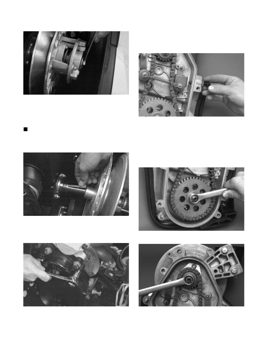
Fig. 8-115
SC013D
4. Slide the driven pulley off the driven shaft; then
remove the driven pulley from the engine
compartment. Account for the stub shaft, key, and
alignment washers.
NOTE: If the driven pulley is tight on the driven
shaft, pull the driven pulley off using the Driven
Pulley Puller (p/n 0744-023).
Fig. 8-116
AF120D
5. Remove the cap screws and lock washers securing
the chain-case cover; then remove the cover.
Fig. 8-117
AF111D
6. Loosen the mechanical chain tensioner bolt; then
remove the cotter pins and washers securing the
tensioner spring to the link pins. Remove the spring,
rollers, and washers.
Fig. 8-118
AF347D
7. Remove the flex nut securing the front roller cage
and roller. Remove the cage and roller.
8. Set the brake lever lock; then remove the lock nut
and spring washer securing the bottom sprocket and
the lock nut and spring washer securing the top
sprocket.
Fig. 8-119
AF345D
Fig. 8-120
AF344D
9. Slide both sprockets with chain off the shafts.
Account for washer(s) behind the top sprocket.
Release the brake lever lock.
8-34