Snowmobile Arctic Cat (2000 year). Manual - part 95
INSTALLING
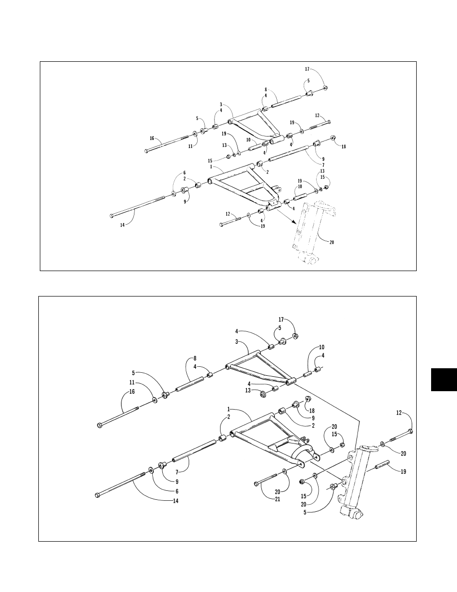
Fig. 7-69
733-341A
Fig. 7-70
0735-030
KEY
1. Lower Arm
2. Bearing
3. Upper Arm
4. Bearing
5. Serrated Axle
6. Washer
7. Tube
8. Tube
9. Axle
10. Axle
11. Washer
12. Cap Screw
13. Lock Washer
14. Cap Screw
15. Lock Nut
16. Cap Screw
17. Lock Nut
18. Nut
19. Washer
20. Spindle
KEY
1. Lower Arm
2. Bearing
3. Upper Arm
4. Bearing
5. Axle
6. Washer
7. Tube
8. Tube
9. Axle
10. Tube
11. Washer
12. Cap Screw
13. Insert
14. Cap Screw
15. Lock Nut
16. Cap Screw
17. Lock Nut
18. Lock Nut
19. Tube
20. Washer
21. Cap Screw
7
7-19