Snowmobile Arctic Cat (2000 year). Manual - part 91


  Index      Snowmobiles / ATV     Snowmobile Arctic Cat - service manual 2000 year


Search            


Content   ..  89  90  91  92   ..


Snowmobile Arctic Cat (2000 year). Manual - part 91


1. Carefully slide the steering post into position in the

chassis. Be careful not to hook any wires or hoses.

2. On the upper end of the steering post, apply a light

oil to the bearing halves and place into position
around the steering post; then place the bearing cap
between the steering support and the steering post.
Place the bearing housing into position and secure
with two cap screws, washers, and lock nuts.
Tighten to 2.5 kg-m (18 ft-lb).

Fig. 7-5

AL090

3. Secure the console with the machine screws. Make

sure all wiring connections are secure.

4. Place the adjuster block, handlebar assembly, and

adjuster caps into position; then secure with four
cap screws and lock nuts. Tighten lock nuts evenly
to 1.4 kg-m (10 ft-lb).

5. Install the handlebar pad.

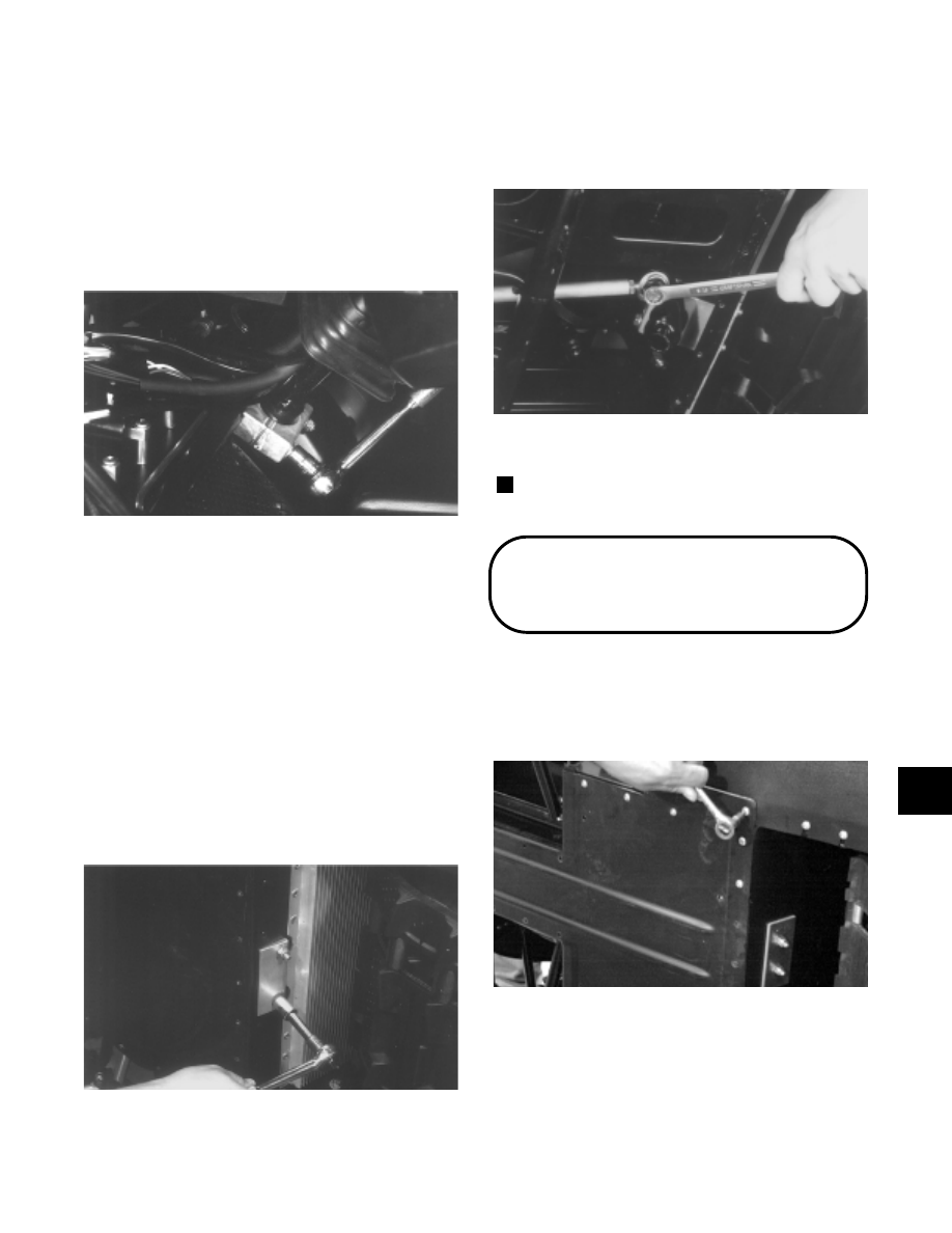
6. Tip the snowmobile on its side. On the lower end of

the steering post, apply a light oil to the bearing
halves and place into position around the steering
post; then place the bearing cap and bearing
housing into position. Install the backing plate and
secure with two cap screws, washers, and lock nuts.
Tighten to 2.5 kg-m (18 ft-lb).

Fig. 7-6

AL046

7. Place the tie rod into position. Secure with a cap

screw (coated with green Loctite #609) and lock
nut. Tighten to 4.2 kg-m (30 ft-lb). Install the cotter
pin and spread the pin.

Fig. 7-7

AL089

8. Install the skid plate. Secure with screws.

NOTE: Turn the handlebar to the full-left and

full-right to ensure free movement.

Steering Post

(AWS V)

REMOVING

1. Tip the snowmobile on its side. Remove the screws

securing the skid plate.

Fig. 7-8

AL144D

2. Remove the cotter pin, cap screw, and lock nut

securing the tie rod to the steering post.

7

7-3

Fig. 7-9

AL146D

3. Remove the two cap screws and lock nuts securing

the lower steering post bracket to the front end
assembly. Account for the backing plate, two
washers, bearing caps, bearing halves, and washers.

Fig. 7-10

AL145D

4. Tip the snowmobile upright. Remove the handlebar

pad.

Fig. 7-11

AL136D

5. Remove the four lock nuts and cap screws securing

the adjuster caps to the adjuster block; then remove
the caps. Place the handlebar assembly to the side.
Remove the adjuster block.

Fig. 7-12

AL147D

6. Remove the Phillips-head screws securing the

console to the gas tank.

Fig. 7-13

AL142D

7. Remove the two cap screws and lock nuts securing

the steering post to the steering support. Account
for the two washers, bearing caps, bearing halves,
washers, and backing plate.

Fig. 7-14

AL090

8. Remove the sheet metal screws securing the recoil

starter rope cup.

7-4

Fig. 7-15

AL149D

9. Remove the cap screws securing the recoil starter

rope wire form. Account for the lock nut.

Fig. 7-16

AL150D

10. Remove the cap screws securing the steering

support to the footrest (both sides).

Fig. 7-17

AL151D

11. Remove the cap screws securing the oil reservoir to

the steering support. Account for the lock nut and a
flat washer.

Fig. 7-18

AL152D

12. Remove the cap screws securing  the air-intake

silencer to the steering support. Account for the
washers, lock washers, and spacers.

Fig. 7-19

AL153D

13. Move the air-intake silencer forward.

Fig. 7-20

AL154D

14. Carefully slide the steering post out of the chassis.

Be careful not to hook any wires or hoses.

7

7-5

INSPECTING

NOTE: Whenever a part is worn excessively,

cracked, or damaged in any way, replacement is
necessary.

1. Inspect all welded areas for cracks or deterioration.

2. Inspect the steering post and steering-post brackets

for cracks, bends, or wear.

3. Inspect the bearing halves, bearing caps, and

bearing housings for cracks or wear.

INSTALLING

Fig. 7-21

0734-129

1. Carefully slide the steering post into position in the

chassis. Be careful not to hook any wires or hoses.

2. Secure the air-intake silencer to the steering support

with the washers, lock washers, spacers, and cap
screws.

Fig. 7-22

AL153D

3. Secure the oil reservoir to the steering support with

the washer and lock nut.

Fig. 7-23

AL152D

4. Secure the steering support to the footrest (both

sides) with the cap screws.

Fig. 7-24

AL151D

5. Secure the recoil starter rope wire form with the cap

screws and lock nut.

Fig. 7-25

AL150D

6. Secure the recoil starter rope cup with the sheet

metal screws.

KEY

1. Steering Post
2. Backing Plate
3. Ball Joint
4. Cap Screw
5. Lock Nut
6. Cap Screw
7. Bearing Housing
8. Bearing Half
9. Bearing Housing

10. Adjuster Cap
11. Adjuster Block
12. Bearing Housing
13. Cap Screw

14. Bearing Housing
15. Lock Nut
16. Backing Plate
17. Lock Nut
18. Ball Joint

19. Cotter Pin
20. Washer
21. Hex Nut
22. Tube
23. Hex Nut
24. Steering Stop
25. Washer

7-6


Content   ..  89  90  91  92   ..