Snowmobile Arctic Cat (2000 year). Manual - part 61


  Index      Snowmobiles / ATV     Snowmobile Arctic Cat - service manual 2000 year


Search            


Content   ..  59  60  61  62   ..


Snowmobile Arctic Cat (2000 year). Manual - part 61


PART

NUMBER

MODEL

SYSTEM

FUEL

COLOR/

SYMBOL

3005-463

1999 600

Batteryless

Both

l

3005-464

1999 600

Batteryless

Both

n

3005-465

1999 600

Batteryless

Both

s

3005-466

1999 500

Batteryless

Both

l

3005-467

1999 500

Batteryless

Both

n

3005-468

1999 500

Batteryless

Both

s

3005-469

1999 580

Batteryless

Both

l

3005-470

1999 580

Batteryless

Both

n

3005-471

1999 580

Batteryless

Both

s

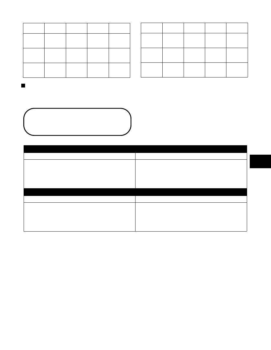
EFI EPROM CHIP USAGE CHART

(1999-2000)

PART

NUMBER

MODEL

SYSTEM

FUEL

COLOR/

SYMBOL

3005-672

2000 600

Batteryless

Both

l

3005-673

2000 600

Batteryless

Both

n

3005-674

2000 600

Batteryless

Both

s

3005-615

2000 500

Batteryless

Both

l

3005-616

2000 500

Batteryless

Both

n

3005-617

2000 500

Batteryless

Both

s

3005-618

2000 580

Batteryless

Both

l

3005-619

2000 580

Batteryless

Both

n

3005-620

2000 580

Batteryless

Both

s

NOTE: Kokusan EPROM must be marked K.

Problem: Too Rich

Condition

Remedy

1. LED trouble code

1. Replace problem sensor

2. Fuel pressure too high

2. Replace regulator

3. Fuel return hose obstructed

3. Service — replace hose — remove obstruction

4. Injectors leaking

4. Replace injectors

Problem: Too Lean

Condition

Remedy

1. LED trouble code

1. Replace problem sensor

2. Fuel pressure too low

2. Replace regulator/fuel pump

3. Vent hose obstructed

3. Remove obstruction

4. Fuel filter(s) obstructed

4. Replace fuel filter(s)

Troubleshooting

Fuel System (EFI)

4

4-63

686-425A

8500

EFI Wiring Diagram (500/580 cc)

4-64

0686-672

EFI Wiring Diagram (600 cc)

4

4-65

Fuel System

(Related Items)

Whenever any maintenance or inspection is made on the
fuel system in which fuel leakage may occur, there
should be no welding, smoking, or open flames in the
area.

NOTE: Some photographs used in this section

are used for clarity purposes only and are not
designed to depict actual conditions.

Fuel System

(Related Items)

Table of Contents

Oil-Injection Pump . . . . . . . . . . . . . . . 4-66
Synchronizing Oil-Injection Pump

. . . . . . . 4-67

Bleeding Oil-Injection System

. . . . . . . . . 4-67

Testing Oil-Injection Pump . . . . . . . . . . . 4-68
Testing Oil-Injection Check Valves . . . . . . . 4-68
Fuel Pump (Carbureted Models) . . . . . . . . 4-69
Air-Intake Silencer (One-Piece Style)

. . . . . 4-71

Air-Intake Silencer (Cover/Tool Tray Style)

. . 4-71

Gas Tank/Seat Assembly

. . . . . . . . . . . 4-72

Oil-Injection Pump

REMOVING

1. Turn the fuel shut-off valve to the CLOSED

position.

2. If applicable, remove the carburetors.

3. Disconnect the oil-supply hose from the pump and

plug to prevent oil drainage.

4. Remove the two oil-delivery hoses from the adapter

plates.

5. Disconnect the oil-injection cable.

6. Remove the two screws, lock washers, and washers

securing the oil-injection pump and retainer to the
crankcase.

Fig. 4-148

AB078

7. Pull the oil-injection pump away from the engine

and account for a gasket.

8. Turn the pump sideways; then remove the lower

union bolt. Account for two gaskets. Remove the
pump.

9. Remove the remaining union bolts securing the

check valves to the pump. Account for two gaskets.

10. Remove the check valves. Account for two gaskets.

INSTALLING

1. In turn on each front union bolt, install a gasket,

check valve, and gasket; then install on the
oil-injection pump.

2. Place the gasket and oil-injection pump near the

engine; then install the lower union bolt through a
gasket, check valve, and gasket.

3. Position the oil-injection pump on the engine

making sure the oil-injection pump gear is correctly
aligned with the oil-injection pump drive gear.

4. Secure the pump with two screws, lock washers,

and washers. Tighten screws to 0.7 kg-m (5 ft-lb).

5. Connect the two oil-delivery hoses to the adapter

plates. Secure with clamps.

6. Connect the oil-injection cable to the pump and

secure with the washer and E-clip.

7. Connect  the oil-supply  hose  to  the  oil-injection

pump inlet fitting. Secure with the clamp.

8. Bleed the oil-injection system (see Bleeding

Oil-Injection System in this sub-section).

9. Check the oil-injection system synchronization

(see Synchronizing Oil-Injection Pump in this
sub-section). Tighten the jam nuts securely.

10. If applicable, install the carburetors.

11. Turn the fuel shut-off valve to the OPEN position.

4-66


Content   ..  59  60  61  62   ..