Snowmobile Arctic Cat (2000 year). Manual - part 54
STARTING
1. To start an engine for the first time or after
performing service work on the fuel system, place
the emergency stop switch and the ignition switch
in the ON position. Disconnect the yellow water
temperature sensor lead wire at the ECU. Crank the
engine over 6-8 times with the recoil starter. With
the water tempeature sensor lead disconnected, the
fuel system will call for maximum mixture and the
system will charge faster. After 6-8 brisk pulls on
the recoil starter, reconnect the yellow sensor lead.
The engine should start in 2-3 additional pulls.
After charging the fuel system, the engine should
start in 3-4 pulls when cold.
2. Start the engine without compressing the throttle.
When the engine starts for the first time, do not
touch the throttle. It will idle slowly and may stop.
Repeat this procedure until the engine starts and
builds RPM on its own. This may require 3-4
restarts. Once the engine has been started and run,
the next cold start should occur in 2-3 pulls of the
recoil starter.
FLOODED ENGINE
If the engine should become flooded, set the brake lever
lock, compress the throttle lever to the full-open position,
and crank the engine over until it starts and clears itself.
Release the brake lever lock.
FUEL SYSTEM
The EFI fuel system consists of the following
components.
1. Gas tank
2. Electric high output fuel pump
3. Two pick-up valves with micron screens
4. High-pressure fuel hose
5. Fuel rail
6. Fuel pressure regulator
7. Throttle body assembly
8. Injectors
9. Fuel return hose
10. ECU
These above components are grouped into the fuel
handling system. They work together along with five
electrical sensors (listed below) and the ECU to provide
the engine with a precise fuel mixture for combustion.
The five sensors are the following.
1. Crankshaft Positioning Sensor
2. Intake Air Temperature Sensor
3. Water Temperature Sensor
4. Throttle Position Sensor
5. Barometric Pressure Sensor
The fuel is first drawn into the electric fuel pump
through two pick-up valves and hoses. The fuel is then
routed through a high-pressure fuel hose to the fuel rail.
The fuel pressure is maintained at 37.9 + 2.2 psi in the
fuel rail by the fuel regulator. If pressure exceeds this
amount, the regulator opens and returns excess fuel to
the gas tank through the fuel return hose.
With the fuel pressure maintained at a constant 37.9 +
2.2 psi, the ECU evaluates the information it receives
from the five electrical sensors and opens the injectors
for precise periods of time (pulse widths) to meet
engine demands.
NOTE: The entire EFI system depends on all coils
functioning properly on the stator.
Individual EFI
Components
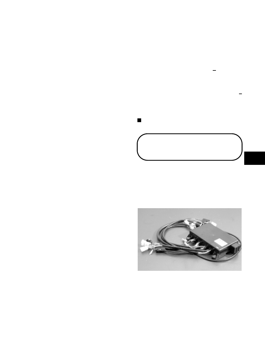
ECU
The ECU is the brain of the EFI system. It uses five
sensor inputs to determine the correct fuel/air ratio for
the engine given the existing conditions of altitude and
temperature.
Fig. 4-102
AO152D
If any of the sensors should fail while the engine is
running, the ECU will sense a problem and go into a
“limp home” mode. This is an over-rich condition and
will greatly reduce performance. However, the engine
will be protected from a possible lean condition and
engine damage.
4
4-35