Snowmobile Arctic Cat (2000 year). Manual - part 44


  Index      Snowmobiles / ATV     Snowmobile Arctic Cat - service manual 2000 year


Search            


Content   ..  42  43  44  45   ..


Snowmobile Arctic Cat (2000 year). Manual - part 44


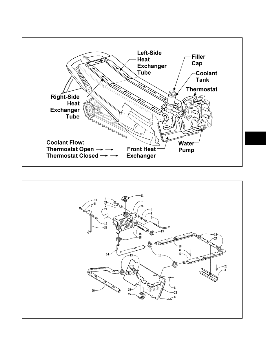
COOLING SYSTEM SCHEMATICS

Fig. 3-58

0734-451

Fig. 3-59

0734-956

KEY

1. Coolant Reservoir
2. Spacer
3. Guard
4. Vent Hose
5. Washer
6. Lock Washer
7. Cap Screw
8. Rivet
9. Lock Washer

10. Cap Screw
11. Cap
12. Lock Nut
13. Clamp
14. Hose
15. Hose
16. Heat Exchanger
17. Heat Exchanger
18. Clamp
19. Hose
20. Hose
21. Decal
22. Wire Form Bracket
23. Heat Exchanger
24. Washer
25. Cable Tie
26. Rivet
27. Hose

3

3-15

Fig. 3-60

0735-278

Fig. 3-61

0734-388

KEY

1. Coolant Reservoir
2. Hose
3. Clamp
4. Decal
5. Hose
6. Cable Tie
7. Lock Nut
8. Washer
9. Hose

10. Hose
11. Hose
12. Clamp
13. Cable Tie
14. Heat Exchanger
15. Machine Screw
16. Rivet
17. Cap

KEY

1. Coolant Reservoir
2. Hose
3. Clamp
4. Decal
5. Hose
6. Rivet
7. Lock Nut
8. Washer
9. Hose

10. Hose
11. Heat Exchanger
12. Clamp
13. Cable Tie
14. Hose Guard
15. Cap Screw
16. Rivet
17. Cap
18. Heat Exchanger
19. Hose
20. Hose
21. Cable Tie

3-16

Fig. 3-62

0734-334

Fig. 3-63

0734-305

KEY

1. Coolant Reservoir
2. Hose
3. Clamp
4. Decal
5. Hose
6. Rivet
7. Lock Nut
8. Washer
9. Hose

10. Hose
11. Heat Exchanger
12. Clamp
13. Cable Tie
14. Hose Guard
15. Machine Screw
16. Rivet
17. Cap
18. Heat Exchanger
19. Hose
20. Hose
21. Cable Tie

KEY

1. Coolant Reservoir
2. Hose
3. Clamp
4. Decal
5. Hose
6. Rivet
7. Lock Nut
8. Washer
9. Hose

10. Hose
11. Heat Exchanger
12. Clamp
13. Cable Tie
14. Guard
15. Machine Screw
16. Rivet
17. Cap
18. Heat Exchanger
19. Hose
20. Hose
21. Hose
22. Double T-Fitting
23. Hose
24. Clamp
25. Conduit
26. Cable Tie

3

3-17

Recoil Starter

REMOVING

1. Tie a slip-knot in the starter rope below the console

and allow the rope to slowly retract against the
starter case.

2. Remove the knot at the handle, remove the handle,

and account for the handle cap; then thread the rope
through the bushing in the console.

3. Remove the four  cap screws and  lock washers

securing the starter assembly to the magneto case;
then remove the starter assembly.

DISASSEMBLING

! WARNING

Always wear safety glasses when servicing the
recoil starter.

1. Secure the recoil starter in a vise.

! WARNING

During the disassembly procedure, continuous
downward pressure must be exerted on the reel
so it does not accidentally disengage and cause
injury.

2. Rotate the roller counterclockwise until the notch

of the roller is near the rope guide in the case. Guide
the rope into the notch and slowly allow the roller
to retract until all recoil spring tension is released.

Fig. 3-64

B522

! WARNING

Care must be taken when allowing the recoil
roller to unwind. Make sure all spring tension is
released before continuing.

3. While exerting downward pressure on the drive

plate, remove the nut and washer.

Fig. 3-65

B523

4. Slowly release the drive plate and lift the drive plate

with friction spring free of the recoil roller.

5. Remove the friction spring from the drive plate.

Fig. 3-66

B524

6. Remove the pawl; then remove the return spring.

Fig. 3-67

B525

7. Carefully lift the roller free of the case making sure

the main spring does not accidentally disengage
from the case.

3-18


Content   ..  42  43  44  45   ..