Snowmobile Arctic Cat (2000 year). Manual - part 42
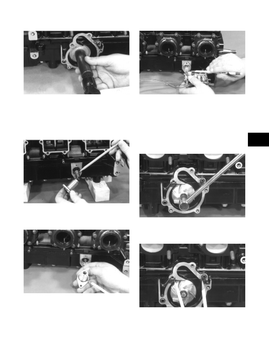
Fig. 3-22
AN261
6. Apply a light coat of grease to the sealing surface of
the oil-injection pump driveshaft; then install Oil
Seal Installation Tool (p/n 0644-219) at the end of
the shaft. Twist the shaft as it is pushed through the
oil and water pump seals; then remove the tool.
Position the shim on the oil pump end of the shaft.
Fig. 3-23
AN231
7. Install the oil-injection pump retainer O-ring and
retainer.
Fig. 3-24
AN184
8. Install the O-ring and the oil-injection pump. Make
sure the pump shaft and oil pump align. Secure with
two screws and washers. Tighten the two screws to
0.7 kg-m (5 ft-lb).
Fig. 3-25
AN183
9. Place the lower check valve into position; then
secure with the gaskets and union cap screw.
Tighten securely.
10. Place the impeller into position and secure with a
cap screw and washer. Be sure the rubber side of the
washer is directed towards the impeller. Apply blue
Loctite #242 to the threads of the cap screw and
tighten to 0.8-1.2 kg-m (6-9 ft-lb).
Fig. 3-26
AN178
11. Apply sealant to the crankcase seam; then install
the alignment pins into the crankcase (if removed).
Fig. 3-27
AN179
12. Position the O-ring into the water pump cover; then
install the cover. Secure with the screws. Tighten to
1.1 kg-m (8 ft-lb).
3
3-7