Snowmobile Arctic Cat (2000 year). Manual - part 21
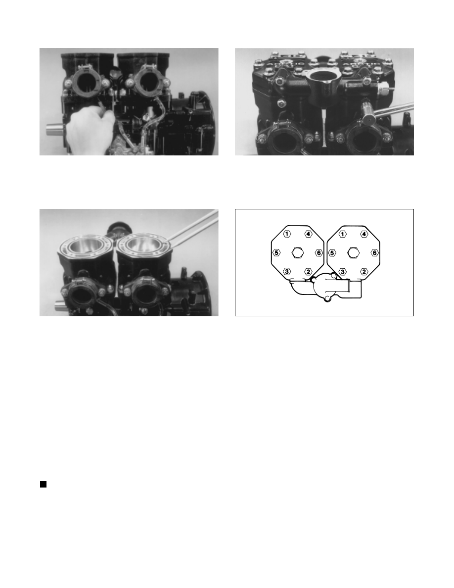
Fig. 2-287
AN111
34. Install the two cylinder O-rings on the top of each
cylinder making sure they are correctly positioned
in the grooves.
Fig. 2-288
AN110
35. Place new O-rings onto each of the twelve head cap
screws. Place four of these cap screws into one of
the cylinder heads. Thread the spark plug in part
way; then while holding the head above the cylinder,
carefully start all four cap screws while observing
the cylinder O-rings to make sure they remain in
position. Slowly place the head into position on top
of the O-rings. Start the remaining two cap screws
being very careful not to move the cylinder head.
Repeat the same procedure on the remaining head.
ONLY FINGER-TIGHTEN AT THIS TIME.
36. Apply a thin coat of sealant to the two thermostat
housing gaskets. Place the gaskets and housing into
position and secure with four cap screws and
washers. Tighten the four cap screws in a crisscross
pattern to 0.7-1 kg-m (5-7 ft-lb).
NOTE: The thermostat housing cap screws must
be tightened before tightening the cap screws
securing the head. This will allow the gasket
surfaces of the head to align with the housing and
prevent any coolant leakage.
Fig. 2-289
AN113
37. Tighten the cap screws securing the head in three
steps to 1.8-2.8 kg-m (13-20 ft-lb) using the pattern
shown. Pressure test the engine (see Section 3).
Fig. 2-290
0728-138
38. Place the thermostat, gasket, and cap into position.
Secure the cap with three cap screws tightened to
0.7-1 kg-m (5-7 ft-lb).
39. On the 550 cc, place the PTO-end plate into position
on the crankcase; then apply blue Loctite #242 to the
screws and tighten securely.
40. Place the stator plate into position over the
crankshaft end.
41. Install the lock washers and washers on the
Allen-head cap screws; then apply blue Loctite #242
to the threads of the stator plate Allen-head cap
screws and install. DO NOT TIGHTEN AT THIS
TIME.
42. Align the stator plate with the alignment mark made
during disassembly. Tighten both stator plate screws
securely.
2-68