Snowmobile Polaris DEEP SNOW (2005 year). Manual - part 25
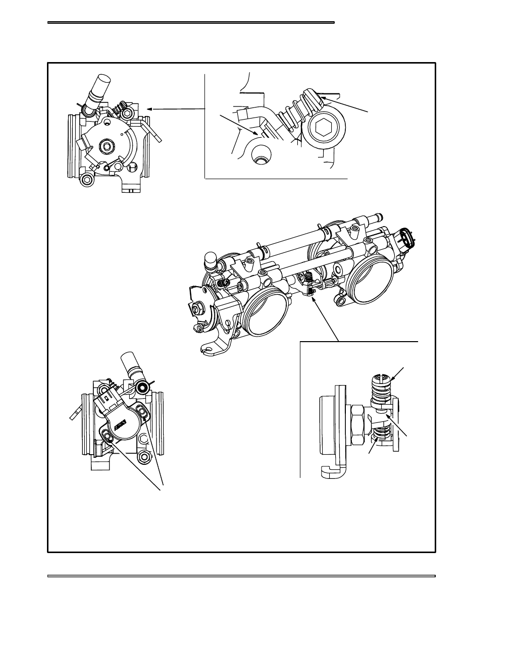
FUEL DELIVERY
4.25
THROTTLE BODY
A
B
C
D
E
F
LOCK NUT AND
ADJUSTER STYLE
NOT SHOWN
Index Snowmobiles / ATV Snowmobile Polaris DEEP SNOW (TRAIL RMK, 600 RMK, 700 RMK, 800 RMK, 900 RMK, 600 SWITCHBACK, 800 SWITCHBACK) - service manual 2005 year
|
|
|
FUEL DELIVERY 4.25 THROTTLE BODY A B C D E F LOCK NUT AND ADJUSTER STYLE NOT SHOWN |