Snowmobile Polaris DEEP SNOW (2005 year). Manual - part 10
GENERAL INFORMATION
2.19
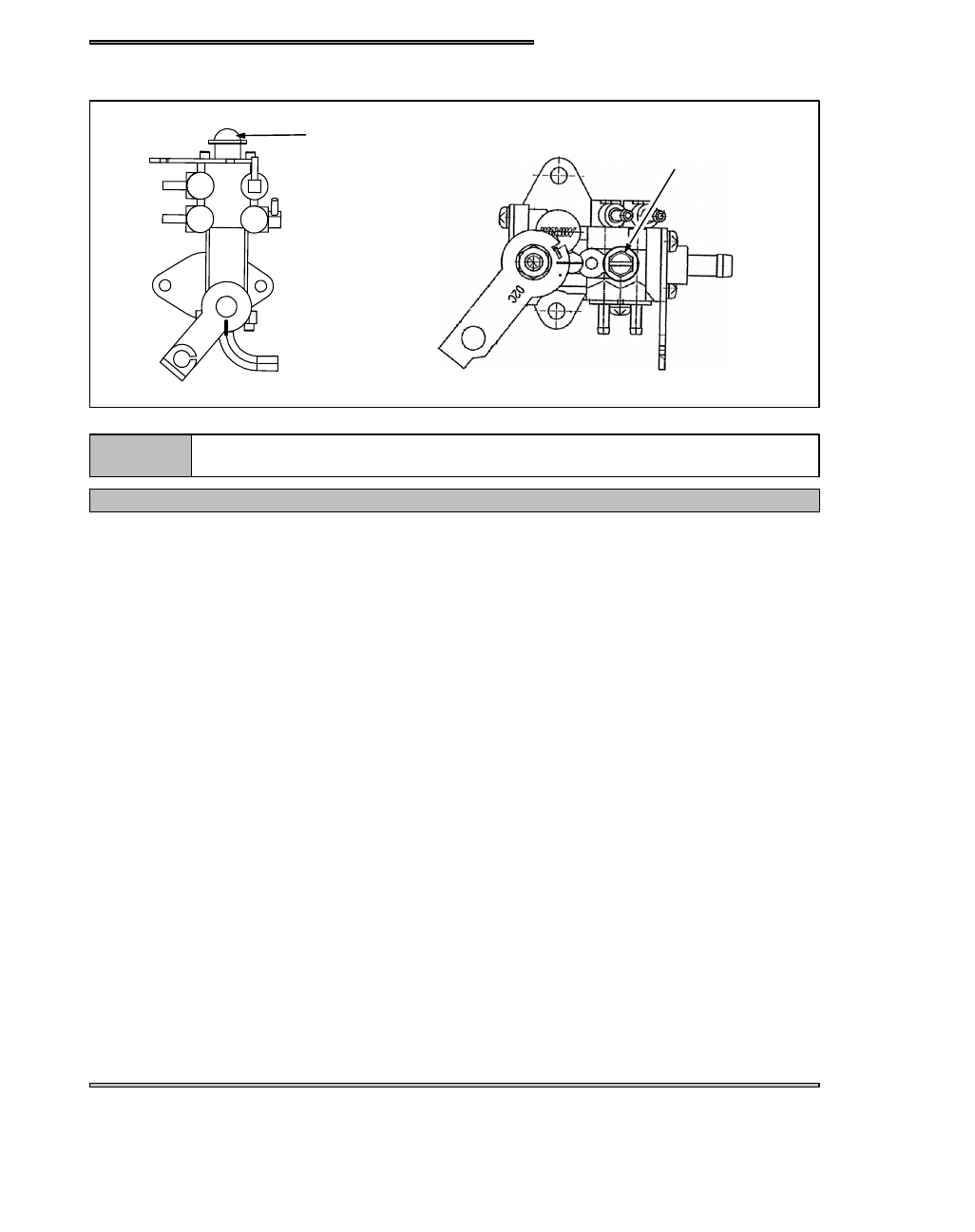
OIL PUMP BLEEDING
(A)
(A)
FUSION OIL PUMP
NOTE:
Any time the engine is disassembled or repaired, it is important that the oil supply from the pump
to the engine be checked.
IMPORTANT: The oil pump must always be bled following any service to the injector system or engine.
Fill oil reservoir with the appropriate Polaris injector oil. This will add pressure to the oil lines to aid in bleeding the air out.
Loosen bleed screw (A). After :30 seconds or so, oil should flow from beneath the screw head to indicate the pump is free of air.
Tighten bleed bleed screw securely.