Snowmobile Polaris DEEP SNOW (2005 year). Manual - part 8


  Index      Snowmobiles / ATV     Snowmobile Polaris DEEP SNOW (TRAIL RMK, 600 RMK, 700 RMK, 800 RMK, 900 RMK, 600 SWITCHBACK, 800 SWITCHBACK) - service manual 2005 year


Search            


Content   ..  6  7  8  9   ..


Snowmobile Polaris DEEP SNOW (2005 year). Manual - part 8


GENERAL INFORMATION

2.11

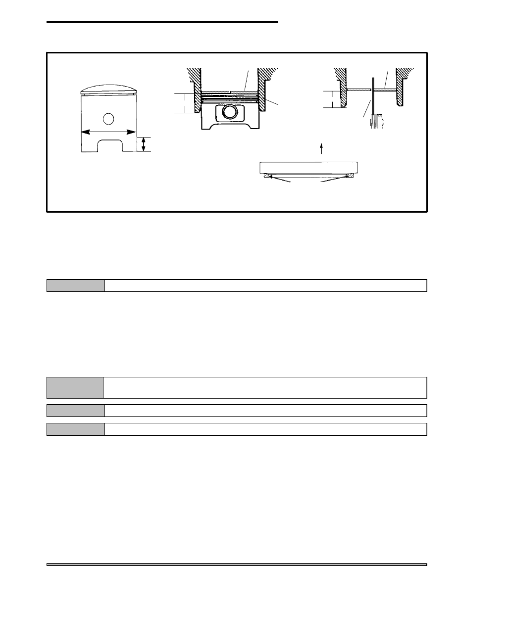
PISTON INSPECTION / MEASUREMENT

90° to pin

DOMESTIC ENGINES - Measure 3/8″ (10.0mm)

up from bottom of skirt

Piston Ring

Feeler Gauge

1/2″ (1.3cm.)

Straight Edge

Keystone Piston Ring Cutaway

Up

FUJI ENGINES - Measure 1/2″ (12.7mm) up

from bottom of skirt

1/2″ (1.3cm.)

Cylinder

Piston Ring

A

B

C

D

Check piston for scoring or cracks in piston crown or pin area. Excessive carbon buildup below the ring lands is an indication

of piston, ring or cylinder wear.

For Libertyt engines, measure piston outside diameter at a point 3/8” (10mm) up from the bottom of the skirt at a 90_ angle

to the direction of the piston pin (diagram A).

For Fuji engines, measure piston outside diameter at a point that is 1/2” (12.7mm) up form the bottom of the skirt at a 90_ angle

to the direction of the piston pin (diagram A).

NOTE:

The piston must be measured at this point to provide accurate piston to cylinder measurements.

Subtract this measurement from the minimum cylinder measurement recorded previously when you recorded the cylinder mea-

surements. If clearance exceeds the service limit, the cylinder should be re-bored and new pistons and rings installed. Refer to

piston to cylinder clearance limits in the General Information section listed per model.

PISTON RING INSTALLED GAP

Position the ring 1/2“ (1.3 cm) from the top of the cylinder using the piston to push it squarely into place. Measure installed gap

with a feeler gauge at both the top and bottom of the cylinder (diagram B).

NOTE:

A difference in end gap indicates cylinder taper. The cylinder should be measured for excessive
taper and out of round. Replace rings if the installed end gap exceeds the service limit.

NOTE:

Always check piston ring installed gap after re-boring a cylinder or when installing new rings.

NOTE:

Piston rings are installed with marking or beveled side up see diagram D.

GENERAL INFORMATION

2.12

CYLINDER HONING

The cylinder bore must be de-glazed whenever new piston rings are installed. A light honing with fine stones removes only a

very small amount of material. A proper crosshatch pattern is important to provide a surface that will hold oil, and allow the rings

to seat properly. If the crosshatch is too steep, oil retention will be reduced. A crosshatch angle which is too shallow will cause

ring vibration, poor sealing, and overheating of the rings due to blow-by and reduced contact with the cylinder wall. Service life

of the pistons and rings will be greatly reduced.

CYLINDER HONE SELECTION

A Nikasil cylinder can be lightly honed with
a soft stone hone but can not be oversized.

NOTE:

DE--GLAZING

If cylinder wear or damage is minimal, honing the cylinder lightly with

finish stones. Follow the procedure outlined above

HONING TO OVERSIZE (340 AND 500 FUJI ENGINES ONLY)

If cylinder wear or damage is excessive, it will be necessary to oversize the cylinder using a new oversize piston and rings. This

may be accomplished by either boring the cylinder and then finish honing to the final bore size, or by rough honing followed by

finish honing.

Portable rigid hones are not recommended for oversizing cylinders, cylinder boring, and finish honing.

The use of an arbor type honing machine is recommended.

NOTE:

For oversize honing always wet hone using honing oil and a coarse roughing stone. Measure the new piston at room temperature

(see piston measurement) and rough hone to the size of the piston or slightly larger. Always leave .002” - .003“ (.05 - .07 mm)

for finish honing. Complete the sizing with fine grit stones to provide the proper cross-hatch finish and required piston clearance.

Inspect cylinder for taper and out-of-round. Taper or out-of-round on the finished bore should not exceed .0004“ (.002mm).

NOTE:

Always check piston to cylinder clearance and piston ring installed gap after boring/honing is complete.

HONING PROCEDURE

Wash the cylinder with solvent.

Clamp the cylinder in a soft jawed vise by the exhaust port studs.

Place hone in cylinder and tighten stone adjusting knob until stone contacts the cylinder walls (DO NOT OVERTIGHTEN).

Cylinders may be wet or dry honed depending on the hone manufacturer’s recommendations. Wet honing removes more material

faster and leaves a more distinct pattern in the bore. Using a 1/2“ (13 mm) drill motor rotating at a speed of 300-500 RPM, run

the hone in and out of the cylinder rapidly until cutting tension decreases. Remember to keep the hone drive shaft centered to

prevent edge loading and always bring the stone approximately 1/2“ (1.3 cm) beyond the bore at the end of each stroke.

Release the hone at regular intervals to inspect bore size and finish.

EXAMPLE OF A CROSS HATCH PATTERN

GENERAL INFORMATION

2.13

PORT CHAMFERING

Remove the sharp edges at the bottom and top of each port whenever boring or honing is performed. Make sure there are no sharp

edges.

IMPORTANT:

It is very important that the cylinder be thoroughly cleaned after honing to remove all grit material.

Wash the cylinder in a solvent, then in hot soapy water. Pay close attention to areas where the cylinder

sleeve meets the aluminum casting (transfer port area). Use electrical contact cleaner if necessary to

clean these areas. Rinse thoroughly, dry with compressed air, and oil the bore immediately with Polaris

Premium 2 Cycle Lubricant.

CLEANING THE CYLINDER AFTER HONING

It is very important that the cylinder be thoroughly cleaned after honing to remove all grit material. Wash the cylinder in a solvent,

then in hot soapy water. Pay close attention to areas where the cylinder sleeve meets the aluminum casting (transfer port area).

Use electrical contact cleaner if necessary to clean these areas. Rinse thoroughly, dry with compressed air, and oil the bore im-

mediately with Polaris Premium 2 Cycle Lubricant.

Always check piston to cylinder clearance and piston ring installed gap after boring/honing is
complete!

NOTE:

CRANKCASE INSPECTION / BEARING FIT

Any time crankshaft bearing failure occurs and the case is to be reused,

Polaris recommends checking the bearing fit into the case halves using

the following procedure.

With case halves cleaned, press a replacement bearing into each of the

main bearing journals to determine a basic amount of press fit.

NOTE:

Crankcase Bearing Interference Fit:.001” -- .002” (.026 -- .051mm)

Do a comparison check of all journals by manually forcing the bearing into the bearing seats noting if
any are noticeably loose or tight. Normal hand installation will be an indication of the recommended
interference fit. If the bearing falls out of the case when the case is inverted, or if the crankcase bear-
ing surface is severely galled or damaged, the case should be replaced

NOTE:

CRANKSHAFT MAIN BEARING INSPECTION

Clean crankshaft thoroughly and oil main and connecting rod bearings with Polaris engine oil. Carefully check each main bearing

on the shaft.

Due to extremely close tolerances, the bearings must be inspected visually, and by feel. Look for signs

of discoloration, scoring or galling. Turn the outer race of each bearing. The bearings should turn

smoothly and quietly. The inner race of each bearing should fit tightly on the crankshaft. The outer

race should be firm with minimal side to side movement and no detectable up and down movement.

Replace any loose or rough bearings.

NOTE:

GENERAL INFORMATION

2.14

CONNECTING ROD (BIG END) BEARING INSPECTION

Measure connecting rod big end side clearance with a feeler gauge. 500/600 Libertyt Engines should have a clearance of

(.28 --.75mm) and 700/800/900 Libertyt Engines should have (.28 -- .70mm) and be equal on all rods (within .002″) Rotate rod

on crankshaft and check for rough spots. Check radial end play in rod by supporting rod against one thrust washer and alternately

applying up and down pressure. Replace bearing, pin, and thrust washers if side clearance is excessive or if there is any up and

down movement detectable in the big end bearing.

Specialized equipment and a sound knowledge
of crankshaft repair and straightening is required
to perform crankshaft work safely and correctly.
Crankshaft repair should be performed by
trained Polaris service technicians in a properly
equipped shop.

NOTE:

PISTON PIN / NEEDLE BEARING INSPECTION

Clean needle bearing in solvent and dry with compressed air.

Inspect needle cage carefully for cracks or shiny spots which indicate

wear. Replace needle bearings if worn or cracked, and always replace

them if piston damage has occurred.

Visually inspect piston pin for damage, discoloration, or wear. Run your

fingernail along the length of the pin and replace it if any rough spots,

galling or wear is detected.

CONNECTING ROD SMALL END INSPECTION

Clean small end of connecting rod and inspect inner bore with a magni-

fying glass. Look for any surface irregularities including pitting, wear,

or dents.

Run your fingernail around the inside of the rod and check for rough

spots, galling, or wear.

Oil and install needle bearing and pin in connecting rod. Rotate pin

slowly and check for rough spots or any resistance to movement. Slide

pin back and forth through bearing while rotating and check for rough

spots.

With pin and bearing centered in rod, twist ends back and forth in all

directions to check for excessive axial play. Pull up and down evenly

on both ends of pin to check for radial play. Replace pin and bearing

if there is any resistance to rotation or excessive axial or radial move-

ment. If play or roughness is evident with a new pin and bearing, replace

the connecting rod.

Within .002” (.05mm)


Content   ..  6  7  8  9   ..