COMBINE HARVESTER AW70V, VNQ, AW82V, VNQ. Manual - part 22
Periodic Inspection
89
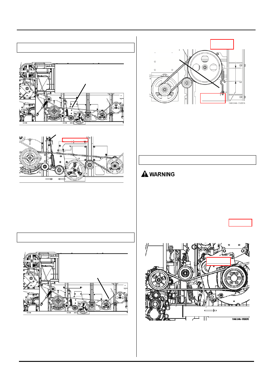
Screening belt
<Adjusting>
1. Remove the lower cover of the threshing section.
2. Loosen the lock nut and turn the adjusting nut to
change the spring length.
3. Fix it with the lock nut.
Swing separator drive belt
Adjust the tension spring length to 106±2mm.
<Adjusting>
1. Remove the lower cover of the threshing section.
2. Loosen the lock nut and turn the adjusting nut to
change the spring length.
3. Fix it with the lock nut.
Transmission drive belt
Be sure to fix the safety lock of the header.
Otherwise, it may fall down rapidly and
cause injuries.
<Adjusting>
1. Loosen the lock nut, and use the nut to adjust the
hook length of traveling tension spring to 150±2mm.
2. Fix it with the lock nut.
Screening belt
Adjusting part
198
±
2mm
106
±
2mm
Adjusting part
Swing separator drive belt
150
±
2mm