COMBINE HARVESTER AW70V, VNQ, AW82V, VNQ. Manual - part 23


  Index      Combines     YANMAR COMBINE HARVESTER AW70V, VNQ, AW82V, VNQ - manual


Search            


Content   ..  21  22  23  24   ..


COMBINE HARVESTER AW70V, VNQ, AW82V, VNQ. Manual - part 23


Periodic Inspection


93 


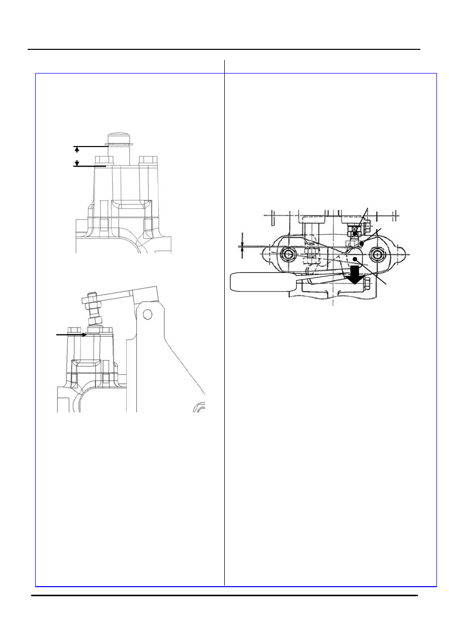
The spool retaining ring clearance on the upper side of 
the actuator when the turning lever is fully turned down 
G: 0-1 mm (both right and left side) 
 

<The turning lever is in the neutral position> 


<The turning lever is fully turned down> 


If dimension G is more than the specified dimension, 
the following problem may occur.   
- Turning with one of the side clutch brakes engaged 

cannot be performed at an early stage. 

 
[Note] 
Be sure to lock with the nut. 


4. Clearance adjustment between the SC lever and 

the machine bolt attached at the bottom of the 
actuator. 

 
The clearance between the machine bolt and the SC 
lever while taking the play in the SC lever at the bottom. 
J: 0-0.5 mm (both right and left) 
 
[Note] 

  Make sure that dimension J is not a minus value. 

(SC lever is being pushed.) 

  Be sure to lock with the nut. 


If dimension J is more than the specified dimension, the 
following problem may occur.- Turning with one of the 
side clutch brakes engaged cannot be performed at an 
early stage. 
 
If dimension J is a minus value, the following problem 
may occur. 
- Parts inside the transmission become worn 
- Transmission oil temperature increases 
 
5. Checks after adjustment 
 

  Machine turns with one of the side clutch brakes 

engaged (inner crawler stops) when the turning 
lever is fully pushed down. (Both right and left) 

  Turning with one of the side clutches disengaged, 

gradual turning, or turning with one of the side 
clutch brakes engaged, can be performed 
depending on the pushing angle of the turning 
lever. (Both right and left) 

  The response that the operator receives from the 

right and left sides is the same. 

  Nut is not loose and adjustment is not displaced 

after the test operation. 


Lock nut

Machine bolt

SC lever

SC lever play 
direction

Periodic Inspection


94 


22. Checking and adjusting the 
crawler


Jack up the chassis and the lower part of transmission 
to adjust the gap between the 4th track roller and the 
crawler to 12.5±2.5mm. 
 
<Adjusting> 
Jack up the machine on a level ground. The jack 
capacity must be over 3 tons. Support the chassis 
(pipe) , left and right sides of chassis. 


Add a buffer (wood plank) between the jack and 
transmission 


<Adjusting> 
1- Remove the adjust nut stopper. 
2- Loosen the lock nuts. 
3- Turn the adjusting nut to set the gap. 


[Precaution] 

Do not tension the crawler too tight (gap below 12.5±
2.5mm)


The crawler will be lengthened within a short time if it is 
excessively tensioned. As a result, the gap between the 
driving sprocket and the crawler will be widened, and 
the crawler iron core may be in contact with the driving 
sprocket, causing abnormal wear and damage. 


Left side of chassis 

Right side of chassis 

Gap

Tension 

bolt 

Adjusting

nut 

Periodic Inspection


95 


<Crawler structure>


<Common damages and failures of the crawler and the causes> 

-Most related         -Related


              Cause 


Damage/failure 

Tension of 

crawler 

Driving 

method 

Road 

condition 

Poor 

cleaning/ 

maintenance 

Poor storage

Iron core wear, breakage and 

fall-off 


Rib/projecting part damage 


Damage of crawler inner side 


Fatigue/damage of each parts 


Wire cord breakage 


Driving sprocket wear 


Track roller / idler roller wear 


Insufficient traction 


Crawler falling off wheel 


Driving  

sprocket hole 

Retaining wheel 
projection 

Rubber

Inner side of crawler 

Grounding side 

 of crawler 

Wire code

Iron code

Rib (protection)

Periodic Inspection


96 


<Main causes of crawler damage>


Traveling/moving along steps or ridges 


Traveling over bridge. 


Traveling on roads with sharp bumps (steel bar, 
stone etc.).


[Other precautions] 


Operating temperature -20~55. 


Chemicals, oil and salt in sea water may damage the track. 


It is prohibited to climb up steps or cross deep ditches directly. Any steps or deep ditches should be leveled with 
soil or wood.


It is prohibited to drive obliquely on a slope to prevent accidents caused by the crawler running off the rails. 


It is prohibited to turn abruptly during traveling at a high speed. Otherwise, the crawler may fall off the rails and 
cause accident.


It is prohibited to travel on roads in a long distance. Use a truck or other vehicles for long-distance traveling. 


It is prohibited to use any ramp boards without anti-skid measures. 


Check the crawler tension on a regular basis for timely adjustment. Otherwise, wear of the driving sprocket and 
iron core of the track may be early.


Check the wear condition of driving sprocket, idler wheel and track roller, and replace when necessary to 
prevent damage and crack of the crawler.


Try to avoid crossing the ridge or ditch during field operation, so as to prevent damage and crack of the crawler. 


Timely remove the mud, straw and other foreign matters stuck in the crawler if any. Otherwise, the traveling 
resistance may be increased.


Reducing the power may lead to crawler crack, inner side scratch and early wear of the driving sprocket. 


The track must be correctly tensioned. It may run off the rails if it is tensioned too loosely, or break if tensioned 
too tight. In case of abnormal wear of the driving sprocket, the crawler core may be drawn out and lead to 
crawler damage, as shown below.


[Note] 
The driving sprocket should be replaced if the dimension measured by the calipers shown above is <20mm. 


Wear condition of driving sprocket


Content   ..  21  22  23  24   ..