Challenger Terra Gator 3244 Chassis. Manual - part 18
 

  Index      Challenger     Challenger Terra Gator 3244 Chassis - service repair manual 2009 year


Search            


Content   ..  16  17  18  19   ..


Challenger Terra Gator 3244 Chassis. Manual - part 18


627333-A  

1-71

Tooling list

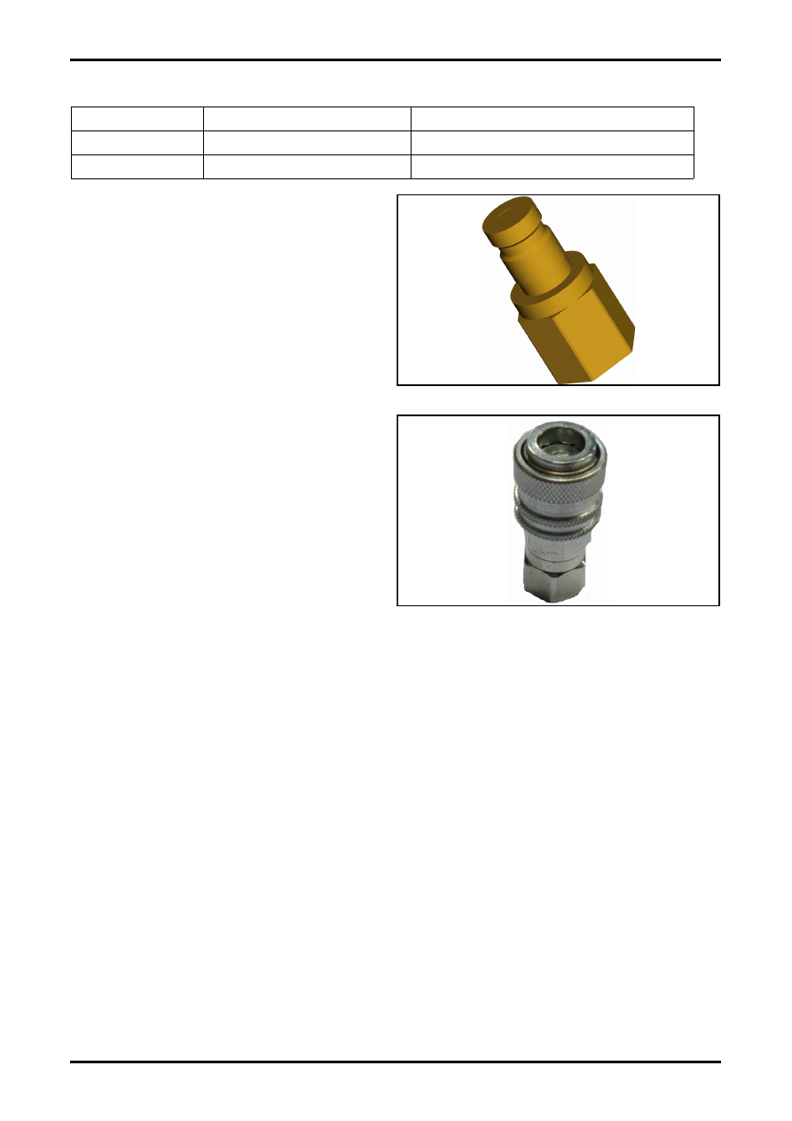
Quick Connect Couplers

FIG. 6: Testpoint 7/16 UNF DF (male).

FIG. 7: Testpoint 1/4 NPT DF (female).

Partnumber

Description

Information

681359

Testpoint 7/16 UNF DF (male)

7/16 UNF, Female threaded

833317

Testpoint 1/4 UNF DF (female)

1/4 UNF, Female threaded

FIG. 6

q000174s

FIG. 7

q000169s

627333-A  

2-i

Contents

Challenger

®

Terra Gator 3244

Chassis

SERVICE MANUAL

627333-A

02 - Engine

Contents

INTRODUCTION

Introduction ................................................................................................................................................ 2-1

Specifications and Standards Concerning Fuel, Oil and Coolant  .............................................................. 2-1

Fuel Quality  ......................................................................................................................................... 2-1

Oil Quality ............................................................................................................................................ 2-1

Coolant Quality .................................................................................................................................... 2-1

CAT C11 Diesel  ......................................................................................................................................... 2-1

Specification ........................................................................................................................................ 2-1

Engine Oil Type ................................................................................................................................... 2-1

Lifting And Storage  .................................................................................................................................... 2-2

Lifting ................................................................................................................................................... 2-2

Storage ................................................................................................................................................ 2-2

Engine Service Manual .............................................................................................................................. 2-2

ENGINE COMPONENTS

Engine Component Locations .................................................................................................................... 2-3

Left Side  .............................................................................................................................................. 2-3

Right Side ............................................................................................................................................ 2-4

Sensor .......................................................................................................................................................  2-5

Sensor Overview  ................................................................................................................................. 2-5

Replacement Senors ...........................................................................................................................  2-6

Sensor Location  .................................................................................................................................. 2-7

Cooling ..................................................................................................................................................... 2-10

ENGINE MAINTENANCE

Engine Valve Lash Inspect / Adjust  ......................................................................................................... 2-11

Valve Lash Check  ............................................................................................................................. 2-12

Valve Lash Adjustment ...................................................................................................................... 2-12

Engine Removal and Installation  ............................................................................................................. 2-14

INDEX ......................................................................................................................................................... 2-15

627333-A  

2-1

Introduction

INTRODUCTION

INTRODUCTION

The machine utilizes a diesel engine manufactured by

CAT for AGCO. 

Many of the components are mounted and operate

directly with the CAT engine. This section describes

troubleshooting, error codes and the proper procedures

to remove and install components.

If an internal engine problem arises that warrents

engine, please contact your AGCO-dealer or the engine

service center.

SPECIFICATIONS AND STANDARDS 
CONCERNING FUEL, OIL AND COOLANT

The engines fitted on the machine series comply with

standards concerning emissions imposed by the

authorities. (EU97/68/EC and 2007 US EPA and

California Regulations for Large Non Road

Compression Ignition Engines)

The quality of the fluids used in these engines, as well as

the servicing schedule, must be respected in order to

keep pollution emission levels low and to maintain the

machine’s performance throughout its life.

Fuel Quality

The fuel must comply with standard DIN EN 590 and

with the following specifications:

Density at 15 °C (59 °F): 0,82 to 0,84 kg/dm

Viscosity at 40 °C (104 °F): 2 to 4,5 mm/sec

Cetane index: min 51

Sulphur content: max 0,005p-%

Water content: max 200mg/kg

Oil Quality

The oil used must comply with API CI-4 standard.

Coolant Quality

The coolant used must comply with the ASTM d 3306

standard. It must consist of pure water and

ethylene/propylene glycol type antifreeze in the following

proportions:

40-60% water

40-60% antifreeze

The ideal ratio is 50% water to 50% antifreeze.

CAT C11 DIESEL

Specification

Specification CAT C11 Diesel with Turbo Intercooler.

6 Cylinder, 11.1 liter engine with direct  injection;

Injection order: 1-5-3-6-2-4;

Max injection pressure  of 2070 bar (30 000 PSI);

Oil pressure 3,8 bar (54 PSI);

Oil capacity of 40 L (10,6 gallon);

Oil type, SAE 15W40 API Class CF-4

Valve clearance of;

Inlet 0,38 mm (± 0,08 mm)

Exhaust 0.64 mm (± 0,08 mm)

Engine Oil Type

Generally, use the highest oil viscosity that is available to

met the requirement for the temperature at start-up.

If ambient temperature conditions at engine start-up

require the use of multigrade SAE 0W oil, SAE 0W-40

viscosity grade is generally preferred over SAE 0W-20

or SAE 0W-30.

NOTE: SAE 10W-30 is the preferred viscosity grade for

the engine when the ambient temperature is

above -18°C (0°F) and below 40°C (104°F).

NOTE: Supplemental heat is recommended for

cold-soaked starts below the minimum ambient

temperature. Supplemental heat may be

required for cold-soaked starts that are above

the minimum temperature that is stated,

depending on the parasitic load and other

factors. Cold-soaked starts occur when the

engine has not been operated for a period of

time and when the cooler ambient temperatures

allow the oil to become more viscous.

Lubricant Viscosities for Ambient Temperatures

Ambient Temperature

Viscosity Grade

Minimum

Maximum

SAE 0W-20

-40°C (-40°F)

10°C (50°F)

SAE 0W-30

-40°C (-40°F)

30°C (86°F)

SAE 0W-40

-40°C (-40°F)

40°C (104°F)

SAE 5W-30

-30°C (-22°F)

30°C (86°F)

SAE 5W-40

-30°C (-22°F)

50°C (122°F)

SAE 10W-30

-18°C (-0°F)

40°C (104°F)

SAE 10W-40

-18°C (-0°F)

50°C (122°F)

SAE 15W-40

-9.5°C (-15°F)

50°C (122°F)

Introduction

2-2

627333-A  

LIFTING AND STORAGE

Lifting

FIG. 1: Never band the eyebolts and the brackets.

Only load the eyebolts and the brackets under tension.

Remember that the capacity of an eyebolt is less as the

angle between the supporting members and the object

becomes less than 90 °.

When it is necessary to remove a compnent at an

angle, only use a link bracket that is properly rated for

the weight.

Use a hoist to remove heavy components. Use an

adjustable lifting beam to lift the engine. All supporting

members (chains and cables) should be parallel to

each other. The chains and cables should be

perpendicular to the top of the object that is being lifted.

Some removals require lifting the fixtures in order to

obtain proper balance and safety.

To remove the engine ONLY, use the lifting eyes that

are on the engine.

Lifting eyes are designed and installed for the specific

engine arrangement. Alterations to the lifting eyes

and/or the engine make the lifting eyes and the lifting

fixtures obsolete. If alterations are made, ensure that

proper lifting devices are provided. Consult your engine

service center for information regarding fixtures for

proper engine lifting.

The weight of the engine is approximately 1250 Kg

(2760 lb).

Storage

If the engine will not be started for several weeks, the

lubricating oil will drain from the cylinder walls and from

the piston rings. Rust can form on the cylinder liner

surface. Rust on the cylinder liner surface will cause

increased engine wear and a reduction in engine

service life.

To help prevent which excessive engine wear, use the

following guidelines how are described in the engine

manual.

ENGINE SERVICE MANUAL

CAT only granted service manual of the engine which

match with the serial number of the engine.

FIG. 1

Q000019S


Content   ..  16  17  18  19   ..