Huawei OptiX OSN 3500. Technical Manual - part 3

Board
Slots
Slots
Interface
available(80G
available(40G
type
Cooperating
Board
Full name
cross-connect
cross-connect
board
capacity)
capacity)
OU08
8 × STM-1 optical
SLOT19/21/23/25/
Not support.
SC, LC
SEP1
interface board
29/31/33/35
EU04
4 × STM-1 electrical
SLOT19/21/23/25/
SLOT19/21/23/25/
SMB
SEP1
interface board
29/31/33/35
29/31/33/35
TSB8
8 × PDH interface
SLOT19/20/35/36
SLOT19/20/35/36
None
EU08 and SEP1,
switching & bridging
or D34S and PD3
board
TSB4
4 × PDH interface
SLOT19/35
SLOT19/35
None
MU04 and SPQ4,
switching & bridging
EU04 and SEP1,
board
or D34S and PL3
D34S
6 × E3/DS3 PDH
SLOT19/21/23/25/
SLOT19/21/23/25/
SMB
PD3
interface switching
29/31/33/35
29/31/33/35
board
C34S
3 × E3/DS3 PDH
SLOT19/21/23/25/
SLOT19/21/23/25/
SMB
PL3
interface switching
29/31/33/35
29/31/33/35
board
D75S
32 × 75Ω E1/T1 PDH
SLOT19/20/21/22/
SLOT19/20/21/22/
DB44
PQ1
interface switching
23/24/25/26/29/30/
23/24/25/26/29/30/
board
31/32/33/34/35/36
31/32/33/34/35/36
D12S
32 × 120Ω E1/T1 PDH
SLOT19/20/21/22/
SLOT19/20/21/22/
DB44
PQ1 or PQM
interface switching
23/24/25/26/29/30/
23/24/25/26/29/30/
board
31/32/33/34/35/36
31/32/33/34/35/36
D12B
32 x E1/T1 Interfaces
SLOT19/20/21/22/
SLOT19/20/21/22/
DB44
PQ1 or PQM
Board
23/24/25/26/29/30/
23/24/25/26/29/30/
31/32/33/34/35/36
31/32/33/34/35/36
ETF8
8 x 10/100M Ethernet
SLOT19/21/23/25/
SLOT19/21/23/25/
RJ-45
EFS0
twisted pair interface
29/31/33/35
29/31/33/35
board
2-7

3 Protection
3.1 Equipment Protection
The OptiX OSN 3500 supports the following protection schemes at equipment level:
1:N TPS for processing board
1+1 hot backup protection for cross-connect unit and timing unit
1+1 hot backup protection for SCC unit
1+1 hot backup protection for power input unit
1:N protection for the 3.3V board power supply
Intelligent fans, with rotational speed automatically adjusted
Abnormality-specific service protection
3.1.1 Protection for Processing Board
The OptiX OSN 3500 provides 1:N TPS for the boards: PQ1, PQM, PL3, PD3, SPQ4
and SEP1.
The E1/T1 service supports one group of 1:N (N ≤ 8) TPS.
E3/DS3/E4/STM-1 electrical service supports two group of 1:N (N ≤ 3) TPS.
The OptiX OSN 3500 supports three TPS groups of different types at the same
time.
3.1.2 1+1 Protection for Cross-connect Unit and
Timing Unit
The cross-connect unit and timing unit are provided by the GXCS/EXCS boards.
3-1
Protection
GXCS/EXCS boards employs 1+1 hot backup for protection of crossing unit and
timing unit at the same time. When the active crossing and timing units are in normal
working mode, the standby crossing and timing units are in standby working mode,
not engaged in cross-connection function of service, and not providing timing to the
system, while the setting and timing configuration of the cross matrix are completely
the same with the active units. When the standby units receive the information
indicating abnormal performance of the active units or a switching command is sent
by the NM, they will immediately take over the job of the active units, setting
themselves into the active working mode and sending out a switchover alarm.
3.1.3 Protection for SCC unit
The SCC unit of OptiX OSN 3500 is provided with 1+1 hot backup protection. The
standby SCC unit is in standby working mode when the active one is in normal
operation.
3.1.4 Protection for Power Supply System
The OptiX OSN 3500 can access two -48V DC working power supplies through the
two PIU boards. If either one of them goes faulty, the other one will operate to ensure
the normal operation of the equipment .
3.1.5
1:N Protection for 3.3V Board Power Supply
The OptiX OSN 3500 provides 1:N power protection for other 3.3V board power
supplies through the power backup unit of the AUX board. When failure occurs to the
board power supply, the backup power will take over the power feeding job to ensure
normal operation of the boards.
3.1.6 Intelligent Fans
For heat dissipation, the OptiX OSN 3500 adopts three intelligent fans, whose
rotational speeds can be adjusted freely. The power supplies for these three fans
serve as backup for each other. With the fan failure detection function, once one of the
fan modules goes faulty, the other two will operate at their full speeds. The running
status of the fans can be indicated by the corresponding indicators on the front panel.
3.1.7 Abnormality-Specific Service Protection
1. Power failure in software loading process
Application program and data have the check function. In the case the loading is
interrupted, the BIOS will not start the unfinished program and data until they are
successfully loaded.
2. Providing over-voltage and under-voltage protection
The power board is designed with a lightning protection mechanism to effectively
reduce the damages that may be possibly caused by transient high-voltage such as
lightning. When the voltage is over low, this board will automatically reset the Center
3-2
Protection
Processing Unit (CPU). The software will re-initialize the chips. The software will
provide a mirror protection on important memories that may affect the services. In the
case the voltage is not stable, which results in memory value changes, the values can
be recovered to normal. In addition, when the voltage is too low, the power system will
automatically cut off the active power to protect the system.
3. Providing board temperature check function
Temperature detection circuit is provided on boards that generate more heat. When
the ambient temperature detected is too high, an alarm is generated to remind the
maintenance personnel to clean the fans.
3-3
Protection
3.2 Network Level Protection
3.2.1 SDH Trail Protection
For the OptiX OSN 3500, trail protection may occur at either the multiplex section (MS)
or the path in the modes of linear MSP and multiplex section protection (MSP) ring.
1. Linear MSP
Linear MSP is mainly used in linear networking topology. The OptiX OSN 3500
supports 1+1 and 1:N (N ≤14) protection schemes in the point-to-point linear
networking topology. In the 1:N protection mode, additional services are supported to
be transmitted on the protection system. In the linear MSP scheme, the switching time
is less than 50ms as specified in ITU-T Recommendation G.841.
2. MSP ring
The OptiX OSN 3500 supports shared optical path protection of two MSP rings. That
is, it supports two MSP rings on one optical interface.
The OptiX OSN 3500 supports 2-fiber MS shared protection ring, with the switching
time less than 50ms, as specified in ITU-T Recommendation G.841.
Moreover, in line with ITU-T Recommendation G.841, the OptiX OSN 3500 supports
4-fiber bidirectional MS shared protection ring comprising ring switching and span
switching. It other functions are similar to those of the 2-fiber bidirectional MSP.
3.2.2 SDH SNCP
The support of OptiX OSN 3500 to SNCP is fully in line with the requirements
stipulated in ITU-T Recommendation G.841. Even multiple service switching events
occur at the same time, the switching time can still be less than 50ms.
3.2.3 Protection for Interworking Service on
Rings
When there are more than one interworking routes existing between the rings,
inter-ring service protection can be enabled. For two rings in Dual Node
Interconnection (DNI) mode, ITU-T Recommendation G.842 specifies the protection
scheme for interworking services in rings with different protection schemes (such as
SNCP or MSP). The support of the OptiX OSN 3500 to the DNI mode fully conforms
to the requirements of ITU-T Recommendation G.842.
3.2.4 Fiber-shared virtual path Protection
The SDH network protection mechanism specified by ITU-T is primarily based on ring
networks. As for the mesh networking mode, definitely they fail to enjoy satisfactory
protection modes, as they cannot be detached into a series of optical ring networks.
By virtue of features of the OptiX series products, together with the in-house
3-4
Protection
developed SDH cross-connect chips and powerful higher-order and lower-order
cross-connect matrix, Huawei promotes a ring networking mode based on the path
layer. That is, the protection for ring networks is based on higher-order or lower-order
paths. From this point of view, the mesh network can be considered as overlapping of
ring networks comprising various paths. Once independent protection for respective
paths can be provided, the service on the whole mesh network can be protected
accordingly.
3-5
4 Networking
4.1 Application of Basic Service
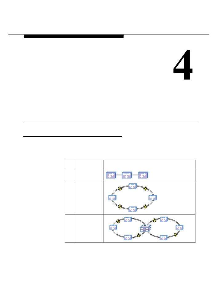
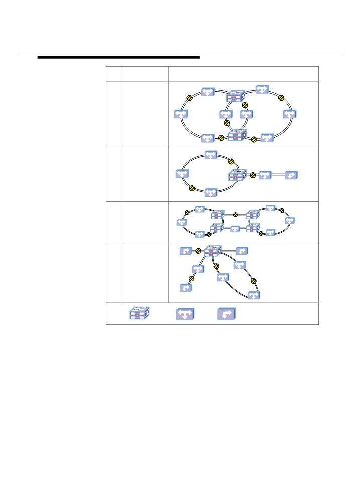
Chain and ring are two basic structures of the transmission network. Various
complicated network structures can derive from them in practice, as shown in Table
4-1.
Table 4-1 Basic service application
Networking
Topology
mode
1
Chain
2
Ring
3
Tangent rings
4-1
Networking
Networking
Topology
mode
4
Intersection
rings
5
Ring with chain
6
DNI
7
Hub composed
of ring and
chain
MADM
ADM
TM
Legend:
4-2
Networking
4.2 Application of Ethernet Service
With the capability of accessing Ethernet service integrated into the SDH platform, the
OptiX OSN 3500 can transmit both the voice service and data service. The OptiX
OSN 3500 supports service convergence and L2 switching, as well as the VLAN
function specified in IEEE 802.1Q. It also supports the L2 VPN service. With the
special frame format, the OptiX OSN 3500 can be deployed in the fields such as
MPLS, VLAN and L2 MPLS VPN, satisfying the user’s requirements for private line
and network.
1. Transparent transmission of the point-to-point Ethernet service in the
chain
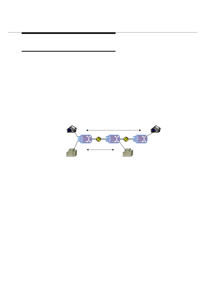
The OptiX OSN 3500 can be deployed in the chain network for point-to-point
transparent transmission of the Ethernet services, as shown in Figure 4-3. In this
figure, service A is transparently transmitted from Ethernet Port 1 of NE1 to Port 1 of
NE3, passing through VC-Trunk A. Service B is transparently transmitted from the
Ethernet Port 2 of NE1 to Port 1 of NE2, passing through VC-Trunk B. The services A
and B can be of either FE service or GE service.
VC-Trunk A
NE1
NE2
NE3
Port 1
Port 1
Port 2
Port 1
VC-Trunk B
Figure 4-3 Point-to-point transparent transmission of Ethernet service (in a chain)
2. VLAN convergence of Ethernet service in the chain
Supporting the VLAN function specified in IEEE802.1Q, the OptiX OSN 3500
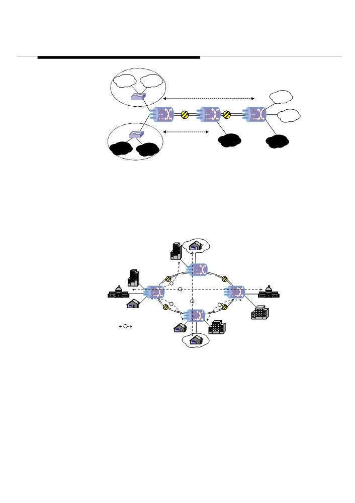
provides private network service. It performs flow classification to services according
to the Ethernet port and VLAN ID. Up to eight IEEE802.1P-compliant priorities can be
set according to the flow classification result. The OptiX OSN 3500 isolates services
of different users through VLAN to achieve security purpose. As shown in Figure 4-4,
VLAN 1 and VLAN2 of Company A share VC-Trunk 1 with VLAN 2 of Company B,
and the services on VLAN 1 of Company B are transmitted through VC-Trunk 2.
4-3
Networking
VLAN 1
VLAN 2
Company A
VC-Trunk 1
Lanswitch
VLAN 1
NE1
NE2
NE3
Port 1
Port 1
Port 2
VLAN 2
Port 2
Port 1
VC-Trunk 2
Port 3
Lanswitch
VLAN 1
VLAN 2
VLAN 1
VLAN 2
Company B
Figure 4-4 Port and VLAN-based flow classification and convergence (in a chain)
3. Transparent transmission of the point-to-point Ethernet service in the
ring
In the ring networking application, as the Ethernet service is provided with a perfect
SDH self-healing ring (SHR) protection scheme, its reliable transmission is
guaranteed. As shown in Figure 4-5, the Ethernet services of different nodes are
transmitted to the destination node through their respective VC-Trunks.
NE 4
1
4
NE 1
SHR NE 3
5
2
3
NE 2
n
VC Trunk
Figure 4-5 Point-to-point transparent transmission of Ethernet service (in a ring)
4. VLAN convergence of Ethernet service in the ring
The Ethernet service accessed at different nodes can be converged to one node and
sent to a certain port for transmission as required. As shown in Figure 4-6, flow
classification is performed to the Ethernet service according to the port and VLAN ID
to distinguish different VLANs that Company A and B belong to respectively. Up to
4-4
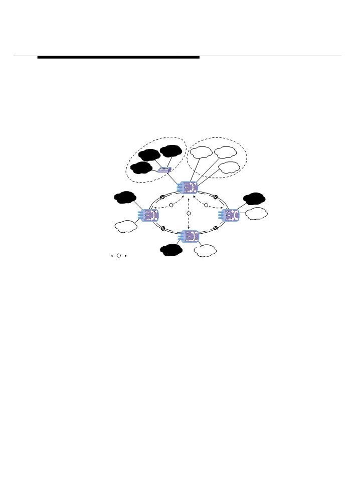
Networking
eight IEEE802.1P-compliant priorities can be set according to the flow classification
result. The OptiX OSN 3500 isolates services of different users through VLAN to
achieve security purpose. In the figure below, VLAN 1 of Company A shares a
VC-Trunk with VLAN 1 of Company B, and VLAN 2 of Company A shares a VC-Trunk
with VLAN 2 of Company B, and VLAN 3 of Company A shares a VC-Trunk with
VLAN 3 of Company B.
All services of Company A are converged to NE1 and output from an FE/GE interface
to Lanswitch for processing.
Headquarters of
Headquarters of
Company A
Company B
VLAN 3
VLAN 1
VLAN 2
VLAN 2
VLAN 1
VLAN 3
NE 1
VLAN 1
VLAN 3
NE 2
1
3
NE 4
2
VLAN 3
Branch
Branch
SHR
VLAN 1
NE 3
VLAN 2
VLAN 2
n
VC Trunk
Branch
Figure 4-6 VLAN convergence of Ethernet service (in a ring)
5. L2 switching of Ethernet service
The OptiX OSN 3500 supports L2 switching of the accessed Ethernet data, which can
be transferred according to their destination Media Access Control (MAC) addresses.
For example:
As shown in Figure 4-7, respective LANs of Company A and B are connected to four
nodes. The Ethernet service between the nodes is not of a fixed point-to-point type.
For example, a user of Company A connecting to NE3 may want to communicate with
users of Company A connecting to other three NEs. That is, the flow direction of
services is not definite. The Ethernet L2 switching function provided by the OptiX OSN
3500 can be employed to solve such a problem. For example, an Ethernet MAC
address transfer table will be formed in the system when relevant settings are made to
NE3. With the self study function of the system, this table can be updated periodically.
Then, according to their destination addresses, the data of Company A and B
accessed at NE3 will be transmitted to their destinations via checking the transfer
table and selecting corresponding VC-Trunks or sharing the same VC-Trunk. By this
way, the system configuration is significantly simplified and the bandwidth utility is
4-5