HUAWEI OptiX OSN 8800 T64/T32 Intelligent Optical Transport Platform. Product Description - part 30
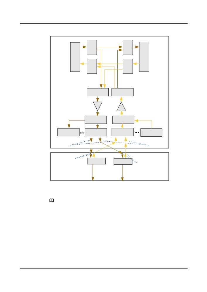
Figure 7-38 Schematic diagram of the split of optical and electrical NEs (Colorless)
W
R
NE1
S
D
M
U
F
9
9
F
I
I
U
R
W
U
D
S
U
M
9
9
RDU9
WSM9
OA
OA
DM1~DM 9
AM1~AM 9
WSD 9
WSM9
Drop 73~80
Drop 1~9
Add 1~9
Add 73~80
WSD9
WSD9
WSM9
WSM9
OCh
OCh
NE2
OCh
OTU
OTU
OCh
NOTE
When there is no optical path between two or more NEs, the Ethernet ports of the NEs can be used to
achieve the extended ECC communication. By default, the NE takes the auto-extended ECC
communication. When more than eight Huawei devices need to use the extended ECC communication, the
manually extended ECC communication must be used instead. See the "Setting Manually Extended ECC
Communication" of the Commissioning Guide of the OptiX OSN 8800 for details.
In the case that optical and electrical NEs are not split, ASON NEs can only take the OTU or
FIU board as the edge points and the matching TE link is generated when a board is added. In
the case that optical and electrical NEs are split, the multiplexer and demultiplexer boards or
another optical-layer board can be considered as the edge points of the optical NE. In this case,
when an intra-NE fiber connection is created between the optical port on the multiplexer and
demultiplexer boards and the optical port on the OTU board of the electrical NE, an intra-NE
link that carries OCh signals can be generated.
312
The ASON software processes stations where optical and electrical NEs are split and not split
in different modes. In the case of a station where optical and electrical NEs are split, the
connections between the optical NE and the electrical NE are described as intra-NE links. In
this case, a complete TE link is formed by the OMS TE links between upstream and downstream
stations and the intra-NE links at one station.
NOTE
The multiplexer and demultiplexer board and OTU board at the NE edges configure each other as the link
far end to form an abstract OMS TE link. The link is then used for creating optical-layer services.
After optical and electrical NEs are split at a station, bidirectional fiber connections and link far ends of
the optical and electrical NEs must be configured correctly according to the planning.
After optical and electrical NEs are split at a station, perform configurations on the U2000 to ensure proper
communication between optical NEs and electrical NEs and successful creation of TE links. For details on
how to perform the configurations, see Configuring a Station with Separate Optical and Electrical NEs.
The U2000 can create and manage optical-layer ASON services based on the split of optical and
electrical NEs, including creation, reroute, optimization, deletion, and pre-calculation of various
SLA services, and the conversion between static ASON and dynamic services. The operation
methods are the same as those of the services not based on the split of optical and electrical NEs.
NOTE
The electrical regeneration boards and the optical-layer boards must be installed on the same optical NE.
The total number of subracks of an optical NE cannot exceed 24 and the total number of wavelengths that
traverse electrical regeneration boards cannot exceed 32.
For separate optical and electrical NEs, active and standby system control boards must be used in the master
subracks of the optical and electrical NEs.
NOTE
Two regeneration boards need to be used to bidirectionally regenerate services if each of them can
regenerate services unidirectionally. The two regeneration boards must be installed in paired slots.
The LSXR and TN54NS3 board require one slot. The principles for configuring the LSXR and TN54NS3
boards are as follows:
l OptiX OSN 8800 T32: The LSXR and TN54NS3 boards for transmitting and receiving the same
wavelength must be installed in IU1 and IU2, IU3 and IU4, IU5 and IU6, IU7 and IU8, IU12 and IU13,
IU14 and IU15, IU16 and IU17, IU18 and IU19, IU20 and IU21, IU22 and IU23, IU24 and IU25, IU26
and IU27, IU29 and IU30, IU31 and IU32, IU33 and IU34, or IU35 and IU36.
l OptiX OSN 8800 T64: The LSXR and TN54NS3 boards for transmitting and receiving the same
wavelength must be installed in IU1 and IU2, IU3 and IU4, IU5 and IU6, IU7 and IU8, IU11 and IU12,
IU13 and IU14, IU15 and IU16, IU17 and IU18, IU19 and IU20, IU21 and IU22, IU23 and IU24, IU25
and IU26, IU27 and IU28, IU29 and IU30, IU31 and IU32, IU33 and IU34, IU35 and IU36, IU37 and
IU38, IU39 and IU40, IU41 and IU42, IU45 and IU46, IU47 and IU48, IU49 and IU50, IU51 and IU52,
IU53 and IU54, IU55 and IU56, IU57 and IU58, IU59 and IU60, IU61 and IU62, IU63 and IU64, IU65
and IU66, IU67 and IU68.
The TN12LSXLR board requires two slots. The principles for configuring the TN12LSXLR board are as
follows:
l OptiX OSN 8800 T32: The TN12LSXLR boards for transmitting and receiving the same wavelength
must be installed in IU2 and IU4, IU6 and IU8, IU13 and IU15, IU17 and IU19, IU21 and IU23, IU25
and IU27, IU30 and IU32, or IU34 and IU36.
l OptiX OSN 8800 T64: The TN12LSXLR boards for transmitting and receiving the same wavelength
must be installed in IU2 and IU4, IU6 and IU8, IU12 and IU14, IU16 and IU18, IU20 and IU22, IU24
and IU26, IU28 and IU30, IU32 and IU34, IU36 and IU38, IU40 and IU42, IU46 and IU48, IU50 and
IU52, IU54 and IU56, IU58 and IU60, IU62 and IU64, IU66 and IU68.
313
7.5.18 ASON Services Traversing Third-Party Equipment
The ASON software enables ASON services to traverse third-party equipment between Huawei
ASON nodes, and therefore enables end-to-end service management and monitoring.
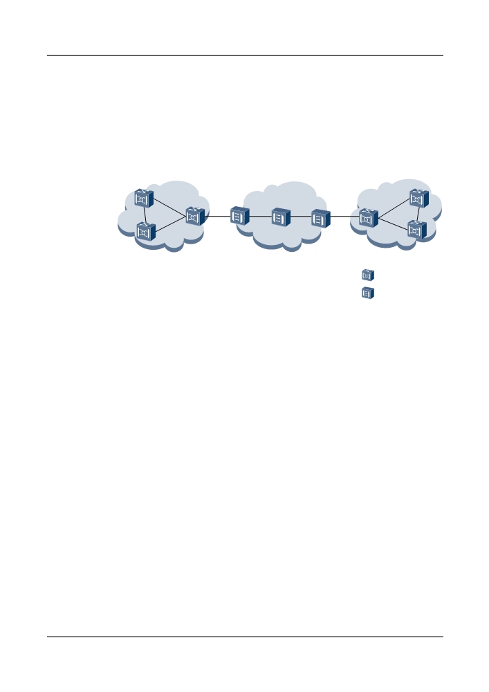
Figure 7-39 shows interconnection between Huawei NG WDM equipment and third-party
equipment on the client side.
Figure 7-39 Client-side interconnection between Huawei NG WDM equipment and third-party
equipment
NG WDM ASON
Third-party
NG WDM ASON
network
network
network
ASON NE
Third-party NE
On a network, third-party equipment terminates the OTUk layer and ASON nodes cannot detect
OTUk-layer alarms but only ODUk-layer alarms. Then link status cannot be accurately detected.
When the service boards on third-party equipment does not support rate adaptation, the ASON
service rate cannot be adjusted in an end-to-end mode. To resolve these issues, Huawei ASON
software enables ASON services to traverse third-party equipment.
l The ASON nodes with third-party equipment in between detect status of the links between
themselves according to the TCM-layer alarms, and trigger service rerouting if required.
l The OTUk rate for the ports connected to third-party equipment cannot be adjusted. This
prevents service interruption in case of an end-to-end rate adjustment failure.
ASON services can traverse third-party equipment on the following conditions:
l The third-party equipment supports access of OTUk signals.
l The third-party equipment transparently transmits the complete ODUk-layer signals from
the WDM-side ports on the OTU boards of Huawei NG WDM equipment.
l The third-party equipment processes TCM-layer signals in line with the standard.
l No ODUk cross-connections are configured on the service paths on the third-party
equipment (only regeneration is allowed).
l The third-party equipment does not use the TCM layer that has already been used by Huawei
ASON nodes.
l The TCM layer used by third-party equipment does not repeat the TCM layers in other
configurations.
314
7.6 OCS ASON Feature
The OptiX OSN series products of Huawei can provide the OCS ASON function after the ASON
software is loaded.
7.6.1 End-to-End Service Configuration
The ASON network supports end-to-end service configuration, which is very convenient.
The ASON supports both SDH permanent connections and end-to-end ASON services. To
configure an ASON service, you only need to specify its source node, sink node, bandwidth
requirement, and protection level. Service routing and cross-connection at intermediate nodes
are all automatically completed by the network. You can also set explicit node, excluded node,
explicit link and excluded link to constrain the service routing.
Compared with the service configuration of SDH networks, it fully utilizes the routing and
signaling functions of the ASON NEs and thus it is convenient to configure services. For
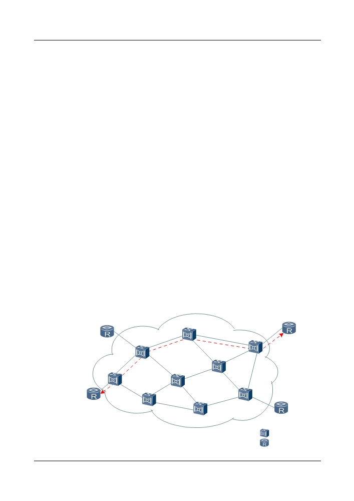
example, consider the configuration of a 155 Mbit/s ASON service between A and I in Figure
1. The network automatically finds the A-D-E-I route and configures cross-connection at nodes
A, D, E and I. Although there is more than one route from A to I, the network calculates the best
route according to the configured algorithm. It is assumed that A-D-E-I is the best route.
The service is created as follows:
l Choose the bandwidth granularity.
l Choose the server level.
l Choose the source node.
l Choose the sink node.
l Create the service.
Figure 7-40 End-to-end service configuration
R4
R1
E
I
D
F
C
A
B
H
G
R2
R3
:ASON NE
:User Equipment
315
7.6.2 Mesh Networking Protection and Restoration
The ASON provides mesh networking protection to enhance service survivability and network
security.
The ASON provides mesh networking protection to enhance service survivability and network
security.
As a main networking mode of ASON, mesh features high flexibility and scalability. Compared
with the traditional SDH networking mode, the mesh networking does not need to reserve 50%
bandwidth. Thus, it can save bandwidth resources to satisfy increasingly large bandwidth
demand. In addition, this networking mode also provides more than one recovery route for each
services so it can best utilize the network resources and enhance the network security.
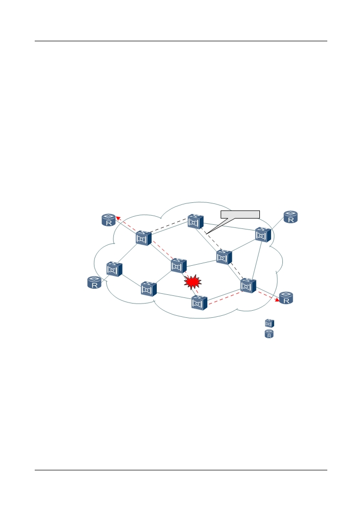
As shown in Figure 7-41, when the C-G link fails, to restore the service, the network calculates
another route from D to H and creates a new LSP to transmit the service.
Figure 7-41 Trail restoration
Recovery route
R4
R1
E
I
D
F
C
A
B
H
G
R2
R3
:ASON NE
:User Equipment
7.6.3 SLA Classification of Services
The ASON network can provide services of different QoS to different clients.
The service level agreement (SLA) is used to classify services according to the service protection,
as listed in Table 7-15.
316

Table 7-15 Service level (SDH Service)
Servic
Protection and
Implementati
Switching Time
Rerouting Time
e
Restoration
on Means
Scheme
Diamo
Protection and
SNCP and
Switching time <
The rerouting time
nd
restoration
rerouting
50 ms
varies with the
service
network size,
capacity and
Gold
Protection and
MSP and
Switching time <
service types.
service
restoration
rerouting
50 ms
Silver
Restoration
Rerouting
-
service
Copper
No protection
-
-
-
service
No restoration
Iron
Preemptable
MSP
-
-
service
Table 7-16 lists details of the TE links used by ASON services.
Table 7-16 TE links used by ASON services
Service Level
Working
Protection
Non-Protection
Resource
Resource of TE
Resource of TE
of TE Link
Link
Link
Diamond
Service creation
Not used
Not used
Used
service
Service rerouting
Not used
Used when the
Used with the
resource is not
priority
enough
Service optimization
Not used
Not used
Used
Gold
Service creation
Used with
Not used
Used when the
service
the priority
resource is not
enough
Service rerouting
Used with
Used when the
Used when the
the priority
resource is not
resource is not
enough
enough
Service optimization
Used with
Not used
Used when the
the priority
resource is not
enough
Silver
Service creation
Not used
Not used
Used
service
317

Service Level
Working
Protection
Non-Protection
Resource
Resource of TE
Resource of TE
of TE Link
Link
Link
Service rerouting
Not used
Used when the
Used with the
resource is not
priority
enough
Service optimization
Not used
Not used
Used
Copper
Service creation
Not used
Not used
Used
service
Service optimization
Not used
Not used
Used
Iron
Service creation
Not used
Used with the
Used when the
service
priority
resource is not
enough
Service optimization
Not used
Used with the
Used when the
priority
resource is not
enough
7.6.4 Diamond Services
Diamond services have the best protection ability. When there are enough resources in the
network, diamond services provide a permanent 1+1 protection. Diamond services are applicable
to voice and data services, VIP private line, such as banking, security and aviation.
A diamond service is a service with 1+1 protection from the source node to the sink node. It is
also called a 1+1 service. For a diamond service, there are two different LSPs available between
the source node and the sink node. The two LSPs should be as separate as possible. One is the
working LSP and the other is the protection LSP. The same service is transmitted to the working
LSP and the protection LSP at the same time. If the working LSP is normal, the sink node receives
the service from the working LSP; otherwise, from the protection LSP.
Figure 7-42 shows a diamond service.
318
Figure 7-42 Diamond Services
Working LSP
R4
R1
E
I
D
F
A
C
B
H
G
R2
R3
Protection LSP
:ASON NE
:User equipment
There are three types of diamond services.
l Permanent 1+1 diamond service: rerouting is triggered once an LSP fails.
l Rerouting 1+1 diamond service: rerouting is triggered only when both LSPs fail.
l Non-rerouting diamond service: rerouting is never triggered.
Table 7-17 lists the attributes of the permanent 1+1 diamond service.
Table 7-18 lists the attributes of the rerouting 1+1 diamond service.
Table 7-19 lists the attributes of the non-rerouting 1+1 diamond service.
Table 7-17 Attributes of the permanent 1+1 diamond services
Attribute
Permanent 1+1 Diamond Service
Requirements for
Sufficient non-protection resources are available between the
creation
source node and the sink node.
Protection and
If the resources are sufficient, two LSPs are always available for a
restoration
permanent 1+1 diamond service. One is the active LSP and the
other is the standby LSP.
Rerouting
l Supports rerouting lockout.
l Supports rerouting priority.
l Supports three rerouting policies:
- Use existing trails whenever possible
- Do not use existing trails whenever possible
- Best route
319

Attribute
Permanent 1+1 Diamond Service
Revertive
Supports Automatically Revertive, Non-Revertive, and
Scheduled revertive.
l After the automatically revertive diamond service is rerouted,
the service is automatically reverted to the original path if the
fault in the original path is rectified.
l After the scheduled revertive diamond service is rerouted, the
user can set the service to be reverted to the original path at a
specific future time (ranging from 10 minutes to 30 days) on the
NMS if the fault in the original path is rectified.
l After the non-revertive diamond service is rerouted, the service
is not reverted to the original route after the fault is rectified.
NOTE
The original route is the route before rerouting but may not be the original
route set up when the ASON trail is created.
Service migration
l Supports migration between diamond services and permanent
SNCP connections.
l Supports migration between diamond services and gold
services.
l Supports migration between diamond services and silver
services.
l Supports migration between diamond services and copper
services.
Service switching
Supports manual switching.
Service optimization
Supports service optimization.
Service association
Does not support service association.
ASON server trail
Support diamond ASON server trails.
Alarms to trigger
R_LOS, R_LOF, B2_EXC, B2_SD, MS_AIS, MS_RDI, AU_AIS,
rerouting
B3_EXC (can be set), B3_SD (can be set)
Table 7-18 Attributes of the rerouting 1+1 diamond service
Attribute
Rerouting 1+1 Diamond Service
Requirements for
Sufficient non-protection resources are available between the source node
creation
and the sink node
Protection and
l When the standby LSP fails, services are not switched. Rerouting is
restoration
not triggered.
l When the active LSP fails, services are switched to the standby LSP
for transmission. Rerouting is not triggered.
l When both the active and the standby LSPs fail, rerouting is triggered
to create a new LSP to restore services.
320

Attribute
Rerouting 1+1 Diamond Service
Rerouting
l Supports rerouting lockout.
l Supports rerouting priority.
l Supports three rerouting policies:
- Use existing trails whenever possible
- Do not use existing trails whenever possible
- Best route
Revertive
Supports Automatically Revertive, Non-Revertive, and Scheduled
revertive.
l After the automatically revertive diamond service is rerouted, the
service is automatically reverted to the original path if the fault in the
original path is rectified.
l After the scheduled revertive diamond service is rerouted, the user can
set the service to be reverted to the original path at a specific future
time (ranging from 10 minutes to 30 days) on the NMS if the fault in
the original path is rectified.
l After the non-revertive diamond service is rerouted, the service is not
reverted to the original route after the fault is rectified.
NOTE
The original route is the route before rerouting but may not be the original route
set up when the ASON trail is created.
Service
l Supports migration between diamond services and permanent SNCP
migration
connections.
l Supports migration between diamond services and gold services.
l Supports migration between diamond services and silver services.
l Supports migration between diamond services and copper services.
Service
Supports manual switching.
switching
Service
Supports service optimization.
optimization
Service
Does not support service association.
association
ASON server
Support diamond ASON server trails.
trail
Alarms to trigger
R_LOS, R_LOF, B2_EXC, B2_SD, MS_AIS, MS_RDI, AU_AIS,
rerouting
B3_EXC (can be set), B3_SD (can be set)
321

Table 7-19 Attributes of the non-rerouting 1+1 diamond service
Attribute
Non-rerouting 1+1 diamond service
Requirements for
Sufficient non-protection resources are available between the source node
creation
and the sink node
Protection and
l When the active LSP fails, services are switched to the standby LSP
restoration
for transmission. Rerouting is not triggered.
l When the standby LSP fails, services are not switched. Rerouting is
not triggered.
l When both the active and the standby LSPs fail, rerouting is not
triggered.
Service
l Supports migration between diamond services and permanent SNCP
migration
connections.
l Supports migration between diamond services and gold services.
l Supports migration between diamond services and silver services.
l Supports migration between diamond services and copper services.
Service
Supports manual switching.
switching
Service
Supports service optimization.
optimization
Service
Does not support service association.
association
ASON server
Support diamond ASON server trails.
trail
7.6.5 Gold Services
Gold services are applicable to voice and significant data services. Compared with diamond
services, gold services have greater bandwidth utilization.
A gold service needs only one LSP. This LSP must use working resource of TE links or non-
protection resource of TE links. When a fiber on the path of a gold service is cut, the ASON
triggers MSP switching to protect the service at first. If the multiplex section protection fails,
the ASON triggers rerouting to restore the service.
As shown in Figure 7-43, a gold service can be configured from A to I.
322