Yamaha XV1700P, XV1700PC. Service Manual - part 9
3 - 24
CHK
ADJ
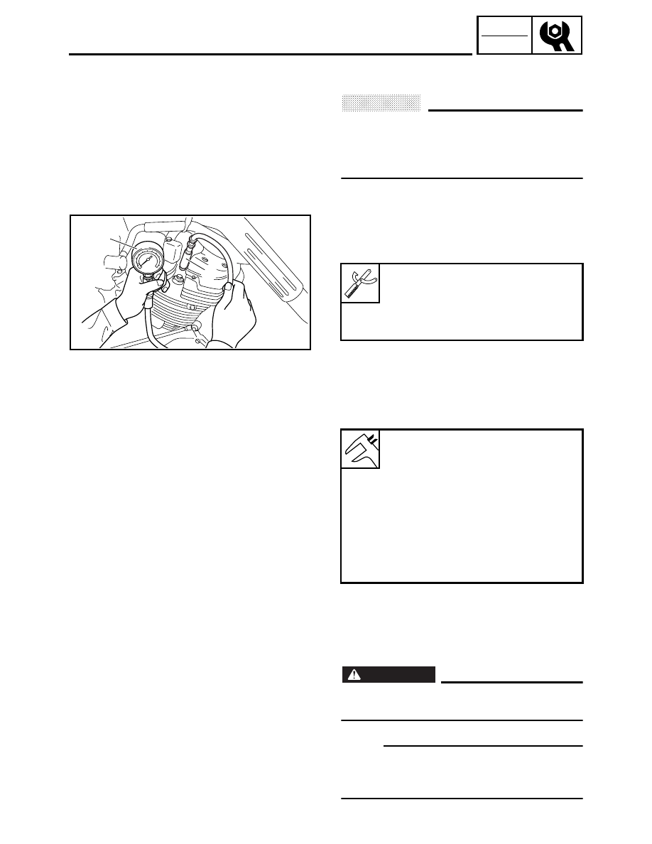
MEASURING THE COMPRESSION PRESSURE
7. Remove:
• spark plug
CAUTION:
_
Before removing the spark plugs, use com-
pressed air to blow away any dirt accumu-
lated in the spark plug wells to prevent it
from falling into the cylinders.
8. Install:
• compression gauge set 14/18 mm
1
• compression gauge adapter 12 mm
2
Compression gauge set 14/18 mm
YU-33223
Compression gauge adapter
12 mm
YU-33223-3
2
1
9. Measure:
• compression pressure
Out of specification
→
Refer to steps (c)
and (d).
▼▼▼
▼
▼ ▼▼▼
▼
▼ ▼▼▼
▼
▼ ▼▼▼
▼
▼ ▼▼▼
▼
▼ ▼▼▼
▼
▼▼▼
a. Set the main switch to “ON”.
b. With the throttle wide open, crank the
engine until the reading on the compression
gauge stabilizes.
WARNING
_
To prevent sparking, ground all spark plug
leads before cranking the engine.
NOTE:
_
The difference in compression pressure
between cylinders should not exceed 100 kPa
(1 kg/cm
2
, 14 psi).
Compression pressure (at sea
level)
Minimum
1,040 kPa
(10.4 kg/cm
2
, 148 psi)
Standard
1,200 kPa
(12.0 kg/cm
2
, 171 psi)
Maximum
1,340 kPa
(13.4 kg/cm
2
, 191psi)