Yamaha XV1700P, XV1700PC. Service Manual - part 7
 

  Index      Manuals     Yamaha XV1700P, XV1700PC. Service Manual


Search            copyright infringement  


Content      ..     5      6      7      8     ..


Yamaha XV1700P, XV1700PC. Service Manual - part 7


2 - 42

SPEC

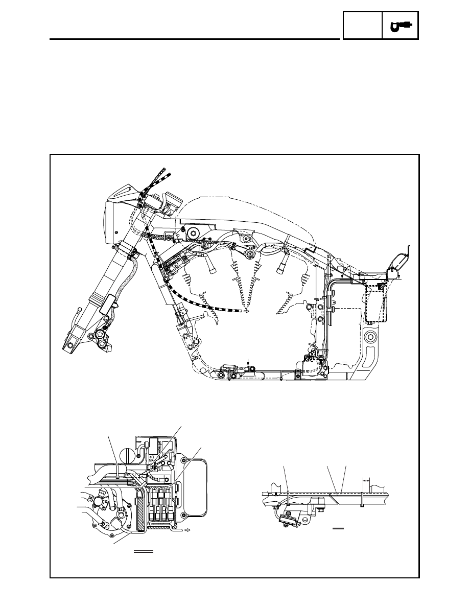
CABLE ROUTING

Ë

Fasten the decompression solenoid lead, speed sensor lead, cylinder identification sensor lead, sidestand
switch lead, crankshaft position sensor lead, neutral switch lead, and fuel pump lead with a plastic band.

Ì

Position the gray mark on the starter motor lead at the center of the bolt. Fit the starter motor lead and sid-
estand switch lead into the groove in the frame, and then fasten them with a plastic locking tie.

Í

10 

~

 30 mm (0.4 

~

 1.2 in)

A

A

B

B

2

3

A-A

1

4

3

Í

Ì

Ê

É

È

Ë

2 - 43

SPEC

CABLE ROUTING

1

Fuse box

2

ECU lead

3

Battery

4

Starter motor lead

5

ECU ground lead

6

Fuel tank/air filter breather hose

7

Fuel tank/air filter drain hose

8

Regulator lead

9

Horn lead

0

Rear brake light switch lead

A

Cut-off relay

B

Turn signal relay

C

Headlight relay

È

Clamp the fuel tank/air filter breather hose, and
fuel tank/air filter drain hose with a plastic clamp.

É

45 ~ 60 degrees

Ê

15 ~ 30 degrees

C

C

B

B

2

4

5

4 6

7

A-A

B-B

C-C

D

8

9

0

6

7

È

A

A

D

1

É

Ê

3

3

B

A

1

C

2 - 44

SPEC

CABLE ROUTING

1

Roll over valve

2

Fuel tank breather hose

3

Fuel hose joint 1

4

Fuel hose

5

Fuel inlet hose

6

Fuel outlet hose

7

Fuel hose joint 2

8

Fuel hose

9

Fuel pump coupler

0

Sub fuel tank

A

Fuel tank drain hose 

B

Fuel tank/air filter breather hose

C

Ignition coil 1

È

Make sure that the white paint mark is facing for-
ward.

A-A

B

A

A

B

C

A

B

4

1

2

3

4

5

6

7

8

9

0

È

B

A

2 - 45

SPEC

CABLE ROUTING

1

Oil temperature sensor

2

Fuel hose

3

Spark plug cap (ignition coil 1-R
spark plug lead)

4

Injector lead

5

Throttle position sensor lead

6

Intake air pressure sensor 1

7

Intake air temperature sensor 
coupler

8

Intake air pressure sensor lead

9

Intake air pressure sensor 2

0

Throttle cables

A

Brake hose

B

Spark plug cap (ignition coil 2-R
spark plug lead)

C

Engine temperature sensor lead

D

Stator coil lead

E

Neutral switch lead

F

Speed sensor lead

G

Main wire harness

H

Ignition coil 1-R spark plug lead

I

Lean angle cut-off switch lead

J

Crankshaft position sensor lead

K

Sidestand switch lead

L

Starter motor lead

M

Horn 2 lead

C

C

B

B

A

A

A

0

A

9

8

7

6

5

4

3

2

1

F

E

D

C

B

J

I

M

L

K

G

H

G

H

G

2

A-A

B-B

C-C

A

Ø

Ò

Ó

Ï

Í

Ì

Ë

Ê

É

È

Ö

×

Ô

Õ

Ð

Ñ

Î

2 - 46

SPEC

CABLE ROUTING

È

To the battery box.

É

Fasten the main wire harness, and fuel hose
with a plastic locking tie to the frame.

Ê

Fasten the main wire harness, and spark plug
lead #3 with a plastic locking tie to the frame.

Ë

Fasten the throttle position sensor lead, engine
temperature sensor lead, and injector lead with
a plastic locking tie to the fuel delivery pipe.

Ì

Fasten the main wire harness, and spark plug
lead #3 with a plastic locking tie.

Í

Fasten the main wire harness, intake air pres-
sure sensor lead #2, ignition coil 1-R spark plug
lead, and intake air temperature sensor coupler
with a plastic locking tie.

Î

Fasten the rear brake light switch lead, and igni-
tion coil lead #2 with a plastic band.

Ï

Fasten the main wire harness, and intake vac-
uum hose with a plastic locking tie.

C

C

B

B

A

A

A

0

A

9

8

7

6

5

4

3

2

1

F

E

D

C

B

J

I

M

L

K

G

H

G

H

G

2

A-A

B-B

C-C

A

Ø

Ò

Ó

Ï

Í

Ì

Ë

Ê

É

È

Ö

×

Ô

Õ

Ð

Ñ

Î

2 - 47

SPEC

CABLE ROUTING

Ð

To the injector sub lead.

Ñ

To the engine temperature sensor.

Ò

10 

~

 30 mm (0.4 

~

 1.2 in)

Ó

Position the gray mark on the stator coil lead at
the center of the bolt, and then fasten it with a
plastic locking tie.

Ô

To the stator coil.

Õ

To the decompression solenoid, and cylinder
identification sensor.

Ö

To the neutral switch.

×

To the speed sensor.

Ø

Fasten the crankshaft position sensor lead, side-
stand switch lead, lean angle cut-off switch lead,
starter motor lead, and horn lead with a plastic
locking tie.

C

C

B

B

A

A

A

0

A

9

8

7

6

5

4

3

2

1

F

E

D

C

B

J

I

M

L

K

G

H

G

H

G

2

A-A

B-B

C-C

A

Ø

Ò

Ó

Ï

Í

Ì

Ë

Ê

É

È

Ö

×

Ô

Õ

Ð

Ñ

Î

2 - 48

SPEC

CABLE ROUTING

1

Ignition coil 2-R spark plug lead

2

Ignition coil 1-R spark plug lead

3

Main wire harness

4

Negative battery ground lead

5

Fuse box

6

Main fuse coupler

7

Positive battery lead

8

ECU

9

Fuel hose

0

Ignition coil 1-L spark plug lead

A

Ignition coil 2-L spark plug lead

È

40 

~

 60 mm (1.6 

~

 2.4 in)

1

2

3

4

8

0

A

5

6

7

9

È

2 - 49

SPEC

CABLE ROUTING

1

Canister (California only)

2

Canister purge hose (California only)

3

Intake vacuum hose

4

Liner control valve inlet hose

5

Liner control valve outlet hose

6

Throttle position sensor

7

Fuel hose

8

Throttle stop screw

9

Fuel inlet hose

0

Pressure regulator

A

A.I.S. vacuum hose

B

Silencer air filter case drain hose

2

1

B

A

7

0

7

9

8

7

3

6

5

4

3

2 - 50

SPEC

CABLE ROUTING

Canister (California only)

1

Canister charge hose

2

Canister purge hose

3

Starter motor lead

4

Canister

5

Fuel tank drain hose

6

Regulator lead

7

Horn lead

8

Rear brake light switch lead

È

To the fuel tank.

É

To the silencer air filter case.

Ê

To the throttle bodies.

A

A

B

B

C

A

A

B

B

C

1

2

8

7

6

5

2

1

2

5

1

1

2

3

4

5

C

A-A

B-B

È

É

Ê

3 - 1

CHK

ADJ

EAS00036

PERIODIC CHECKS AND ADJUSTMENTS

INTRODUCTION

This chapter includes all information necessary to perform recommended checks and adjustments.
If followed, these preventive maintenance procedures will ensure more reliable vehicle operation, a
longer service life and reduce the need for costly overhaul work. This information applies to vehicles
already in service as well as to new vehicles that are being prepared for sale. All service technicians
should be familiar with this entire chapter.

PERIODIC MAINTENANCE CHART FOR THE EMISSION CONTROL 
SYSTEM

No.

ITEM

ROUTINE

INITIAL

ODOMETER READINGS

600 mi

(1,000 km) 

or

1 month

4,000 mi

(7,000 km) 

or

6 months

8,000 mi

(13,000 km) 

or

12 months

12,000 mi

(19,000 km) 

or

18 months

16,000 mi

(25,000 km) 

or

24 months

20,000 mi

(31,000 km)


or

30 months

1

*

Valve clearance
(See page 3-11.)

• Check valve clearance when engine is cold.
• Adjust if necessary.

Every 16,000 

mi

 (25,000 km)

2

*

Spark plugs
(See page 3-20.)

• Check condition. 
• Adjust gap and clean. 
• Replace at 8,000 mi (13,000 km) or 

12 months and thereafter every 8,000 mi 
(13,000 km) or 12 months.

Replace.

Replace.

3

*

Crankcase ventila-
tion system
(See page 3-38.)

• Check ventilation hose for cracks or damage. 
• Replace if necessary.

4

*

Fuel line
(See page 3-37.)

• Check fuel hose for cracks or damage.
• Replace if necessary.

5

*

Exhaust system
(See page 3-39.)

• Check for leakage. 
• Retighten if necessary. 
• Replace gasket(s) if necessary.

6

*

Electrical Fuel 
Injection System
(See page 3-15.)

• Check and adjust engine idle speed and syn-

chronization. 

• Adjust cable free play.

7

*

Evaporative 
Emission control 
system (For 
California only)

• Check control system for damage.
• Replace if necessary.

* Since these items require special tools, data and technical skills, have a Yamaha dealer perform the service.

INTRODUCTION/PERIODIC MAINTENANCE CHART

FOR THE EMISSION CONTROL SYSTEM

3 - 2

CHK

ADJ

GENERAL MAINTENANCE AND LUBRICATION CHART

GENERAL MAINTENANCE AND LUBRICATION CHART

No.

ITEM

ROUTINE

TYPE

INITIAL

ODOMETER READINGS

600 mi

(1,000 km) 

or

1 month

4,000 mi

(7,000 km) 

or

6 months

8,000 mi

(13,000 km) 

or

12 months

12,000 mi

(19,000 km) 

or

18 months

16,000 mi

(25,000 km) 

or

24 months

20,000 mi

(31,000 km)


or

30 months

1

Engine oil
(See page 3-27.)

• Change.

2

*

Engine oil filter 
cartridge

• Replace.

3

*

Air filter elements 
(See page 3-36.)

• Check condition and for 

damage.

• Replace if necessary.

4

*

Front brake
(See page 3-40.)

• Check operation and 

fluid leakage. (See 
NOTE page 3-3.)

• Correct if necessary.

Replace 

brake 

fluid.

5

*

Rear brake
(See page 3-41.)

• Check operation and 

fluid leakage. (See 
NOTE page 3-3.)

• Correct if necessary.

Replace 

brake 

fluid.

6

*

Clutch
(See page 3-35.)

• Check operation and 

free play.

• Correct if necessary.

7

*

Transfer case oil
(See page 3-32.)

• Check vehicle for leak-

age.

• Replace every 

16,000 mi (25,000 km) 
or 24 months.

SAE 80 API “GL-4” 
hypoid gear oil

Change.

Check.

Change.

8

*

Control cables
(See page 3-58.)

• Apply chain lube thor-

oughly.

Yamaha chain and 
cable lube or 
engine oil 10W-30

9

*

Rear arm pivot 
bearing
(See page 4-86.)

• Check bearing assem-

bly for looseness.

• Moderately repack 

every 16,000 mi 
(25,000 km) or 
24 months.

Lithium-soap-
based grease

Repack.

10

Brake and clutch 
lever pivot shafts
(See page 3-59.)

• Lubricate.
• Apply grease lightly.

Lithium-soap-
based grease (all-
purpose grease)

11

Brake pedal and 
shift pedal shafts
(See page 3-59.)

• Lubricate.
• Apply grease lightly.

Lithium-soap-
based grease (all-
purpose grease)

12 *

Sidestand pivot
(See page 3-59.)

• Check operation and 

lubricate.

• Apply grease lightly.

Lithium-soap-
based grease (all-
purpose grease)

13 *

Sidestand switch
(See page 3-59.)

• Check and clean or 

replace if necessary.

14 *

Front fork 
(See page 3-52.)

• Check operation and for 

leakage.

15 *

Steering bearings
(See page 3-50.)

• Check bearing assem-

bly for looseness.

• Moderately repack 

every 16,000 mi 
(25,000 km) or 
24 months.

Lithium-soap-
based grease (all-
purpose grease)

Repack.

16 *

Wheel bearings
(See page 4-4.)

• Check bearings for 

smooth rotation.

1

2

3

3 - 3

CHK

ADJ

GENERAL MAINTENANCE AND LUBRICATION CHART

* Since these items require special tools, data and technical skills, have a Yamaha dealer perform the service.

NOTE:

From 24,000 mi (37,000 km) or 36 months, repeat the maintenance intervals starting from 4,000 mi
(7,000 km) or 6 months. 

NOTE:

• Air filters

• This model’s air filters are equipped with disposable oil-coated paper elements, which must not

be cleaned with compressed air to avoid damaging them.

• The air filter elements need to be replaced more frequently when riding in unusually wet or dusty

areas.

• Hydraulic brake service

• After disassembling the brake master cylinders and calipers, always change the fluid. Regularly

check the brake fluid levels and fill the reservoirs as required.

• Every two years replace the internal components of the brake master cylinders and calipers, and

change the brake fluid.

• Replace the brake hoses every four years and if cracked or damaged. 

17 *

Rear suspension 
link pivots
(See page 4-86.)

• Lubricate.
• Apply grease lightly.

Lithium-soap-
based grease

18 *

Drive belt
(See page 3-47.)

• Check belt tension.
• Adjust if necessary.

Every 2,500 mi (4,000 km)

No.

ITEM

ROUTINE

TYPE

INITIAL

ODOMETER READINGS

600 mi

(1,000 km) 

or

1 month

4,000 mi

(7,000 km) 

or

6 months

8,000 mi

(13,000 km) 

or

12 months

12,000 mi

(19,000 km) 

or

18 months

16,000 mi

(25,000 km) 

or

24 months

20,000 mi

(31,000 km)


or

30 months

3 - 4

CHK

ADJ

SEAT AND SIDE COVERS

EAS00038

SEAT AND SIDE COVERS

4

5

3

1

2

6

T


R

.

.

10 Nm (1.0 m 


kg, 7.2 ft


Ib)

T


R

.

.

10 Nm (1.0 m 


kg, 7.2 ft


Ib)

T


R

.

.

10 Nm (1.0 m 


kg, 7.2 ft


Ib)

T


R

.

.

10 Nm (1.0 m 


kg, 7.2 ft


Ib)

T


R

.

.

4 Nm (0.4 m


 kg, 2.9 ft 

 Ib)

T


R

.

.

7 Nm (0.7 m


 kg, 5.1 ft 

 Ib)

Order

Job/Part

Q’ty

Remarks

Removing the seat and side covers

Remove the parts in the order listed. 

1

Seat

1

2

Cover

1

3

Tool kit

1

4

Left side cover 1

1

5

Left side cover 2

1

6

Right side cover

1

For installation, reverse the removal 
procedure.

3 - 5

CHK

ADJ

HEADLIGHT AND METER ASSEMBLIES

1

3

4

5

2

T


R

.

.

7 Nm (0.7 m


 kg, 5.1 ft 

 Ib)

T


R

.

.

8 Nm (0.8 m


 kg, 5.8 ft 

 Ib)

T


R

.

.

7 Nm (0.7 m


 kg, 5.1 ft 

 Ib)

T


R

.

.

23 Nm (2.3 m 


kg, 17 ft


Ib)

Order

Job/Part

Q’ty

Remarks

Removing the headlight and meter 
assemblies

Remove the parts in the order listed. 

1

Headlight lens unit

1

2

Wire harness (in the headlight body)

1

Disconnect.

3

Headlight body

1

4

Tachometer assembly

1

5

Speedometer assembly

1

For installation, reverse the removal 
procedure.

HEADLIGHT AND METER ASSEMBLIES

3 - 6

CHK

ADJ

BATTERY

BATTERY

6

4

3

5

1

2

Order

Job/Part

Q’ty

Remarks

Removing the battery

Remove the parts in the order listed.

Seat

Refer to “SEAT AND SIDE COVERS”.

1

ECU

1

2

Battery cover

1

3

Negative battery lead

1

4

Positive battery lead

1

5

Battery

1

6

Belt

1

For installation, reverse the removal 
procedure.

3 - 7

CHK

ADJ

FUEL TANK

FUEL TANK

5

(4)

2

1

4

3

6

T


R

.

.

7 Nm (0.7 m


 kg, 5.1 ft 

 Ib)

T


R

.

.

10 Nm (1.0 m 


kg, 7.2 ft


Ib)

Order

Job/Part

Q’ty

Remarks

Removing the fuel tank

Remove the parts in the order listed.

Seat

Refer to “SEAT AND SIDE COVERS”.

1

Air induction system cover

1

2

Air duct

1

3

Fuel hose joint 1

1

Disconnect.

4

Fuel hose joint 2

1

Disconnect.

5

Fuel tank breather hose

2

Disconnect.

6

Fuel tank

1

For installation, reverse the removal 
procedure.


Content      ..     5      6      7      8     ..