Yamaha XV1700P, XV1700PC. Service Manual - part 10
 

  Index      Manuals     Yamaha XV1700P, XV1700PC. Service Manual


Search            copyright infringement  


Content      ..     8      9      10      11     ..


Yamaha XV1700P, XV1700PC. Service Manual - part 10


3 - 40

CHK

ADJ

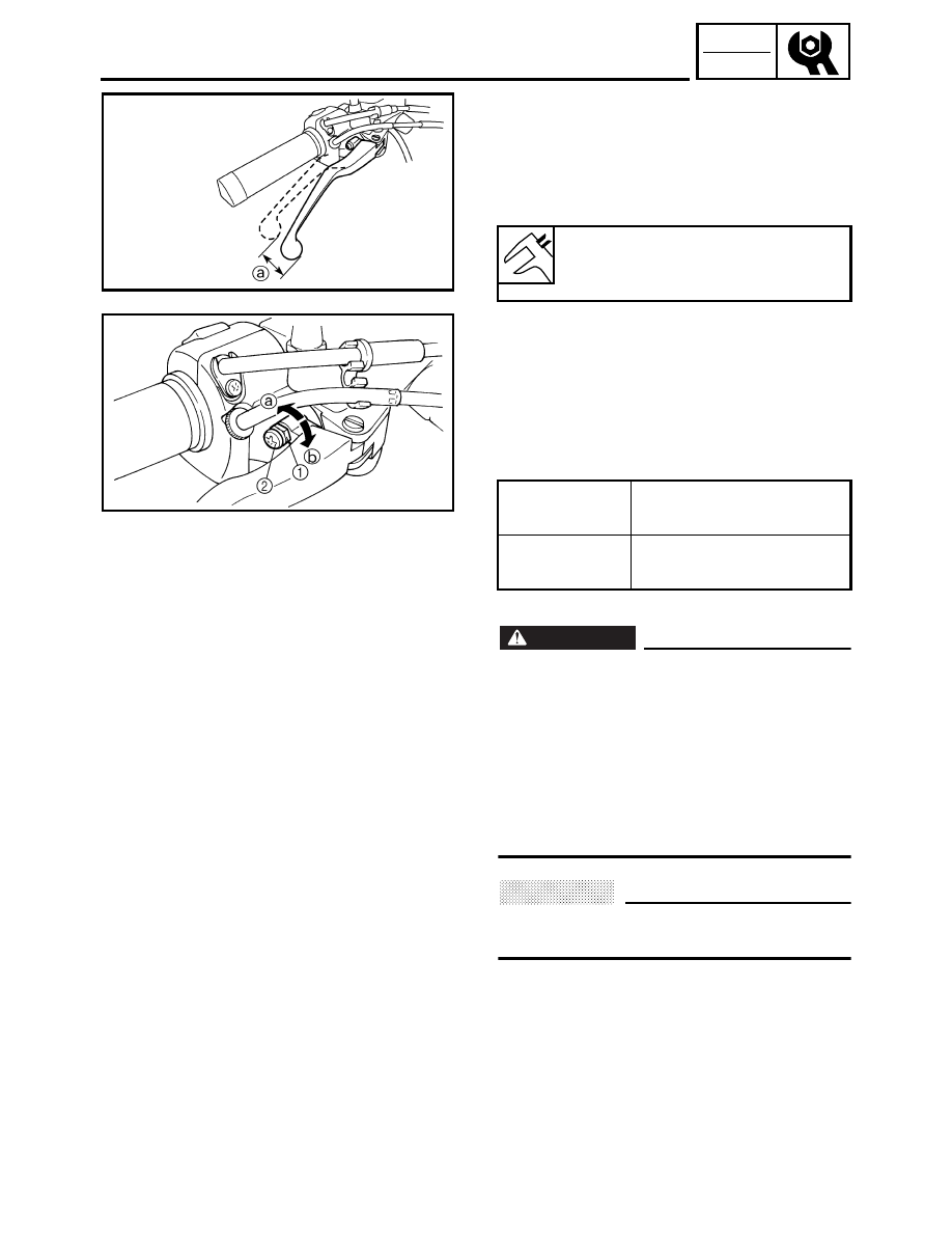
ADJUSTING THE FRONT BRAKE

EAS00108

CHASSIS

ADJUSTING THE FRONT BRAKE

1. Check: 

• brake lever free play 

a


Out of specification 

 Adjust.

2. Adjust: 

• brake lever free play

▼▼▼

▼ ▼▼▼

▼ ▼▼▼

▼ ▼▼▼

▼ ▼▼▼

▼ ▼▼▼

▼▼▼

a. Loosen the locknut 

1

b. Turn the adjusting screw 

2

 in direction 

a

or 

b

 until the specified brake lever free play

is obtained.

c. Tighten the locknut.

WARNING

A soft or spongy feeling in the brake lever
can indicate the presence of air in the brake
system. Before the vehicle is operated, the
air must be removed by bleeding the brake
system. Air in the brake system will consid-
erably reduce braking performance and
could result in loss of control and possibly
an accident. Therefore, check and, if neces-
sary, bleed the brake system. 

CAUTION:

After adjusting the brake lever free play,
make sure there is no brake drag. 

▲▲▲

▲ ▲▲▲

▲ ▲▲▲

▲ ▲▲▲

▲ ▲▲▲

▲ ▲▲▲

▲▲▲

Brake lever free play (at the end 
of the brake lever) 

2 ~ 5 mm (0.08 ~ 0.20 in)

Direction 

a

Brake lever free play is 
increased.

Direction 

b

Brake lever free play is 
decreased.

3 - 41

CHK

ADJ

EAS00110

ADJUSTING THE REAR BRAKE

1. Check: 

• brake pedal position 

(distance 

a

 from the top of the rider foot-

rest to the top of the brake pedal) 
Out of specification 

 Adjust.

2. Adjust: 

• brake pedal position

▼▼▼

▼ ▼▼▼

▼ ▼▼▼

▼ ▼▼▼

▼ ▼▼▼

▼ ▼▼▼

▼▼▼

a. Loosen the locknut 

1

b. Turn the adjusting bolt 

2

 in direction 

a

 or

b

 until the specified brake pedal position is

obtained.

WARNING

After adjusting the brake pedal position,
check that the end of the adjusting bolt 

c

is visible through the hole 

d

c. Tighten the locknut 

1

 to specification.

WARNING

A soft or spongy feeling in the brake pedal
can indicate the presence of air in the brake
system. Before the vehicle is operated, the
air must be removed by bleeding the brake
system. Air in the brake system will consid-
erably reduce braking performance and
could result in loss of control and possibly
an accident. Therefore, check and, if neces-
sary, bleed the brake system. 

Brake pedal position (from the 
top of the rider footrest to the top 
of the brake pedal) 

80 mm (3.2 in)

Direction 

a

Brake pedal is raised.

Direction 

b

Brake pedal is lowered.

T


R

.

.

Locknut 

16 Nm (1.6 m • kg, 11 ft • lb)

1

b

a

2

2

1

c

d

ADJUSTING THE REAR BRAKE

3 - 42

CHK

ADJ

ADJUSTING THE REAR BRAKE/

CHECKING THE BRAKE FLUID LEVEL

CAUTION:

After adjusting the brake pedal position,
make sure there is no brake drag. 

▲▲▲

▲ ▲▲▲

▲ ▲▲▲

▲ ▲▲▲

▲ ▲▲▲

▲ ▲▲▲

▲▲▲

3. Adjust: 

• rear brake light switch 

Refer to “ADJUSTING THE REAR BRAKE
LIGHT SWITCH”.

EAS00115

CHECKING THE BRAKE FLUID LEVEL

1. Stand the motorcycle on a level surface.

NOTE:

• Place the motorcycle on a suitable stand. 
• Make sure the motorcycle is upright. 

2. Check: 

• brake fluid level 

Below the minimum level mark 

a


 Add

the recommended brake fluid to the proper
level.

È

Front brake 

É

Rear brake

WARNING

• Use only the designated brake fluid.

Other brake fluids may cause the rubber
seals to deteriorate, causing leakage and
poor brake performance. 

• Refill with the same type of brake fluid

that is already in the system. Mixing
brake fluids may result in a harmful
chemical reaction, leading to poor brake
performance. 

• When refilling, be careful that water does

not enter the brake fluid reservoir. Water
will significantly lower the boiling point of
the brake fluid and could cause vapor
lock. 

Recommended brake fluid 

DOT 4

È

a

É

3 - 43

CHK

ADJ

CHECKING THE BRAKE FLUID LEVEL/

CHECKING THE FRONT BRAKE PADS/

CHECKING THE REAR BRAKE PADS

CAUTION:

Brake fluid may damage painted surfaces
and plastic parts. Therefore, always clean
up any spilt brake fluid immediately. 

NOTE:

In order to ensure a correct reading of the
brake fluid level, make sure the top of the
brake fluid reservoir is horizontal. 

EAS00120

CHECKING THE FRONT BRAKE PADS

The following procedure applies to all of the
brake pads. 
1. Operate the brake. 
2. Check: 

• front brake pad 

Wear indicator groove 

1

 almost disap-

peared 

 Replace the brake pads as a set. 

Refer to “REPLACING THE FRONT
BRAKE PADS” in chapter 4.

Brake pad wear limit 

a


0.5 mm (0.02 in)

EAS00118

CHECKING THE REAR BRAKE PADS

The following procedure applies to all of the
brake pads.
1. Operate the brake. 
2. Check: 

• rear brake pad 

Wear indicators 

1

 almost touch the brake

disc 

 Replace the brake pads as a set. 

Refer to “REPLACING THE REAR BRAKE
PADS” in chapter 4.

Brake pad wear limit 

a


0.8 mm (0.03 in)

a

1

1

3 - 44

CHK

ADJ

ADJUSTING THE REAR BRAKE LIGHT SWITCH/

CHECKING THE FRONT AND REAR BRAKE HOSES

EAS00128

ADJUSTING THE REAR BRAKE LIGHT 
SWITCH

NOTE:

The rear brake light switch is operated by
movement of the brake pedal. The rear brake
light switch is properly adjusted when the
brake light comes on just before the braking
effect starts. 

1. Check: 

• rear brake light operation timing 

Incorrect 

 Adjust.

2. Adjust: 

• rear brake light operation timing

▼▼▼

▼ ▼▼▼

▼ ▼▼▼

▼ ▼▼▼

▼ ▼▼▼

▼ ▼▼▼

▼▼▼

a. Hold the main body 

1

 of the rear brake light

switch so that it does not rotate and turn the
adjusting nut 

2

 in direction 

a

 or 

b

 until the

rear brake light comes on at the proper
time.

▲▲▲

▲ ▲▲▲

▲ ▲▲▲

▲ ▲▲▲

▲ ▲▲▲

▲ ▲▲▲

▲▲▲

Direction 

a

Brake light comes on 
sooner. 

Direction 

b

Brake light comes on 
later.

EAS00131

CHECKING THE FRONT AND REAR BRAKE 
HOSES

The following procedure applies to all of the
brake hoses and brake hose clamps.
1. Check: 

• brake hose 

Cracks/damage/wear 

 Replace.

2. Check: 

• brake hose clamp 

Loose 

 Tighten the clamp bolt.

3. Hold the motorcycle upright and apply the

brake several times.

3 - 45

CHK

ADJ

CHECKING THE FRONT AND REAR BRAKE HOSES/

BLEEDING THE HYDRAULIC BRAKE SYSTEM

4. Check: 

• brake hose 

Brake fluid leakage 

 Replace the dam-

aged hose. 
Refer to “FRONT AND REAR BRAKES” in
chapter 4.

È

Front

É

Rear

È

É

EAS00134

BLEEDING THE HYDRAULIC BRAKE 
SYSTEM

WARNING

Bleed the hydraulic brake system when-
ever: 
• the system is disassembled. 
• a brake hose is loosened, disconnected

or replaced. 

• the brake fluid level is very low. 
• brake operation is faulty. 

NOTE:

• Be careful not to spill any brake fluid or allow

the brake master cylinder reservoir or brake
fluid reservoir to overflow. 

• When bleeding the hydraulic brake system,

make sure there is always enough brake
fluid before applying the brake. Ignoring this
precaution could allow air to enter the
hydraulic brake system, considerably length-
ening the bleeding procedure. 

• If bleeding is difficult, it may be necessary to

let the brake fluid settle for a few hours.
Repeat the bleeding procedure when the tiny
bubbles in the hose have disappeared. 

3 - 46

CHK

ADJ

BLEEDING THE HYDRAULIC BRAKE SYSTEM

1. Bleed: 

• hydraulic brake system

▼▼▼

▼ ▼▼▼

▼ ▼▼▼

▼ ▼▼▼

▼ ▼▼▼

▼ ▼▼▼

▼▼▼

a. Fill the brake fluid reservoir to the proper

level with the recommended brake fluid. 

b. Install the diaphragm (brake master cylinder

reservoir or brake fluid reservoir). 

c. Connect a clear plastic hose 

1

 tightly to the

bleed screw 

2

.

È

Front (right)

É

Front (left)

Ê

Rear

d. Place the other end of the hose into a con-

tainer. 

e. Slowly apply the brake several times. 
f. Fully pull the brake lever or fully press down

the brake pedal and hold it in position. 

g. Loosen the bleed screw.

NOTE:

Loosening the bleed screw will release the
pressure and cause the brake lever to contact
the throttle grip or the brake pedal to fully
extend. 

h. Tighten the bleed screw and then release

the brake lever or brake pedal. 

i. Repeat steps (e) to (h) until all of the air

bubbles have disappeared from the brake
fluid in the plastic hose. 

j. Tighten the bleed screw to specification.

k. Fill the brake fluid reservoir to the proper

level with the recommended brake fluid. 
Refer to “CHECKING THE BRAKE FLUID
LEVEL”.

WARNING

After bleeding the hydraulic brake system,
check the brake operation. 

▲▲▲

▲ ▲▲▲

▲ ▲▲▲

▲ ▲▲▲

▲ ▲▲▲

▲ ▲▲▲

▲▲▲

T


R

.

.

Bleed screw 

6 Nm (0.6 m • kg, 4.3 ft • lb)

1

2

È

1

2

É

Ê

3 - 47

CHK

ADJ

ADJUSTING THE SHIFT PEDAL/

ADJUSTING THE DRIVE BELT SLACK

EAS00137

ADJUSTING THE SHIFT PEDAL

NOTE:

The shift pedal position is determined by the
installed shift rod length 

a

1. Measure: 

• installed shift rod length 

a


Incorrect 

 Adjust.

2. Adjust: 

• installed shift rod length 

a

▼▼▼

▼ ▼▼▼

▼ ▼▼▼

▼ ▼▼▼

▼ ▼▼▼

▼ ▼▼▼

▼▼▼

a. Loosen both locknuts 

1

b. Turn the shift rod 

2

 in direction 

b

 or 

c

 to

obtain the correct shift pedal position.

c. Tighten both locknuts. 
d. Make sure the installed shift rod length is

within specification. 

▲▲▲

▲ ▲▲▲

▲ ▲▲▲

▲ ▲▲▲

▲ ▲▲▲

▲ ▲▲▲

▲▲▲

Installed shift rod length 

368 ~ 372 mm (14.49 ~ 14.65 in)

Direction 

b

Installed shift rod length
increases. 

Direction 

c

Installed shift rod length
decreases.

EAS00138

ADJUSTING THE DRIVE BELT SLACK

NOTE:

The drive belt slack must be checked at the
tightest point on the belt. 

CAUTION:

A drive belt that is too tight will overload
the engine and other vital parts, and one
that is too loose can skip and damage the
swingarm or cause an accident. Therefore,
keep the drive belt slack within the speci-
fied limits. 

NOTE:

Measure the drive belt slack when the engine
is cold, and when the drive belt is dry.

3 - 48

CHK

ADJ

ADJUSTING THE DRIVE BELT SLACK

1. Stand the motorcycle on a level surface.

WARNING

Securely support the motorcycle so that
there is no danger of it falling over. 

NOTE:

Place the motorcycle on the sidestand and or
on a suitable stand so that the rear wheel is
elevated.

2. Move the rear wheel several times and find

the tightest position of drive belt.

3. Check: 

• drive belt slack 

a


Out of specification 

 Adjust.

NOTE:

• The level marks of the level window on the

lower drive belt cover are in units of 5 mm
(0.20 in). Use them as a standard for mea-
suring the drive belt slack.

• Measure the drive belt slack when the drive

belt has been pushed with 4.5 kg (10 lbs) of
pressure using a belt tension gauge 

1

.

Drive belt slack 

On the sidestand

6 ~ 8 mm at 4.5 kg
(0.24 ~ 0.31 in at 10 lbs)

On a suitable stand

7 ~ 9 mm at 4.5 kg
(0.28 ~ 0.35 in at 10 lbs)

Belt tension gauge

YM-03170

a

1

3 - 49

CHK

ADJ

ADJUSTING THE DRIVE BELT SLACK

4. Adjust: 

• drive belt slack

▼▼▼

▼ ▼▼▼

▼ ▼▼▼

▼ ▼▼▼

▼ ▼▼▼

▼ ▼▼▼

▼▼▼

NOTE:

Place the motorcycle on the suitable stand so
that the rear wheel is elevated.

a. Loosen the brake caliper bracket bolt 

1

1

b. Loosen the wheel axle nut 

1

.

1

c. Loosen both locknuts 

1

.

È

Right

É

Left

d. Turn both adjusting bolts 

2

 in direction 

a

or 

b

 until the specified drive belt slack is

obtained.

NOTE:

To maintain the proper wheel alignment, adjust
both sides evenly. 

e. Tighten the locknuts to specification.

f. Tighten the wheel axle nut to specification.

g. Tighten the brake caliper bracket bolt to

specification.

▲▲▲

▲ ▲▲▲

▲ ▲▲▲

▲ ▲▲▲

▲ ▲▲▲

▲ ▲▲▲

▲▲▲

Direction 

a

Drive belt is tightened.

Direction 

b

Drive belt is loosened.

Locknut 

16 Nm (1.6 m • kg, 11 ft • lb) 

T


R

.

.

Wheel axle nut 

150 Nm (15.0 m • kg, 110 ft • lb)

T


R

.

.

Brake caliper bracket bolt

30 Nm (3.0 m • kg, 22 ft • lb)

2

1

a

b

È

1

2

b

a

É

3 - 50

CHK

ADJ

CHECKING AND ADJUSTING THE STEERING HEAD

EAS00146

CHECKING AND ADJUSTING THE 
STEERING HEAD

1. Stand the motorcycle on a level surface.

WARNING

Securely support the motorcycle so that
there is no danger of it falling over. 

NOTE:

Place the motorcycle on a suitable stand so
that the front wheel is elevated. 

2. Check: 

• steering head 

Grasp the bottom of the front fork legs and
gently rock the front fork. 
Binding/looseness 

 Adjust the steering

head.

3. Remove: 

• tachometer
• speedometer assembly

Refer to “HEADLIGHT AND METER
ASSEMBLIES”.

4. Loosen:

• upper bracket pinch bolts 

1

5. Remove:

• steering stem nut 

2

• washer
• upper bracket 

3

1

3

2

1

3 - 51

CHK

ADJ

CHECKING AND ADJUSTING THE STEERING HEAD

6. Adjust: 

• steering head

▼▼▼

▼ ▼▼▼

▼ ▼▼▼

▼ ▼▼▼

▼ ▼▼▼

▼ ▼▼▼

▼▼▼

a. Remove the lock washer 

1

, the upper ring

nut 

2

, and the rubber washer 

3

b. Loosen the lower ring nut 

4

 and then

tighten it to specification with a spanner
wrench 

5

.

NOTE:

Set the torque wrench at a right angle to the
spanner wrench. 

c. Loosen the lower ring nut 

4

 completely,

then tighten it to specification.

WARNING

Do not overtighten the lower ring nut. 

d. Check the steering head for looseness or

binding by turning the front fork all the way
in both directions. If any binding is felt,
remove the lower bracket and check the
upper and lower bearings. 
Refer to “STEERING HEAD” in chapter 4.

e. Install the rubber washer 

3

f. Install the upper ring nut 

2

g. Finger tighten the upper ring nut 

2

, then

align the slots of both ring nuts. If neces-
sary, hold the lower ring nut and tighten the
upper ring nut until their slots are aligned. 

h. Install the lock washer 

1

.

NOTE:

Make sure the lock washer tabs sit correctly in
the ring nut slots. 

▲▲▲

▲ ▲▲▲

▲ ▲▲▲

▲ ▲▲▲

▲ ▲▲▲

▲ ▲▲▲

▲▲▲

Spanner wrench 

YU-33975

T


R

.

.

Lower ring nut (initial tightening 
torque) 

52 Nm (5.2 m • kg, 37 ft • lb)

T


R

.

.

Lower ring nut (final tightening 
torque) 

4 Nm (0.4 m • kg, 2.9 ft • lb)

1

2
3

4

5

1

2
3

3 - 52

CHK

ADJ

CHECKING AND ADJUSTING THE STEERING HEAD/

CHECKING THE FRONT FORK

7. Install: 

• upper bracket
• washer
• steering stem nut

8. Tighten: 

• upper bracket pinch bolt 

9. Install:

• speedometer
• tachometer

Refer to “HEADLIGHT AND METER
ASSEMBLIES”.

T


R

.

.

115 Nm (11.5 m  •  kg, 85 ft  •  lb)

T


R

.

.

26 Nm (2.6 m  •  kg, 19 ft  •  lb)

EAS00149

CHECKING THE FRONT FORK

1. Stand the motorcycle on a level surface.

WARNING

Securely support the motorcycle so that
there is no danger of it falling over. 

2. Check: 

• inner tube 

Damage/scratches 

 Replace. 

• oil seal 

Oil leakage 

 Replace.

3. Hold the motorcycle upright and apply the

front brake.

4. Check: 

• front fork operation 

Push down hard on the handlebar several
times and check if the front fork rebounds
smoothly. 
Rough movement 

 Repair. 

Refer to “FRONT FORK” in chapter 4.

3 - 53

CHK

ADJ

EAS00152

ADJUSTING THE FRONT FORK LEGS

The following procedure applies to both of the
front fork legs.

WARNING

• Always adjust both front fork legs evenly.

Uneven adjustment can result in poor
handling and loss of stability. 

• Securely support the motorcycle so that

there is no danger of it falling over. 

CAUTION:

• Grooves are provided to indicate the

adjustment position. 

• Never go beyond the maximum or mini-

mum adjustment positions. 

1. Adjust: 

• spring preload

▼▼▼

▼ ▼▼▼

▼ ▼▼▼

▼ ▼▼▼

▼ ▼▼▼

▼ ▼▼▼

▼▼▼

a. Turn the adjusting bolt 

1

 in direction 

a

 or

b

.

▲▲▲

▲ ▲▲▲

▲ ▲▲▲

▲ ▲▲▲

▲ ▲▲▲

▲ ▲▲▲

▲▲▲

Direction 

a

Spring preload is 
increased (suspension 
is harder). 

Direction 

b

Spring preload is 
decreased (suspension 
is softer).

Adjusting positions 

Minimum: 8 
Standard: 5 
Maximum: 1

ADJUSTING THE FRONT FORK LEGS

3 - 54

CHK

ADJ

ADJUSTING THE REAR SHOCK ABSORBER

ASSEMBLY

EAS00156

ADJUSTING THE REAR SHOCK 
ABSORBER ASSEMBLY

WARNING

Securely support the motorcycle so that
there is no danger of it falling over. 

Spring preload

CAUTION:

Never go beyond the maximum or mini-
mum adjustment positions. 

1. Adjust: 

• spring preload

NOTE:

Adjust the spring preload with the special
wrench.

▼▼▼

▼ ▼▼▼

▼ ▼▼▼

▼ ▼▼▼

▼ ▼▼▼

▼ ▼▼▼

▼▼▼

a. Loosen the locknut 

1

.

b. Turn the spring preload adjusting nut 

2

 in

direction 

a

 or 

b

CAUTION:

Never turn the spring preload adjusting nut
beyond the maximum or minimum setting.

▲▲▲

▲ ▲▲▲

▲ ▲▲▲

▲ ▲▲▲

▲ ▲▲▲

▲ ▲▲▲

▲▲▲

Direction 

a

Spring preload is 
increased (suspension 
is harder). 

Direction 

b

Spring preload is 
decreased (suspension 
is softer).

Adjusting positions 

a

Minimum: 40.5 mm (1.59 in)
Standard: 42.5 mm (1.67 in)
Maximum: 51.5 mm (2.03 in)

3 - 55

CHK

ADJ

CHECKING THE TIRES

EAS00166

CHECKING THE TIRES

The following procedure applies to both of the
tires. 
1. Check: 

• tire pressure 

Out of specification 

 Regulate.

WARNING

• The tire pressure should only be checked

and regulated when the tire temperature
equals the ambient air temperature. 

• The tire pressure and the suspension

must be adjusted according to the total
weight (including cargo, rider, passenger
and accessories) and the anticipated
riding speed. 

• Operation of an overloaded motorcycle

could cause tire damage, an accident or
an injury. 

NEVER OVERLOAD THE MOTORCYCLE. 

* Total weight of rider, passenger, cargo and

accessories

WARNING

It is dangerous to ride with a worn-out tire.
When the tire tread reaches the wear limit,
replace the tire immediately. 

Basic weight 
(with oil and 
a full fuel 
tank)

295 kg (650 lb)

Maximum
load*

185 kg (408 lb) 

Cold tire 
pressure

Front

Rear

Up to 90 kg 
load*

250 kPa

(2.5 kgf/cm

2

36 psi)

250 kPa

(2.5 kgf/cm

2

36 psi)

90 kg ~ maxi-
mum load*

250 kPa

(2.5 kgf/cm

2

36 psi)

290 kPa

(2.9 kgf/cm

2

42 psi)

High-speed
riding

250 kPa

(2.5 kgf/cm

2

36 psi)

250 kPa

(2.5 kgf/cm

2

36 psi)


Content      ..     8      9      10      11     ..