ATV Arctic Cat 2002. Service Manual - part 20
 

  Index      Manuals     ATV Arctic Cat 2002. Service Manual


Search            copyright infringement  


Content      ..     18      19      20      21     ..


ATV Arctic Cat 2002. Service Manual - part 20


6-4

8. Remove the boot guards.

AF934

9. Remove the A-arm lock nuts and cap screws.

AF898D

10. Using a slide hammer, remove the front axles.

AF899D

11. Remove the inner fender panels.

AF902D

!

NOTE: To remove the panels, there will be a

torx-head screw and three cable ties per side.

12. Mark the cam arm for assembly purposes.

AF929

13. Remove the cam arm.

AF930

14. Remove the coupler cap screws. Account for the

lock nuts.

RepairPro Service Manual

-------------------------------------------------------------------------------------------------------------------------------------------------------------

6-5

6

AF903D

15. Remove the lower differential mounting cap

screw. Account for a lock nut.

AF904D

16. Remove the upper differential mounting cap

screws.

AF905D

17. Remove the differential from the frame.

INSTALLING

1. Place the differential into position on the frame

and install the cap screws (coated with blue

Loctite #243) and lock nut. Tighten to 5.5 kg-m

(40 ft-lb).

AF905D

AF904D

2. Secure the front driveshaft (coupler) with cap

screws (coated with red Loctite #271) and lock

nuts. Tighten to 5.5 kg-m (40 ft-lb).

AF903D

3. Pour 275 ml (9.3 fl oz) of SAE 80W-90 hypoid

lubricant into the differential and install the filler

plug. Tighten securely.

4. Install the cam arm making sure the marks made

during removing align.

-------------------------------------------------------------------------------------------------------------------------------------------------------------

6-6

AF930

5. Install the inner fender panels.

AF902D

!

NOTE: To secure the side panels, use a

torx-head screw and three cable ties per side.

6. Install the front axles.

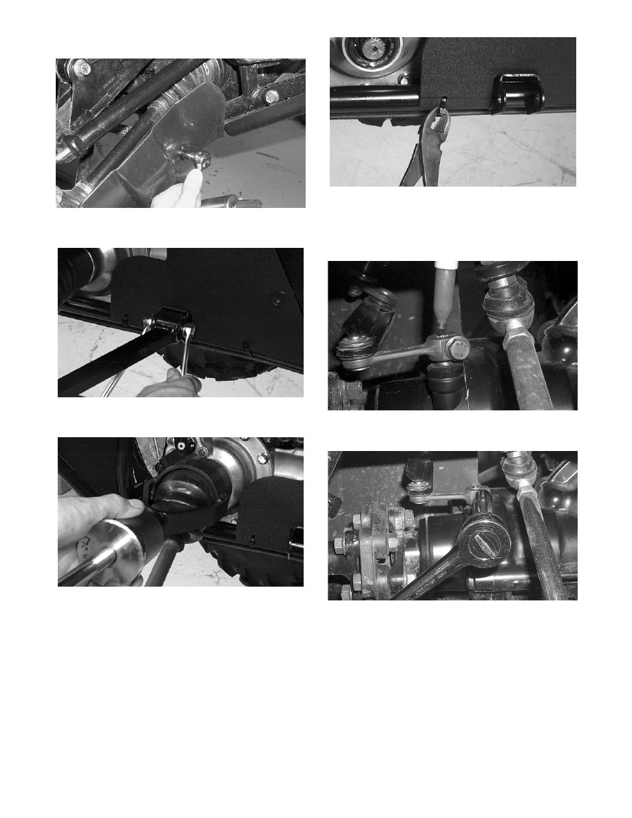
7. Secure the A-arms with cap screws and lock nuts.

Tighten to 4.8 kg-m (35 ft-lb).

AF898D

8. Install the boot guards.

AF934

9. Secure the lower shock eyelets with cap screws

and lock nuts. Tighten to 4.8 kg-m (35 ft-lb).

AF897D

10. Secure the tie rods with the lock nuts. Tighten

securely; then install and spread the cotter pins.

AF896D

AF895D

RepairPro Service Manual

-------------------------------------------------------------------------------------------------------------------------------------------------------------

6-7

6

11. Install the brake calipers. Secure with the cap

screws tightened to 2.8 kg-m (20 ft-lb).

AF894D

12. Install the wheels and tighten to 5.5 kg-m

(40 ft-lb).

AF611D

13. Remove the ATV from the support stand.

Drive Axles

REMOVING REAR DRIVE AXLE 

(Fully Independent Rear Suspension)

1. Secure the ATV on a support stand to elevate the

wheels.

2. Pump up the hand brake; then engage the brake

lever lock.

3. Remove the wheel and rubber wheel cap.

4. Remove the cotter pin securing the hex nut; then

remove the hex nut and washer. Release the

brake lever lock.

AF700D

5. Remove the two brake calipers (right side only).

!

NOTE: Do not allow the brake calipers to hang

from their cable/hose.

6. Slide the hub out of the knuckle and set aside.

7. Remove the cap screw and lock nut securing the

knuckle to the upper A-arm. Discard the lock

nut.

AF936

!

NOTE: Never reuse a lock nut. Once a lock nut

has been removed, it must be replaced with a new
lock nut.

8. While holding the drive axle stationary, pull the

top of the knuckle out and down until it is free of

the drive axle. 

9. Place a drain pan under the ATV to contain any oil

leakage; then using a slide hammer, remove the

drive axle.

! WARNING

Make sure the ATV is solidly supported on the sup-
port stand to avoid injury.

-------------------------------------------------------------------------------------------------------------------------------------------------------------

6-8

AF935

REMOVING FRONT DRIVE AXLE 

(4x4 Models)

1. Secure the ATV on a support stand to elevate the

wheels.

2. Pump up the hand brake; then engage the brake

lever lock.

3. Remove the wheel and rubber wheel cap.

4. Remove the cotter pin securing the hex nut; then

remove the hex nut and washer. Release the

brake lever lock.

AF700D

5. Remove the brake caliper.

!

NOTE: Do not allow the caliper to hang from its

hose.

AF894D

6. Slide the hub w/brake disc out of the steering

knuckle and set aside.

7. Remove the tie rod from the steering knuckle.

AF896D

8. Remove the cap screw and lock nut securing the

lower shock eyelet to the upper A-arm. Discard

the lock nut. 

!

NOTE: Never reuse a lock nut. Once a lock nut

has been removed, it must be replaced with a new
lock nut.

9. Remove the cap screw securing the upper A-arm

ball joint to the steering knuckle; then disengage

the ball joint from the knuckle.

10. While holding the drive axle stationary, pull the

top of the steering knuckle out and down until it is

free of the drive axle.

11. Place a drain pan under the ATV to contain any oil

leakage; then using a slide hammer, remove the

drive axle.

! WARNING

Make sure the ATV is solidly supported on the sup-
port stand to avoid injury.

RepairPro Service Manual

-------------------------------------------------------------------------------------------------------------------------------------------------------------

6-9

6

AF899D

CLEANING AND INSPECTING

!

NOTE: Always clean and inspect the drive axle

components to determine if any service or replace-
ment is necessary.

1. Using a clean towel, wipe away any oil or grease

from the axle components.

AF883D

2. Inspect boots for any tears, cracks, or

deterioration.

!

NOTE: If a boot is damaged in any way, it must

be replaced with a boot kit.

3. Inspect clamps for looseness or damage; replace as

necessary.

DISASSEMBLING

1. Loosen the large clamp and slide it off the boot.

AF884D

2. Wipe away excess grease to access the retaining

ring. Using an awl or circlip pliers, remove the

circlip; then mark the housing to the bearing ring.

AF885D

AF886D

3. Mark the bearing ring to the shaft.

AF887D

4. Using a snap ring pliers, remove the circlip

securing the bearing ring to the shaft.

-------------------------------------------------------------------------------------------------------------------------------------------------------------

6-10

AF888D

5. Note the difference inside each bearing ring end

for assembly purposes; then remove the bearing

ring.

!

NOTE: The end without splines must face

inward.

AF890D

6. Inspect the splines of the shaft, the bearing ring,

and the housing for damage.

!

NOTE: If any damage is apparent to the splines,

the bearing ring, and/or the housing, the drive axle
must be replaced as an assembly.

7. Loosen the small clamp and slide the clamp and

boot off the shaft.

ATV-1048

!

NOTE: At this point if the outer boot is damaged,

continue with step 8.

8. Loosen both outer boot clamps and slide the outer

boot off the shaft. Note the position of the

different-sized clamps for installation purposes.

AF891D

AF892D

9. Apply grease from the kit into the knuckles and

the new outer boot.

!

NOTE: The large grease pack is for the inner

drive axle bearing and boot assembly.

10. Slide the new outer boot onto the shaft with the

new clamps positioned as shown. Note the

different-sized clamps from removal.

!

NOTE: The boot is positioned correctly when the

small end of the boot seats down into the recessed
groove.

11. Secure both outer boot clamps.

! CAUTION

It is important that the clamps are positioned
correctly or they may loosen when in motion.

RepairPro Service Manual

-------------------------------------------------------------------------------------------------------------------------------------------------------------

6-11

6

AF891D

AF892D

ASSEMBLING

1. Install the inner boot with the small clamp making

sure the ends of the clamps are positioned

correctly.

!

NOTE: The boot is positioned correctly when the

small end of the boot seats down into the recessed
groove.

2. Secure the small clamp of the inner boot.

ATV-1048

3. Apply grease from the kit onto the bearing ring

making sure grease is on both the inner and outer

sides; then apply the remainder of the grease into

the housing and boot.

!

NOTE: The large grease pack is for the inner

drive axle bearing and boot assembly.

ATV-1052

4. Install the bearing onto the shaft making sure the

side without splines goes onto the shaft first.

AF890D

5. Secure the bearing ring with the circlip making

sure the sharp side of the circlip faces away from

the boot.

AF888D

! CAUTION

The bearing ring must go onto the shaft with the
side without splines facing toward the small
clamp of the inner boot or severe damage will
result.

-------------------------------------------------------------------------------------------------------------------------------------------------------------

6-12

ATV1073A

6. Making sure the marks made during disassembly

align, slide the housing over the bearing ring; then

install the circlip.

AF885D

7. Slide the boot over the housing and secure the boot

with the clamp.

AF884D

8. Inspect the axle components for correct

positioning of the four clamps. Also, inspect the

boots for being correctly positioned on the shaft.

INSTALLING REAR DRIVE AXLE 

(Fully Independent Rear Suspension)

1. Slide the drive axle into place in the engine.

2. Swing the knuckle up and onto the drive axle; then

place the knuckle into place in the upper A-arm.

Secure the knuckle to the A-arm with a cap screw

and a new lock nut. Tighten to 4.8 kg-m (35 ft-lb).

3. Place the hub into position on the axle followed by

a washer and hex nut. Tighten the hex nut

finger-tight at this time.

4. If the brake calipers were removed, position them

on the knuckle and secure with existing cap

screws. Tighten the mechanical caliper cap screws

to 2.1 kg-m (15 ft-lb). Tighten the hydraulic

caliper cap screws to 2.8 kg-m (20 ft-lb).

5. Pump up the hand brake; then engage the brake

lever lock.

6. Tighten the hex nut (from step 3) to 10.4 kg-m (75

ft-lb).

7. Install the wheel. Tighten to 5.5 kg-m (40 ft-lb). 

8. Remove the ATV from the support stand and

release the brake lever lock.

9. Check the engine/transmission oil level and add

oil as necessary.

INSTALLING FRONT DRIVE AXLE 

(4x4 Models)

1. Position the drive axle in the engine and steering

knuckle; then insert the upper A-arm ball joint into

the steering knuckle. Secure with a cap screw

tightened to 4.8 kg-m (35 ft-lb).

2. Place the brake hose into position on the upper

A-arm; then secure the lower shock eyelet to the

A-arm with a cap screw and a new lock nut.

Tighten to 4.8 kg-m (35 ft-lb).

3. Secure the tie rod to the steering knuckle with a

new lock nut. Tighten securely; then install and

spread a new cotter pin.

4. Slide the hub w/brake disc into position in the

steering knuckle followed by a washer and hex

nut. Tighten finger-tight at this time.

5. Install the brake caliper on the steering knuckle.

Tighten to 2.8 kg-m (20 ft-lb); then pump up the

hand brake and engage the brake lever lock.

6. Tighten the hub hex nut (from step 4) to 10.4 kg-m

(75 ft-lb); then install and spread a new cotter pin.

7. Install the wheel and tighten to 5.5 kg-m (40 ft-lb). 

8. Remove the ATV from the support stand and

release the brake lever lock.

9. Check the front differential oil level and add oil as

necessary.

RepairPro Service Manual

-------------------------------------------------------------------------------------------------------------------------------------------------------------

6-13

6

ACT - Independent

Rear Suspension 

(Including TBX Model)

REMOVING

1. Place the ATV on a support stand (positioned just

in front of and behind the footrest on each side) so

the wheels are off the floor.

2. Remove the rear wheels.

3. Remove the cap screws securing the brake calipers

to the bearing housing; then remove the calipers

and lay aside.

CC783

4. Remove the lower shock absorber cap screws and

hex nuts; then disengage the shock absorbers from

the axle housings.

!

NOTE: The TBX model has a single shock

absorber mounted to the swing arm.

AF772D

5A. Remove the four cap screws and nuts securing the

rear of the swing arm(s) to the axle housing.

5B. For the TBX model, refer to illustration CC868A.

AF697D

CC868A

6A. Maneuver the axle assembly rearward allowing

the propeller shaft to disengage and the final drive

boot to separate from the drive housing.

6B. For the TBX model, remove the three cap screws

securing the rear gear case U-joint to the

driveshaft.

! WARNING

Make sure the ATV is solidly supported on the sup-
port stand to avoid injury.

! CAUTION

Care should be taken not to damage the brake
cable/hose when laying the calipers aside. Do
not allow the calipers to hang from the brake
cable/hose.

! CAUTION

Ensure that the rear gear case is properly
supported BEFORE removing the shock
absorber assembly/assemblies.

-------------------------------------------------------------------------------------------------------------------------------------------------------------

6-14

DISASSEMBLING

1. Remove the cap screws securing the gear case

panel; then remove the panel from the gear case.

CC762

CC763

2. Remove the cap screws securing the axle assembly

to the axle housing; then remove the axle assembly

from the housing. Account for a gasket.

CC764

CC765

3. Remove the snap ring securing the bearing

housing to the axle shaft; then slide the bearing

housing off the shaft.

CC768A

4. Remove the four cap screws securing the hitch to

the gear case; then remove the hitch.

CC769

5. Remove the two cap screws securing the axle

housing to the gear case.

RepairPro Service Manual

-------------------------------------------------------------------------------------------------------------------------------------------------------------

6-15

6

CC770

6. Remove the axle housing from the gear case.

Account for a gasket.

CC771

CLEANING AND INSPECTING

!

NOTE: Whenever a part is worn excessively,

cracked, or damaged in any way, replacement is
necessary.

1. Clean all external components with parts-cleaning

solvent.

2. Inspect the case for leaks or damage.

3. Inspect splines for wear.

4. Inspect the seal for damage.

5. Inspect housing mounting bosses for wear or

elongated holes.

6. Inspect the frame welds for cracking or bending.

7. Inspect the rear drive and plug threads for

stripping or damage.

8. Inspect the axle bearings. Rotate the bearings by

hand, and if any roughness or binding is noted,

replace the bearings.

ASSEMBLING

1. Grease the splines of the axle housing.

AF705D

2. Make sure the rear gear case/axle housing seal is

properly positioned; then secure the axle housing

to the rear gear case with two cap screws. Tighten

to 4.8 kg-m (35 ft-lb).

!

NOTE: If a new rear gear case is being installed,

tighten the cap screws to 5.5 kg-m (40 ft-lb).

CC770

3. Secure the axle housing to the rear gear case with

four cap screws. Tighten to 4.8 kg-m (35 ft-lb).

!

NOTE: If a new rear gear case is being installed,

tighten the cap screws to 5.5 kg-m (40 ft-lb).

CC769

4. Lightly grease the bearing housing seal; then slide

the bearing housing onto the axle shaft. Secure

with the snap ring.

-------------------------------------------------------------------------------------------------------------------------------------------------------------

6-16

CC768

5. Place the axle gasket on the axle housing. Rotate

the axle shaft slightly to ensure proper engagement

with the gear case splines.

6. Rotate the bearing housing until the brake caliper

mounting holes are on the top side; then secure the

axle retainer assembly/axle assembly to the axle

housing with four cap screws. Tighten to 5.5 kg-m

(40 ft-lb).

CC764

INSTALLING

1A. Maneuver the axle assembly forward making sure

propeller shaft splines engage properly and the

final drive boot is positioned over the drive

housing.

1B. For the TBX model, maneuver the axle assembly

forward and secure the rear gear case U-joint to

the driveshaft with cap screws coated with red

Loctite #271. Tighten to 5.5 kg-m (40 ft-lb).

2A. Place the rear of the swing arm(s) into position on

the axle housings and case; then secure with four

cap screws and hex nuts. Tighten to 4.8 kg-m (35

ft-lb).

AF697D

2B. For the TBX model, refer to illustration CC867A.

CC867A

3. Place the shock absorber into the frame mounts

and secure using the cap screws and hex nuts

tightened to 4.8 kg-m (35 ft-lb).

4. Place the brake calipers into position on the axle

retainer assembly; then secure with the cap

screws. Tighten the mechanical caliper to 2.1

kg-m (15 ft-lb) and the hydraulic caliper to 2.8

kg-m (20 ft-lb).

CC783

! CAUTION

Do not tighten nuts beyond the 4.8 kg-m (35 ft-lb)
specification or the shock eyelet or mount WILL
be damaged.

RepairPro Service Manual

-------------------------------------------------------------------------------------------------------------------------------------------------------------

6-17

6

5. Place the gear case panel into position and secure

with the three cap screws. Tighten securely.

CC762

CC763

6. Install the wheels and tighten to 5.5 kg-m

(40 ft-lb).

7. Remove the ATV from the support stand.

!

NOTE: Check all fasteners for tightness and

check the brakes for proper operation before test
riding.

Rear Gear Case

(400 Models)

The rear gear case is a non-serviceable component. If

it is damaged or worn, it must be replaced.

REMOVING

1. Remove the left-side rear A-arms (see Rear

A-Arms in Section 7).

2. Remove both of the rear drive axles (see Drive

Axles in this section).

3. Remove the three cap screws and lock nuts

securing the engine output shaft to the rear gear

case input flange.

AF959

4. Remove the two cap screws and lock nuts securing

the rear gear case to the frame; then remove the

gear case through the left side.

AF960A

INSTALLING

1. Slide the gear case into position through the left

side of the frame; then secure it to the frame with

cap screws and lock nuts. Tighten to 4.8 kg-m (35

ft-lb).

!

NOTE: If a new rear gear case is being installed,

tighten the cap screws to 5.5 kg-m (40 ft-lb).

2. Secure the engine output shaft to the rear gear case

input flange with three cap screws (coated with red

Loctite #271) and lock nuts. Tighten to 4.8 kg-m

(35 ft-lb).

3. Install the rear drive axles (see Drive Axles in this

section).

4. Install the left-side rear A-arms (see Rear A-Arms

in Section 7).

! CAUTION

Care should be taken not to damage or kink the
brake cable/hose when installing the calipers.

-------------------------------------------------------------------------------------------------------------------------------------------------------------

6-18

Hub

REMOVING

1. Secure the ATV on a support stand to elevate the

wheel; then remove the wheel.

2. Remove the wheel cap from the hub; then remove

the cotter pin from the nut.

!

NOTE: During assembly, new cotter pins should

be installed.

AF700D

3. Remove the nut securing the hub. Account for a

washer and a hub seal.

AF701D

4. Remove the brake caliper.

AF615D

5. Remove the hub assembly.

6. Remove the four cap screws securing the brake

disc.

CLEANING AND INSPECTING

!

NOTE: Whenever a part is worn excessively,

cracked, or damaged in any way, replacement is
necessary.

1. Clean all hub components.

2. Inspect all threads for stripping or damage.

3. Inspect the brake disc for cracks or warping.

4. Inspect the sealing area of the hub for pits.

5. Inspect the hub splines for signs of wear.

6. Inspect the hub for cracks.

INSTALLING

1. Secure the brake disc to the hub with the four cap

screws coated with blue Loctite #243. Tighten to

2.1 kg-m (15 ft-lb).

2. Apply grease to hub sealing area and on the

splines.

AF736D

3. Install the hub assembly onto the splines of the

shaft.

! WARNING

Make sure the ATV is solidly supported on the sup-
port stand to avoid injury.

RepairPro Service Manual

-------------------------------------------------------------------------------------------------------------------------------------------------------------

6-19

6

AF702D

4. Insert the hub seal onto the shaft; then position it

into the hub.

AF701D

5. Place the washer onto the shaft; then secure the

hub assembly with the nut. Tighten only until

snug.

6. Secure the brake caliper to the knuckle with the

two cap screws. Tighten the mechanical caliper to

2.1 kg-m (15 ft-lb). Tighten the hydraulic caliper

to 2.8 kg-m (20 ft-lb).

AF615D

7. Secure the hub nut to the shaft/axle. Tighten to

10.4 kg-m (75 ft-lb).

8. Install a new cotter pin and spread the pin to

secure the nut.

AF700D

9. Install the wheel cap.

10. Install the wheel and tighten to 5.5 kg-m (40 ft-lb).

AF611D

11. Remove the ATV from the support stand.

Hydraulic

Brake Caliper

!

NOTE: The brake caliper is a non-serviceable

component; it must be replaced as an assembly.

REMOVING/DISASSEMBLING

1. Secure the ATV on a support stand to elevate the

wheel; then remove the wheel.

2. Drain the brake fluid from the entire hydraulic

system (master cylinder, hoses, and caliper).

! WARNING

Make sure the ATV is solidly supported on the sup-
port stand to avoid injury.

-------------------------------------------------------------------------------------------------------------------------------------------------------------


Content      ..     18      19      20      21     ..