ATV Arctic Cat 2002. Service Manual - part 18
 

  Index      Manuals     ATV Arctic Cat 2002. Service Manual


Search            copyright infringement  


Content      ..     16      17      18      19     ..


ATV Arctic Cat 2002. Service Manual - part 18


5-3

5

Battery

1. Remove the battery from the ATV.

2. Remove the vent plugs; then fill the battery with

electrolyte to the UPPER level indicated on the

battery.

!

NOTE: Electrolyte should be at room tempera-

ture before filling. Do not use water or any other
liquid to activate a battery.

3. Allow the battery to stand for 15-30 minutes after

filling. Electrolyte level may fall during this time.

Refill with electrolyte to UPPER level line.

4. Trickle-charge the battery at 1.4 amps for 8-10

hours.

5. After charging, check electrolyte level and fill

with DISTILLED WATER as necessary; then

install the vent plugs. Wash off acid spillage with

water and dry the battery.

6. Place the battery into position in the ATV and

secure; then connect the vent hose to the battery.

7. Connect cables to the proper terminals: positive

cable to the positive terminal (+) and negative

cable to the negative terminal (-). Connect the

negative cable last.

8. Check the vent tube to make sure it is not pinched

or obstructed in any way and that it is properly

routed down through the frame.

RPM Limiter

The ATV has an RPM limiter system to limit the

engine RPM. One way to eliminate the activation of

the RPM limiter is to utilize the throttle limiter screw

at the throttle lever.

!

NOTE: The ATV is equipped with a CDI unit that

retards ignition timing when maximum RPM is
approached. When the RPM limiter is activated, it
could be misinterpreted as a high-speed misfire.

1. Ensure that the throttle cable is adjusted correctly

at 3-6 mm (1/8-1/4 in.) free-play at the lever.

500

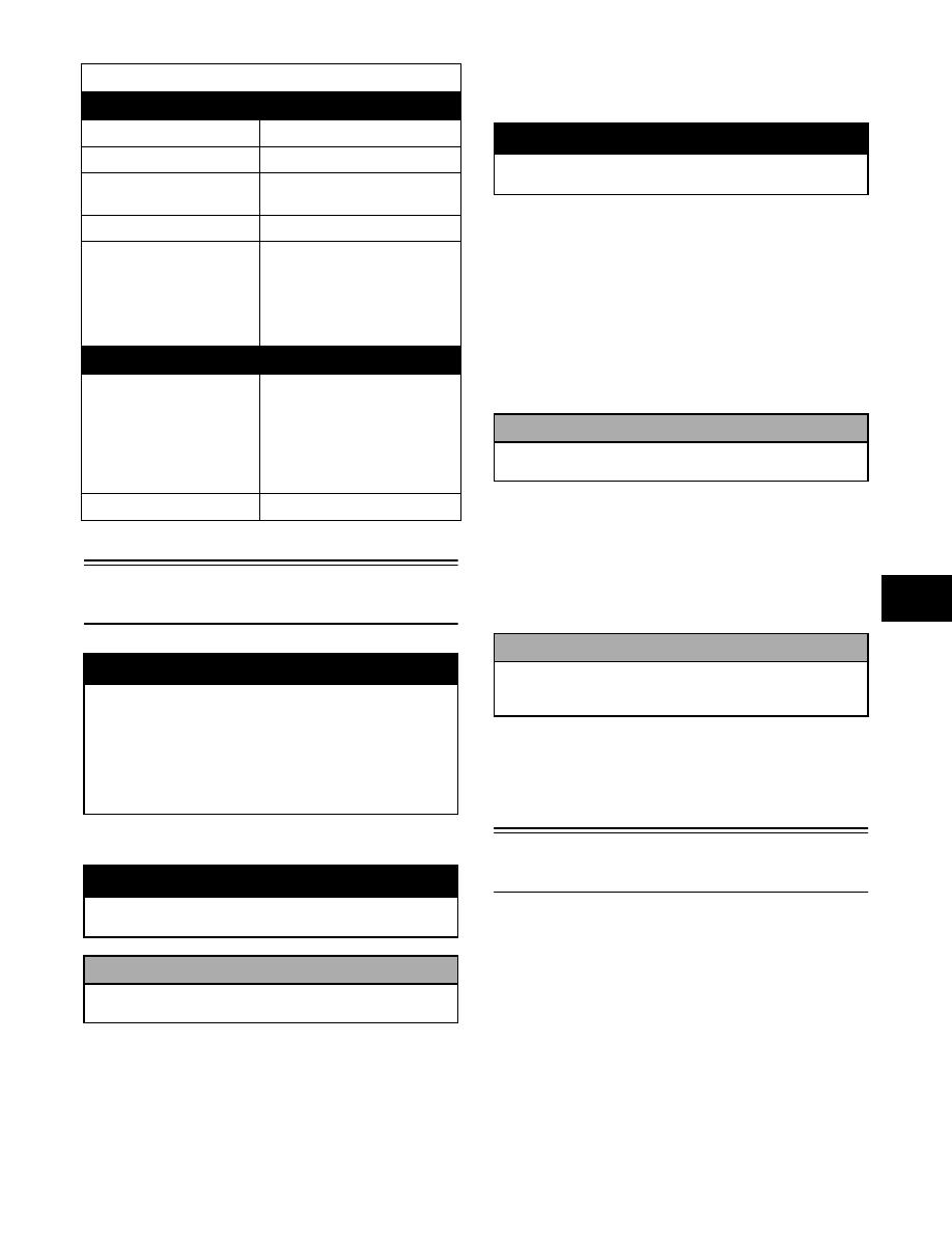
IGNITION

Ignition Timing

10° BTDC @ 1500 RPM

Spark Plug Type

NGK CR6E

Spark Plug Gap

0.7-0.8 mm
(0.028-0.032 in.)

Spark Plug Cap

8000-12,000 ohms

Ignition Coil Resistance

(primary)

(secondary)

0.1-1.0 ohm 

(terminal to ground)

4500-10,000 ohms

(high tension - plug cap 
removed - to ground)

MAGNETO

Magneto Coil Resistance

(trigger)

                (source/charge)

(charging)

150-300 ohms

(green to blue)

0.05-1.0 ohm

(yellow to white)

0.1-1.0 ohm

(black to black)

Magneto Output (approx) 325W @ 5000 RPM

! WARNING

Anytime service is performed on a battery, the fol-
lowing must be observed: keep sparks, open flame,
cigarettes, or any other flame away. Always wear
safety glasses. Protect skin and clothing when han-
dling a battery. When servicing battery in enclosed
space, keep the area well-ventilated. Make sure
venting tube of battery is always open once battery
is filled with electrolyte.

! WARNING

Remove the negative cable first; then remove the
positive cable.

! CAUTION

Do not charge the battery while it is in the ATV
with the battery terminals connected.

! WARNING

Electrolyte is a sulfuric acid solution. Avoid spillage
and contact with skin, eyes, and clothing.

! CAUTION

Before installing the battery, make sure the
ignition switch is in the OFF position.

! CAUTION

Connecting cables in reverse (positive to
negative and negative to positive) can cause
serious damage to the electrical system.

RepairPro Service Manual

-------------------------------------------------------------------------------------------------------------------------------------------------------------

5-4

ATV-0047

2. Loosen the jam nut of the limiter screw and rotate

the screw clockwise until RPM is limited to under

9000 RPM (250/300) or under 8300 RPM

(375/400/500); then tighten the jam nut.

ATV-0053

Testing Electrical 

Components

All of the electrical tests should be made using the

Fluke Model 73 Multimeter (p/n 0644-191). If any

other type of meter is used, readings may vary due to

internal circuitry. When troubleshooting a specific

component, always verify first that the fuse(s) are

good, that the bulb(s) are good, that the connections

are clean and tight, that the battery is fully charged,

and that all appropriate switches are activated.

!

NOTE: For absolute accuracy, all tests should be

made at room temperature of 68° F.

732-410D

Accessory 

Receptacle/Connector 

(375/400/500)

!

NOTE: This test procedure is for either the

receptacle or the connector.

VOLTAGE

1. Set the meter selector to the D.C. Voltage position.

2. Connect the red tester lead to the red/white wire or

the positive connector; then connect the black

tester lead to ground.

AR606D

3. The meter must show battery voltage.

!

NOTE: If the meter shows no battery voltage,

troubleshoot the battery, fuse, receptacle, connec-
tor, or the main wiring harness.

-------------------------------------------------------------------------------------------------------------------------------------------------------------

5-5

5

Brakelight Switch

(Foot)

The switch connector is the two-prong connector on

the right side of the engine directly above the brake

cable adjuster.

!

NOTE: The ignition switch must be in the ON

position.

VOLTAGE

(Wiring Harness Side)

1. Set the meter selector to the D.C. Voltage position.

2. Connect the red tester to the orange wire; then

connect the black tester lead to ground.

AR627D

3. The meter must show battery voltage.

!

NOTE: If the meter shows no battery voltage,

troubleshoot the battery, fuse, switch, or the main
wiring harness.

!

NOTE: If the meter shows battery voltage, the

main wiring harness is good; proceed to test the
switch/component, the connector, and the switch
wiring harness for resistance.

RESISTANCE

(Brakelight Switch Connector)

1. Set the meter selector to the OHMS position.

2. Connect the red tester lead to one black wire; then

connect the black tester lead to the other black

wire.

AR626D

3. When the brake pedal is depressed, the meter must

show less than 1 ohm.

!

NOTE: If the meter shows more than 1 ohm of

r e s i s t a n c e ,   t r o u b l e s h o o t   o r   r e p l a c e   t h e
switch/component, the connector, or the switch
wiring harness.

Brakelight Switch 

(Handlebar Control)

The switch connector is the two-prong black connector

in front of the steering post. To access the connector,

the front rack and front fenders must be removed (see

Section 8).

!

NOTE: The ignition switch must be in the ON

position.

VOLTAGE

(Wiring Harness Connector)

1. Set the meter selector to the D.C. Voltage position.

2. Connect the red tester lead to the orange wire; then

connect the black tester lead to ground.

AR622D

3. The meter must show battery voltage.

!

NOTE: If the meter shows no battery voltage,

troubleshoot the battery, fuse, switch, or the main
wiring harness.

! CAUTION

Always disconnect the battery when performing
resistance tests to avoid damaging the
multimeter.

RepairPro Service Manual

-------------------------------------------------------------------------------------------------------------------------------------------------------------

5-6

!

NOTE: If the meter shows battery voltage, the

main wiring harness is good; proceed to test the
switch/component, the connector, and the switch
wiring harness for resistance.

RESISTANCE

(Brakelight Switch Connector)

!

NOTE: The brake lever must be compressed for

this test. Also, the ignition switch must be in the
OFF position.

1. Set the meter selector to the OHMS position.

2. Connect the red tester lead to one black wire; then

connect the black tester lead to the other black

wire.

AR621D

3. When the lever is compressed, the meter must

show less than 1 ohm.

!

NOTE: If the meter shows more than 1 ohm of

r e s i s t a n c e ,   t r o u b l e s h o o t   o r   r e p l a c e   t h e
switch/component, the connector, or the switch
wiring harness.

Oil Temperature Switch 

(250/300/375)

1. Connect the meter leads (selector in the OHMS

position) to the temperature switch contacts.

2. Suspend the temperature switch and a

thermometer in a container of oil; then heat the oil.

!

NOTE: Neither the temperature switch nor the

thermometer should be allowed to touch the bot-
tom of the container or inaccurate readings will
occur. Use wire holders to suspend switch and
thermometer.

733-554B

3. When the oil temperature reaches 160° C (320° F),

the meter should read a closed circuit.

4. Allow the oil to cool, and when the temperature is

at (or just before) a temperature of 140° C (284°

F), the meter should read an open circuit.

5. If the readings are not as indicated, the

temperature switch must be replaced.

6. Apply teflon tape to the threads of the switch; then

install the switch and tighten securely.

7. Connect the temperature switch leads.

Fan Motor

(375/400/500)

To access the connector (located directly behind the

fan), the front rack and front fenders must be removed

(see Section 8).

!

NOTE: The ignition switch must be in the ON

position.

VOLTAGE 

(Main Harness Connector to Fan 

Motor)

1. Set the meter selector to the D.C. Voltage position.

2. Connect the red tester lead to the black/red wire

(the black 2-prong at the fan motor); then connect

the black tester lead to ground.

3. The meter must show battery voltage.

!

NOTE: If the meter shows no battery voltage,

troubleshoot the battery, fuse, motor, or the main
wiring harness.

!

NOTE: If the meter shows battery voltage, the

main wiring harness is good. The connector
should be checked for resistance.

! CAUTION

Always disconnect the battery when performing
resistance tests to avoid damaging the
multimeter.

-------------------------------------------------------------------------------------------------------------------------------------------------------------

5-7

5

RESISTANCE

(Fan Motor Connector)

1. Set the meter selector to the OHMS position.

2. Connect the red tester lead to the blue wire; then

connect the black tester lead to the black wire.

AR645D

3. The meter must show less than 1 ohm.

!

NOTE: If the meter shows more than 1 ohm of

r e s i s t a n c e ,   t r o u b l e s h o o t   o r   r e p l a c e   t h e
switch/component, the connector, or the switch
wiring harness.

!

NOTE: To determine if the fan motor is good,

connect the blue wire from the fan connector to a
12 volt D.C. power supply; then connect the black
wire from the fan connector to ground. The fan
should operate.

Fuse Block

The main (30 Amp) fuse is located on the frame near

the right rear tire and protected by a snap-on cover.

!

NOTE: To remove the fuse, compress the lock-

ing tabs on either side of the fuse case and lift out.

The remaining fuses are located under the center cover

in the front fender assembly (on the 250/300) or under

th e   se a t  i n  th e  ba tt e ry   c om pa rt m e n t  ( on   t he

375/400/500). If there is any type of electrical system

failure, always check the fuses first.

!

NOTE: If all voltage is lost at the fuse block,

check the condition of the fuses.

!

NOTE: The ignition switch must be in the

LIGHTS position.

1. Remove all fuses from the fuse box.

2. Set the meter selector to the D.C. Voltage position.

3. Connect the black tester lead to ground.

4. Using the red tester lead, contact each end of the

fuse holder connector terminals individually.

CH095D

5. The meter must show battery voltage from one

side of the connector terminal ends.

!

NOTE: Battery voltage will be indicated from

only one side of the fuse holder connector termi-
nal; the other side will show an open circuit.

!

NOTE: When testing the HI fuse holder, the

headlight dimmer switch must be in the HI posi-
tion; when testing the LO fuse holder, the head-
light dimmer switch must be in the LO position.

!

NOTE: If the meter shows no battery voltage,

troubleshoot the battery, switches, fuse block, or
the main wiring harness.

Fuses

1. Set the meter selector to the OHMS position.

2. Connect the red tester lead to one spade end of the

fuse; then connect the black tester lead to the other

spade end.

! CAUTION

Always disconnect the battery when performing
resistance tests to avoid damaging the
multimeter.

! CAUTION

Care should be taken to keep clear of the fan
blades.

! CAUTION

Always disconnect the battery when performing
resistance tests to avoid damaging the
multimeter.

250/300

RepairPro Service Manual

-------------------------------------------------------------------------------------------------------------------------------------------------------------

5-8

AR610D

3. The meter must show less than 1 ohm resistance.

If the meter reads open, replace the fuse.

!

NOTE: Make sure the fuses are returned to their

proper position according to amperage. Refer to
the fuse block cover for fuse placement.

Gear Position Lights

(Manual Transmission)

The Gear Position Lights connector being tested is the

black six-terminal connector (5 female and 1 male)

coming from the gear position light wiring harness.

ATV-GPL

To access the gear position light connector for testing

purposes, use the following procedure.

1. Remove the three machine screws and key cover

securing the instrument pod.

2. Remove the light bar from the instrument pod;

then cut the cable tie securing the instrument pod

wiring to the steering post.

3. Push the instrument pod wiring with light bar

downward to access the gear position light

connector; then disconnect the connector from the

main wiring harness.

!

NOTE: For testing purposes, the Indicator Lights

connector must also be disconnected to access
the power source terminal.

ATV-ILA

!

NOTE: For these tests, a 12-volt power supply

“jumper” should be used to supply power.

FIRST GEAR

1. Connect the jumper positive wire to the power

source terminal on the indicator light connector.

2. Connect the jumper ground wire to the first gear

terminal on the gear position light connector.

3. The first gear position indicator light should

illuminate.

SECOND GEAR

1. Connect the jumper positive wire to the power

source terminal on the indicator light connector.

2. Connect the jumper ground wire to the second

gear terminal on the gear position light connector.

3. The second gear position indicator light should

illuminate.

THIRD GEAR

1. Connect the jumper positive wire to the power

source terminal on the indicator light connector.

2. Connect the jumper ground wire to the third gear

terminal on the gear position light connector.

3. The third gear position indicator light should

illuminate.

FOURTH GEAR

1. Connect the jumper positive wire to the power

source terminal on the indicator light connector.

2. Connect the jumper ground wire to the fourth gear

terminal on the gear position light connector.

5th

4th

DEAD

1st

2nd

3rd

GEAR POSITION LIGHTS

= Male Terminal

= Female Terminal

-------------------------------------------------------------------------------------------------------------------------------------------------------------

5-9

5

3. The fourth gear position indicator light should

illuminate.

FIFTH GEAR

1. Connect the jumper positive wire to the power

source terminal on the indicator light connector.

2. Connect the jumper ground wire to the fifth gear

terminal on the gear position light connector.

3. The fifth gear position indicator light should

illuminate.

!

NOTE: If the gear position indicator lights work

properly, the gear position wiring harness, con-
nectors, and bulbs are good. Troubleshoot the
gear position switch.

After testing procedures are completed, use the follow-

ing procedure.

1. Connect both light connectors to the main wiring

harness.

2. Pull the instrument pod wiring with light bar

upward and install the light bar into the instrument

pod.

3. Secure the instrument pod with existing hardware;

then secure the instrument pod wiring to the

steering post using a cable tie.

Gear Position Switch

(Manual Transmission)

!

NOTE: The ignition switch must be in the OFF

position. Also, the tests should be made at the
white connector directly behind the reverse lever.
Test the lower end of the connector (coming from
the switch).

NEUTRAL POSITION

!

NOTE: For these tests, the meter selector should

be set to the OHMS position.

1. Connect the red tester lead to the red/black wire;

then connect the black tester lead to ground.

2. With the shifter in the neutral position, the meter

must show less than 1 ohm.

FIRST GEAR

1. Connect the red tester lead to the white/yellow

wire; then connect the black tester lead to ground.

2. With the shifter in the first gear position, the meter

must show less than 1 ohm.

SECOND GEAR

1. Connect the red tester lead to the green/red wire;

then connect the black tester lead to ground.

2. With the shifter in the second gear position, the

meter must show less than 1 ohm.

THIRD GEAR

1. Connect the red tester lead to the brown/red wire;

then connect the black tester lead to ground.

2. With the shifter in the third gear position, the

meter must show less than 1 ohm.

FOURTH GEAR

1. Connect the red tester lead to the yellow/blue wire;

then connect the black tester lead to ground.

2. With the shifter in the fourth gear position, the

meter must show less than 1 ohm.

FIFTH GEAR

1. Connect the red tester lead to the green/blue wire;

then connect the black tester lead to ground.

2. With the shifter in the fifth gear position, the meter

must show less than 1 ohm.

!

NOTE: If any of the above tests show more than

1 ohm, the switch/harness and/or the connectors
must be replaced.

Ignition Coil

On the 250/300, the ignition coil is attached to the

upper frame behind the right-hand side panel. To

access the coil, the seat and right-hand side panel must

be removed (see Section 8).

On the 375/400/500, the ignition coil is on top of the

engine. To access the coil, the seat and gas tank (see

Section 4) must be removed.

VOLTAGE (Primary Side)

!

NOTE: The ignition switch must be in the ON

position; the emergency stop switch must be in
the RUN position. Also, the white/blue wire must
be disconnected from the coil.

1. Set the meter selector to the D.C. Voltage position.

! CAUTION

Always disconnect the battery when performing
resistance tests to avoid damaging the
multimeter.

RepairPro Service Manual

-------------------------------------------------------------------------------------------------------------------------------------------------------------

5-10

2. Connect the black tester lead to the white/blue

wire; then connect the red tester lead to ground.

3. The meter must show 31V ± 20%.

4. With the tester leads connected, depress the starter

button.

5. The meter must show 130V ± 20%.

!

NOTE: If the voltage is not as specified in one or

both of the above tests, inspect the main wiring
harness, connectors, source/charge coil, magneto
rotor and magnets, magneto rotor key, or the CDI
unit.

RESISTANCE

!

NOTE: For these tests, the meter selector should

be set to the OHMS position.

Primary Winding

1. Connect the red tester lead to the terminal (with

the wire removed); then connect the black tester

lead to ground.

CH097D

AR615D

2. The meter must show 0.1- 0.5 ohm (250/300),

0.05-0.5 ohm (375), or 0.1-1.0 ohm (400/500).

Secondary Winding

1. Connect the red tester lead to the high tension lead

(plug cap removed); then connect the black tester

lead to ground.

CH098D

AR601D

2. The meter must show 5200-7800 ohms (250/300),

4000-9000 ohms (375), or 4500-10,000 ohms

(400/500).

!

NOTE: If the meter does not show as specified,

replace ignition coil.

Spark Plug Cap

1. Connect the red tester lead to one end of the cap;

then connect the black tester lead to the other end

of the cap.

AR603D

2. The meter must show 8000-12,000 ohms.

! CAUTION

Always disconnect the battery when performing
resistance tests to avoid damaging the
multimeter.

250/300

375/400/500

250/300

375/400/500

-------------------------------------------------------------------------------------------------------------------------------------------------------------

5-11

5

!

NOTE: If the meter does not read as specified,

replace the spark plug cap.

Indicator Lights

The Indicator Lights connector being tested is the

black six-terminal connector (1 female and 5 male)

coming from the indicator light wiring harness.

ATV-IL

To access the indicator light connector for testing pur-

poses, use the following procedure.

1. Remove the three machine screws and key cover

securing the instrument pod.

2. Remove the light bar from the instrument pod;

then cut the cable tie securing the instrument pod

wiring to the steering post.

3. Push the instrument pod wiring with light bar

downward to access the indicator light connector;

then disconnect the connector from the main

wiring harness.

!

NOTE: For these tests, a 12-volt power supply

“jumper” should be used to supply power.

TEMPERATURE LIGHT

1. Connect the jumper positive wire to the power

source terminal on the indicator light connector.

2. Connect the jumper ground wire to the

temperature terminal on the indicator light

connector.

3. The temperature warning indicator light should

illuminate.

NEUTRAL POSITION LIGHT

1. Connect the jumper positive wire to the power

source terminal on the indicator light connector.

2. Connect the jumper ground wire to the neutral

terminal on the indicator light connector.

3. The neutral position indicator light should

illuminate.

REVERSE POSITION LIGHT

1. Connect the jumper positive wire to the power

source terminal on the indicator light connector.

2. Connect the jumper ground wire to the reverse

terminal on the indicator light connector.

3. The reverse position indicator light should

illuminate.

HI BEAM LIGHT

1. Connect the jumper positive wire to the high beam

terminal on the indicator light connector.

2. Connect the jumper ground wire to the female

terminal on the indicator light connector.

3. The HI beam indicator light should illuminate.

!

NOTE: If a light fails to illuminate in any one of

the indicator light tests, the connector, wiring har-
ness, or a bulb must be replaced.

After testing procedures are completed, use the follow-

ing procedure.

1. Connect the indicator light connector to the main

wiring harness.

2. Pull the instrument pod wiring with light bar

upward and install the light bar into the instrument

pod.

3. Secure the instrument pod with existing hardware;

then secure the instrument pod wiring to the

steering post using a cable tie.

HI BEAM INDICATOR VOLTAGE

!

NOTE: The ignition switch must be in the

LIGHTS position. Also, the dimmer switch must be
in the HI position, and the test must be performed
on the lower side of the connector.

1. Set the meter selector to the D.C. Voltage position.

2. Connect the red tester lead to the yellow wire; then

connect the black tester lead to the black wire.

3. The meter must show battery voltage.

!

NOTE: The meter may show less than 12 volts

due to the draw from the headlights.

OIL TEMPERATURE LIGHT VOLTAGE 

(250/300/375)

!

NOTE: The ignition switch must be in the ON

position, and the test must be performed on the
lower side of the switch.

High Beam

Temperature

Neutral

Power Source

Reverse

INDICATOR LIGHTS

Ground

= Male Terminal
= Female Terminal

RepairPro Service Manual

-------------------------------------------------------------------------------------------------------------------------------------------------------------

5-12

1. Set the meter selector to the D.C. Voltage position.

2. Disconnect the white oil temperature switch

connector from the switch (on the top right side of

the engine) and ground the violet wire to the

engine. The temperature light should illuminate.

3. Connect the red tester lead to the violet wire (main

harness side); then connect the black tester lead to

a ground.

4. The meter must show battery voltage.

WATER TEMPERATURE LIGHT 

VOLTAGE (400/500)

!

NOTE: The ignition switch must be in the ON

position, and the test must be performed on the
lower side of the switch.

1. Set the meter selector to the D.C. Voltage position.

2. Remove the violet water temperature switch wire

connector from the switch (on the left side of the

engine below the water hose) and ground it to the

engine.

3. Connect the red tester lead to the red/black wire

from the fan temperature switch; then connect the

black tester lead to the violet wire from the water

temperature switch.

4. The meter must show battery voltage.

NEUTRAL POSITION VOLTAGE

!

NOTE: The ignition switch must be in the ON

position. Also, the shifter must be in the NEUTRAL
position, and the test must be performed on the
lower side of the connection.

1. Set the meter selector to the D.C. Voltage position.

2. Connect the red tester lead to the red/black wire;

then connect the black tester lead to the blue/white

wire.

3. The meter must show battery voltage.

REVERSE POSITION VOLTAGE

!

NOTE: The ignition switch must be in the ON

position. Also, the reverse lever must be in the
REVERSE position, and the test must be per-
formed on the lower side of the connector.

1. Set the meter selector to the D.C. Voltage position.

2. Connect the red tester lead to the red/black wire;

then connect the black tester lead to the blue wire.

3. The meter must show battery voltage.

!

NOTE: If the meter fails to show voltage in any of

the above tests, the connector, fuse, switch, or
wiring harness must be replaced.

Ignition Switch

The connector is the green one beneath the console. To

access the connector, the speedometer and instrument

pod must be removed.

VOLTAGE

!

NOTE: Perform this test on the lower side of the

connector.

1. Set the meter selector to the D.C. Voltage position.

2. Connect the red meter lead to the red wire; then

connect the black meter lead to ground.

3. Meter must show battery voltage.

!

NOTE: If the meter shows no battery voltage,

troubleshoot the battery or the main wiring har-
ness.

RESISTANCE

!

NOTE: Perform this test on the upper side of the

connector.

1. Turn the ignition switch to the ON position.

2. Set the meter selector to the OHMS position.

3. Connect the red tester lead to the red wire; then

connect the black tester lead to the orange wire.

4. The meter must show less than 1 ohm.

5. Turn the ignition switch to the LIGHTS position.

6. Connect the red tester lead to the red wire; then

connect the black tester lead to the orange wire.

7. The meter must show less than 1 ohm.

8. Connect the red tester lead to the red wire; then

connect the black tester lead to the gray wire.

9. The meter must show less than 1 ohm.

10. With the switch in the OFF position, connect the

red tester lead to the red wire and the black tester

lead to each of the remaining wires (orange and

gray). The meter must show an open circuit on

both wires.

!

NOTE: If the meter shows more than 1 ohm of

resistance, troubleshoot or replace the switch/com-
ponent, the connector, or the switch wiring harness.

! CAUTION

Always disconnect the battery when performing
resistance tests to avoid damaging the
multimeter.

-------------------------------------------------------------------------------------------------------------------------------------------------------------

5-13

5

Handlebar Control 

Switches

The connector is the yellow one in front of the steering

post. To access the connector, the front rack and front

fenders must be removed (see Section 8).

!

NOTE: These tests should be made on the top

side of the connector.

RESISTANCE (HI Beam)

1. Set the meter selector to the OHMS position.

2. Connect the red tester lead to the yellow wire; then

connect the black tester lead to the gray wire.

3. With the dimmer switch in the HI position, the

meter must show less than 1 ohm.

!

NOTE: If the meter shows more than 1 ohm of

r e s i s t a n c e ,   t r o u b l e s h o o t   o r   r e p l a c e   t h e
switch/component, the connector, or the switch
wiring harness.

RESISTANCE (LO Beam)

1. Connect the red tester lead to the white wire; then

connect the black tester lead to the gray wire.

2. With the dimmer switch in the LO position, the

meter must show an open circuit.

!

NOTE: If the meter reads resistance, trouble-

shoot or replace the switch/component, the con-
nector, or the switch wiring harness.

RESISTANCE (Starter Button)

1. Set the meter selector to the Diode position.

2. Connect the red tester lead to the orange/white

wire; then connect the black tester lead to the

yellow/green wire.

3. With the starter button depressed, the meter must

show 0.5 - 0.7 ohm.

4. With the starter button released, the meter must

show an open circuit.

5. Connect the red tester lead to the yellow/green

wire; then connect the black tester lead to the

orange/white wire.

6. With the starter button depressed, the meter must

show an open circuit.

!

NOTE: If the meter does not show as specified,

replace the switch/component, connector, or
switch harness.

RESISTANCE (Emergency Stop)

1. Set the meter selector to the OHMS position.

2. Connect the red tester lead to the orange wire; then

connect the black tester lead to the orange/white

wire.

3. With the switch in the OFF position, the meter

must show an open circuit.

4. With the switch in the RUN position, the meter

must show less than 1 ohm.

!

NOTE: If the meter shows more than 1 ohm of

r e s i s t a n c e ,   t r o u b l e s h o o t   o r   r e p l a c e   t h e
switch/component, the connector, or the switch
wiring harness.

RESISTANCE (Reverse Override)

The connector is the four-prong white one in front of

the steering post. To access the connector, the front

rack and front fenders must be removed (see Section

8).

1. Set the meter selector to the OHMS position.

2. Connect the red tester lead to one red/yellow wire

(red/white wire on some models); then connect the

black tester wire to the other red/yellow wire (red

wire on some models). The meter must show less

than 1 ohm.

3. Depress and hold the reverse override button. The

meter must show an open circuit.

4. Connect the red tester lead to the blue wire

(blue/white wire on some models); then connect

the black meter lead to the black wire (blue wire

on some models). The meter must show an open

circuit.

5. Depress and hold the reverse override button. The

meter must show less than 1 ohm.

!

NOTE: If the meter does not show as specified,

replace the switch/component, connector, or
switch harness.

! CAUTION

Always disconnect the battery when performing
resistance tests to avoid damaging the
multimeter.

RepairPro Service Manual

-------------------------------------------------------------------------------------------------------------------------------------------------------------

5-14

Magneto Assembly

VOLTAGE (Charging Coils - Output)

1. Set the meter selector to the D.C. Voltage position.

2. Connect the red tester lead to the positive battery

post; then connect the black tester lead to the

negative battery post.

3. With the engine running at a constant 5000 RPM

(with the headlights on), the meter must show

14-15.5 D.C. volts.

!

NOTE: If voltage is lower than specified, test

charging coils - no load.

VOLTAGE 

(Charging Coils - No Load)

The connector is the black and white one on the right

side of the engine just above the brake cable adjuster.

!

NOTE: Test the connector that comes from the

engine.

1. Set the meter selector to the A.C. Voltage position.

2. Test between the three yellow wires (250/300) for

a total of three tests or the three black wires

(375/400/500) for a total of three tests.

AR630D

3. With the engine running at a constant 5000 RPM,

all wire tests must show 60 A.C. volts.

!

NOTE: If both charging coil tests failed, check all

connections, etc., and test again. If no voltage is
present, replace the stator assembly.

RESISTANCE (Charging Coils)

1. Set the meter selector to OHMS position.

2. Test between the three yellow wires (250/300) for

a total of three tests or the three black wires

(375/400/500) for a total of three tests.

AR630D

3. In all tests, the meter must show 0.1 - 1.0 ohm.

RESISTANCE (Trigger Coil)

1. Set the meter selector to the OHMS position.

2. On the 250/300, connect the red tester lead to the

black/yellow wire; then connect the black tester

lead to the green/white wire. The meter must show

80-150 ohms.

3. On the 375/400/500, connect the red tester lead to

the green wire; then connect the black tester lead

to the blue wire. The meter must show 130-250

ohms on the 375 or 150-300 ohms on the 400/500.

RESISTANCE 

(Source/Charge Coil - 375/400/500)

1. Set the meter selector to the OHMS position.

2. Connect the red tester lead to the yellow wire; then

connect the black tester lead to the white wire.

3. The meter must show 0.03-1.2 ohms on the 375 or

0.05-1.0 ohm on the 400/500.

!

NOTE: If the meter shows other than specified in

any resistance test, replace the stator assembly.

! CAUTION

Do not run the engine at high RPM for more than
10 seconds.

! CAUTION

Do not run the engine at high RPM for more than
10 seconds.

! CAUTION

Always disconnect the battery when performing
resistance tests to avoid damaging the
multimeter.

! CAUTION

Always disconnect the battery when performing
resistance tests to avoid damaging the
multimeter.

-------------------------------------------------------------------------------------------------------------------------------------------------------------

5-15

5

Starter Motor

REMOVING/DISASSEMBLING

1. Disconnect the battery.

2. Remove the nut securing the positive cable to the

starter; then remove the cable from the starter.

3. Remove the two cap screws securing the starter to

the crankcase; then remove the starter. Account for

the wiring forms and an O-ring.

4. For assembly purposes, scribe a line across the

outside of the starter assembly.

AR652D

5. Remove the two long starter cap screws securing

the starter components.

6. Remove the front cover from the starter housing

and armature shaft. Account for a seal protector

and three washers.

BC003

7. Remove the rear cover.

BC005

8. Slide the armature free of the starter housing.

BC006

9. Bend the two positive brushes outward; then

remove the brush holder.

BC007

BC010

! CAUTION

Always disconnect the negative battery cable
from the battery first; then disconnect the
positive cable.

RepairPro Service Manual

-------------------------------------------------------------------------------------------------------------------------------------------------------------

5-16

10. Remove the nut from the positive post. Account

for the lock washer, flat washer, a fiber washer,

and an O-ring.

BC008

11. Remove the positive brush assembly from the

starter housing.

BC009

CLEANING AND INSPECTING

!

NOTE: Whenever a part is worn excessively,

cracked, or damaged in any way, replacement is
necessary.

1. Thoroughly clean all components except the

armature and brushes in parts-cleaning solvent;

then dry with compressed air.

2. Inspect all threaded areas for damage or stripped

threads.

3. Inspect the brush holder assembly and brushes for

damage or wear. Using a caliper, measure the

length of the brushes. If brush measurement is less

than 10.1 mm (0.40 in.), replace with new brushes

and brush springs as a set.

4. Inspect the brush leads for cracks, wear, or

fraying. If any of these conditions exist, replace

with new brushes and brush springs as a set.

5. Inspect the rear cover bushing for wear.

6. Inspect the front cover bearing for wear.

7. Inspect the brass commutator end of the armature

for any burned spots or damage. If the commutator

is lightly burned or damaged, the armature must be

replaced. This is a molded commutator and

turning it down in a lathe should not be attempted.

8. Inspect the commutator end of the armature for

buildup in the grooves. Carefully remove any

buildup by undercutting using a thinly ground

hacksaw blade. Do not undercut any deeper than

the original groove which can be seen by looking

at the end of the commutator.

9. Using a caliper, measure the undercut. Maximum

undercut groove must be 0.2 mm (0.008 in.).

ATV-1054

10. Inspect the commutator for shorting using a

multimeter and the following procedure.

A. Set the selector to the OHMS position.

B. Touch the black lead to the armature shaft.

C. Using the red tester lead, probe the commutator

end of the armature. The meter indicator should

not change. If the indicator shows resistance,

the armature is shorted and must be replaced.

11. Inspect the armature for shorting using a

“growler” and the following procedure.

A. Place the armature in the “growler.”

! CAUTION

Do not wash the armature and brushes in any
kind of solvent. Use only compressed air and a
clean dry, lint-free cloth.

! CAUTION

Do not use emery cloth to clean the commutator
as emery particles will become imbedded in the
brass commutator resulting in a short circuit.
Use only #200 grit sandpaper.

! CAUTION

Buildup in the grooves must be removed to
prevent any chance of an electrical arc between
individual sections of the commutator.

-------------------------------------------------------------------------------------------------------------------------------------------------------------

5-17

5

B. While holding a metal strip on the armature,

rotate the armature an entire revolution. If the

metal strip vibrates at any point on the

armature, the armature is shorted and must be

replaced.

0725-653

12. Inspect the ground brushes to make sure they are

properly grounded. Use a multimeter and the

following procedure.

A. Set the selector to the OHMS position.

B. Touch the black tester lead to a ground brush.

C. Touch the red tester lead to the brush holder

assembly.

!

NOTE: If no resistance is indicated, check the

ground connection for tightness and for cleanli-
ness. If there is still no meter indication, replace
the brush assembly.

ASSEMBLING/INSTALLING

0733-760

0732-320

0735-623

1. Install the positive post on the positive brush

assembly; then install on the starter housing.

250/300

KEY

1. Armature
2. Brush Holder Set
3. Brush Terminal Set
4. O-Ring
5. Washer Set
6. Spring

7. Front Bracket Assy
8. Bolt Set
9. O-Ring

10. O-Ring
11. Nut
12. Cap Screw

KEY

1. Starter Motor Assy
2. Brush Terminal Set
3. Brush Holder Set
4. Spring
5. O-Ring
6. O-Ring
7. Washer Set
8. O-Ring
9. Cap Screw

10. Cap Screw
11. Nut
12. Circlip
13. Bearing

400/500

(Manual Transmission)

375/500

(Automatic Transmission)

KEY

1. Starter Motor Assy
2. Brush Terminal Set
3. Brush Holder
4. Spring
5. O-Ring
6. O-Ring
7. Washer Set
8. O-Ring
9. Bolt

10. Bolt
11. Nut

RepairPro Service Manual

-------------------------------------------------------------------------------------------------------------------------------------------------------------

5-18

BC009

2. On the positive post, install an O-ring washer, a

fiber washer, a flat washer, and a lock washer.

Secure with the nut.

BC008

3. Align the tab on the brush holder with the notch in

the starter housing; then install.

BC010

4. Install the armature into the starter housing; then

while holding the brushes out, slide the

commutator into the brush holder.

BC006

5. Apply a small amount of grease to the rear cover

bushing; then install the cover on the starter

housing making sure the reference marks align.

BC013

6. In order, install the thick metal washer, thin metal

washer, and the fiber washer on the armature shaft;

then install the housing O-ring on the starter

housing.

BC014

7. Apply a small amount of grease to the front cover

bearing and seal; then install the seal protector.

-------------------------------------------------------------------------------------------------------------------------------------------------------------


Content      ..     16      17      18      19     ..