ATV Arctic Cat 2002. Service Manual - part 16
 

  Index      Manuals     ATV Arctic Cat 2002. Service Manual


Search            copyright infringement  


Content      ..     14      15      16      17     ..


ATV Arctic Cat 2002. Service Manual - part 16


9

3

6)

8)

?)

„

 "!&

 $

COUNTERSHAFT 
(Manual Transmission)

Disassembling

1. On the 400/500, remove the 2nd drive washer;

then remove the 2nd drive gear from the

countershaft.

74)

„

    57#77 "   "

 !

&!$

2. Remove the 5th drive gear from the countershaft.

On the 400/500, account for the 5th drive bushing.

7)

7)

3. Remove the 5th drive washer and 5th drive circlip

from the countershaft.

! CAUTION

2   "   &   

 !&$

RepairPro Service Manual

-------------------------------------------------------------------------------------------------------------------------------------------------------------

94

7)

77)

4. Remove the 3rd drive gear from the countershaft.

5. Remove the circlip securing the 4th drive gear on

the countershaft; then remove the washer and 4th

drive gear.

99)

„

 57#77 

$477#577

  $

9?)

6. Remove the 4th drive washer from the

countershaft.

Assembling

8854

57#77

$ %>

$ 4)">

4$ 1

5$ !%

6$ 1",%

8$ 1",*

?$ 1",>

9$ 1",B

7$ 1",%!

30

$ )"*

$ )"*

4$ 4)"*

5$ 5)"*

6$ 5)"B

8$ 5)"!

?$ %>

9$ 4)"B

7$ 4)"!

$ 4)"B

-------------------------------------------------------------------------------------------------------------------------------------------------------------

95

3

84?>

1. Install the 4th drive washer onto the countershaft.

2. Install the 4th drive gear making sure the bushing

is in back of the gear on the 400/500 or that it is in

front of the gear on the 250/300; then install the

4th drive washer onto the countershaft. Secure

with the circlip.

9?)

99)

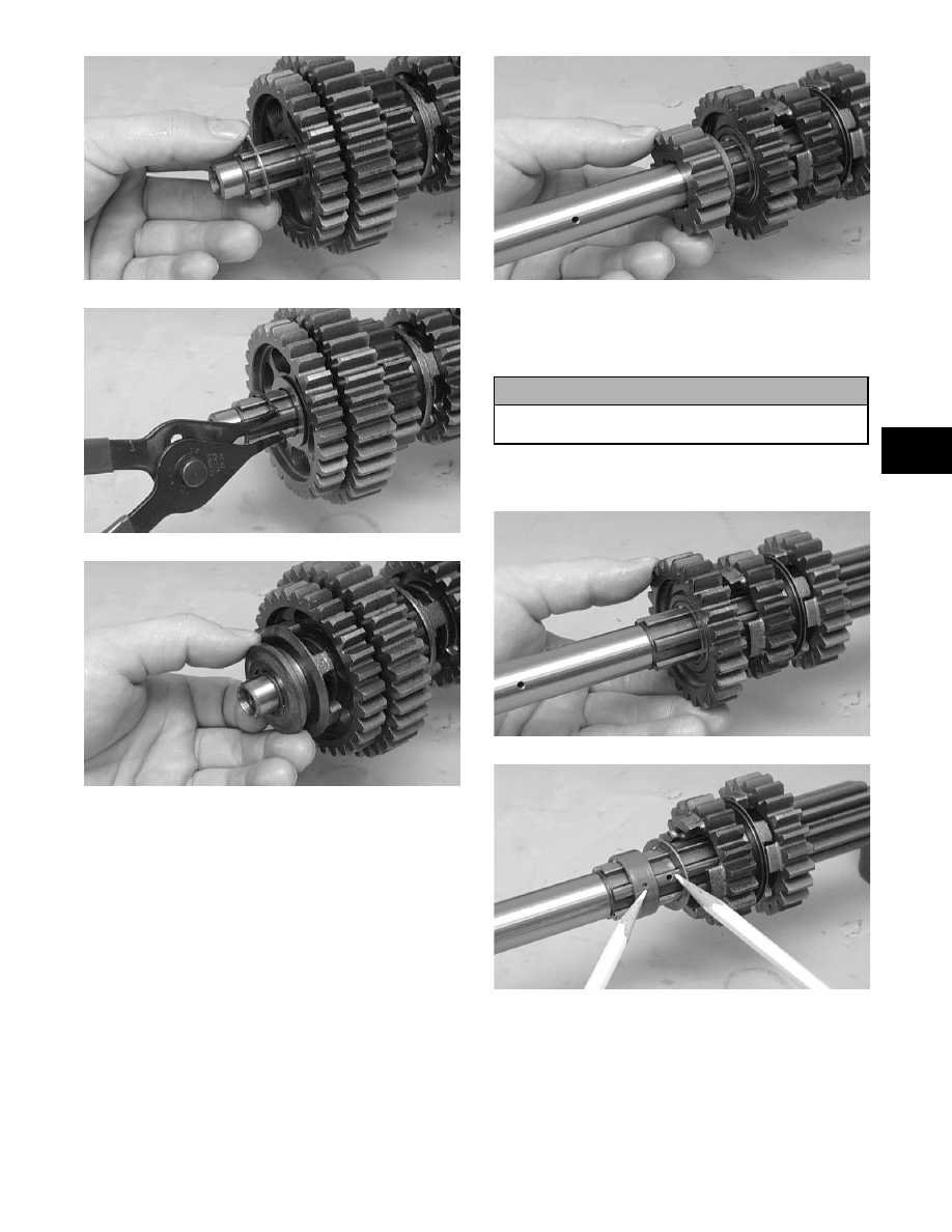
3. Install the 3rd drive gear; then install the 5th drive

circlip onto the countershaft.

77)

4. Install the 5th drive washer and 5th drive gear onto

the countershaft making sure the oil holes align.

7)

7)

7)

5. On the 250/300, press the 2nd drive gear onto the

countershaft leaving an 0.25 mm (0.010 in.) gap

between the 2nd and 5th drive gears.

477#577

30

$ )"*

$ )"*

4$ 4)"*

5$ 5)"*

6$ 5)">

8$ 5)"B

?$  % > 

1

9$ 4)">

7$ 4)"!

$ 5)"!

$ %>

$ )"B

4$ 4)"B

5$ 4)"B

6$ 1",%

8$ 1",*

?$ 1",>

9$ 1",B

7$ 1",!

RepairPro Service Manual

-------------------------------------------------------------------------------------------------------------------------------------------------------------

96

„

  B !   "  


@!!&"(

K67 (

$

6. On the 400/500, install the 2nd drive gear and 2nd

drive washer onto the countershaft.

74)

„

      !&

 $

COUNTERSHAFT 
(Automatic Transmission)

Disassembling

1. Remove drive gear #2; then remove the snap ring

securing the reverse gear dog.

2. Remove the reverse gear dog; then remove the

snap ring securing the reverse driven gear.

3. Remove the reverse driven gear and account for

the washer, bushing, and bearing.

4. Remove the low driven gear washer and lock

washers; then remove the low driven gear.

Account for the bushing and bearing.

5. Remove the washer; then remove the snap ring

securing the sliding dog. Remove the sliding dog.

6. Remove the high driven gear snap ring; then

remove the high driven gear. Account for the

washer, bushing, and bearing.

Assembling

856?

1. Place the high driven gear onto the countershaft

making sure the bearing, bushing, and washer are

properly positioned. Secure with the snap ring.

2. Place the sliding dog onto the countershaft; then

secure with the snap ring. Place the washer next to

the snap ring.

! CAUTION

2   "   &   

 !&$

! CAUTION

        ;

! < = $ ,  ;

!     

   & 

#    $ ,

! & &

 C$

30

$ B

$ B

4$ ()"*

5$ >

6$ .)"*

8$ %)

?$ )"*K

9$ B

7$ >

$ 1")"*

$ 1"*)

$ %!1

4$ (B

5$ (B

-------------------------------------------------------------------------------------------------------------------------------------------------------------

98

3

3. Place the low driven gear onto the countershaft

making sure the bearing and bushing are properly

positioned; then place the lock washers and

washer onto the shaft.

4. Place the reverse driven gear onto the countershaft

making sure the bearing, bushing, and washer are

properly positioned; then secure with the snap

ring.

5. Place the reverse gear dog onto the countershaft;

then secure with the snap ring.

6. Place drive gear #2 onto the countershaft.

„

 B

 &

$

DRIVEN GEAR (400/500)

Disassembling

1. Remove the circlip securing the driven gear.

Account for a spring washer and thrust washer.

?)

2. Note the position of the alignment marks for

installation; then remove the driven gear with

inner race. Account for three pins and six springs.

?)

Inspecting

1. Inspect the gear, pins, and keyway for wear.

2. Inspect the springs for damage or fatigue.

Assembling

1. Align the alignment marks of the driven gear and

inner race.

?)

2. Install three springs (every other one) proceeding

away from the alignment marks.

?4)

3. Using a pair of needle-nose pliers, insert each

remaining spring part way into the slot; then install

a pin and push the spring/pin assembly into the

slot.

?5)

4. Install the thrust washer and spring washer (with

its raised inner portion directed away from the

gear); then install the circlip with the sharp edge

facing away from the gear.

RepairPro Service Manual

-------------------------------------------------------------------------------------------------------------------------------------------------------------

9?

?)

„

   "    !&

 $

-------------------------------------------------------------------------------------------------------------------------------------------------------------

4-1

4

SECTION 4 - 

FUEL/LUBRICATION/COOLING

TABLE OF

CONTENTS

Carburetor Specifications ........................................ 4-2
Carburetor Schematics............................................ 4-3
Carburetor ............................................................... 4-4
Cleaning and Inspecting Carburetor........................ 4-8
Throttle Cable Free-Play ......................................... 4-9
Engine RPM (Idle) ................................................... 4-9
Gas Tank ............................................................... 4-10
Gas Tank Valve  .................................................... 4-11
Gas/Vent Hoses  ................................................... 4-11
Oil Flow Charts...................................................... 4-12
Oil Pump ............................................................... 4-13
Testing Oil Pump Pressure.................................... 4-14
Oil Cooler (250/300/375) ....................................... 4-15
Liquid Cooling System (400/500) .......................... 4-16
Radiator................................................................. 4-17
Hoses/Thermostat................................................. 4-18
Fan ........................................................................ 4-19
Servicing Water Pump 
   (400/500 - Manual Transmission) ....................... 4-19
Servicing Water Pump
   (500 - Automatic Transmission) .......................... 4-20

RepairPro Service Manual

-------------------------------------------------------------------------------------------------------------------------------------------------------------

4-2

Carburetor 

Specifications

ITEM

250

300

375

400

500

Type

Keihin CVK32

Keihin CVK32 Keihin CVK32

Keihin CVK34

Keihin CVK34

Main Jet

138

135

150

145

148

Slow  Jet

38

38

38

38

38

Pilot Air Screw Setting 

(turns)

1 3/4

2 1/4

2 1/8

2 1/4

2 1/4

Needle Jet

4.0/3.4

4.0/3.4

4.0/3.4

6.0/4.0

6.0/4.0

Jet Needle

N8TT

N8TT

N8TV

N601

N601

Idle RPM

1400-1600

1400-1600

1200-1350

1400-1600

1200-1350

Starter  Jet

60

65

60

90

102

Float Arm Height

17 mm

(0.7 in.)

17 mm

(0.7 in.)

17 mm

(0.7 in.)

17 mm

(0.7 in.)

17 mm

(0.7 in.)

Throttle Cable 

Free-Play (at lever)

3-6 mm

(1/8-1/4 in.)

3-6 mm

(1/8-1/4 in.)

3-6 mm

(1/8-1/4 in.)

3-6 mm

(1/8-1/4 in.)

3-6 mm

(1/8-1/4 in.)

-------------------------------------------------------------------------------------------------------------------------------------------------------------

4-3

4

Carburetor Schematics

0735-876

0736-053

250/300/375 (Keihin)

KEY

1. Cover
2. Screw
3. Spring
4. Vacuum Piston
5. Spring Seat
6. Jet Needle
7. Needle Jet
8. Jet Holder
9. Main Jet

10. Slow Jet
11. Starter Jet
12. Float Valve

13. Clip
14. Float Pin
15. Float
16. Drain Plug
17. Screw
18. Pilot Air Screw
19. O-Ring
20. Spring
21. Washer
22. Starter Valve
23. Spring
24. O-Ring
25. Cap
26. Rubber Cap
27. Stop Screw
28. Washer
29. Spring
30. Tube
31. Cover
32. Screw
33. Choke Cable
34. Throttle Cable
35. Idle Adjust Bracket

400/500 (Keihin)

KEY

1. Cover
2. Screw
3. Spring
4. Vacuum Piston
5. Spring Seat
6. Jet Needle
7. Needle Jet
8. Jet Holder
9. Main Jet

10. Slow Jet
11. Starter Jet

12. Float Valve
13. Clip
14. Float Pin
15. Float
16. Drain Plug
17. Screw
18. Pilot Air Screw
19. O-Ring
20. Spring
21. Washer
22. Starter Valve
23. Spring
24. O-Ring
25. Cap
26. Rubber Cap
27. Stop Screw
28. Washer
29. Spring
30. Tube
31. Diaphragm Assy
32. Spring
33. Pump Housing
34. U-Ring

 35. Screw

36. Cover
37. Screw
38. Choke Cable
39. Throttle Cable
40. Float Chamber Assy
41. O-Ring

RepairPro Service Manual

-------------------------------------------------------------------------------------------------------------------------------------------------------------

4-4

Carburetor

REMOVING 

1. Turn the gas tank valve to the OFF position.

2. Remove the seat.

3. Remove the air-intake snorkel (250/300) or the air

cleaner housing cover (375/400/500).

4. Disconnect the hose from the carburetor to the gas

tank at the gas tank valve connection.

5. Loosen the flange clamps; then remove the

carburetor from the two carburetor boots.

6. Remove the screw securing the throttle actuator

cover to the carburetor; then remove the cover.

CC743

7. Remove the throttle cable from the actuator arm.

CC742

8. Loosen the outer jam nut securing the throttle

cable to the carburetor body; then route the cable

out of the way.

CC741

9. By unscrewing the plastic choke cable end,

disconnect the choke cable from the carburetor.

CC740A

10. Disconnect the gas and vent hoses; then remove

the carburetor.

DISASSEMBLING

1. Remove the four Phillips-head screws securing the

top cover; then remove the cover.

CH015D

2. Remove the vacuum piston assembly from the

carburetor body. Account for a spring, spring seat,

and the jet needle.

! WARNING

Whenever any maintenance or inspection is per-
formed on the fuel system during which there may
be fuel leakage, there should be no welding, smok-
ing, open flames, etc., in the area.

-------------------------------------------------------------------------------------------------------------------------------------------------------------

4-5

4

CC746

3. Remove the three screws securing the primer

housing. Account for the diaphragm assembly,

spring, and U-ring (in the housing).

CC748

4. Remove the Phillips-head screws securing the

float chamber; then remove the chamber. Account

for the O-ring.

CC749

CC750

5. Remove the float pin.

CC752

6. Lift the float assembly from the carburetor.

Account for the float needle valve.

CC753

!

NOTE: Note the locations of the jets, air screw,

and holder for disassembling procedures.

RepairPro Service Manual

-------------------------------------------------------------------------------------------------------------------------------------------------------------

4-6

CC761A

7. Secure the needle jet holder with a wrench; then

remove the main jet.

8. Remove the needle jet holder; then remove the

slow jet and the starter jet.

9. Remove the pilot air screw.

CC758

10. Unscrew and remove the idle speed adjuster

assembly. Account for the spring and washer.

ASSEMBLING

1. Screw the idle speed adjuster into the carburetor

making sure the washer and spring are properly

positioned.

2. Install the pilot air screw.

CC758

!

NOTE: Turn the pilot air screw clockwise until it

is lightly seated; then turn it counterclockwise the
recommended number of turns as an initial set-
ting.

!

NOTE: Note the locations of the jets and holder

during assembling procedures.

CC759A

CC761A

3. Install the slow jet. Tighten securely.

4. Install the main jet into the needle jet holder and

tighten securely; then install the needle jet holder

assembly into the carburetor and tighten securely.

5. Place the float assembly (with float needle valve)

into position and secure to the carburetor with the

float pin.

CC753

-------------------------------------------------------------------------------------------------------------------------------------------------------------

4-7

4

!

NOTE: Check float arm height by inverting the

carburetor freeing the float arm; then measure
with a caliper the height when the float arm is in
contact with the needle valve. Float arm height
should be 17 mm (0.7 in.).

6. Place the float chamber into position making sure

the O-ring is properly positioned; then secure with

the Phillips-head screws.

CC750

CC749

7. Place the U-ring into the primer housing. Position

the spring and diaphragm assembly (lip toward the

carburetor) onto the carburetor; then secure the

assembly with the primer housing and three

screws. Tighten securely.

CC748

8. Place the jet needle, spring seat, and spring into

the vacuum piston; then place the assembly down

into the carburetor.

CC746

9. Place the top cover into position; then secure with

the Phillips-head screws. Tighten securely.

CH015D

INSTALLING 

1. Connect the gas and vent hoses onto the

carburetor.

2. Connect the choke cable by screwing the plastic

choke cable end onto the carburetor.

! CAUTION

It is important to press down on the primer
housing until it contacts the carburetor to make
sure the diaphragm lip is properly seated in the
groove in the carburetor. If the diaphragm is not
properly seated, leakage will occur.

RepairPro Service Manual

-------------------------------------------------------------------------------------------------------------------------------------------------------------

4-8

CC740A

3. Place the throttle cable into position and secure by

tightening the outer jam nut.

CC741

4. Connect the throttle cable to the actuator arm.

CC742

5. Place the throttle actuator cover into position on

the carburetor; then secure with the screw.

CC743

6. Position the carburetor in the air cleaner boot and

intake pipe assembly; then secure with the clamps.

7. Connect the hose at the gas tank valve connection.

8. Secure the air-intake snorkel (250/300) or the air

cleaner housing cover (375/400/500).

9. Install the seat; then turn the gas tank valve to the

ON position.

Cleaning and Inspecting 

Carburetor

!

NOTE: Whenever a part is worn excessively,

cracked, or damaged in any way, replacement is
necessary.

1. Place all metallic components in a wire basket and

submerge in carburetor cleaner.

2. Soak for 30 minutes; then rinse with fresh

parts-cleaning solvent.

3. Wash all non-metallic components with soap and

water. Rinse thoroughly.

4. Dry all components with compressed air only

making sure all holes, orifices, and channels are

unobstructed.

5. Inspect the carburetor body for cracks, nicks,

stripped threads, and any other imperfections in

the casting.

! WARNING

When drying components with compressed air,
always wear safety glasses.

! CAUTION

DO NOT place any non-metallic components in
parts-cleaning solvent because damage or
deterioration will result.

-------------------------------------------------------------------------------------------------------------------------------------------------------------

4-9

4

6. Inspect the vacuum piston/diaphragm for cracks,

imperfections in the casting, or cracks and tears in

the rubber.

7. Inspect float for damage.

8. Inspect gasket and O-rings for distortion, tears, or

noticeable damage.

9. Inspect tips of the jet needle, pilot screw, and the

inlet needle valve for wear, damage, or distortion.

10. Inspect the pilot jet/slow jet and main jet for

obstructions or damage.

!

NOTE: If the pilot jet is obstructed, the mixture

will be extremely lean at idle and part-throttle oper-
ation.

11. Inspect the plunger assembly/starter valve and seat

for wear or damage.

12. Inspect the carburetor mounting flange for damage

and tightness.

Throttle Cable

Free-Play

1. Check throttle cable free-play at the lever;

free-play should be 3-6 mm (1/8 - 1/4 in.).

2. To adjust, slide the rubber boot away from the

adjuster located near the throttle lever. Loosen the

jam nut and rotate the adjuster in the appropriate

direction until proper free-play is attained. Tighten

the jam nut against the adjuster; then slide the

rubber boot over the adjuster.

ATV-0047

Engine RPM (Idle)

To properly adjust the idle RPM, a tachometer is nec-

essary.

To adjust idle RPM, use the following procedure.

1. Start the engine and warm it up to operating

temperature.

2. Turn the idle adjustment screw clockwise or

counterclockwise until the engine idles at

recommended RPM.

CC795B

AF920C

! WARNING

Adjust the idle to the correct RPM. Make sure the
engine is fully warm before adjusting the idle RPM.

Engine Idle RPM

250/300/400

1400-1600

375/500

1200-1350

Adjustment Screw

250/300

RepairPro Service Manual

-------------------------------------------------------------------------------------------------------------------------------------------------------------

4-10

Gas Tank

0735-524

REMOVING

1. Turn the gas tank valve to the OFF position.

2. Remove the seat.

3. Remove the air-intake snorkel (250/300) or the air

cleaner housing cover (375/400/500).

CH040DA

CH041DA

AL645DA

4. Disconnect the hose from the carburetor to the gas

tank at the tank connection.

5. Cut the tie-down securing the fuel hose to the

cables and hoses.

6. Remove the torx-head screws securing the gas

tank to the frame. 

AL617D

7. Remove the vent hose; then remove the gas tank.

CLEANING AND INSPECTING

!

NOTE: Whenever a part is worn excessively,

cracked, or damaged in any way, replacement is
necessary.

1. Clean all gas tank components with parts-cleaning

solvent.

2. Inspect all hoses for cracks or leaks.

! WARNING

Whenever any maintenance or inspection is made
on the fuel system during which there may be fuel
leakage, there should be no welding, smoking,
open flames, etc., in the area.

KEY

1. Gas Tank Assy
2. Tank Cap
3. Vent Hose
4. Fuel Hose
5. Hose Clamp
6. Gas Tank Valve
7. Valve Knob
8. Screw
9. Lock Nut

10. Screw
11. Valve Gasket

-------------------------------------------------------------------------------------------------------------------------------------------------------------


Content      ..     14      15      16      17     ..