Suzuki GSX-R1000. Service Manual - part 3


  Index      Manuals     Suzuki GSX-R1000. Service Manual


Search            copyright infringement  


Content      ..     1      2      3      4      ..


Suzuki GSX-R1000. Service Manual - part 3


0B-11 Maintenance and Lubrication: 

7) Hold the motorcycle vertically and check the oil level 

through the inspection window (3). The oil level 
should be between the low level “L” and full level “F”.

Oil Level Inspection

1) Place the motorcycle on the side-stand.

2) Start up the engine and allow it to run for several 

minutes at idle speed.

3) Turn off the engine and wait about three minutes.

4) Hold the motorcycle vertically and check the oil level 

through the inspection window (1). The oil level 
should be between the low level “L” and full level “F”.

Oil Filter Replacement

1) Remove the right side cowling. Refer to “Exterior 

Parts Removal and Installation” in Section 9D 
(Page 9D-6).

2) Drain engine oil as described in the engine oil 

replacement procedure.

3) Remove the oil filter (1) using the special tool.

Special tool

(A):  09915–40610 (Oil filter wrench)

4) Apply engine oil lightly to the O-ring of new oil filter, 

before installation.

CAUTION

!


ONLY USE A GENUINE SUZUKI 
MOTORCYCLE OIL FILTER. 
Other manufacturer’s oil filters may differ in 
thread specifications (thread diameter and 
pitch), filtering performance and durability 
which may lead to engine damage or oil 
leaks. Also, do not use a genuine Suzuki 
automobile oil filter on this motorcycle.


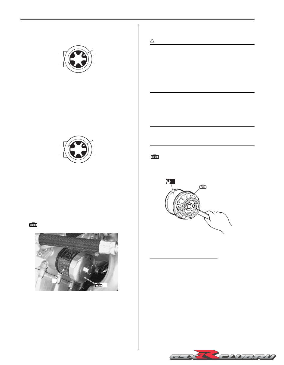
5) Install new oil filter. Turn it by hand until you feel that 

the oil filter O-ring contacts the oil filter mounting 
surface. Then, tighten the oil filter two full turns (or to 
specified torque) using the special tool.

NOTE

To properly tighten the oil filter, use the 
special tool. Never tighten the oil filter by 
hand only.


Special tool

(A):  09915–40610 (Oil filter wrench)

Tightening torque
Oil filter (a):  20 N·m (2.0 kgf-m, 14.5 lbf-ft)

6) Add new engine oil and check the oil level is as 

described in the engine oil replacement procedure.

Necessary amount of engine oil
Oil change: 2 800 ml (3.0/2.5 US/lmp qt)
Oil and filter change: 3 300 ml (3.5/3.0 US/lmp qt)
Engine overhaul: 3 600 ml (2.8/3.2 US/lmp qt)

F

L

3

I815H1020023-01

F

L

1

I815H1020024-01

(A)

1

I947H1020012-01

(a)

(A)

I823H1020041-01

-------------------------------------------------------------------------------------------------------------------------------------------------------------

Maintenance and Lubrication:  0B-12

Throttle Cable Play Inspection and Adjustment

B947H10206011

Inspect throttle cable play
Initially at 1 000 km (600 miles, 2 months) and every 
6 000 km (4 000 miles, 12 months) thereafter

Inspect and adjust the throttle cable play “a” as follows:

Throttle cable play “a”
2.0 – 4.0 mm (0.08 – 0.16 in)

1) Remove the boot (1).

2) Loosen the lock-nut (2) of the throttle pulling cable.

3) Turn the adjuster (3) in or out until the throttle cable 

play “a” (at the throttle grip) is within 2 – 4 mm (0.08 
– 0.16 in).

4) Tighten the lock-nut (2) while holding the adjuster 

(3).

5) Fit the boot (1) positively onto the adjuster.

WARNING

!


After the adjustment is completed, check that 
handlebar movement does not raise the 
engine idle speed and that the throttle grip 
returns smoothly and automatically.


PAIR System Inspection

B947H10206012

Inspect PAIR system
Every 12 000 km (7 500 miles, 24 months)

Inspect the PAIR (air supply) system periodically. Refer 
to “PAIR System Inspection” in Section 1B (Page 1B-9).

Throttle Valve Synchronization

B947H10206013

Inspect throttle valve synchronization
Initially at 1 000 km (600 miles, 2 months) (E-33 only) 
and every 12 000 km (7 500 miles, 24 months)

Inspect the throttle valve synchronization periodically. 
Refer to “Throttle Valve Synchronization” in Section 1D 
(Page 1D-16).

Cooling System Inspection

B947H10206014

Inspect cooling system
Every 6 000 km (4 000 miles, 6 months)

Replace engine coolant
Every 2 years

Engine Coolant Level Inspection

1) Hold the motorcycle vertically.

2) Check the engine coolant level by observing the “F” 

and “L” lines on the engine coolant reservoir tank. If 
the level is below the “L” line, add engine coolant to 
the “F” line from the engine coolant reservoir tank 
filler (1) behind the right side cowling. Refer to 
“Exterior Parts Removal and Installation” in Section 
9D (Page 9D-6).

“ a ”

I947H1020038-01

1

3

2

I947H1020013-02

I947H1020035-01

1

I947H1020054-02

-------------------------------------------------------------------------------------------------------------------------------------------------------------

0B-13 Maintenance and Lubrication: 

Engine Coolant Change

Refer to “Engine Coolant Description” in Section 1F 
(Page 1F-1)
.

WARNING

!


Do not open the radiator cap when the engine 
is hot, as you may be injured by escaping hot 
liquid or vapor. Engine coolant may be 
harmful if swallowed or if it comes in contact 
with skin or eyes. If engine coolant gets into 
the eyes or in contact with the skin, flush 
thoroughly with plenty of water. If swallowed, 
induce vomiting and call physician 
immediately.


1) Remove the right side cowling. Refer to “Exterior 

Parts Removal and Installation” in Section 9D 
(Page 9D-6).

2) Remove the radiator cap (1).

3) Drain engine coolant by disconnecting the radiator 

outlet hose (2) and cylinder inlet hose (3).

4) Flush the radiator with fresh water if necessary.

5) Reconnect the hoses.

6) Pour the specified engine coolant up to the radiator 

inlet.

Engine coolant capacity (excluding reservoir)
2 500 ml (2.6/2.2 US/lmp qt)

7) Bleed air from the cooling circuit.

8) After changing engine coolant, reinstall the removed 

parts. 

Air Bleeding From the Cooling Circuit

1) Remove the side cowlings. Refer to “Exterior Parts 

Removal and Installation” in Section 9D (Page 9D-
6).

2) Add engine coolant up to the radiator inlet.

3) Support the motorcycle upright.

4) Slowly swing the motorcycle, right and left, to bleed 

the air trapped in the cooling circuit.

5) Add engine coolant up to the radiator inlet.

6) Start up the engine and bleed air from the radiator 

inlet completely.

7) Repeat the procedures 5) to 6) until no air bleeds 

from the radiator inlet.

8) Lift and support the fuel tank. Refer to “Fuel Tank 

Removal and Installation” in Section 1G (Page 1G-
9).

9) Loosen the air bleeder bolt (1) and (2), then check 

the engine coolant flows out.

10) Tighten the air bleeder bolt.

Tightening torque
Water pump air bleeder bolt:  13 N·m (1.3 kgf-m, 
4.5 lbf-ft)

11) Close the radiator cap securely.

12) After warming up and cooling down the engine 

several times, add the engine coolant up to the full 
level of the reservoir.

CAUTION

!


Make sure that the radiator is filled with 
engine coolant up to the reservoir full level.


13) Reinstall the removed parts.

Radiator Hose Inspection

Check the radiator hoses for crack, damage or engine 
coolant leakage. Refer to “Water Hose Inspection” in 
Section 1F (Page 1F-7).

1

I947H1020014-03

2

3

I947H1020015-01

1

2

I947H1020016-02

-------------------------------------------------------------------------------------------------------------------------------------------------------------

Maintenance and Lubrication:  0B-14

Clutch Cable Play Inspection and Adjustment

B947H10206015

Inspect clutch cable play
Every 6 000 km (4 000 miles, 12 months)

Inspect and adjust the clutch cable play “a” as follows.

Clutch cable play “a”
10 – 15 mm (0.4 – 0.6 in)

1) Lift and support the fuel tank. Refer to “Fuel Tank 

Removal and Installation” in Section 1G (Page 1G-
9)
.

2) Turn in the adjuster (1) all the way into the clutch 

lever assembly.

3) Loosen the lock-nut (2) and turn the clutch cable 

adjuster (3) to obtain proper cable play.

4) Remove the clutch release adjuster cap (4).

5) Loosen the lock-nut (5) and turn out the clutch 

release adjusting screw (6) two or three rotations.

6) From that position, slowly turn in the clutch release 

adjusting screw (6) until resistance is felt.

7) From this position, turn out the clutch release 

adjusting screw (6) 1 rotation, and tighten the lock-
nut (5) while holding the screw (6).

Tightening torque
Clutch release adjusting screw lock-nut:  6 N·m (
0.6 kgf-m, 4.5 lbf-ft)

8) Turn the cable adjuster (3) to obtain 10 – 15 mm (0.4 

– 0.6 in) of free play “a” at the clutch lever end.

9) Tighten the lock-nut (2).

10) Install the clutch release adjuster cap (4).

Tightening torque
Clutch release adjuster cap:  11 N·m (1.1 kgf-m, 
8.0 lbf-ft)

11) Reinstall the fuel tank.

Drive Chain Inspection and Adjustment

B947H10206016

Inspect drive chain
Initially at 1 000 km (600 miles, 2 months) and every 
6 000 km (4 000 miles, 12 months) thereafter

Drive Chain Visual Check

1) With the transmission in neutral, support the 

motorcycle using a jack and turn the rear wheel 
slowly by hand.

“ a ”

I947H1020055-01

1

I947H1020017-02

3

2

I947H1020018-02

4

6

5

I947H1020019-01

3

2

I947H1020018-02

-------------------------------------------------------------------------------------------------------------------------------------------------------------

0B-15 Maintenance and Lubrication: 

2) Visually check the drive chain for the possible 

defects listed as follows. If any defects are found, the 
drive chain must be replaced. Refer to “Drive Chain 
Replacement” in Section 3A (Page 3A-7)
.

• Loose pins

• Damaged rollers

• Dry or rusted links

• Kinked or binding links

• Excessive wear

• Improper chain adjustment

• Missing O-ring seals

NOTE

When replacing the drive chain, replace the 
drive chain and sprockets as a set.


Drive Chain Length Inspection

1) Loosen the axle nut (1).

2) Loosen the left and right chain adjuster lock-nuts (2).

3) Give tension to the drive chain fully by turning both 

chain adjuster bolts (3).

4) Count out 21 pins (20 pitches) on the chain and 

measure the distance between the two points. If the 
distance exceeds the service limit, the chain must be 
replaced.

Drive chain 20-pitch length
Service limit: 319.4 mm (12.57 in)

5) After finishing the drive chain length inspection, 

adjust the drive chain slack.

Drive Chain Slack Adjustment

1) Support the motorcycle with a jack.

2) Loosen the axle nut (1).

3) Loosen the left and right chain adjuster lock-nuts (2).

4) Loosen or tighten both chain adjuster bolts (3) until 

there is 20 – 30 mm (0.8 – 1.2 in) of slack “a” at the 
middle of the chain between the engine and rear 
sprockets as shown in the figure.

CAUTION

!


The reference marks “A” on both sides of the 
swingarm and the edge of each chain 
adjuster must be aligned to ensure that the 
front and rear wheels are correctly aligned.


Drive chain slack “a”
Standard: 20 – 30 mm (0.8 – 1.2 in)

5) After adjusting the drive chain, tighten the axle nut 

(1) to the specified torque.

Tightening torque
Rear axle nut:  100 N·m (10.0 kgf-m, 72.5 lbf-ft)

6) Tighten both chain adjuster lock-nuts (2) securely.

7) Recheck the drive chain slack after tightening the 

axle nut.

1. O-ring seal

2. Grease

2

1

I649G1020032-02

1

2

3

I947H1020020-01

1 2 3

19 20 21

I649G1020034-02

1

2

3

“A”

I947H1020021-01

“a”

I649G1020036-02

-------------------------------------------------------------------------------------------------------------------------------------------------------------

Maintenance and Lubrication:  0B-16

Drive Chain Cleaning and Lubricating

B947H10206017

Clean and lubricate drive chain
Every 1 000 km (600 miles)

Clean and lubricate the drive chain in the following 
procedures:

1) Clean the drive chain with kerosine. If the drive chain 

tends to rust quickly, the intervals must be 
shortened.

CAUTION

!


Do not use trichloroethylene, gasoline or any 
similar solvent.
These fluids have too great dissolving power 
for this chain and they can damage the O-
rings. Use only kerosine to clean the drive 
chain.


2) After cleaning and drying the chain, oil it with a 

heavyweight motor oil.

CAUTION

!


• Do not use any oil sold commercially as 

“drive chain oil”. Such oil can damage the 
O-rings.

• The standard drive chain is a DID 50VAZ. 

SUZUKI recommends to use this standard 
drive chain as a replacement.


Brake System Inspection

B947H10206018

Inspect brake system
Initially at 1 000 km (600 miles, 2 months) and every 
6 000 km (4 000 miles, 12 months) thereafter

Inspect brake hose and brake fluid
Every 6 000 km (4 000 miles, 12 months)

WARNING

!


• The brake system of this motorcycle is 

filled with a glycol-based brake fluid. Do 
not use or mix different types of fluid such 
as silicone-based and petroleum-based 
fluids. Do not use any brake fluid taken 
from old, used or unsealed containers. 
Never reuse brake fluid left over from the 
last servicing or stored for a long period of 
time.

• Brake fluid, if it leaks, will interfere with 

safe running and immediately discolor 
painted surfaces. Check the brake hoses 
and hose joints for cracks and oil leakage 
before riding.


Brake Fluid Level Check

1) Keep the motorcycle upright and place the 

handlebars straight.

2) Check the brake fluid level by observing the lower 

limit line “A” on the front and rear brake fluid 
reservoirs. When the brake fluid level is below the 
lower limit line “A”, replenish with brake fluid that 
meets the following specification.

BF:  Brake fluid  (DOT 4)

I947H1020022-01

“A”

I947H1020023-01

“A”

I947H1020024-02

-------------------------------------------------------------------------------------------------------------------------------------------------------------

0B-17 Maintenance and Lubrication: 

Brake Pads Check

The extent of brake pad wear can be checked by 
observing the grooved limit line “A” on the pads. When 
the wear exceeds the grooved limit line, replace the 
pads with new ones. Refer to “Front Brake Pad 
Replacement” in Section 4B (Page 4B-2) 
and “Rear 
Brake Pad Replacement” in Section 4C (Page 4C-2).

CAUTION

!


Replace the brake pads as a set, otherwise 
braking performance will be adversely 
affected.


Front and Rear Brake Hose Inspection

Inspect the brake hoses and hose joints for crack, 
damage or brake oil leakage. If any defects are found, 
replace the brake hose with a new one. Refer to “Front 
Brake Hose Removal and Installation” in Section 4A 
(Page 4A-8) 
and “Rear Brake Hose Removal and 
Installation” in Section 4A (Page 4A-8)
.

Brake Pedal Height Inspection and Adjustment

1) Inspect the brake pedal height “a” between the pedal 

top face and footrest.
Adjust the brake pedal height if necessary.

Brake pedal height “a”
Standard: 65 – 75 mm (2.6 – 3.0 in)

2) Loosen the lock-nut (1).

3) Turn the push rod (2) until the brake pedal becomes 

65 – 75 mm (2.6 – 3.0 in) “a” below the top of the 
footrest.

4) Tighten the lock-nut (1) securely.

Tightening torque
Rear master cylinder rod lock-nut (a):  17 N·m (
1.7 kgf-m, 12.5 lbf-ft)

Brake Hose Replacement

Replace brake hose
Every 4 years

Refer to “Front Brake Hose Removal and Installation” in 
Section 4A (Page 4A-8)
 and “Rear Brake Hose Removal 
and Installation” in Section 4A (Page 4A-8).

Brake Fluid Replacement

Replace brake fluid
Every 2 years

Refer to “Brake Fluid Replacement” in Section 4A 
(Page 4A-6).

“A”

I947H1020025-02

“A”

I947H1020026-03

I947H1020027-01

I947H1020028-03

2

(a)

1

“ a ”

I947H1020029-01

-------------------------------------------------------------------------------------------------------------------------------------------------------------

Maintenance and Lubrication:  0B-18

Air Bleeding from Brake Fluid Circuit

Refer to “Air Bleeding from Brake Fluid Circuit” in 
Section 4A (Page 4A-4).

Rear Brake Light Switch Adjustment

Refer to “Rear Brake Light Switch Inspection and 
Adjustment” in Section 4A (Page 4A-4).

Tire Inspection

B947H10206019

Inspect tire
Every 6 000 km (4 000 miles, 12 months)

Tire Tread Condition

Operating the motorcycle with excessively worn tires will 
decrease riding stability and consequently invite a 
dangerous situation. It is highly recommended to replace 
a tire when the remaining depth of tire tread reaches the 
following specification.

Special tool

:  09900–20805 (Tire depth gauge)

Tire tread depth (Service limit)
Front: 1.6 mm (0.06 in)
Rear: 2.0 mm (0.08 in)

Tire Pressure

If the tire pressure is too high or too low, steering will be 
adversely affected and tire wear increased. Therefore, 
maintain the correct tire pressure for good roadability, or 
shorter tire life will result. Cold inflation tire pressure is as 
follows.

Cold inflation tire pressure

CAUTION

!


The standard tire fitted on this motorcycle is 
120/70 ZR17 M/C (58W) for front and 190/50 
ZR17 M/C (73W) for rear. The use of tires 
other than those specified may cause 
instability. It is highly recommended to use 
the specified tires.


Tire type
BRIDGESTONE

• Front: BT016F N

• Rear: BT016R N

Steering System Inspection

B947H10206020

Inspect steering system
Initially at 1 000 km (600 miles, 2 months) and every 
12 000 km (7 500 miles, 24 months) thereafter

Steering should be adjusted properly for smooth turning 
of handlebars and safe running. Overtighten steering 
prevents smooth turning of the handlebars and too loose 
steering will cause poor stability.

1) Check that there is no play in the front fork.

2) Support the motorcycle so that the front wheel is off 

the ground, with the wheel facing straight ahead, 
grasp the lower fork tubes near the axle and pull 
forward.
If play is found, readjust the steering. Refer to 
“Steering Tension Adjustment” in Section 6B 
(Page 6B-11).

Solo riding

Dual riding

kPa

kgf/cm

2

psi

kPa

kgf/cm

2

psi

Front

250

2.50

36

250

2.50

36

Rear

290

2.90

42

290

2.90

42

I310G1020068-02

I310G1020069-02

I947H1020030-02

-------------------------------------------------------------------------------------------------------------------------------------------------------------

0B-19 Maintenance and Lubrication: 

Front Fork Inspection

B947H10206021

Inspect front fork
Every 12 000 km (7 500 miles, 24 months)

Inspect the front forks for oil leakage, scoring or 
scratches on the outer surface of the inner tubes. 
Replace any defective parts, if necessary. Refer to 
“Front Fork Disassembly and Assembly” in Section 2B 
(Page 2B-4).

Rear Suspension Inspection

B947H10206022

Inspect rear suspension
Every 12 000 km (7 500 miles, 24 months)

Inspect the rear shock absorber for oil leakage and 
check that there is no play in the swingarm.
Replace any defective parts, if necessary. Refer to “Rear 
Shock Absorber Removal and Installation” in Section 2C 
(Page 2C-3), “
Cushion Lever Removal and Installation” 
in Section 2C (Page 2C-7) 
and “Swingarm Removal and 
Installation” in Section 2C (Page 2C-9).

Chassis Bolt and Nut Inspection

B947H10206023

Tighten chassis bolt and nut
Initially at 1 000 km (600 miles, 2 months) and every 
6 000 km (4 000 miles, 12 months) thereafter

Check that all chassis bolts and nuts are tightened to 
their specified torque. 

I947H1020031-01

I947H1020032-01

I947H1020039-01

Steering stem lock-nut 80 N

m (8.0 kgf-m, 58.0 lbf-ft)

Steering stem head nut 90 N

m (9.0 kgf-m, 65.0 lbf-ft)

Front fork upper clamp bolt 23 N

m (2.3 kgf-m, 16.5 lbf-ft)

Handlebar clamp bolt 23 N

m (2.3 kgf-m, 16.5 lbf-ft)

Front brake master cylinder mounting bolt 10 N

m (1.0 kgf-m, 7.0 

lbf-ft)

Brake hose union bolt 23 N

m (2.3 kgf-m, 16.5 lbf-ft)

Front master cylinder air bleeder valve 6 N

m (0.6 kgf-m, 4.5 lbf-

ft)

Front fork lower clamp bolt 23 N

m (2.3 kgf-m, 16.5 lbf-ft)

Steering damper bolt/nut 23 N

m (2.3 kgf-m, 16.5 lbf-ft)

(c)

3

(a)

1

(b)

2

(c)

4

I947H1020040-01

(e)

7

(e)

7

(d)

5

(c)

6

I947H1020041-02

(c)

8

(c)

9

I947H1020042-01

-------------------------------------------------------------------------------------------------------------------------------------------------------------

Maintenance and Lubrication:  0B-20

Brake hose union bolt 23 N

m (2.3 kgf-m, 16.5 lbf-ft)

10 

Front axle bolt 100 N

m (10.0 kgf-m, 72.5 lbf-ft)

11 

Front axle pinch bolt 23 N

m (2.3 kgf-m, 16.5 lbf-ft)

12 

Front brake disc bolt 18 N

m (1.8 kgf-m, 13.0 lbf-ft)

13 

Front brake caliper mounting bolt 39 N

m (3.9 kgf-m, 28.0 lbf-ft)

14 

Brake caliper air bleeder valve 7.5 N

m (0.75 kgf-m, 5.5 lbf-ft)

15 

Swingarm pivot nut 100 N

m (10.0 kgf-m, 72.5 lbf-ft)

16 

Front footrest bracket bolt 23 N

m (2.3 kgf-m, 16.5 lbf-ft)

Brake hose union bolt 23 N

m (2.3 kgf-m, 16.5 lbf-ft)

16 

Front footrest bracket bolt 23 N

m (2.3 kgf-m, 16.5 lbf-ft)

17 

Swingarm pivot lock-nut 90 N

m (9.0 kgf-m, 65.0 lbf-ft)

18 

Rear brake master cylinder mounting bolt 10 N

m (1.0 kgf-m, 7.0 

lbf-ft)

19 

Rear brake master cylinder rod lock-nut 18 N

m (1.8 kgf-m, 13.0 

lbf-ft)

(f)

10

(c)

11

(g)

12

(h)

13

(i)

14

(c)

6

I947H1020043-02

(f)

15

(c)

16

(c)

16

I947H1020044-03

(c)

16

(c)

16

(d)

18

(c)

6

(b)

17

(g)

19

I947H1020045-03

20 

Rear shock absorber bracket nut 115 N

m (11.5 kgf-m, 83.0 lbf-ft)

21 

Rear shock absorber mounting bolt/nut (Upper and Lower) 50 
N

m (5.0 kgf-m, 36.0 lbf-ft)

22 

Cushion rod bolt/nut (Front and Rear) 98 N

m (9.8 kgf-m, 71.0 lbf-

ft)

23 

Cushion lever mounting bolt/nut 98 N

m (9.8 kgf-m, 71.0 lbf-ft)

24 

Rear axle nut 100 N

m (10.0 kgf-m, 72.5 lbf-ft)

25 

Rear sprocket nut 60 N

m (6.0 kgf-m, 43.5 lbf-ft)

(j)

20

I947H1020046-02

(l)

22

(k)

21

(k)

21

(l)

23

I947H1020047-02

(m)

25

(f)

24

I947H1020048-02

-------------------------------------------------------------------------------------------------------------------------------------------------------------

0B-21 Maintenance and Lubrication: 

Compression Pressure Check

B947H10206024

Refer to “Compression Pressure Check” in Section 1D 
(Page 1D-3).

Oil Pressure Check

B947H10206025

Refer to “Oil Pressure Check” in Section 1E (Page 1E-
5)
.

SDS Check

B947H10206026

Refer to “SDS Check” in Section 1A (Page 1A-16).

Specifications

Tightening Torque Specifications

B947H10207001

NOTE

The specified tightening torque is described in the following.
“Chassis Bolt and Nut Inspection” (Page 0B-19)


Reference:

For the tightening torque of fastener not specified in this section, refer to “Tightening Torque List” in Section 0C 
(Page 0C-9).

Brake hose union bolt 23 N

m (2.3 kgf-m, 16.5 lbf-ft)

14 

Brake caliper air bleeder valve 6 N

m (0.6 kgf-m, 4.5 lbf-ft)

26 

Rear brake disc bolt 35 N

m (3.5 kgf-m, 25.5 lbf-ft)

27 

Rear brake caliper sliding pin (Front) 27 N

m (2.7 kgf-m, 19.5 lbf-

ft)

28 

Rear brake caliper sliding pin (Rear) 12 N

m (1.2 kgf-m, 8.5 lbf-ft)

(c)

6

(o)

27

(n)

26

(e)

14

(p)

28

I947H1020049-04

Fastening part

Tightening torque

Note

N

m

kgf-m

lbf-ft

Exhaust pipe bolt

23

2.3 

16.5 

)

(Page 0B-4)

Muffler chamber connecting bolt

30

3.0 

21.5 

)

(Page 0B-4)

Muffler chamber bracket bolt

25

2.5 

18.0 

)

(Page 0B-4)

Muffler chamber mounting bolt

23

2.3 

16.5 

)

(Page 0B-4)

Muffler connecting bolt

23

2.3 

16.5 

)

(Page 0B-4)

Muffler mounting bolt

25

2.5 

18.0 

)

(Page 0B-4)

Spark plug

11

1.1 8.0 

)

(Page 0B-9) / 

)

(Page 0B-9) / 

)

(Page 0B-9)

Oil drain plug

23

2.3 

16.5 

)

(Page 0B-10)

Oil filter

20

2.0 

14.5 

)

(Page 0B-11)

Water pump air bleeder bolt

13

1.3 

4.5 

)

(Page 0B-13)

Clutch release adjusting screw lock-nut

6

0.6 

4.5 

)

(Page 0B-14)

Clutch release adjuster cap

11

1.1 

8.0 

)

(Page 0B-14)

Rear axle nut

100

10.0 

72.5 

)

(Page 0B-15)

Rear master cylinder rod lock-nut

17

1.7 

12.5 

)

(Page 0B-17)

-------------------------------------------------------------------------------------------------------------------------------------------------------------

Maintenance and Lubrication:  0B-22

Special Tools and Equipment

Recommended Service Material

B947H10208001

NOTE

Required service material is also described in the following.
“Lubrication Points” (Page 0B-3)


Special Tool

B947H10208002

Material

SUZUKI recommended product or Specification

Note

Brake fluid

DOT 4

)

(Page 0B-16)

09900–20803

09900–20805

Thickness gauge

Tire depth gauge

)

(Page 0B-6)

)

(Page 0B-18)

09915–40610
Oil filter wrench

)

(Page 0B-11) / 

)

(Page 0B-11)

-------------------------------------------------------------------------------------------------------------------------------------------------------------

0C-1 Service Data: 

General Information

Service Data

Specifications

Service Data

B947H10307001

Valve + Guide

Unit: mm (in)

Camshaft + Cylinder Head

Unit: mm (in)

Item

Standard

Limit

Valve diam.

IN.

31.0 (1.22)

EX.

25.0 (0.98)

Valve clearance (when cold)

IN.

0.08 – 0.18 (0.003 – 0.007)

EX.

0.18 – 0.28 (0.007 – 0.011)

Valve guide to valve stem clearance

IN.

0.010 – 0.037 (0.0004 – 0.0015)

EX.

0.030 – 0.057 (0.0012 – 0.0022)

Valve guide I.D.

IN. & EX.

4.500 – 4.512 (0.1772 – 0.1776)

Valve stem O.D.

IN.

4.475 – 4.490 (0.1762 – 0.1768)

EX.

4.455 – 4.470 (0.1754 – 0.1760)

Valve stem deflection

IN. & EX.

0.25 (0.010)

Valve stem runout

IN. & EX.

0.05 (0.002)

Valve seat width

IN. & EX.

0.9 – 1.1 (0.035 – 0.043)

Valve head radial runout

IN. & EX.

0.03 (0.001)

Valve spring free length

Inner

30.1 (1.19)

Outer

35.3 (1.39)

Valve spring tension

Inner

31.3 – 38.3 N (3.2 – 3.9 kgf, 7.0 – 8.6 lbs)

at length 27.55 mm (1.085 in)

Outer

91.3 – 105.1 N (9.3 – 10.7 kgf, 20.5 – 23.6 

lbs)

at length 33.05 mm (1.301 in)

Item

Standard

Limit

Cam height

IN.

37.68 – 37.73 (1.483 – 1.485)

37.38 (1.472)

EX.

36.88 – 36.93 (1.452 – 1.454)

36.58 (1.440)

Camshaft journal oil clearance

IN. & EX.

0.032 – 0.066 (0.0013 – 0.0026)

0.150 (0.0059)

Camshaft journal holder I.D.

IN. & EX.

24.012 – 24.025 (0.9454 – 0.9459)

Camshaft journal O.D.

IN. & EX.

23.959 – 23.980 (0.9433 – 0.9441)

Camshaft runout

0.10 (0.004)

Cam chain pin (at arrow “3”)

14th pin

Cylinder head distortion

0.02 (0.0008)

-------------------------------------------------------------------------------------------------------------------------------------------------------------

Service Data:  0C-2

Cylinder + Piston + Piston Ring

Unit: mm (in)

Conrod + Crankshaft 

Unit: mm (in)

Item

Standard

Limit

Compression pressure

1 400 – 1 800 kPa (14 – 18 kgf/cm

2

, 199 – 256 psi)

1 000 kPa

(10 kgf/cm

2

142 psi)

Compression pressure difference

200 kPa

(2 kgf/cm

2

, 28 psi)

Piston-to-cylinder clearance

0.030 – 0.040 (0.0012 – 0.0016)

0.120 (0.0047)

Cylinder bore

74.500 – 74.515 (2.9331 – 2.9337)

Nicks or scratches

Piston diam.

74.465 – 74.480 (2.9317 – 2.9323)

Measure 10 mm (0.4 in) from the skirt end.

74.380 (2.9283)

Cylinder distortion

0.02 (0.0008)

Piston ring free end gap

1st

Approx. 7.0 (0.28)

5.6 (0.22)

2nd

T

Approx. 8.0 (0.32)

6.4 (0.25)

Piston ring end gap

1st

0.06 – 0.18 (0.002 – 0.007)

0.50 (0.020)

2nd

0.06 – 0.18 (0.002 – 0.007)

0.50 (0.020)

Piston ring-to-groove clearance

1st

0.180 (0.0071)

2nd

0.150 (0.0059)

Piston ring groove width

1st

0.83 – 0.85 (0.0327 – 0.0335) 
1.30 – 1.32 (0.0512 – 0.0520)

2nd

0.81 – 0.83 (0.0319 – 0.0327)

Oil

1.51 – 1.53 (0.0594 – 0.0602)

Piston ring thickness

1st

0.76 – 0.81 (0.0299 – 0.0319) 
1.08 – 1.10 (0.0425 – 0.0433)

2nd

0.77 – 0.79 (0.0303 – 0.0311)

Piston pin bore

15.002 – 15.008 (0.5906 – 0.5909)

15.030 (0.5917)

Piston pin O.D.

14.995 – 15.000 (0.5903 – 0.5512)

14.980 (0.5898)

Item

Standard

Limit

Conrod small end I.D.

15.010 – 15.018 (0.5909 – 0.5913)

15.040 (0.5921)

Conrod big end side clearance

0.10 – 0.20 (0.004 – 0.008)

0.30 (0.012)

Conrod big end width

19.95 – 20.00 (0.7854 – 0.7874)

Crank pin width

20.10 – 20.15 (0.7913 – 0.7933)

Conrod big end oil clearance

0.040 – 0.064 (0.0016 – 0.0025)

0.080 (0.0031)

Crank pin O.D.

34.976 – 35.000 (1.3770 – 1.3780)

Crankshaft journal oil clearance

0.016 – 0.034 (0.0006 – 0.0013)

0.080 (0.0031)

Crankshaft journal O.D.

34.982 – 35.000 (1.3772 – 1.3780)

Crankshaft thrust bearing thickness

Right side

2.420 – 2.440 (0.0953 – 0.0961)

Left side

2.360 – 2.500 (0.0929 – 0.0984)

Crankshaft thrust clearance

0.060 – 0.110 (0.0024 – 0.0043)

Crankshaft runout

0.05 (0.002)

-------------------------------------------------------------------------------------------------------------------------------------------------------------

0C-3 Service Data: 

Balancer

Unit: mm (in)

Oil Pump

Clutch

Unit: mm (in)

Drive Train

Unit: mm (in) Except ratio

Item

Standard

Limit

Balancer shaft journal oil clearance

0.028 – 0.052 (0.0011 – 0.0020)

0.080 (0.0031)

Balancer shaft journal O.D.

19.992 – 20.000 (0.7871 – 0.7874)

Item

Standard

Limit

Oil pressure (at 60 

°

C, 140 

°

F)

100 – 400 kPa (1.0 – 4.0 kgf/cm

2

, 14 – 57 psi) 

at 3 000 r/min

Item

Standard

Limit

Clutch drive plate thickness

No. 1 & 2

3.22 – 3.38 (0.127 – 0.133)

2.92 (0.115)

Clutch drive plate claw width

No. 1 & 2

13.7 – 13.8 (0.539 – 0.543)

12.9 (0.508)

Clutch driven plate distortion

0.10 (0.004)

Clutch spring free length

58.18 (2.29)

55.3 (2.18)

Clutch lifter pin height

0.2 – 0.4 (0.008 – 0.016)

Wave spring washer height

4.30 (0.169)

Clutch lever play

10 – 15 (0.4 – 0.6)

Clutch release screw

1 turn back

Item

Standard

Limit

Primary reduction ratio

1.617 (76/47)

Final reduction ratio

2.470 (42/17)

Gear ratios

Low

2.562 (41/16)

2nd

2.052 (39/19)

3rd

1.714 (36/21)

4th

1.500 (36/24)

5th

1.360 (34/25)

Top

1.269 (33/26)

Gearshift fork to groove clearance

0.1 – 0.3 (0.004 – 0.012)

0.5 (0.02)

Gearshift fork groove width

5.0 – 5.1 (0.197 – 0.201)

Gearshift fork thickness

4.8 – 4.9 (0.189 – 0.193)

Drive chain

Type

DID50VAZ

Links

114 links

20-pitch length

319.4 (12.57)

Drive chain slack (on side-stand)

20 – 30 (0.8 – 1.2)

Gearshift lever height

65 – 75 (2.6 – 3.0)

-------------------------------------------------------------------------------------------------------------------------------------------------------------

Service Data:  0C-4

Thermostat + Radiator + Cooling Fan + Coolant

Injector + Fuel Pump + Fuel Pressure Regulator

Item

Standard/Specification

Note

Thermostat valve opening 
temperature

Approx. 82 

°

C (180 

°

F)

Thermostat valve lift

Over 8 mm (0.31 in) and at 95 

°

C (203 

°

F)

ECT sensor resistance

20 

°

C

 (68 

°

F)

Approx. 2.45 k

50 

°

C

 (122 

°

F)

Approx. 0.811 k

80 

°

C

 (176 

°

F)

Approx. 0.318 k

110 

°

C

 (230 

°

F)

Approx. 0.142 k

Radiator cap valve opening 
pressure

93 – 123 kPa (0.9 – 1.2 kgf/cm

2

, 13.2 – 17.5 psi)

Cooling fan operating temperature

OFF 

 ON

Approx. 105 

°

C (221 

°

F)

ON 

 OFF

Approx. 100 

°

C (212 

°

F)

Engine coolant type

Use an anti-freeze/coolant compatible with aluminum 
radiator, mixed with distilled water only, at the ratio of 50:50.

Engine coolant

Reservoir tank 

side

Approx. 250 ml (0.3/0.2 US/lmp qt)

Engine side

Approx. 2 500 ml (2.6/2.2 US/lmp qt)

Item

Specification

Note

Injector resistance

11 – 13 

 at 20 

°

C (68 

°

F)

Fuel pump discharge amount

222 ml (7.5/7.8 US/lmp oz) and more/10 sec.

Fuel pressure regulator operating 
set pressure

Approx. 300 kPa (3.0 kgf/cm

2

, 43 psi)

-------------------------------------------------------------------------------------------------------------------------------------------------------------


Content      ..     1      2      3      4      ..