Suzuki GSX-R1000. Service Manual - part 2


  Index      Manuals     Suzuki GSX-R1000. Service Manual


Search            copyright infringement  


Content      ..      1      2      3      ..


Suzuki GSX-R1000. Service Manual - part 2


0A-9 General Information: 
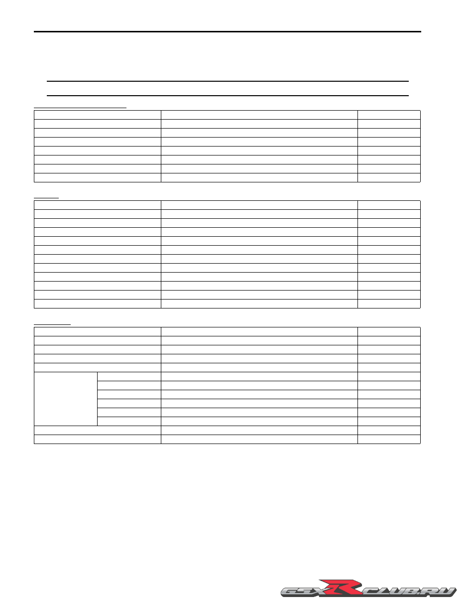
Specifications

Specifications

B947H10107001

NOTE

These specifications are subject to change without notice.


Dimensions and dry mass

Engine

Drive train

Item

Specification

Remark

Overall length

2 045 mm (80.5 in)

Overall width

720 mm (28.3 in)

Overall height

1 130 mm (44.5 in)

Wheelbase

1 405 mm (55.3 in)

Ground clearance

130 mm (5.1 in)

Seat height

810 mm (31.9 in)

Curb mass

205 kg (452 lbs)

Item

Specification

Remark

Type

4-stroke, Liquid-cooled, DOHC

Number of cylinders

4

Bore

74.5 mm (2.933 in)

Stroke

57.3 mm (2.256 in)

Displacement

999 cm

3

 (61.0 cu. in)

Compression ratio

12.8 : 1

Fuel system

Fuel injection system

Air cleaner

Paper element

Starter system

Electric

Lubrication system

Wet sump

Idle speed

1 150 

±

 100 r/min

Item

Specification

Remark

Clutch

Wet multi-plate type

Transmission

6-speed constant mesh

Gearshift pattern

1-down, 5-up

Primary reduction ratio

1.617 (76/47)

Gear ratios

Low

2.562 (41/16)

2nd

2.052 (39/19)

3rd

1.714 (36/21)

4th

1.500 (36/24)

5th

1.360 (34/25)

Top

1.269 (33/26)

Final reduction ratio

2.470 (42/17)

Drive chain

DID50VAZ, 114 links

-------------------------------------------------------------------------------------------------------------------------------------------------------------

General Information:  0A-10

Chassis

Electrical

Capacities

Item

Specification

Remark

Front suspension

Inverted telescopic, coil spring, oil damped

Rear suspension

Link type, coil spring, oil damped

Front suspension stroke

125 mm (4.9 in)

Rear wheel travel

130 mm (5.1 in)

Caster

23

°

 50’

Trail

98 mm (3.86 in)

Steering angle

27

°

 (right & left)

Turning radius

3.4 m (11.2 ft)

Front brake

Disc brake, twin

Rear brake

Disc brake

Front tire size

120/70ZR17M/C (58W), tubeless

Rear tire size

190/50ZR17M/C (73W), tubeless

Item

Specification

Remark

Ignition type

Electronic ignition (Transistorized)

Ignition timing

4

°

 B.T.D.C. at 1 150 r/min

Spark plug

NGK CR9EIA-9 or DENSO IU27D

Battery

12 V 36.0 kC (10 Ah)/10 HR

Generator

Three-phase A.C. generator

Main fuse

30 A

Fuse

30/10/10/15/10/10/15 A

Headlight

High

12 V 65 W (H9)

Low

12 V 55 W (H11)

Position light

12 V 5 W

Brake light/Taillight

LED

License plate light

12 V 5 W

Turn signal light

12 V 21 W

Speedometer light

LED

Tachometer light

LED

Fuel level indicator light

LED

Turn signal indicator light

LED

Neutral indicator light

LED

High beam indicator light

LED

Oil pressure/Coolant temperature 
indicator light

LED

FI indicator light/Sd indicator light

LED

Engine R.P.M. indicator light

LED

Immobilizer indicator light

LED

E-02, 19, 24, 51

Item

Specification

Remark

Fuel tank

16.5 L (4.4/3.6 US/lmp gal)

E-33

17.5 L (4.6/3.8 US/lmp gal)

Others

Engine oil

Oil change

2 800 ml (3.0/2.5 US/lmp qt)

With filter change

3 300 ml (3.5/3.0 US/lmp qt)

Overhaul

3 600 ml (3.8/3.2 US/lmp qt)

Engine coolant

2 750 ml (2.8/2.4 US/lmp qt)

-------------------------------------------------------------------------------------------------------------------------------------------------------------

0A-11 General Information: 

Special Tools and Equipment

Special Tool

B947H10108002

09900–06104

Snap ring remover 
(Open type)

09900–06107

Snap ring remover 
(Open type)

09900–06108

Snap ring remover 
(Close type)

09900–18740

Hexagon socket (24 
mm)

09900–20102

Vernier calipers (200 
mm)

09900–20202

Micrometer (25 – 50 
mm)

09900–20203

Micrometer (50 – 75 
mm)

09900–20205

Micrometer (0 – 25 
mm)

09900–20530

Cylinder gauge set

09900–20602

Dial gauge

09900–20605

Dial calipers (10 – 34 
mm)

09900–20607

Dial gauge

09900–20701

Dial gauge chuck

09900–20803

Thickness gauge

09900–20805

Tire depth gauge

09900–21304

V blocks

09900–22301

Plastigage (0.025 – 
0.076 mm)

09900–22302

Plastigage (0.051 – 
0.152 mm)

09900–22401

Small bore gauge (10 
– 18 mm)

09900–22403

Small bore gauge (18 
– 35 mm)

09900–25008

Multi circuit tester set

09900–25009

Needle-point probe 
set

09904–41010

SUZUKI Diagnostic 
system set

09913–50121

Oil seal remover

09913–70210

Bearing installing set 
(10 – 75 

Φ

)

-------------------------------------------------------------------------------------------------------------------------------------------------------------

General Information:  0A-12

09915–17410

Oil pressure gauge 
adapter

09915–40610

Oil filter wrench

09915–63311

Compression gauge 
attachment

09915–64512

Compression gauge

09915–74521

Adapter hose

09915–77331

Oil pressure gauge 
(1000 kPa)

09916–10911

Valve lapper set

09916–14510

Valve lifter

09916–14522

Valve lifter attachment

09916–33210

Valve guide reamer 
(4.5 mm)

09916–33320

Valve guide reamer 
(9.8 mm)

09916–34542

Reamer handle

09916–43211

Valve guide installer & 
remover

09916–53380

Valve guide installer 
attachment

09916–77310

Piston ring 
compressor

09916–84511

Tweezer

09917–47011

Vacuum pump gauge 
set

09919–28620

Sleeve protector

09920–53740

Clutch sleeve hub 
holder

09921–20210

Bearing remover (12 
mm)

09921–20240

Bearing remover set

09922–22711

Drive chain cutting 
and joint tool set

09923–74511

Bearing remover

09924–84510

Bearing installer set

09924–84521

Bearing installer set

-------------------------------------------------------------------------------------------------------------------------------------------------------------

0A-13 General Information: 

09925–18011

Bearing installer

09930–10121

Spark plug wrench set

09930–11920

Torx bit (JT40H)

09930–11940

Torx bit holder

09930–11950

Torx wrench (5 mm)

09930–11960

Torx wrench (4 mm)

09930–30104

Rotor remover sliding 
shaft

09930–30460

Rotor remover bolt

09930–34970

Rotor remover

09930–40113

Flywheel rotor holder

09930–44530

Rotor holder

09930–73170

Starter torque limiter 
holder

09930–73181

Starter torque limiter 
socket

09930–82720

Mode selection switch

09940–14911

Steering stem nut 
socket wrench

09940–14940

Swingarm pivot thrust 
adjuster wrench

09940–14960

Steering stem nut 
socket wrench

09940–14990

Engine mounting 
adjust wrench

09940–40211

Fuel pressure gauge 
adapter

09940–40220

Fuel pressure gauge 
attachment

09940–52861

Front fork oil seal 
installer set

09940–84710

Rod guide case 
wrench

09940–92720

Spring scale

09941–34513

Bearing installer

09941–53670

Front fork cap socket 
wrench (45 mm)

-------------------------------------------------------------------------------------------------------------------------------------------------------------

General Information:  0A-14

09943–74111

Front fork oil level 
gauge

09943–88211

Pinion bearing installer

09944–28321

Hexagon socket (19 
mm)

99565–01010–020

CD-ROM Ver.20

-------------------------------------------------------------------------------------------------------------------------------------------------------------

0B-1 Maintenance and Lubrication: 

General Information

Maintenance and Lubrication

Precautions

Precautions for Maintenance

B947H10200001

The “Periodic Maintenance Schedule Chart” lists the recommended intervals for all the required periodic service work 
necessary to keep the motorcycle operating at peak performance and economy. Maintenance intervals are expressed 
in terms of kilometers, miles and months for your convenience.

NOTE

More frequent servicing may be required on motorcycles that are used under severe conditions.


General Description

Recommended Fluids and Lubricants

B947H10201001

Refer to “Fuel and Oil Recommendation” in Section 0A (Page 0A-3) and “Engine Coolant Recommendation” in 
Section 0A (Page 0A-4).

-------------------------------------------------------------------------------------------------------------------------------------------------------------

Maintenance and Lubrication:  0B-2

Scheduled Maintenance

Periodic Maintenance Schedule Chart

B947H10205001

NOTE

I = Inspect and clean, adjust, replace or lubricate as necessary.
R = Replace.
T = Tighten.


Item

Interval

km

1 000

6 000

12 000

18 000

24 000

miles

600

4 000

7 500

11 000

14 500

months

2

12

24

36

48

Air cleaner element

I

I

R

I

Exhaust pipe bolts and muffler bolts

T

T

T

Exhaust control valve

I

I

I

Valve  clearance

I

Spark plugs

I

R

I

R

Fuel  line

I

I

I

I

Evaporative emission control system
(E-33 only)

I

I

Engine  oil

R

R

R

R

R

Engine oil filter

R

R

Throttle  cable  play

I

I

I

I

I

PAIR (air supply) system

I

I

Throttle valve synchronization

I

(E-33 only)

I

I

Engine coolant

Replace every 2 years.

Radiator  hose

I

I

I

I

Clutch  cable  play

I

I

I

I

Drive chain

I

I

I

I

I

Clean and lubricate every 1 000 km (600 miles).

Brakes

I

I

I

I

I

Brake fluid

I

I

I

I

Replace every 2 years.

Brake hoses

I

I

I

I

Replace every 4 years.

Tires

I

I

I

I

Steering

I

I

I

Front fork

I

I

Rear suspension

I

I

Chassis  bolts  and  nuts

T

T

T

T

T

-------------------------------------------------------------------------------------------------------------------------------------------------------------

0B-3 Maintenance and Lubrication: 

Lubrication Points

B947H10205002

Proper lubrication is important for smooth operation and long life of each working part of the motorcycle.
Major lubrication points are indicated as follows.

NOTE

• Before lubricating each part, clean off any rusty spots and wipe off any grease, oil, dirt or grime.

• Lubricate exposed parts which are subject to rust, with a rust preventative spray whenever the 

motorcycle has been operated under wet or rainy conditions.


Repair Instructions

Air Cleaner Element Replacement

B947H10206001

Replace air cleaner element
Every 18 000 km (11 000 miles, 36 months)

Refer to “Air Cleaner Element Removal and Installation” 
in Section 1D (Page 1D-6)
.

Air Cleaner Element Inspection

B947H10206002

Inspect air cleaner element
Every 6 000 km (4 000 miles, 12 months) 

Inspection

1) Remove the air cleaner element. Refer to “Air 

Cleaner Element Removal and Installation” in 
Section 1D (Page 1D-6).

2) Inspect the air cleaner element for clogging. If it is 

clogged with dirt, replace it with a new one.

CAUTION

!


Do not blow the air cleaner element with 
compressed air.


NOTE

If driving under dusty conditions, replace the 
air cleaner element more frequently. Make 
sure that the air cleaner is in good condition 
at all times. The life of the engine depends 
largely on this component.


5

6

1

2

3

4

I947H1020033-02

1. Clutch lever holder

5. Brake lever holder

2. Side stand pivot and spring hook

6. Brake pedal pivot and footrest pivot

3. Gearshift lever pivot and footrest pivot

: Apply grease.

4. Drive chain

: Apply oil.

I947H1020001-01

-------------------------------------------------------------------------------------------------------------------------------------------------------------

Maintenance and Lubrication:  0B-4

3) Drain water from the air cleaner box by removing the 

drain plug (1).

4) Reinstall the removed parts.

Exhaust Pipe Bolt and Muffler Bolt Inspection

B947H10206003

Tighten exhaust pipe bolts and muffler bolts
Initially at 1 000 km (600 miles, 2 months) and every 
12 000 km (7 500 miles, 24 months) thereafter

Check the exhaust pipe bolts and muffler bolts to the 
specified torque.

Tightening torque
Exhaust pipe bolt (a):  23 N·m (2.3 kgf-m, 16.5 lbf-ft)
Muffler chamber connecting bolt (b):  30 N·m (3.0 
kgf-m, 21.5 lbf-ft)
Muffler chamber bracket bolt (c):  25 N·m (2.5 kgf-m, 
18.0 lbf-ft)
Muffler chamber mounting bolt (d):  23 N·m (2.3 kgf-
m, 16.5 lbf-ft)
Muffler connecting bolt (e):  23 N·m (2.3 kgf-m, 16.5 
lbf-ft)
Muffler mounting bolt (f):  25 N·m (2.5 kgf-m, 18.0 
lbf-ft)

Exhaust Control Valve Inspection

B947H10206004

Inspect exhaust control valve
Initially at 1 000 km (600 miles, 2 months) and every 
12 000 km (7 500 miles, 24 months) thereafter

Inspect exhaust control valve as follows:

1) Remove the left side cowling. Refer to “Exterior 

Parts Removal and Installation” in Section 9D 
(Page 9D-6)
.

2) Check the exhaust control valve actuator (1) for its 

smooth movement when the ignition switch is turned 
on. If the exhaust valve actuator does not move 
smoothly, check exhaust valve actuator electrical 
circuit. Refer to “EXCVA Inspection” in Section 1K 
(Page 1K-9).

3) Check the lock-nuts (2) for tightness. If the lock-nuts 

(2) are loose, tighten them after adjusting the cable 
length. Refer to “EXCV Cable Removal and 
Installation” in Section 1K (Page 1K-6).

1

I947H1020002-01

FWD

FWD

(f)

(e)

(e)

(d)

(c)

(b)

(a)

I947H1020053-01

1

I947H1020003-02

2

I947H1020004-01

-------------------------------------------------------------------------------------------------------------------------------------------------------------

0B-5 Maintenance and Lubrication: 

Valve Clearance Inspection and Adjustment

B947H10206005

Inspect valve clearance
Initially every 24 000 km (14 500 miles, 48 months)

Inspection

Valve clearance adjustment must be checked and 
adjusted, a) at the time of periodic inspection, b) when 
the valve mechanism is serviced, and c) when the 
camshafts are removed for servicing.

1) Lift and support the fuel tank. Refer to “Fuel Tank 

Removal and Installation” in Section 1G (Page 1G-
9).

2) Remove the air cleaner box. Refer to “Air Cleaner 

Box Removal and Installation” in Section 1D 
(Page 1D-7).

3) Remove the cylinder head cover. Refer to “Engine 

Top Side Disassembly” in Section 1D (Page 1D-26).

4) Remove the spark plugs. Refer to “Ignition Coil and 

Spark Plug Removal and Installation” in Section 1H 
(Page 1H-6).

Valve clearance (When cold)
IN: 0.08 – 0.18 mm (0.003 – 0.007 in)
EX: 0.18 – 0.28 mm (0.007 – 0.011 in)

5) Remove the valve timing inspection cap (1).

NOTE

• The cam must be at positions, “A” or “B”, 

when checking the valve clearance. 
Clearance readings should not be taken 
with the cam in any other position than 
these two positions.

• The valve clearance should be taken when 

each cylinder is at Top Dead Center (TDC) 
of compression stroke.

• The clearance specification is for COLD 

state.

• To turn the crankshaft for valve clearance 

checking, be sure to use a wrench, and 
rotate in the normal running direction.


6) Turn the crankshaft to bring the line “C” on the CKP 

sensor rotor to the slit “D” of cap hole thread and 
also to bring the notches “E” on the left ends of both 
camshafts (EX and IN) to the positions as shown.

1

I947H1020005-01

“A”

“B”

“A”

“B”

EX

IN

I823H1020007-01

“C”

“D”

I947H1020006-02

FWD

“E”

I947H1020036-01

-------------------------------------------------------------------------------------------------------------------------------------------------------------

Maintenance and Lubrication:  0B-6

7) In this condition, read the valve clearance at the 

valves “F” (IN and EX of No. 4 cylinder, EX of No. 3 
and IN of No. 2). If the clearance is out of 
specification, adjust the clearance.

Special tool

:  09900–20803 (Thickness gauge)

8) Turn the crankshaft 360

°

 degrees (one rotation) to 

bring the line on the CKP sensor rotor to the rib 
behind the clutch cover and also to bring the notches 
“E” to the position as shown.

9) Read the clearance at the rest of the valves “G” and 

adjust the clearance if necessary.

Adjustment

The clearance is adjusted by replacing the existing 
tappet shim with a thicker or thinner shim.

1) Remove the intake or exhaust camshaft. Refer to 

“Engine Top Side Disassembly” in Section 1D 
(Page 1D-26).

2) Remove the tappet (1) and shim (2) by fingers or 

magnetic hand.

3) Check the figures printed on the shim. These figures 

indicate the thickness of the shim, as illustrated.

4) Select a replacement shim that will provide a 

clearance within the specified range. For the 
purpose of this adjustment, a total of 21 sizes of 
tappet shim are available ranging from 1.20 to 2.20 
mm in steps of 0.05 mm. 

5) Fit the selected shim (2) to the valve stem end, with 

numbers toward tappet. Be sure to check shim size 
with micrometer to ensure its size.

NOTE

• Be sure to apply engine oil to tappet shim 

top and bottom faces.

• When seating the tappet shim, be sure the 

figure printed surface faces the tappet.


FWD

“F”

“F”

“F”

“F”

I947H1020050-01

FWD

“E”

I947H1020037-01

FWD

“G”

“G”

“G”

“G”

I947H1020051-01

“F”

“G”

Exhaust camshaft

Intake camshaft

FWD

FWD

FWD

FWD

Notch “E” position

Cam

position

I837H1020013-01

2

1

I947H1020034-01

1.70 mm

I837H1020014-01

2

I947H1020007-02

-------------------------------------------------------------------------------------------------------------------------------------------------------------

0B-7 Maintenance and Lubrication: 

(INTAKE SIDE)

MEASURED 

VA

LV

E


CLEARANCE 

(mm)

SUFFIX

NO.

120

125

130

135

140

145

150

155

160

165

170

175

180

185

190

195

200

205

210

215

220

PRESENT

SHIM SIZE

(mm)

1.20

1.25

1.30

1.35

1.40

1.45

1.50

1.55

1.60

1.65

1.70

1.75

1.80

1.85

1.90

1.95

2.00

2.05

2.10

2.15

2.20

0.00 – 0.02

1.20

1.25

1.30

1.35

1.40

1.45

1.50

1.55

1.60

1.65

1.70

1.75

1.80

1.85

1.90

1.95

2.00

2.05

2.10

0.03 – 0.07

1.20

1.25

1.30

1.35

1.40

1.45

1.50

1.55

1.60

1.65

1.70

1.75

1.80

1.85

1.90

1.95

2.00

2.05

2.10

2.15

0.08 – 0.18

SPECIFIED CLEARANCE/NO 

ADJUSTMENT

 REQUIRED

0.19 – 0.28

1.30

1.35

1.40

1.45

1.50

1.55

1.60

1.65

1.70

1.75

1.80

1.85

1.90

1.95

2.00

2.05

2.10

2.15

2.20

2.20

0.29 – 0.33

1.35

1.40

1.45

1.50

1.55

1.60

1.65

1.70

1.75

1.80

1.85

1.90

1.95

2.00

2.05

2.10

2.15

2.20

0.34 – 0.38

1.40

1.45

1.50

1.55

1.60

1.65

1.70

1.75

1.80

1.85

1.90

1.95

2.00

2.05

2.10

2.15

2.20

0.39 – 0.43

1.45

1.50

1.55

1.60

1.65

1.70

1.75

1.80

1.85

1.90

1.95

2.00

2.05

2.10

2.15

2.20

0.44 – 0.48

1.50

1.55

1.60

1.65

1.70

1.75

1.80

1.85

1.90

1.95

2.00

2.05

2.10

2.15

2.20

0.49 – 0.53

1.55

1.60

1.65

1.70

1.75

1.80

1.85

1.90

1.95

2.00

2.05

2.10

2.15

2.20

0.54 – 0.58

1.60

1.65

1.70

1.75

1.80

1.85

1.90

1.95

2.00

2.05

2.10

2.15

2.20

0.59 – 0.63

1.65

1.70

1.75

1.80

1.85

1.90

1.95

2.00

2.05

2.10

2.15

2.20

0.64 – 0.68

1.70

1.75

1.80

1.85

1.90

1.95

2.00

2.05

2.10

2.15

2.20

0.69 – 0.73

1.75

1.80

1.85

1.90

1.95

2.00

2.05

2.10

2.15

2.20

0.74 – 0.78

1.80

1.85

1.90

1.95

2.00

2.05

2.10

2.15

2.20

0.79 – 0.83

1.85

1.90

1.95

2.00

2.05

2.10

2.15

2.20

0.84 – 0.88

1.90

1.95

2.00

2.05

2.10

2.15

2.20

0.89 – 0.93

1.95

2.00

2.05

2.10

2.15

2.20

0.94 – 0.98

2.00

2.05

2.10

2.15

2.20

0.99 – 1.03

2.05

2.10

2.15

2.20

1.04 – 1.08

2.10

2.15

2.20

1.09 – 1.13

2.15

2.20

1.14 – 1.18

2.20

T

APPET

 SHIM SET

 (12800-05830)

HOW 

T

O USE 

THIS CHAR

T

:

I. 

Measure valve clearance. “ENGINE IS COLD”

II. 

Measure present shim size.

III. 

Match clearance in vertical column with present shim size in horizontal

 column.

 EXAMPLE


V

alve clearance is 

0.23 mm


Present shim size 

1.70 mm


Shim size to be used 

1.80 mm

T

APPET

 SHIM SELECTION 

T

ABLE [INT

AKE]

T

APPET

 SHIM NO. (12892-05C00-XXX)

I837H1020015-02

-------------------------------------------------------------------------------------------------------------------------------------------------------------

Maintenance and Lubrication:  0B-8

(EXHAUST SIDE)

HOW 

T

O USE 

THIS CHAR

T

:

I. 

Measure valve clearance. “ENGINE IS COLD”

II. 

Measure present shim size.

III. 

Match clearance in vertical column with present shim size in horizontal

 column.

 EXAMPLE


V

alve clearance is 

0.33 mm


Present shim size 

1.70 mm


Shim size to be used 

1.80 mm

T

APPET

 SHIM SELECTION 

T

ABLE [EXHAUST]

T

APPET

 SHIM NO. (12892-05C00-XXX)

MEASURED 

VA

LV

E

CLEARANCE 

(mm)

SUFFIX

NO.

120

125

130

135

140

145

150

155

160

165

170

175

180

185

190

195

200

205

210

215

220

PRESENT

SHIM SIZE

(mm)

1.20

1.25

1.30

1.35

1.40

1.45

1.50

1.55

1.60

1.65

1.70

1.75

1.80

1.85

1.90

1.95

2.00

2.05

2.10

2.15

2.20

1.20

1.25

1.30

1.35

1.40

1.45

1.50

1.55

1.60

1.65

1.70

1.75

1.80

1.85

1.90

1.95

2.00

2.05

1.20

1.25

1.30

1.35

1.40

1.45

1.50

1.55

1.60

1.65

1.70

1.75

1.80

1.85

1.90

1.95

2.00

2.05

2.10

0.08 – 0.12

SPECIFIED CLEARANCE/NO 

ADJUSTMENT

 REQUIRED

0.13 – 0.17

1.30

1.35

1.40

1.45

1.50

1.55

1.60

1.65

1.70

1.75

1.80

1.85

1.90

1.95

2.00

2.05

2.10

2.15

2.20

2.20

0.18 – 0.28

1.35

1.40

1.45

1.50

1.55

1.60

1.65

1.70

1.75

1.80

1.85

1.90

1.95

2.00

2.05

2.10

2.15

2.20

0.29 – 0.38

1.40

1.45

1.50

1.55

1.60

1.65

1.70

1.75

1.80

1.85

1.90

1.95

2.00

2.05

2.10

2.15

2.20

0.39 – 0.43

1.45

1.50

1.55

1.60

1.65

1.70

1.75

1.80

1.85

1.90

1.95

2.00

2.05

2.10

2.15

2.20

0.44 – 0.48

1.50

1.55

1.60

1.65

1.70

1.75

1.80

1.85

1.90

1.95

2.00

2.05

2.10

2.15

2.20

0.49 – 0.53

1.55

1.60

1.65

1.70

1.75

1.80

1.85

1.90

1.95

2.00

2.05

2.10

2.15

2.20

0.54 – 0.58

1.60

1.65

1.70

1.75

1.80

1.85

1.90

1.95

2.00

2.05

2.10

2.15

2.20

0.59 – 0.63

1.65

1.70

1.75

1.80

1.85

1.90

1.95

2.00

2.05

2.10

2.15

2.20

0.64 – 0.68

1.70

1.75

1.80

1.85

1.90

1.95

2.00

2.05

2.10

2.15

2.20

0.69 – 0.73

1.75

1.80

1.85

1.90

1.95

2.00

2.05

2.10

2.15

2.20

0.74 – 0.78

1.80

1.85

1.90

1.95

2.00

2.05

2.10

2.15

2.20

0.79 – 0.83

1.85

1.90

1.95

2.00

2.05

2.10

2.15

2.20

0.84 – 0.88

1.90

1.95

2.00

2.05

2.10

2.15

2.20

0.89 – 0.93

1.95

2.00

2.05

2.10

2.15

2.20

0.94 – 0.98

2.00

2.05

2.10

2.15

2.20

0.99 – 1.03

2.05

2.10

2.15

2.20

1.04 – 1.08

2.10

2.15

2.20

1.09 – 1.13

2.15

2.20

1.14 – 1.18

1.19 – 1.23

1.24 – 1.28

2.20

0.03 – 0.07

1.20

1.25

1.30

1.35

1.40

1.45

1.50

1.55

1.60

1.65

1.70

1.75

1.80

1.85

1.90

1.95

2.00

2.05

2.10

2.15

T

APPET

 SHIM SET

 (12800-05830)

I837H1020016-02

-------------------------------------------------------------------------------------------------------------------------------------------------------------

0B-9 Maintenance and Lubrication: 

6) Install the camshafts and cam chain tension adjuster. 

Refer to “Engine Top Side Assembly” in Section 1D 
(Page 1D-28).

7) Rotate the engine so that the tappet is depressed 

fully. This will squeeze out oil trapped between the 
shim and the tappet that could cause an incorrect 
measurement, then check the clearance again to 
confirm that it is within the specified range.

8) After finishing the tappet clearance adjustment, 

reinstall the removed parts. Refer to “Engine Top 
Side Assembly” in Section 1D (Page 1D-28)
.

Spark Plug Replacement

B947H10206006

Replace spark plug
Every 12 000 km (7 500 miles, 24 months)

Refer to “Ignition Coil and Spark Plug Removal and 
Installation” in Section 1H (Page 1H-6).

Spark Plug Inspection and Cleaning

B947H10206007

Inspect spark plug
Every 6 000 km (4 000 miles, 12 months)

Heat Range

1) Remove the spark plugs. Refer to “Ignition Coil and 

Spark Plug Removal and Installation” in Section 1H 
(Page 1H-6).

2) Check spark plug heat range by observing electrode 

color. If the electrode of the spark plug is wet 
appearing or dark color, replace the spark plug with 
hotter type one. If it is white or glazed appearing, 
replace the spark plug with colder type one.

Heat range

3) After finishing the spark plug inspection, reinstall the 

removed parts.

Tightening torque
Spark plug:  11 N·m (1.1 kgf-m, 8.0 lbf-ft)

Spark Plug Gap

1) Remove the spark plugs. Refer to “Ignition Coil and 

Spark Plug Removal and Installation” in Section 1H 
(Page 1H-6).

2) Measure the spark plug gap using a wire gauge. If it 

is not within the specification, replace the spark plug. 

CAUTION

!


• To prevent the damage of iridium center 

electrode, use a wire gauge to check the 
gap.

• Never adjust the spark plug gap.


Spark plug gap
0.8 – 0.9 mm (0.031 – 0.035 in)

3) After finishing the spark plug inspection, reinstall the 

removed parts.

Tightening torque
Spark plug:  11 N·m (1.1 kgf-m, 8.0 lbf-ft)

Electrodes Condition

1) Remove the spark plugs. Refer to “Ignition Coil and 

Spark Plug Removal and Installation” in Section 1H 
(Page 1H-6)
.

2) Check the worn or burnt condition of the electrodes.

If it is extremely worn or burnt, replace the spark 
plug. And also replace the spark plug if it has a 
broken insulator, or damaged thread.

CAUTION

!


Confirm the thread size and reach when 
replacing the plug. If the reach is too short, 
carbon will be deposited on the screw 
portion of the plug hole and engine damage 
may result.


3) After finishing the spark plug inspection, reinstall the 

removed parts.

Tightening torque
Spark plug:  11 N·m (1.1 kgf-m, 8.0 lbf-ft)

Hot type

Standard

Cold type

NGK

CR8EIA-9

CR9EIA-9

CR10EIA-9

ND

IU24D

IU27D

IU31D

I823H1020005-01

-------------------------------------------------------------------------------------------------------------------------------------------------------------

Maintenance and Lubrication:  0B-10

Fuel Line Inspection

B947H10206008

Inspect fuel line
Every 6 000 km (4 000 miles, 12 months)

Inspect the fuel line in the following procedures:

1) Lift and support the fuel tank. Refer to “Fuel Tank 

Removal and Installation” in Section 1G (Page 1G-
9)
.

2) Inspect the fuel feed hose (1) for damage and fuel 

leakage. If any defects are found, the fuel feed hose 
must be replaced.

WARNING

!


When disconnecting the fuel feed hose from 
E-33 model, drain fuel from the fuel tank first 
to prevent fuel leakage.


3) After finishing the fuel feed hose inspection, reinstall 

the removed parts.

Evaporative Emission Control System 
Inspection (E-33 only)

B947H10206009

Inspect evaporative emission control system
Every 12 000 km (7 500 miles, 24 months)

Inspect the evaporative emission control system 
periodically (E-33 only). Refer to “Evaporative Emission 
Control System Inspection (Only for E-33)” in Section 1B 
(Page 1B-14).

Engine Oil and Filter Replacement

B947H10206010

Replace engine oil
Initially at 1 000 km (600 miles, 2 months) and every 
6 000 km (4 000 miles, 12 months) thereafter

Replace oil filter
Initially at 1 000 km (600 miles, 2 months) and every 
18 000 km (11 000 miles, 36 months) thereafter

Oil should be changed while the engine is warm. Oil filter 
replacement at the above intervals, should be done 
together with the engine oil change.

Engine Oil Replacement

1) Place the motorcycle on the side-stand.

2) Place an oil pan below the engine, and drain engine 

oil by removing the oil drain plug (1) and filler cap 
(2).

3) Tighten the oil drain plug (1) to the specified torque.

CAUTION

!


Replace the gasket washer with a new one.


Tightening torque
Oil drain plug (a):  23 N·m (2.3 kgf-m, 16.5 lbf-ft)

4) Pour new oil through the oil filler. When performing 

an oil change (without oil filter replacement), the 
engine will hold about 2.8 L (3.0/2.5 US/lmp qt) of oil. 
Use of SF/SG or SH/SJ in API with MA in JASO.

5) Start up the engine and allow it to run for several 

minutes at idling speed.

6) Turn off the engine and wait about three minutes.

1

I947H1020008-01

1

I947H1020009-01

2

I947H1020010-01

(a)

1

I947H1020011-01

-------------------------------------------------------------------------------------------------------------------------------------------------------------


Content      ..      1      2      3      ..