SINUMERIK 840D sl. Basesoftware and operating software. Manual (2019) - page 7

Technologies and cycles
18.7 Swiveling
MD32010 $MA_JOG_VELO_RAPID[AX]
Rapid traverse in JOG
AX = axis name
Rotary and machine axes that should trav-
el for swiveling in JOG.
= 10000
Rapid traverse in JOG mode for swiveling in JOG
SD42980 $SC_TOFRAME_MODE
Setting, frame definition for TOROT, PA-
ROT
= 2000
Swivel (default value)
SD42974 $SC_TOCARR_FINE_CORRECTION
Fine offset TCARR (swivel data set)
= 0
No fine offset of the swivel data set vectors.
= 1
Fine offset of the swivel data set vectors.
The parameters of the swivel data set from $TC_CARR41[n] n…number of the swivel data
set and higher apply.
Swiveling in the JOG mode
Cycle alarms 62186 and 62187 can be hidden or displayed using the following cycle machine
data:
MD55410 $MC_MILL_SWIVEL_ALARM_MASK
Activate fault evaluation CYCLE800
Bit 0
Activates fault 61186
= 0
Hide fault 61186 "Active work offset G%4 and base (base reference) contains rotations"
(default setting).
= 1
Display fault 61186
Bit 1
Activate fault 61187
= 0
Hide fault 61187 "Active base and base reference (G500) contain rotations" (default set-
ting).
= 1
Display fault 61187
18.7.2
CYCLE800 checklist for the identification of the machine kinematics
Note
Identification of the machine kinematics according to DIN 66217 or ISO 841-2001
This checklist does not claim to be complete.
● Do the 3 linear axes of the machine that are active for the transformation form an orthogonal
coordinate system? Geometry axes XYZ
● How many swivel kinematics does the machine have?
Combinations of two (or one) rotary axis and the three linear axes are always formed.
SINUMERIK Operate
416
Commissioning Manual, 12/2019, 6FC5397-1DP40-6BA3
Technologies and cycles
18.7 Swiveling
● Which machine components are concerned?
Swivel head, swivel table or swivel head and rotary table.
● What are the names of the rotary axes of the kinematics?
Manual rotary axes are permitted and do not have to be declared in the NC.
● What is the 1st or 2nd d rotary axis of a swivel data set?
Rule: Rotary axis 2 is based on rotary axis 1. With mixed kinematics, rotary axis 1 is always
the axis for the tool orientation.
● Is the traversing direction of the linear axes and the rotary axes correct? Right-hand rule
Rule: If the linear axis or the rotary axis moves the workpiece, the direction of motion of the
axis and also the sign of the rotary axis vector change.
● What is the initial setting of the kinematics?
This defines the tool orientation and the plane G17, G18, G19.
● Which rotary axis rotates around which axis of the coordinate system or the machine axis
(axes)?
This defines the rotary axis vectors of the kinematics.
Example 1:
Head kinematics. Rotary axis 2 rotates around axis Y → rotary axis vector V2xyz = 0,1,0
Example 2:
Table kinematics. Rotary axis 1 rotates around axis X → rotary axis vector V1xyz = -1,0,0
18.7.3
Commissioning swivel data (machine kinematics)
Defining a swivel data set
You must create a swivel data set for every swivel head, swivel table or each combination of
both.
Swivel data sets can be declared in several channels.
A swivel data set comprises the parameters $TC_CARR1[n] to $TC_CARR65[n]
n = number of the swivel data set.
The parameters of the swivel data set ($TC_CARR1[n] to $TC_CARR65[n]) can be read-in and
read-out in the startup operating area. Programming with appropriate value assignment is also
possible in an NC program (manufacturer cycle). The parameters of the swivel data set are
immediately effective after the program has started.
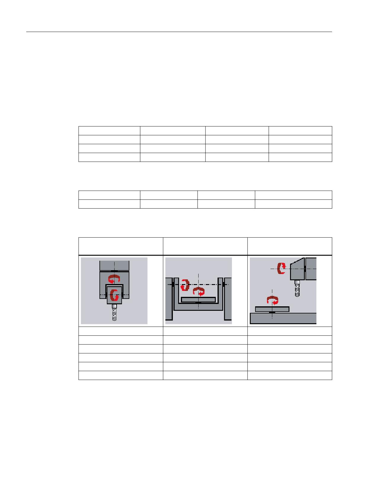
The following softkeys are assigned to the Swivel function in the "Program" → "Various"
operating area:
Milling technology
Turning technology
"Swivel plane"
"Swivel plane"
"Advance milling tool"
"Swivel tool"
→ "Align turning tool"
→ "Align milling tool"
→ "Advance milling tool"
The "Align turning tool" and "Align milling tool" softkeys are only displayed if the "B-axis
kinematics" function has been activated via $TC_CARR37[n].
SINUMERIK Operate
Commissioning Manual, 12/2019, 6FC5397-1DP40-6BA3
417
Technologies and cycles
18.7 Swiveling
Offset vectors I1 to I4
The vectors always contain three components, which are the reference to the machine axes (X,
Y, Z). The positions in the kinematic chain are measured by the machine manufacturer; they are
always relevant with respect to a swivel head / swivel table (swivel data set). Offset vectors I1
to I4 refer to the non-swiveled state of the rotary axes (machine kinematics basic setting).
The machine kinematics used do not need to be fully implemented. However, be aware that the
traversing range in the swivel planes may be restricted. If machine kinematics are to be
implemented with just one rotary axis, this must always be declared as the 1st rotary axis.
$TC_CARR1[n],
$TC_CARR2[n],
$TC_CARR3[n]
Offset vector I1xyz
$TC_CARR4[n],
$TC_CARR5[n],
$TC_CARR6[n]
Offset vector I2xyz
$TC_CARR15[n],
$TC_CARR16[n],
$TC_CARR17[n]
Offset vector I3xyz
$TC_CARR18[n],
$TC_CARR19[n],
$TC_CARR20[n]
Offset vector I4xyz
Rotary axis vectors V1 and V2
$TC_CARR7[n],
$TC_CARR8[n],
$TC_CARR9[n]
Rotary axis vector V1xyz
$TC_CARR10[n],
$TC_CARR11[n],
$TC_CARR12[n]
Rotary axis vector V2xyz
Kinematic types $TC_CARR23[n]
Swivel head (type T)
Swivel table (type P)
Swivel head +
Swivel table (type M)
Offset vector I1
Offset vector I2
Offset vector I1
Rotary axis vector V1
Rotary axis vector V1
Rotary axis vector V1
Offset vector I2
Offset vector I3
Offset vector I2
Rotary axis vector V2
Rotary axis vector V2
Offset vector I3
Offset vector I3
Offset vector I4
Rotary axis vector V2
Offset vector I4
Further information
Further information on tool offsets or on multiple transformations can be found in:
● Function Manual Tools
● Function Manual Transformations
SINUMERIK Operate
418
Commissioning Manual, 12/2019, 6FC5397-1DP40-6BA3
Technologies and cycles
18.7 Swiveling
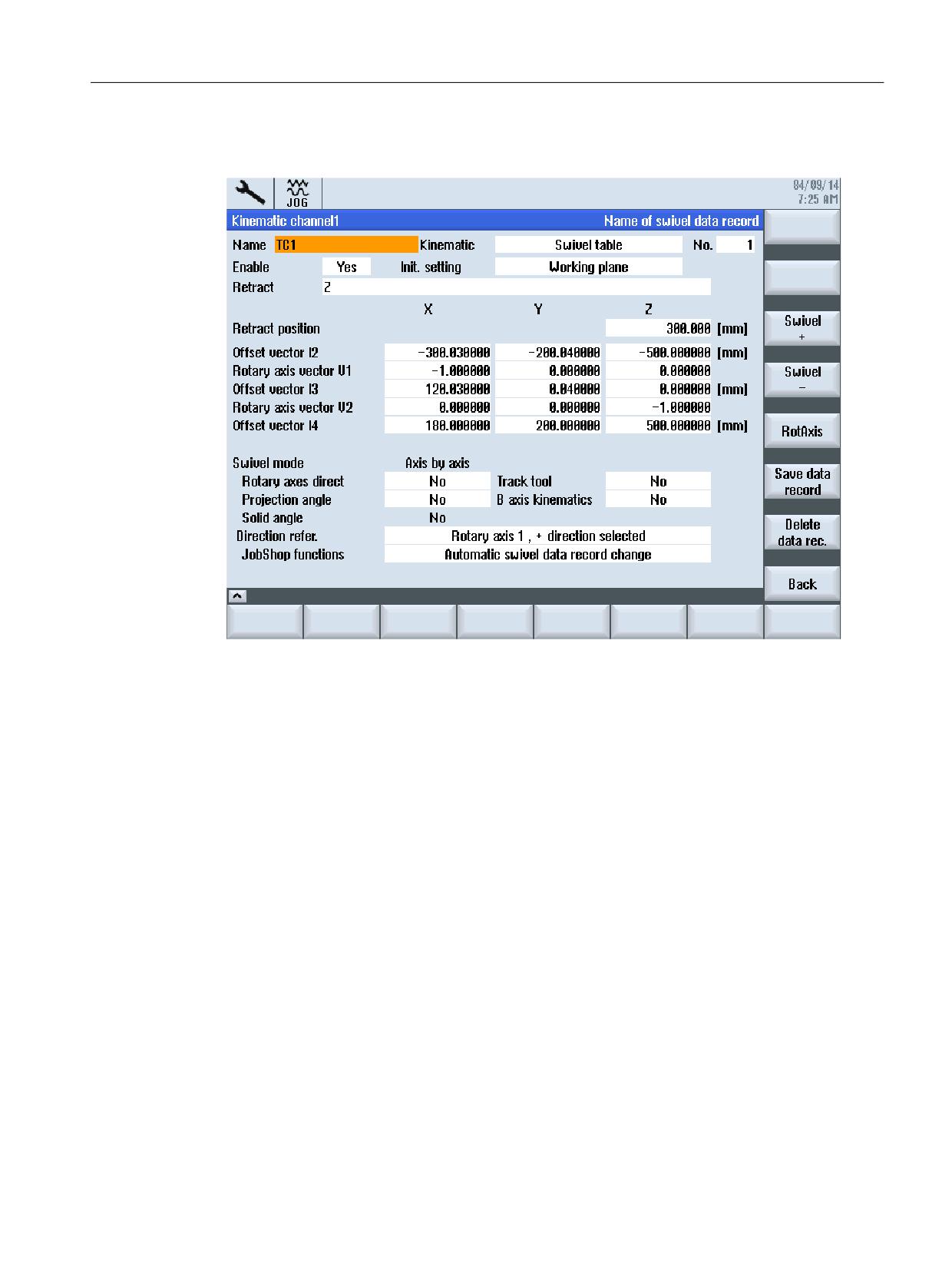
Name of the swivel data set
Figure 18-4
Dialog to input parameters for the swivel data set
If multiple swivel data sets are declared in each NC channel, a name is assigned to each swivel
data set: $TC_CARR34[n]
No name needs to be specified if the swivel-mounted tool holder is not exchangeable (i.e. one
swivel data set per channel).
The name of the swivel data set may only contain characters that are permissible for NC
programming: A...Z, 0...9 and _ !
If multiple NC channels have been set up, note the settings in MD28085. If a TO unit is assigned
to multiple NC channels, the channel display in the dialog corresponds to the TO unit.
Further information: SINUMERIK Operate Commissioning Manual, Chapter "Technological
cycles for swiveling (Page 407)"
Offset vectors I1 to I4 $TC_CARR1[n] ... $TC_CARR20[n]
The vectors always contain three components, which are the reference to the machine axes (X,
Y, Z). The positions in the kinematic chain are measured by the machine manufacturer; they are
always relevant with respect to a swivel head/swivel table (swivel data record).
Offset vectors I1 to I4 refer to the non-swiveled state of the rotary axes (basic setting: machine
kinematics). However, be aware that the traversing range in the swivel planes may be
restricted. If machine kinematics are to be implemented with just one rotary axis, this must
always be declared as the 1st rotary axis.
SINUMERIK Operate
Commissioning Manual, 12/2019, 6FC5397-1DP40-6BA3
419
Technologies and cycles
18.7 Swiveling
Manually adjustable rotary axes (manual mode) are possible with and without measuring
systems and can be used with "simple machines".
Rotary axes that are positioned by an additional mechanical system, can be declared in the
"Semiautomatic" mode.
Example
In a boring mill, the swivel head is positioned by coupling the spindle. In this case, the rotary
axes of the swivel head must be declared as "Semiautomatic". The appropriate machine-
specific cycles are called in CUST_800.SPF.
Machine manufacturer
Follow the machine manufacturer's instructions.
Swivel head
● I3 distance from the tool adapter to the pivot point/intersection of the 2nd rotary axis
● I2 distance from the pivot point/intersection of the 2nd rotary axis to the pivot point/
intersection of the 1st rotary axis
● I1 closure of the I1=-(I2+I3) vector chain, if the swivel head cannot be changed
Swivel table
● I2 distance from the machine reference point to the pivot point/intersection of the 1st rotary
axis
● I3 distance from the pivot point/intersection of the 1st rotary axis to the pivot point/
intersection of the 2nd rotary axis (or to the reference point of the tool adapter)
● I4 closure of the I4=-(I2+I3) vector chain, if the swivel table cannot be changed
Swivel head/swivel table (mixed kinematics)
● I2 distance from the tool adapter to the pivot point/intersection of the 1st rotary axis
● I1 closure of the I1=-I2 vector chain, if the swivel head cannot be changed
● I3 distance from the machine reference point to the pivot point/intersection of the 2nd rotary
axis (or to the reference point of the tool adapter)
● I4 closure of the I4=-I3 vector chain, if the swivel table cannot be changed
The offset vectors do not have to point to the pivot point of the rotary axes. The important thing
is that they point to a point on the direction of rotation (intersection).
The sign of the offset vectors (I1 to I4) and the rotary axis vectors (V1, V2) result from the
specifications of the axis directions according to ISO 841-2001 or DIN 66217 (right-hand rule).
SINUMERIK Operate
420
Commissioning Manual, 12/2019, 6FC5397-1DP40-6BA3
Technologies and cycles
18.7 Swiveling
In the case of machine kinematics that move the workpiece (rotary table), the axis direction is
reversed.
Note
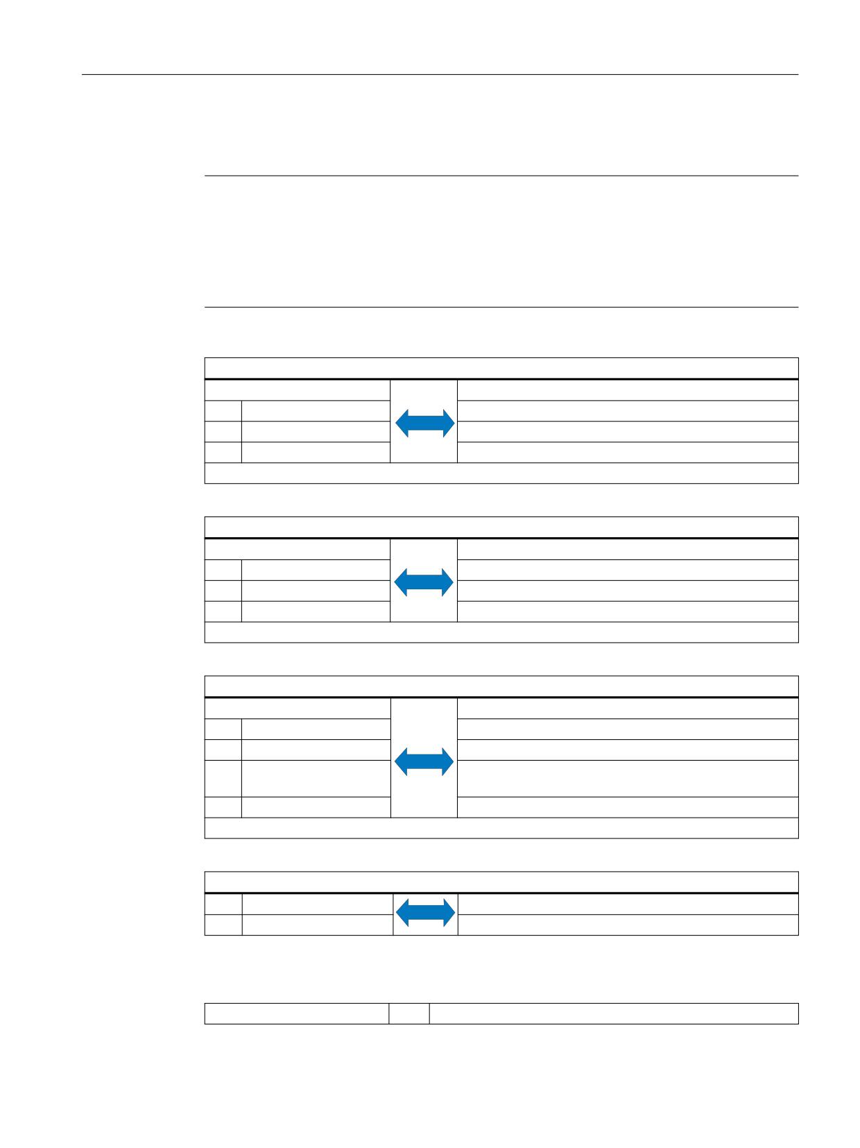
Interrelation of TOOLCARRIER ⇔ 5-axis transformation (transformer type 24, 40, 56):
For 5-axis transformation, transformer type 72 in MD24100: $MC_TRAFO_TYPE_1 can be
used.
In the case of transformer type 72, the vectors of the TOOLCARRIER in MD24582:
$MC_TRAFO5_TCARR_NO_1 are used.
Swivel head (swivel-mounted tool)
$TC_CARR23[n]="T"
MD24100: $MC_TRAFO_TYPE_1=24
I1
$TC_CARR1...3[n]
MD24500: $MC_TRAFO5_PART_OFFSET_1 [0...2]
I2
$TC_CARR4...6[n]
MD24560: $MC_TRAFO5_JOINT_OFFSET_1 [0...2]
I3
$TC_CARR15...17[n]
MD24550: $MC_TRAFO5_BASE_TOOL_1 [0...2]
Closure of the I1=-(I2+I3) vector chain; for fixed-mounted machine kinematics
Swivel table (swivel-mounted workpiece)
$TC_CARR23[n]="P"
MD24100: $MC_TRAFO_TYPE_1=40
I2
$TC_CARR4...6[n]
MD24550: $MC_TRAFO5_BASE_TOOL_1 [0..2]
I3
$TC_CARR15...17[n]
MD24558: $MC_TRAFO5_JOINT_OFFSET_1 [0...2]
I4
$TC_CARR18...20[n]
MD24500: $MC_TRAFO5_PART_OFFSET_1 [0...2]
Closure of the I4=-(I2+I3) vector chain; for fixed-mounted machine kinematics
Swivel head + swivel table (swivel-mounted tool + workpiece)
$TC_CARR23[n]="M"
MD24100: $MC_TRAFO_TYPE_1=56
I1
$TC_CARR1...3[n]
MD24560: $MC_TRAFO5_JOINT_OFFSET_1 [0...2]
I2
$TC_CARR4...6[n]
MD24550: $MC_TRAFO5_BASE_TOOL_1 [0...2]
I3
$TC_CARR15...17[n]
MD24558: $MC_TRAFO5_JOINT_OFF-
SET_PART_1[0...2]
I4
$TC_CARR18...20[n]
MD24500: $MC_TRAFO5_PART_OFFSET_1 [0...2]
Closure of the I1=-I2 I4=-I3 vector chain; for fixed-mounted machine kinematics
Rotary axis vectors V1, V2
V1
$TC_CARR7..9[n]
MD24570: $MC_TRAFO5_AXIS1_1[0..2]
V2
$TC_CARR10..12[n]
MD24572: $MC_TRAFO5_AXIS2_1[0..2]
Fine offsets of offset vectors
$TC_CARR41[n]
to
$TC_CARR60[n]
SINUMERIK Operate
Commissioning Manual, 12/2019, 6FC5397-1DP40-6BA3
421
Technologies and cycles
18.7 Swiveling
Assignment of base vectors to the fine offset vectors:
I1 $TC_CARR1..3[n]
to
$TC_CARR41..43[n]
I2 $TC_CARR4..6[n]
to
$TC_CARR44..46[n]
I3 $TC_CARR15..17[n]
to
$TC_CARR55..57[n]
I4 $TC_CARR18..20[n]
to
$TC_CARR58..60[n]
The fine offsets are activated by the following setting data:
SD42974 $SC_TOCARR_FINE_CORREC-
Fine offset TCARR on/off
TION = 1
= 0
When activating a tool holder that can be oriented, the fine offset values are not taken into
account.
= 1
When activating a tool holder that can be oriented, the fine offset values are taken into
account.
The fine offsets act in addition to the corresponding base vectors when the Swivel function
CYCLE800 or the NC function TCARR=n is called.
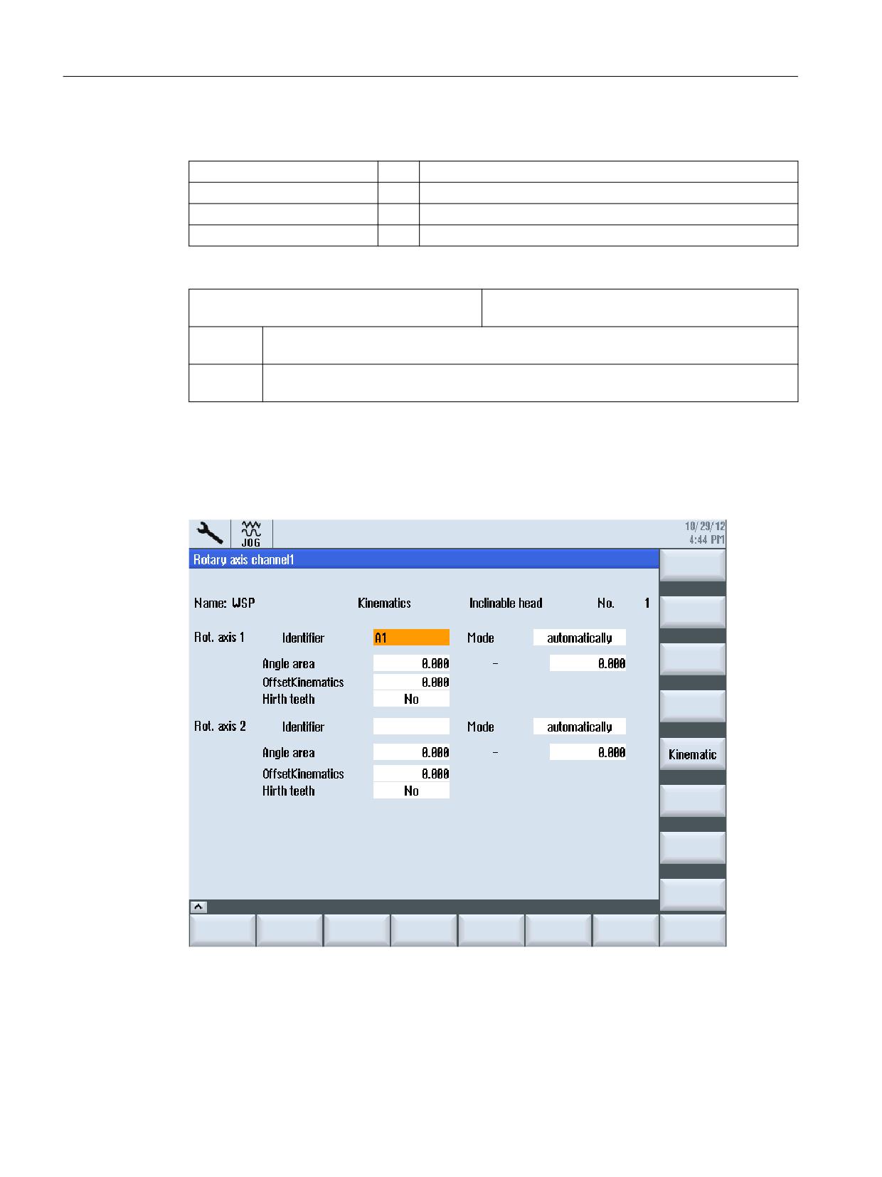
Name of rotary axes
Figure 18-5
Dialog to input parameters for the rotary axis
SINUMERIK Operate
422
Commissioning Manual, 12/2019, 6FC5397-1DP40-6BA3
Technologies and cycles
18.7 Swiveling
The following identifiers should be preferably chosen for the names of the rotary axes:
● Rotary axis rotates around machine axis X → A
● Rotary axis rotates around machine axis X → B
● Rotary axis rotates around machine axis Z → C
For automatic rotary axes, the channel names of the corresponding NC rotary axes must be
entered (see $TC_CARR37[n] TENS and HUNDREDS position: Automatic mode). For manual
(manually adjustable) and semiautomatic rotary axes, you can use any axis identifier (up to six
letters or digits).
Manual and semiautomatic rotary axes are not defined in the NC. With manual rotary axes, the
value for the angular range is entered in the dialog box. Semiautomatic rotary axes are moved
mechanically on the machine, e.g. through a coupled spindle. The adaptations for this can be
made in the CUST_800 manufacturer cycle. The value for the angular range must not be
specified, the rotary axis positioning is performed automatically.
Machine manufacturer
Please observe the information provided by the machine manufacturer.
$TC_CARR35[n]
Name of rotary axis 1
$TC_CARR36[n]
Name of rotary axis 2
System variable $TC_CARR37[n]
In order that a value can be displayed in the input/selection boxes of the dialog for swiveling, the
following display versions can be set:
Meaning of the decimal positions
$TC_CARR37[n]
Display variants of the input screens for CYCLE800
Decimal place
Meaning
ONES
Selects the swivel mode
0 =
Axis-by-axis
1 =
Axis-by-axis + projection angle
2 =
Axis-by-axis + projection angle + solid angle
3 =
Axis-by-axis + direct
4 =
Axis-by-axis + projection angle + direct
5 =
Axis-by-axis + projection angle + solid angle + direct
TENS
Rotary axis 1
0 =
Automatic
1 =
Manual
2 =
Semiautomatic
HUNDREDS
Rotary axis 2
0 =
Automatic
1 =
Manual
2 =
Semiautomatic
SINUMERIK Operate
Commissioning Manual, 12/2019, 6FC5397-1DP40-6BA3
423
Technologies and cycles
18.7 Swiveling
$TC_CARR37[n]
Display variants of the input screens for CYCLE800
Decimal place
Meaning
THOUSANDS
Selection field direction: Direction selection of the rotary axes
0 =
No display of the direction reference for kinematics that only have
one solution. Direction selection (_DIR) Minus is generated in the
cycle call CYCLE800.
3 =
Direction reference, rotary axis 1, direction selection Minus in the
basic setting of the kinematics.
4 =
Direction reference, rotary axis 2, direction selection Minus in the
basic setting of the kinematics.
5 =
No display of the direction reference for kinematics that only have
one solution. Direction selection (_DIR) Plus is generated in the
cycle call CYCLE800.
8 =
Direction reference, rotary axis 1, direction selection Plus in the
basic setting of the kinematics.
9 =
Direction reference, rotary axis 2, direction selection Plus in the
basic setting of the kinematics.
The values 1, 2, 6 and 7 are not permitted.
TEN THOUSANDS
Selection field, correction of the tool tip or B axis kinematics
0 =
No display of the correction of the tool tip input field.
1 =
Correction of tool tip by means of TRAORI.
2 =
No correction of tool tip + B axis kinematics turning technology.
3 =
Correction of tool tip + B axis kinematics turning technology.
The Correction of tool tip function requires the "5-axis transforma-
tion (TRAORI)" option.
HUNDRED THOU-
Basic position of the kinematics 1)
SAND
0 =
Corresponding to the working plane G17, G18 or G19 (compati-
bility)
1 =
Tool axis in the Z direction
3 =
Tool axis in the X direction
ONE MILLION TEN
Selection field, retraction
MILLION
00 =
No retraction
01 =
Retraction Z
02 =
Retraction Z, XY
03 =
Retraction Z or Z, XY
04 =
Maximum retraction in tool direction
08 =
Incremental retraction in tool direction
15 =
Retraction Z or Z, XY or
in maximum tool direction or in incremental tool direction
$TC_CARR38[n]
Retraction position X
$TC_CARR39[n]
Retraction position Y
$TC_CARR40[n]
Retraction position Z
SINUMERIK Operate
424
Commissioning Manual, 12/2019, 6FC5397-1DP40-6BA3

Technologies and cycles
18.7 Swiveling
$TC_CARR37[n]
Display variants of the input screens for CYCLE800
Decimal place
Meaning
HUNDRED MILLION
Swivel data set enabled
Setting swivel data set change
Automatic or manual tool change is only necessary under ShopMill or Shop-
Turn (→ see also: CUST_800.spf, markers _M2 to _M13).
A swivel data set must be "enabled" in every case (value ≥ 4).
0 =
Swivel data set not enabled
4 =
Swivel data set enabled
automatic swivel data set and tool change
5 =
Swivel data set enabled
automatic swivel data set change and manual tool change
6 =
Swivel data set enabled
manual swivel data set change and automatic tool change
7 =
Swivel data set enabled
manual swivel data set and tool change
Notes on the setting Basic position of the kinematics 1)
For turning machines (1st technology is turning) with a B axis, you can set whether the tool is
oriented toward "-Z" or toward "-X" in the basic position of the kinematics. This setting is taken
into account for "Align tool" and for "Swivel plane".
Align tool
● For "Align tool", the programming of beta and gamma is machine-independent.
● With the basic position setting "Working plane" or "-Z", beta = 0 also corresponds to this
basic position (compatibility).
● With the basic position setting "-X", the B axis is re-oriented through 90° for beta = 0.
Swivel plane (new swivel plane)
● With the basic position setting "Working plane" or "-Z" and active working plane G17, there
is no new tool orientation for swivel plane to basic position (compatibility).
● With the basic position setting "-X" and active working plane G17, the tool orientation is
rotated 90° around Y for swivel plane to basic position.
Therefore, with the basic position setting "-X", milling is possible in a swiveled plane in different
working planes (G17 or G19).
The following settings and programming is not permitted and results in error messages:
● Swivel plane, basic position -Z and G18 or G19 active
● Swivel plane, basic position -X and G18 active
SINUMERIK Operate
Commissioning Manual, 12/2019, 6FC5397-1DP40-6BA3
425
Technologies and cycles
18.7 Swiveling
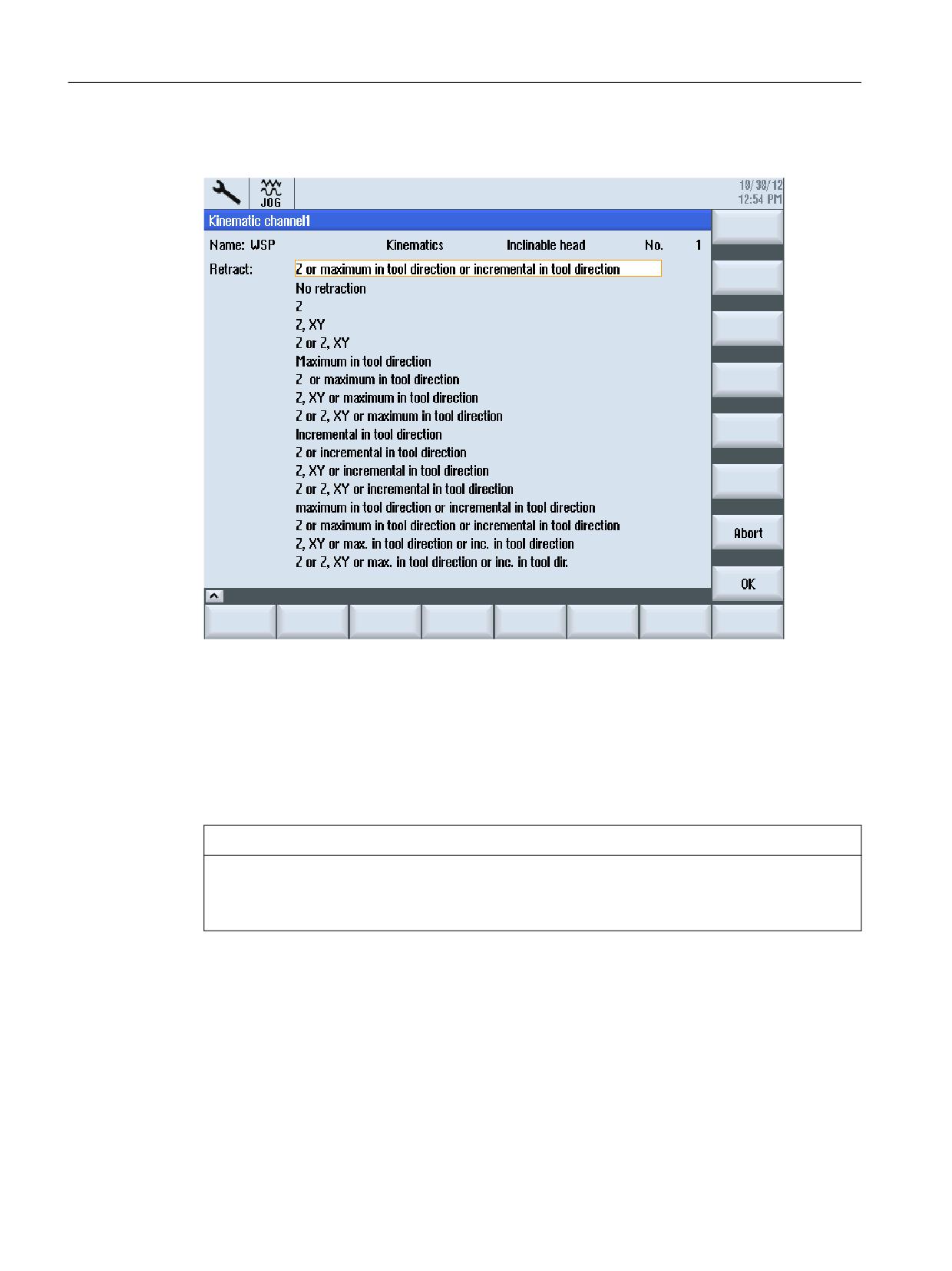
Retracting the geometry axes before swiveling
Figure 18-6
Dialog to select the type of retraction
Select the retraction variant in the input field: This is defined in the ONE MILLION and TEN
MILLION position of the system variable $TC_CARR37[n]:
● Retract axis Z
● Retract axes Z, XY
● Retract in the tool direction, maximum or incremental
NOTICE
Collision avoidance
Make sure that the tool and the workpiece cannot collide during swiveling when the tool axes
move.
Retraction of the axis Z or retraction of the axes Z, XY is implemented as an absolute machine
position to the values of parameters $TC_CARR38[n] to $TC_CARR40[n].
$TC_CARR38[n]
Retraction position X
$TC_CARR39[n]
Retraction position Y
$TC_CARR40[n]
Retraction position Z
SINUMERIK Operate
426
Commissioning Manual, 12/2019, 6FC5397-1DP40-6BA3
Technologies and cycles
18.7 Swiveling
The type of retraction is modified in the manufacturer cycle CUST_800.SPF (Page 438).
Note
Retraction in the tool direction is useful for swivel data sets in which the tool is re-oriented
(swivel head or mixed kinematics). This applies particularly for turning machines with a B axis.
During retraction in "maximum tool direction", traversing is performed until one of the relevant
linear axes reaches the software limit switch.
Backing up swivel data set
With the "Save data set" softkey in the dialog for the swivel data set, all of the entered
parameters ($TC_CARR1[n] to $TC_CARR65[n]) can be saved in a file in the part program
memory. The file name corresponds to the name of the swivel data set. Observe the permitted
characters when entering the swivel data set name.
Note
All of the vectors and parameters immediately take effect after being entered and do not have
to be additionally activated or saved.
SINUMERIK Operate
Commissioning Manual, 12/2019, 6FC5397-1DP40-6BA3
427
Technologies and cycles
18.7 Swiveling
18.7.4
Examples of machine kinematics for the commissioning of the Swivel function
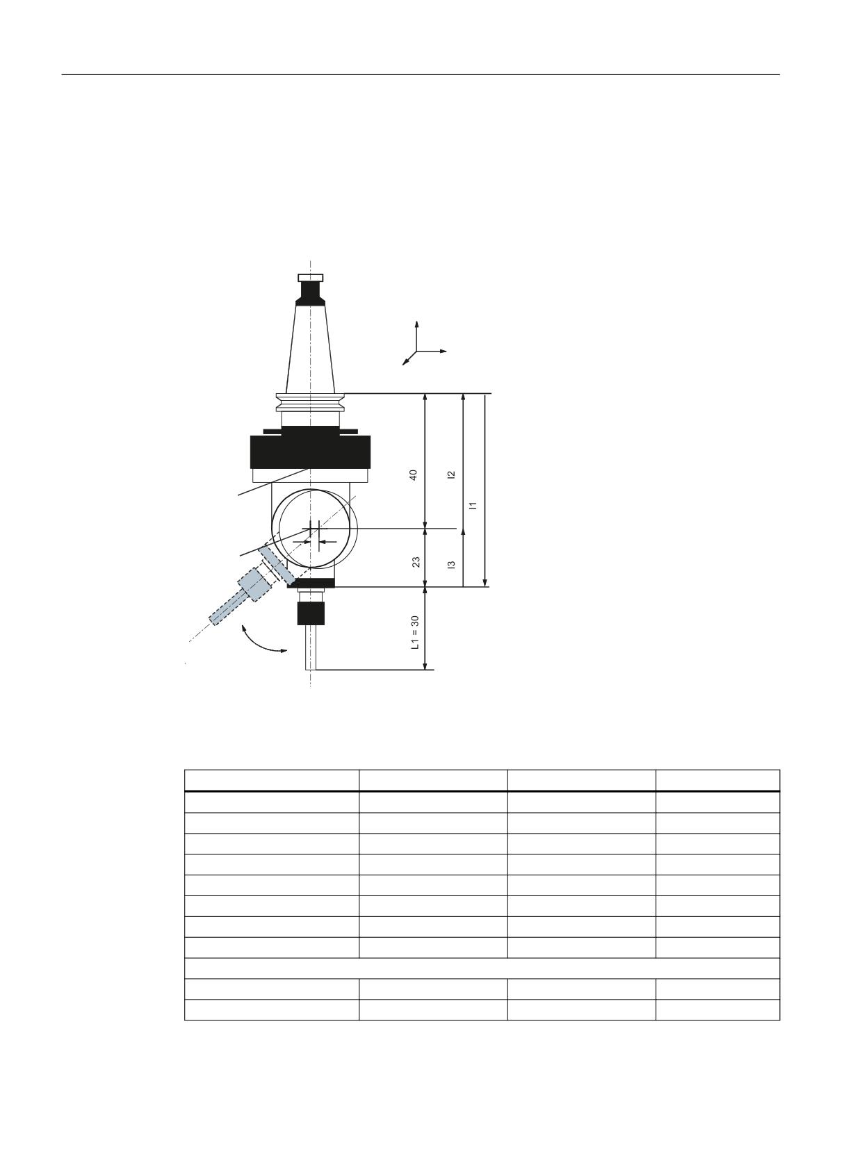
Example 1: Swivel head 1 "HEAD_1"
The vectors in the drawing refer to the initial setting of the kinematics. The drawing is not true
to scale. The swivel head is exchangeable and manually adjustable.
=
<
;
&
$
/ WRRO OHQJWK
C
Rotary axis 1 (manual) rotates about Z.
A
Rotary axis 2 (manual) rotates about X.
Figure 18-7
Exchangeable swivel head with steep taper to hold the spindle
Kinematics
Swivel head
HEAD_1
Retract
Z
X
Y
Z
200.000
Offset vector I1
0.000
0.030
-63.000
Rotary axis vector V1
0.000
0.000
1.000
Offset vector I2
0.000
0.000
40.000
Rotary axis vector V2
1.000
0.000
0.000
Offset vector I3
0.000
-0.030
23.000
Display version
Swivel mode
Axis-by-axis
Direction reference
Rotary axis 2
SINUMERIK Operate
428
Commissioning Manual, 12/2019, 6FC5397-1DP40-6BA3
Technologies and cycles
18.7 Swiveling
Kinematics
Swivel head
HEAD_1
Correct tool
No
Rotary axes
Rotary axis 1
C
Mode
Manual
Angular range
0.000
360.000
Rotary axis 2
A
Mode
Manual
Angular range
-15.000
100.000
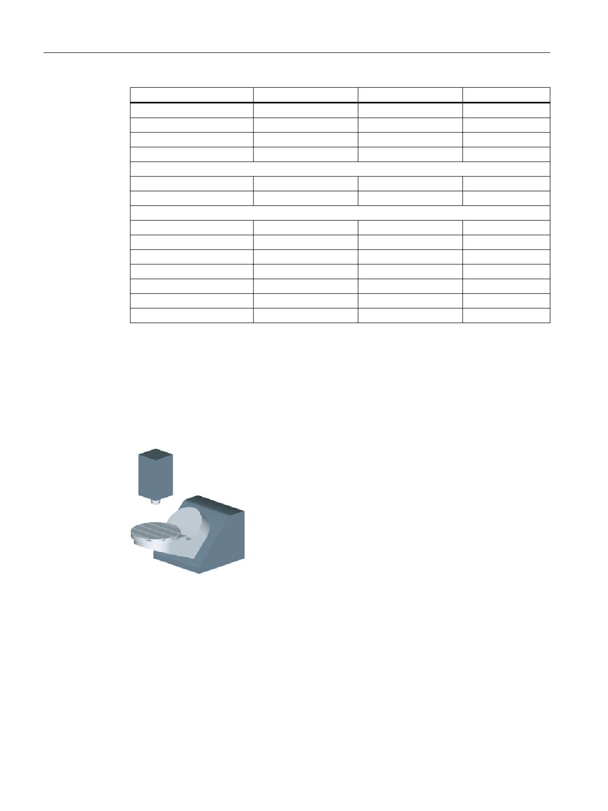
Example 2: Swivel head 2 "HEAD_2"
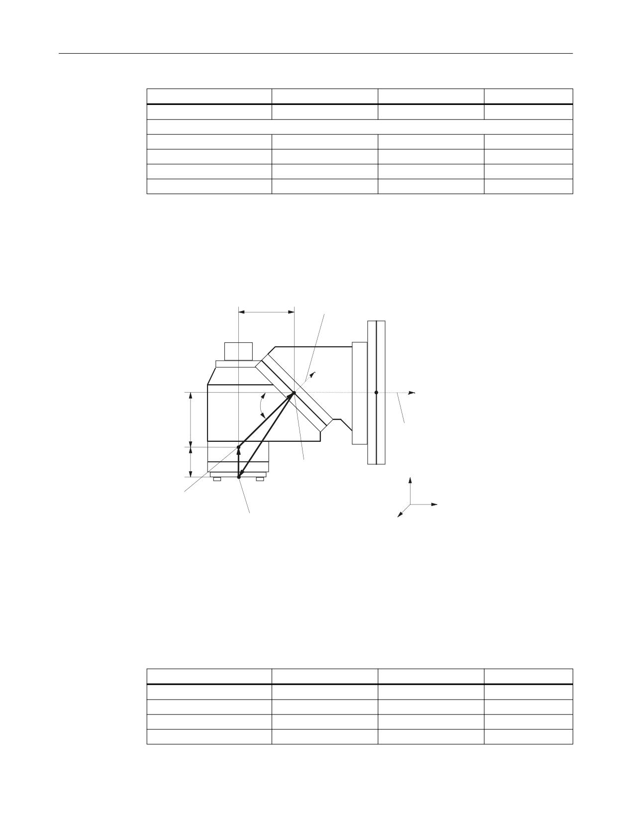
The vectors in the drawing refer to the initial setting of the kinematics. If the swivel head is fixed-
mounted, the vector chain is closed. The reference point of the center of rotation of rotary axes
1 and 2 can be offset on the line of rotation and does not have to coincide with the mechanical
center of rotation.
5RWDU\ D[LV
9
9
JUG
,
,
5RWDU\ D[LV
,
&HQWHU RI URWDWLRQ RI
=
URWDU\ D[LV
&HQWHU RI URWDWLRQ
RI URWDU\ D[LV
<
5HIHUHQFH SRLQW
;
RI WRRO
Rotary axis vector V1
Rotary axis 1 rotates about Y.
Rotary axis vector V2
Rotary axis 2 rotates about Y and about Z.
Offset vector I1
Closure of vector chain with fixed-mounted swivel head, I1 = - (I2 + I3).
Offset vector I2
The distance between the center of rotation of rotary axis 1 and center of
rotation of rotary axis 2
Offset vector I3
The distance between the reference point of the tool and the center of rotation
of rotary axis 2.
Figure 18-8
Cardanic swivel head with Hirth joint, manually adjustable
Kinematics
Swivel head
HEAD_2
Retract
Z
Tool direction
Max.+inc.
X
Y
Z
200.000
Offset vector I1
0.000
-172.000
-265.800
SINUMERIK Operate
Commissioning Manual, 12/2019, 6FC5397-1DP40-6BA3
429
Technologies and cycles
18.7 Swiveling
Kinematics
Swivel head
HEAD_2
Rotary axis vector V1
0.000
1.000
0.000
Offset vector I2
0.000
172.000
172.000
Rotary axis vector V2
0.000
1.0001)
1.0001)
Offset vector I3
0.000
0.000
93.800
Display version
Swivel mode
Axis-by-axis
Direction reference
Rotary axis 2
Rotary axes
Rotary axis 1
B
Mode
Manual
Angular range
0.000
360.000
Kinematics offset
0.000
Hirth joint
Yes
Angular grid
1.000
Rotary axis 2
C
Mode
Manual
Angular range
0.000
180.000
Kinematics offset
0.000
1) Calculation of rotary axis vector:
V2: 45 degree angle
V2Y = sin(-45) = -0.7071
V2Z = cos(-45) = 0.7071
V2Y and V2Z can be normalized to 1.
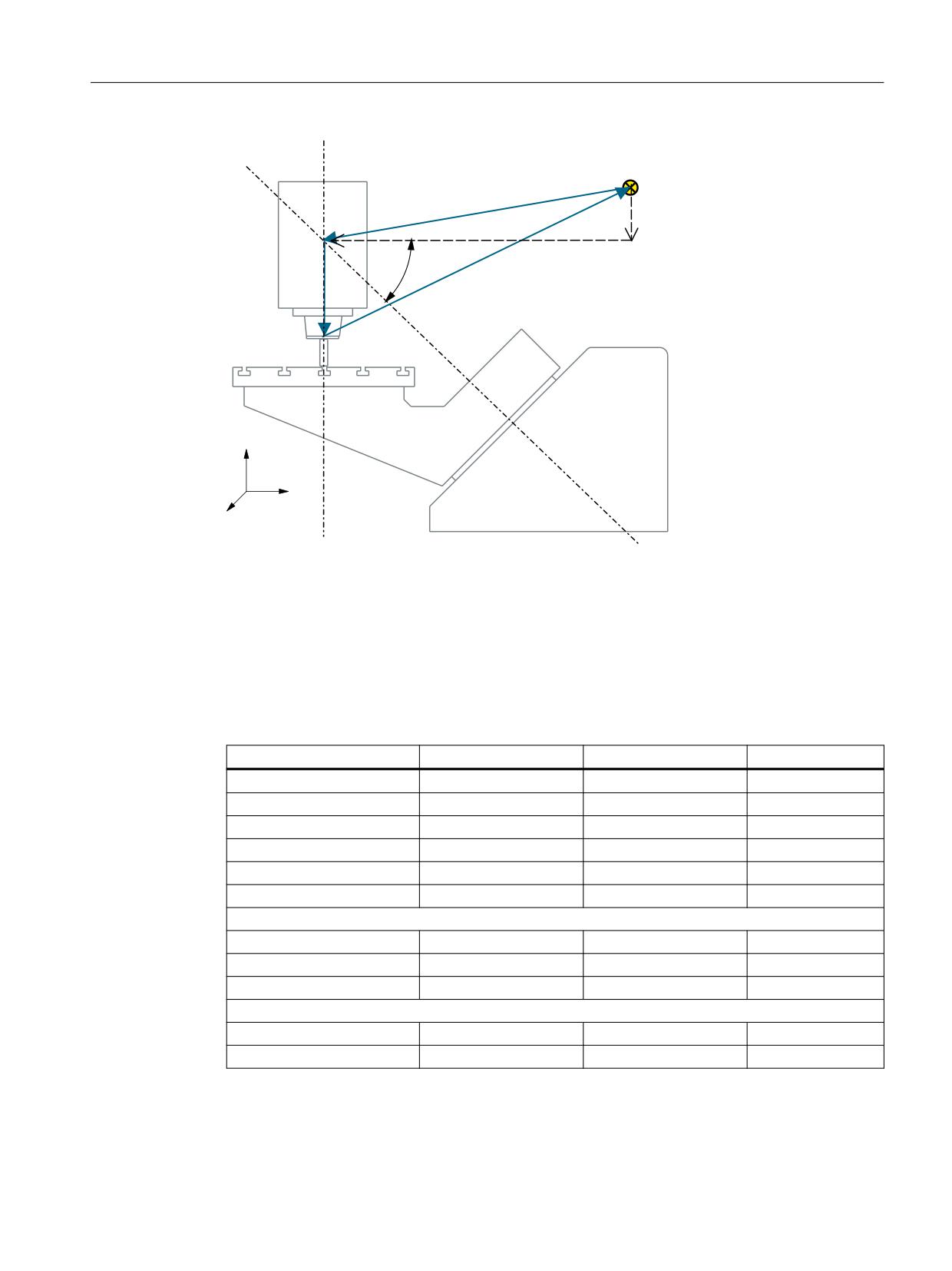
Example 3: Cardanic table "TABLE_45"
The vectors in the drawing refer to the initial setting of the kinematics. The spindle (tool adapter)
is positioned on a gage block above the top edge of the table/center of the table (rotary axis C).
A measuring rod in the spindle is used to determine the turning center of rotary axis C.
SINUMERIK Operate
430
Commissioning Manual, 12/2019, 6FC5397-1DP40-6BA3
Technologies and cycles
18.7 Swiveling
5HIHUHQFH SRLQW RI WKH PDFKLQH
0.6 ;
<
=
9
,
,
]
,
\
,
¡
,
]
,
5RWDU\ D[LV &
5RWDU\ D[LV %
=
9
<
;
Rotary axis vector V1
Rotary axis B rotates around Y and around Z.
Rotary axis vector V2
Rotary axis C rotates about Z.
Offset vector I2
The distance from the reference point of the machine to the center of rotation/
intersection of rotary axis 1.
Offset vector I3
The distance from the center of rotation/intersection of rotary axis 1 to the
center of rotation/intersection of rotary axis 2.
Offset vector I4
Closure of vector chain, I4 = - (I2 + I3).
Figure 18-9
Side view of the machine
Kinematics
Swivel table
TABLE_45
X
Y
Z
Offset vector I2
0.000
-100.000
-20.000
Rotary axis vector V1
0.000
-1.0001)
1.0001)
Offset vector I3
0.000
0.000
-30.000
Rotary axis vector V2
0.000
0.000
-1.000
Offset vector I4
0.000
100.000
50.000
Display version
Swivel mode
Axis-by-axis
Direction reference
Rotary axis 2
Correct tool
No
Rotary axes
Rotary axis 1
B
Mode
Auto
Angular range
0.000
180.000
SINUMERIK Operate
Commissioning Manual, 12/2019, 6FC5397-1DP40-6BA3
431
Technologies and cycles
18.7 Swiveling
Kinematics
Swivel table
TABLE_45
Rotary axis 2
C
Mode
Auto
Angular range
0.000
360.000
1) Calculation of rotary axis vector:
V1: β = -45 degrees
V1Y= sin(-45)= -0.7071
V1Z= cos(-45)= 0.7071
V1Y and V1Z can be normalized to -1 and 1.
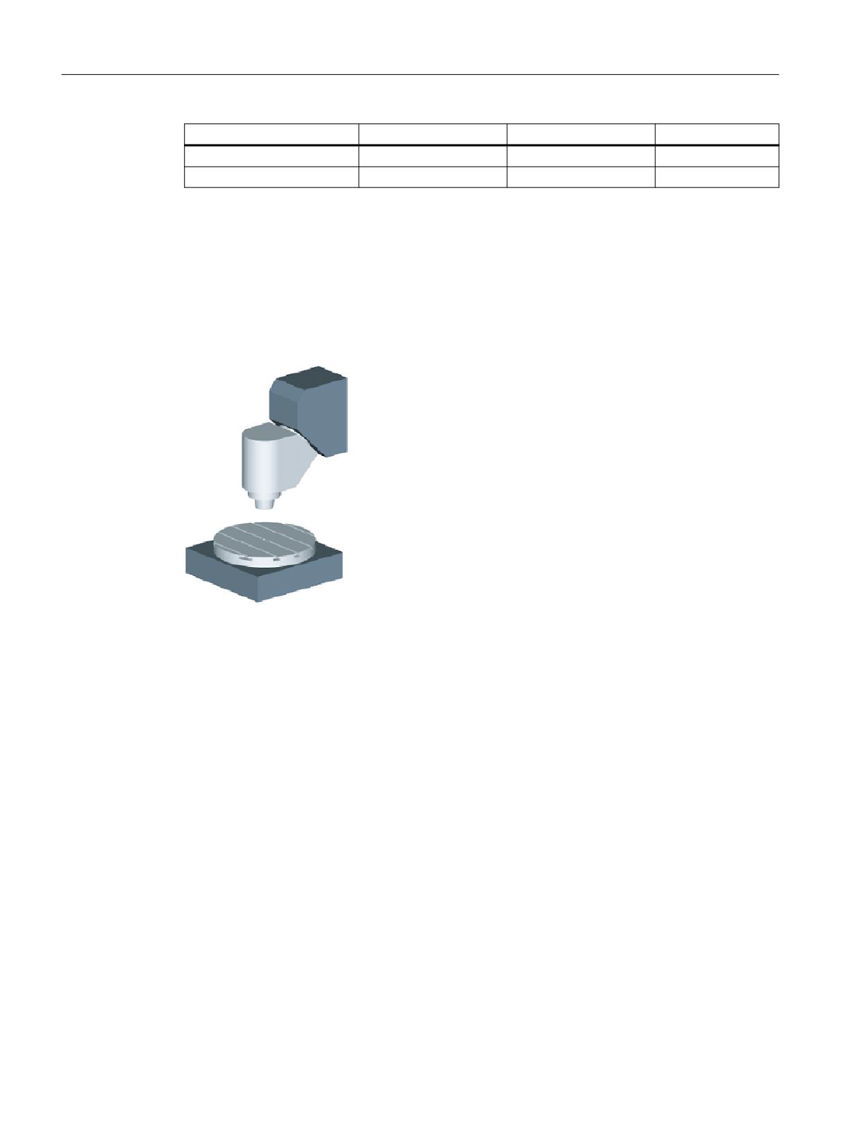
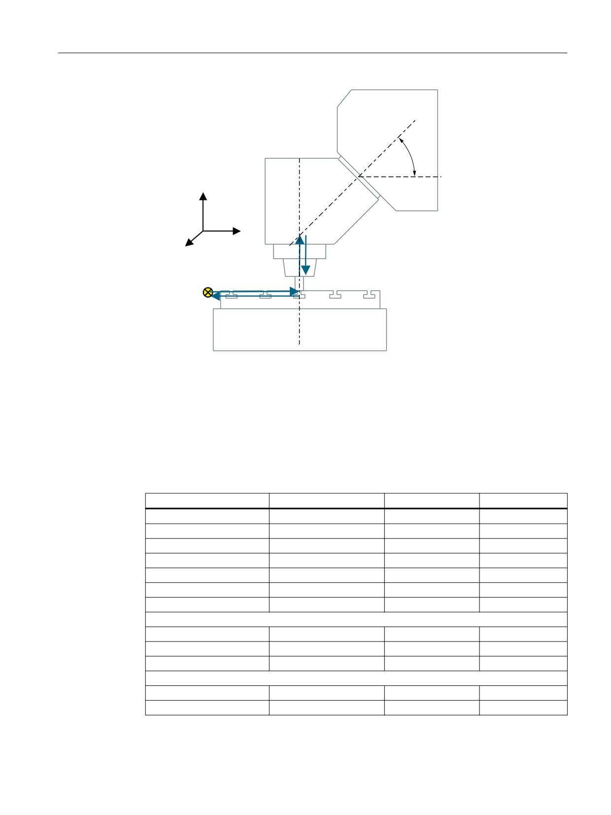
Example 4: Swivel head/rotary table "MIXED_45"
The vectors in the drawing refer to the initial setting of the kinematics. The spindle (tool adapter)
is positioned on a gage block above the top edge of the table/center of the table (rotary axis C).
A measuring rod in the spindle is used to determine the turning center of rotary axis C.
SINUMERIK Operate
432
Commissioning Manual, 12/2019, 6FC5397-1DP40-6BA3
Technologies and cycles
18.7 Swiveling
9
¡
=
5RWDU\ D[LV %
<
;
O
O
]
O
O
O
O
\
5HIHUHQFH SRLQW RI
O
O
5RWDU\ D[LV &
WKH PDFKLQH
0.6 ;
<
=
9
Rotary axis vector V1
Rotary axis B rotates around Y and around Z.
Rotary axis vector V2
Rotary axis C rotates about Z.
Offset vector I2
The distance from the reference point of the tool adapter to the center of
rotation/intersection of rotary axis 1
Offset vector I1
Closure of vector chain, I1 = - I2.
Offset vector I3
The distance from the reference point of the machine to the center of rotation/
intersection of rotary axis 2.
Offset vector I4
Closure of vector chain, I4 = - I3.
Figure 18-10
Side view of the machine
Kinematics
Mixed kinematics
MIXED_45
X
Y
Z
Offset vector I1
0.000
0.000
-30.600
Rotary axis vector V1
0.000
1.0001)
1.0001)
Offset vector I2
0.000
0.000
30.600
Offset vector I3
300.000
150.000
0.000
Rotary axis vector V2
0.000
0.000
-1.000
Offset vector I4
-300.000
-150.000
0.000
Display version
Swivel mode
Axis-by-axis
Direction
Rotary axis 1
Correct tool
Yes
Rotary axes
Rotary axis 1
B
Mode
Auto
Angular range
0.000
180.000
SINUMERIK Operate
Commissioning Manual, 12/2019, 6FC5397-1DP40-6BA3
433
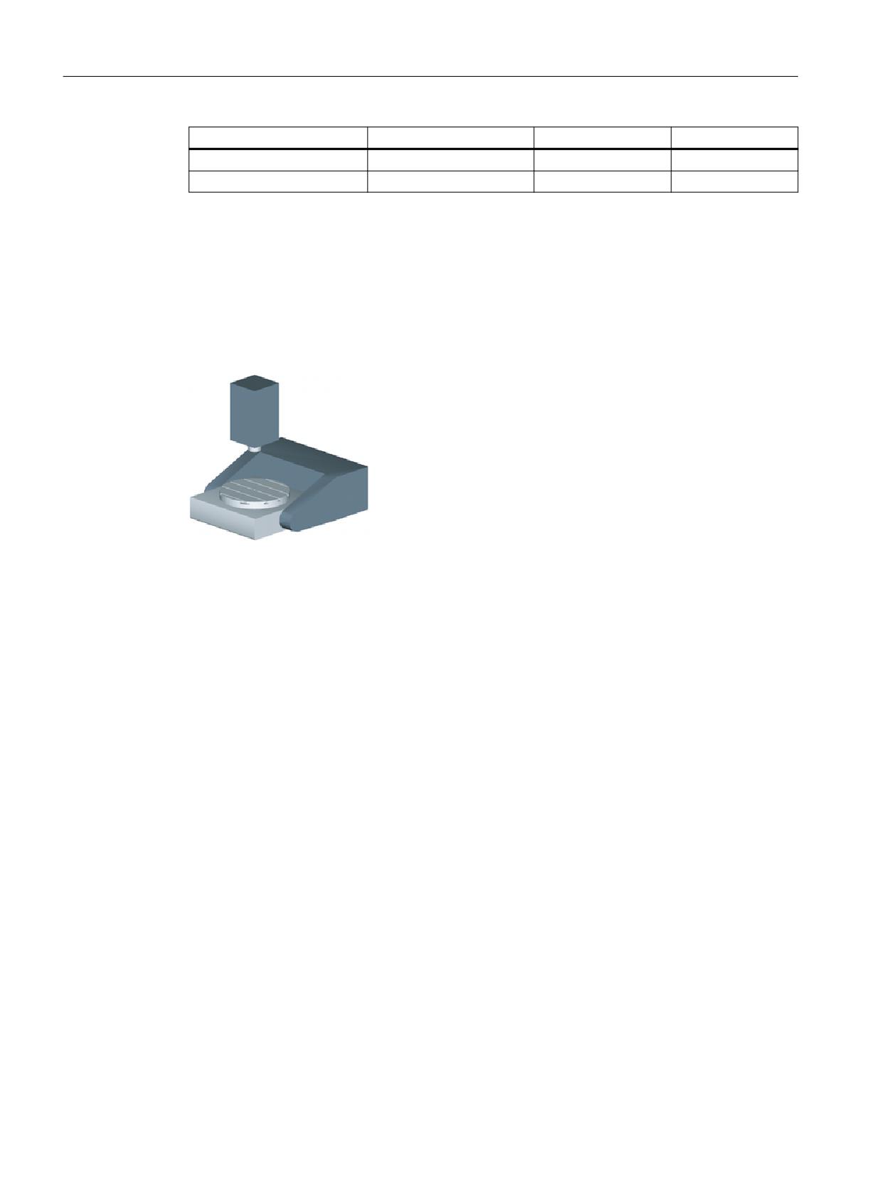
Technologies and cycles
18.7 Swiveling
Kinematics
Mixed kinematics
MIXED_45
Rotary axis 2
C
Mode
Auto
Angular range
0.000
360.000
1) Calculation of rotary axis vector:
V1: β = 45 degrees
V1Y= sin(-45)= -0.7071
V1Z= cos(-45)= 0.7071
V1Y and V1Z can be normalized to 1.
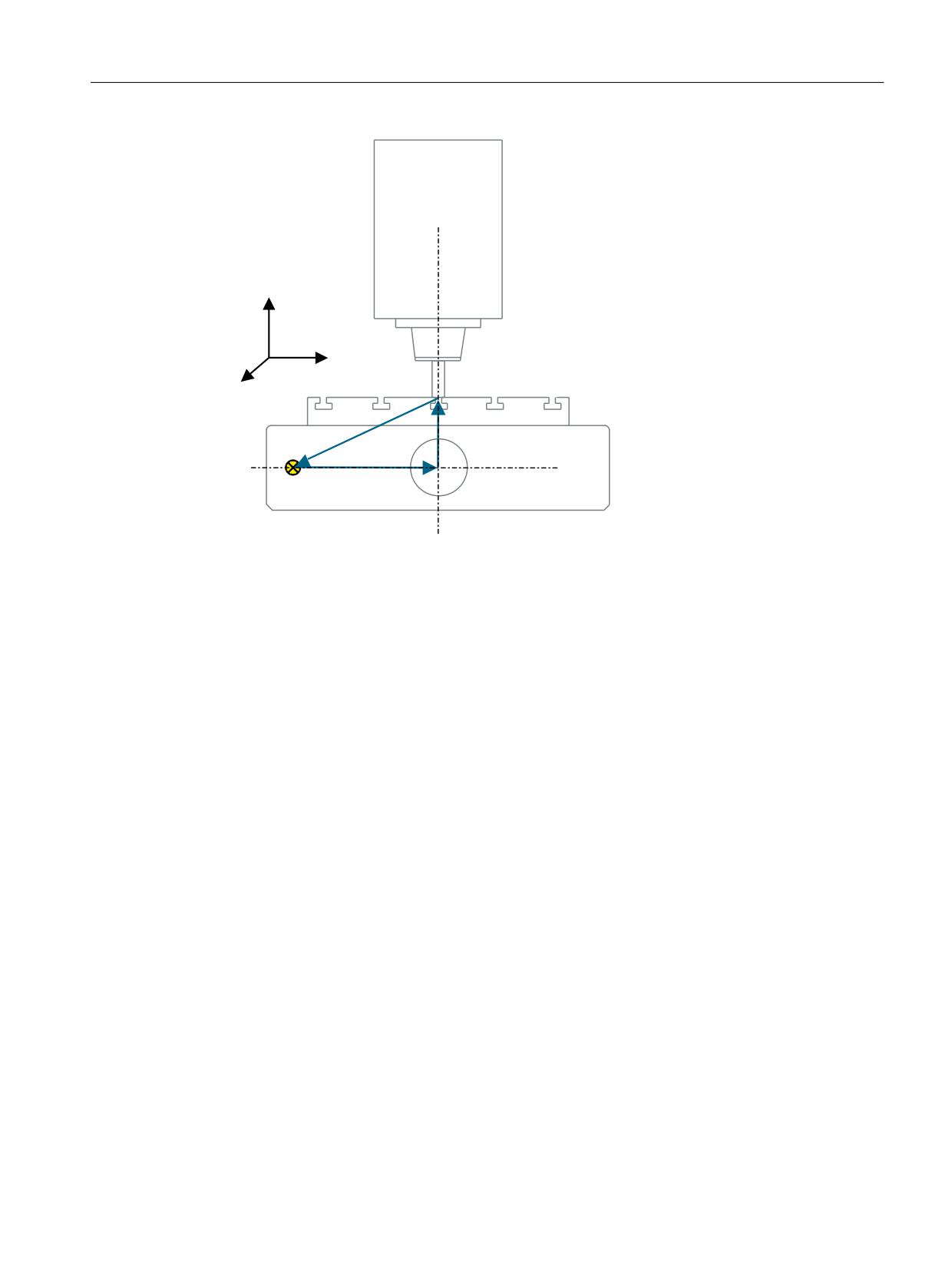
Example 5: Swivel table "TABLE_5"
The vectors in the drawing refer to the initial setting of the kinematics. The spindle (tool adapter)
is positioned on a gage block above the top edge of the table/center of the table (rotary axis C).
A measuring rod in the spindle is used to determine the turning center of rotary axis C.
SINUMERIK Operate
434
Commissioning Manual, 12/2019, 6FC5397-1DP40-6BA3
Technologies and cycles
18.7 Swiveling
9
=
<
;
5RWDU\ D[LV &
O
O
O
\
O
O
\
5RWDU\ D[LV $
5HIHUHQFH SRLQW RI
9
WKH PDFKLQH
0.6 ;
<
=
Rotary axis vector V2
Rotary axis C rotates about Z.
Offset vector I2
The distance from the reference point of the machine to the center of rotation/
intersection of rotary axis 1.
Offset vector I3
The distance from the center of rotation of rotary axis 1 to the center of rota-
tion/intersection of rotary axis 2.
Offset vector I4
Closure of vector chain, I4 = - (I2 + I3).
Figure 18-11
Side view of the machine from the X direction
SINUMERIK Operate
Commissioning Manual, 12/2019, 6FC5397-1DP40-6BA3
435
Technologies and cycles
18.7 Swiveling
9
=
<
;
5RWDU\ D[LV &
O
O
O
O
,
,
O
]
O
O
[
5RWDU\ D[LV $
9
5HIHUHQFH SRLQW RI
WKH PDFKLQH
0.6 ;
<
=
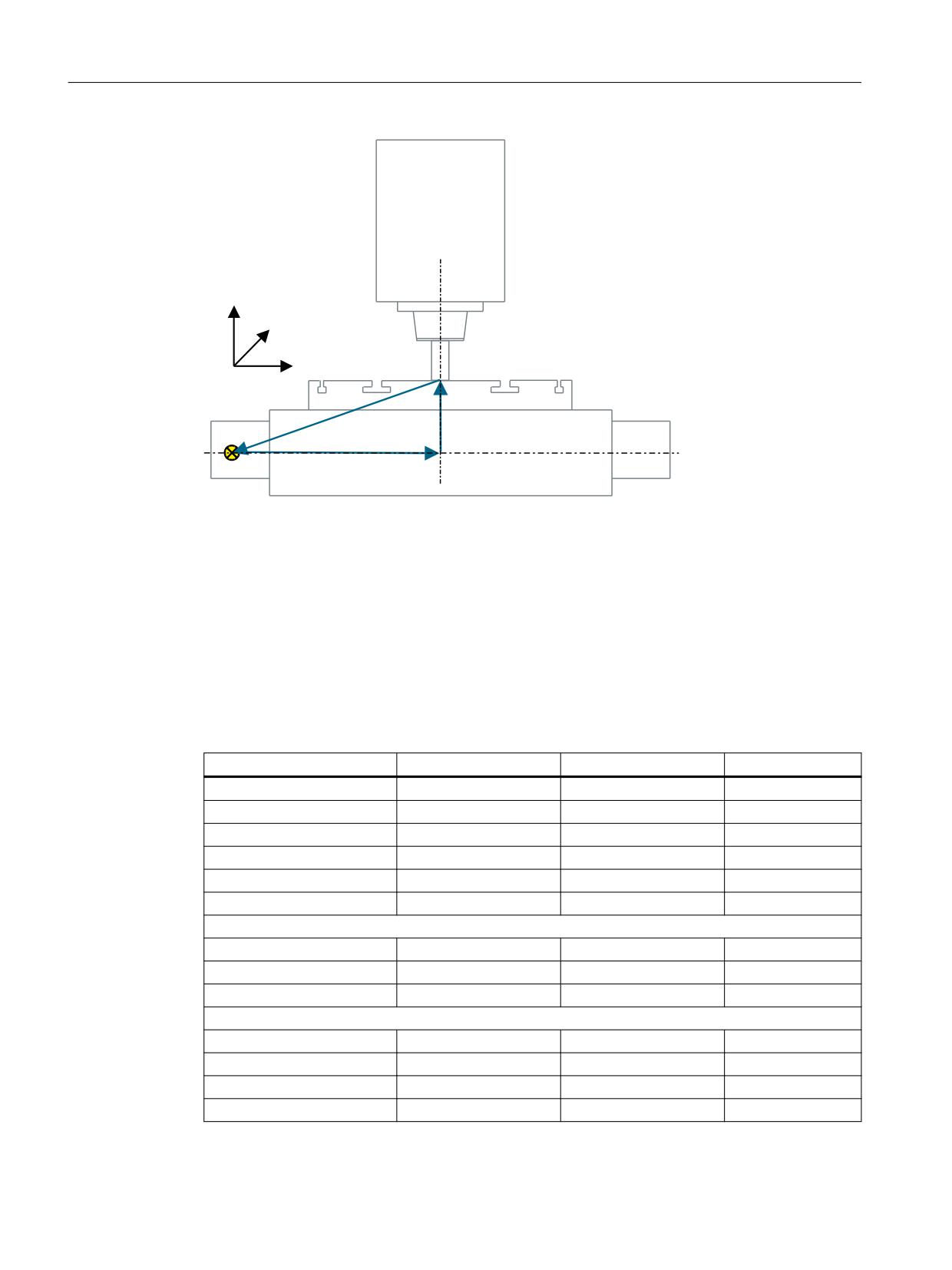
Rotary axis vector V1
The rotary axis A rotates about X.
Rotary axis vector V2
Rotary axis C rotates about Z.
Offset vector I2
The distance from the reference point of the machine to the center of rotation/
intersection of rotary axis 1.
Offset vector I3
The distance from the center of rotation of rotary axis 1 to the center of rota-
tion/intersection of rotary axis 2.
Offset vector I4
Closure of vector chain, I4 = - (I2 + I3).
Figure 18-12
Front view of the machine from the Y direction
Kinematics
Swivel table
TABLE_5
X
Y
Z
Offset vector I2
260.000
200.000
0.000
Rotary axis vector V1
-1.000
0.000
0.000
Offset vector I3
0.000
0.020
20.400
Rotary axis vector V2
0.000
0.000
-1.000
Offset vector I4
-260.000
-200.020
-20.400
Display version
Swivel mode
Axis-by-axis
Direction
Rotary axis 1
Correct tool
No
Rotary axes
Rotary axis 1
A
Mode
Auto
Angular range
-90.000
90.000
Rotary axis 2
C
Mode
Auto
Angular range
0.000
360.000
SINUMERIK Operate
436
Commissioning Manual, 12/2019, 6FC5397-1DP40-6BA3
Technologies and cycles
18.7 Swiveling
Example 6: Setting up a turning machine with B axis
For turning machines with an additional rotary axis B, the tool can be aligned or swiveled on the
X/Z plane. If your machine has a counterspindle, you can, for example, machine with a tool
alternating between the main spindle and counterspindle.
You require the following swivel data sets to use the "Align tool" and "Swivel plane" functions:
● Swivel data set 1 for aligning and swiveling tools on the main spindle and counterspindle
(turning, face Y/C, surface Y/C).
● Swivel data set 2 for machining inclined surfaces when milling on the main spindle (face B).
● Swivel data set 3 for machining inclined surfaces when milling on the counterspindle (face
B).
When commissioning the "B-axis kinematics turning technology" in parameter
$TC_CARR37[n], the TEN THOUSANDS position must be set to 2 or 3 in swivel data set 1. This
is the reason why in the program editor "Swivel tool → align turning or milling tool" is listed for
swivel data set 1.
See also Section "Commissioning swivel data (machine kinematics) (Page 417)"
Example 7: Configuring a milling machine with B axis for turning.
You can configure a milling machine with a B axis (rotation around Y) so that turning is possible.
The following example refers to a milling machine with a rotary axis around Y (B), a rotary axis
around Z (C) and a main spindle (SP) in the tool direction Z (G17).
You require the following swivel data sets to use the "Align tool" and "Swivel plane" functions:
● Swivel data set 1 for "Swiveling in the plane" when milling.
Mixed kinematics: Rotary axis 1: B-axis, rotary axis 2: C axis
● Swivel data set 2 for the "Swivel tool - align tool" when turning
Swivel head: Rotary axis 1: B-axis, rotary axis 2: Spindle SP
When milling, the SP spindle is the master spindle. Rotary axis C is declared as the master
spindle in rotational operation, e.g. SETMS(2).
When commissioning the "B-axis kinematics turning technology" in parameter
$TC_CARR37[n], the TEN THOUSANDS position must be set to 2 or 3 in swivel data set 2. This
is the reason why in the program editor "Swivel tool → align turning or milling tool" is listed for
swivel data set 2.
See also Section "Commissioning swivel data (machine kinematics) (Page 417)"
SINUMERIK Operate
Commissioning Manual, 12/2019, 6FC5397-1DP40-6BA3
437

Technologies and cycles
18.7 Swiveling
Parameter CUTMOD in CYCLE800
Distinction between calls:
● The CUTMOD NC function is activated when data set 2 is called in the NC program
(CYCLE800 align turning tool). This means that the cutting edge position or the tool
reference point is updated corresponding to the tool orientation:
● When calling a swivel data set for rotational operation in the NC program (CYCLE800 align
tool), the CUTMOD NC function is activated. The cutting edge position, tool angle, cut
direction and tool reference point are thus calculated in accordance with the current tool
orientation following the "Align tool" function.
Additional information
A more detailed description of parameter CUTMOD is provided in the
Function Manual Tools
18.7.5
Manufacturer cycle CUST_800.SPF
Function
During swiveling, all axis positions are approached using the CUST_800.SPF cycle. The call is
exclusively made from the swivel cycle CYCLE800 or from the cycles
E_TCARR (ShopMill) or F_TCARR (ShopTurn).
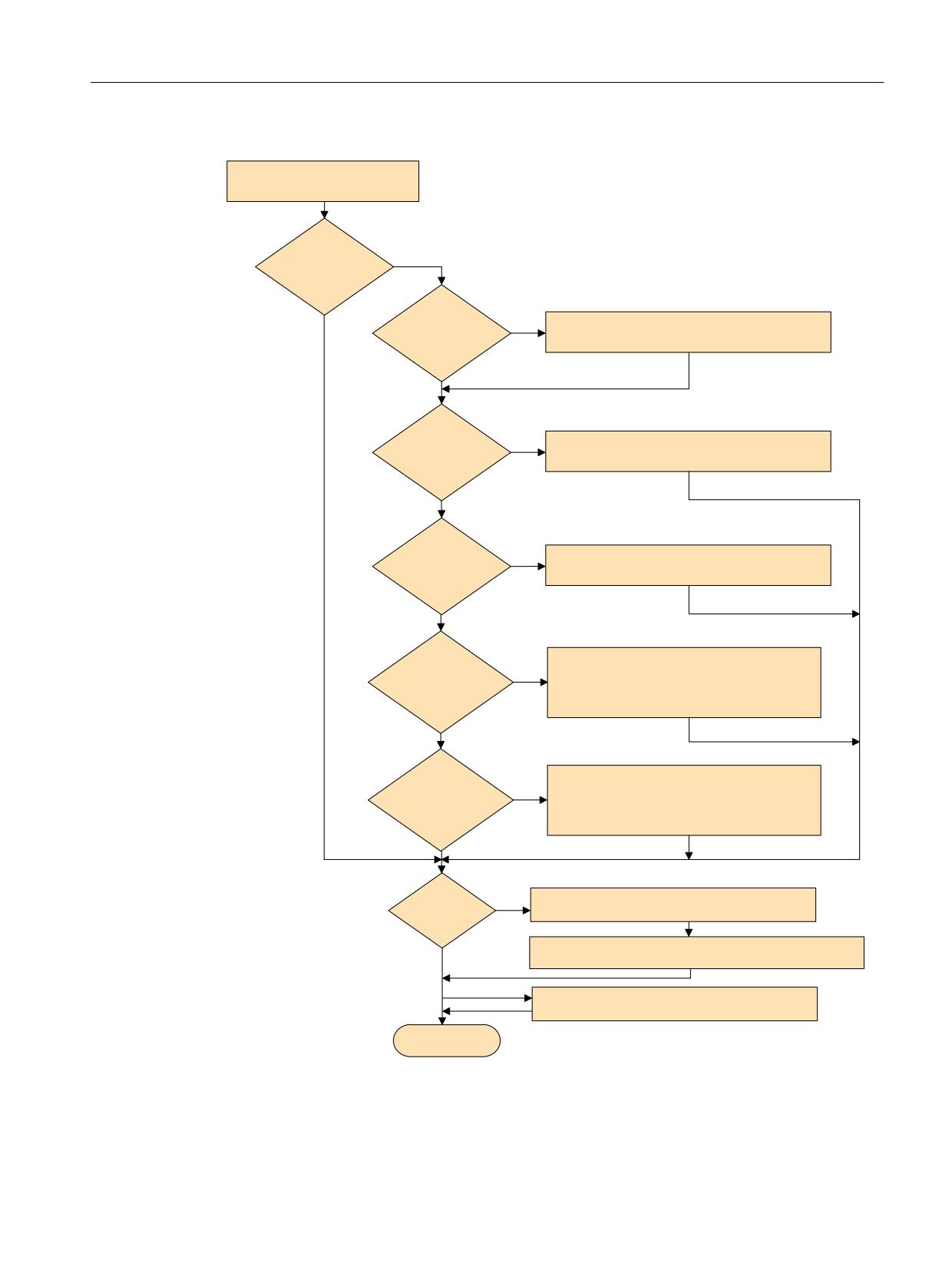
In cycle CUST_800.SPF, the function markers (_M2: to _M59) are prepared and documented.
Also refer to the following "Structogram CYCLE800".
There are extensions in the CUST_800.SPF cycle for the "Turning on milling machine" function,
see Chapter "Adaptations for CUST_800 (Page 457)".
Note
If you modify the CUST_800, ensure that the G commands of the G groups used are restored
at the end of the CUST_800 (versions S_G_1 to S_G_5!).
Parameter
CUST_800 (INT _MODE, INT _TC1, REAL _A1, REAL _A2, INT _TC2, REAL _T_POS)
_MODE
A jump is made to markers _M2 to _M59
_TC1
Number of the swivel head/table
_A1
Angle of rotary axis 1
_A2
Angle of rotary axis 2
_TC2
Feed evaluation in percent (%) for swiveling in JOG mode and number of the new swivel
head/table when replaced in ShopMill
_T_POS
Incremental position during retraction in the incremental tool direction (see marker _M44,
_M45)
SINUMERIK Operate
438
Commissioning Manual, 12/2019, 6FC5397-1DP40-6BA3
Technologies and cycles
18.7 Swiveling
Retract prior to swiveling
If the CUST_800.SPF cycle is not modified, the Z axis (marker _M41) or the Z axis followed by
the X, Y axes (marker _M42) are first traversed in the Machine to the positions when retracting
prior to swiveling. The freely available position values are specified in the system variables
$TC_CARR38[n] to $TC_CARR40[n]. When retracting, the active tool cutting edge is
deselected (D0) and is reselected after retraction.
If retraction in the tool direction has been declared, the tool axis is retracted to the software end
position (maximum in tool direction) or by an incremental distance away from the tool in the tool
direction. The tool lengths are taken into account accordingly.
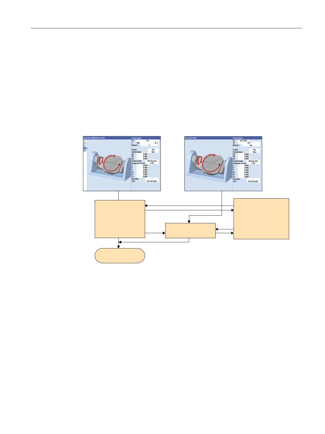
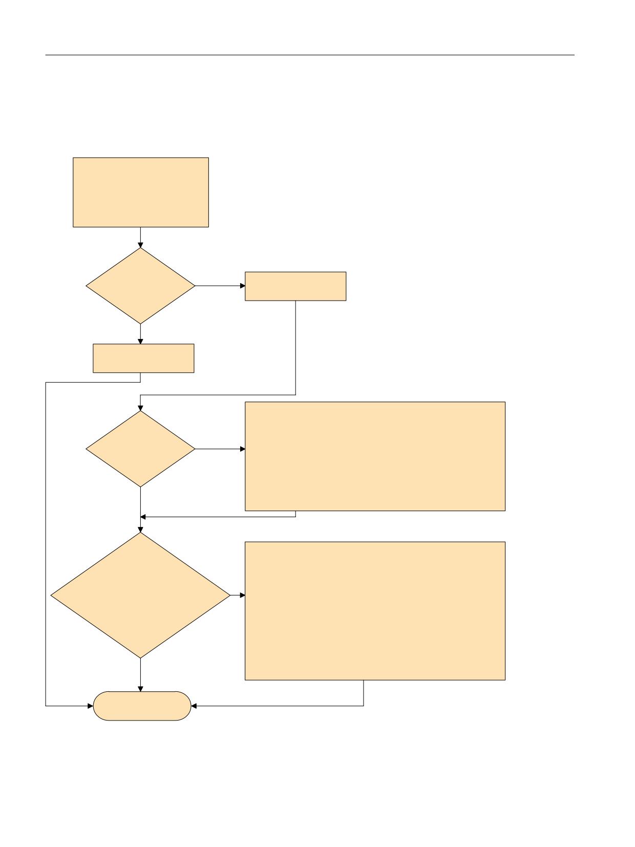
6WUXFWXUH FRDUVH RI VZLYHO F\FOHV
,QSXW VFUHHQ IRUP XQGHU 6KRS0LOO 6KRS7XUQ
,QSXW VFUHHQ IRUP IRU &<&/(
VWDQGDUG F\FOH
&867B
63)
/DEHO B0
B0
(B7&$55 63)
)B7&$55 63)
&<&/(
63)
/DEHO B0
B0
(QG RI F\FOH
Figure 18-13
Structure (coarse) of swivel cycles
SINUMERIK Operate
Commissioning Manual, 12/2019, 6FC5397-1DP40-6BA3
439
Technologies and cycles
18.7 Swiveling
CYCLE800 structured chart
Sequence in AUTOMATIC mode
6WUXFWXUH &<&/(
63)
&867B
63)
,QSXW SDUDPHWHUV
QDPH RI VZLYHO GDWD VHW
PRGH
RIIVHWV
URWDWLRQV
UHWUDFWLRQ
&DOFXODWLRQ RI
,QLW
YDOLG VZLYHO GDWD VHW
/DEHO B0 ,QLW
5HZULWH YHFWRUV
NLQHPDWLF FKDLQ LV SRVVLEOH
IRU H[DPSOH WHPSHUDWXUH FRPSHQVDWLRQ
YHFWRUV RU LQFOXVLRQ RI
: D[LV LQ GULOOLQJ WRROV
6ZLYHO GDWD VHW LQYDOLG
)DXOW PHVVDJHV
$GDSWLQJ WKH UHWUDFWLRQ VWUDWHJ\
/DEHO
B0
= D[LV
B0
= D[LV ;< D[LV
5HWUDFWLRQ
B0
WRRO GLUHFWLRQ PD[
7RRO D[LV
B0
WRRO GLUHFWLRQ LQF
B0
UHWUDFWLRQ RI = D[LV
WR 0&6 IL[HG SRVLWLRQ EHIRUH WRRO DOLJQPHQW
B0
UHWUDFWLRQ RI =
;< D[LV
WR 0&6 IL[HG SRVLWLRQ EHIRUH WRRO DOLJQPHQW
1R UHWUDFWLRQ
7UDYHUVH URWDU\ D[HV IRU 1& D[HV
/DEHO
B0
VZLYHO URWDU\ D[HV
DXWRPDWLFDOO\
FDOFXODWLRQ RI WKH
B0
VZLYHO URWDU\ D[LV DXWRPDWLFDOO\
URWDU\ D[LV DQJOH
URWDU\ D[LV PDQXDOO\ RU VHPLDXWRPDWLFDOO\
GLVSOD\ DQJOH YDOXHV WR EH VHW
PDQXDO URWDU\ D[HV
B0
VZLYHO URWDU\ D[LV DXWRPDWLFDOO\
GHDFWLYDWH D[LV WUDQV
B0
VZLYHO URWDU\ D[LV PDQXDOO\ RU VHPLDXWRPDWLFDOO\
IRUPDWLRQ
B0
VZLYHO URWDU\ D[LV DXWRPDWLFDOO\
URWDU\ D[LV PDQXDOO\ RU VHPLDXWRPDWLFDOO\
B0
VZLYHO URWDU\ D[HV
PDQXDOO\ RU
VHPLDXWRPDWLFDOO\
1R WUDYHUVLQJ
B0
B0
B0
VZLYHO LQ -2* ZLWK 75$25,
RI URWDU\ D[HV
(QG RI F\FOH
Figure 18-14
Structure: CYCLE800.SPF / CUST_800.SPF
SINUMERIK Operate
440
Commissioning Manual, 12/2019, 6FC5397-1DP40-6BA3
Technologies and cycles
18.7 Swiveling
6WUXFWXUH (B7&$55 63) )B7&$55 63)
&867B
63)
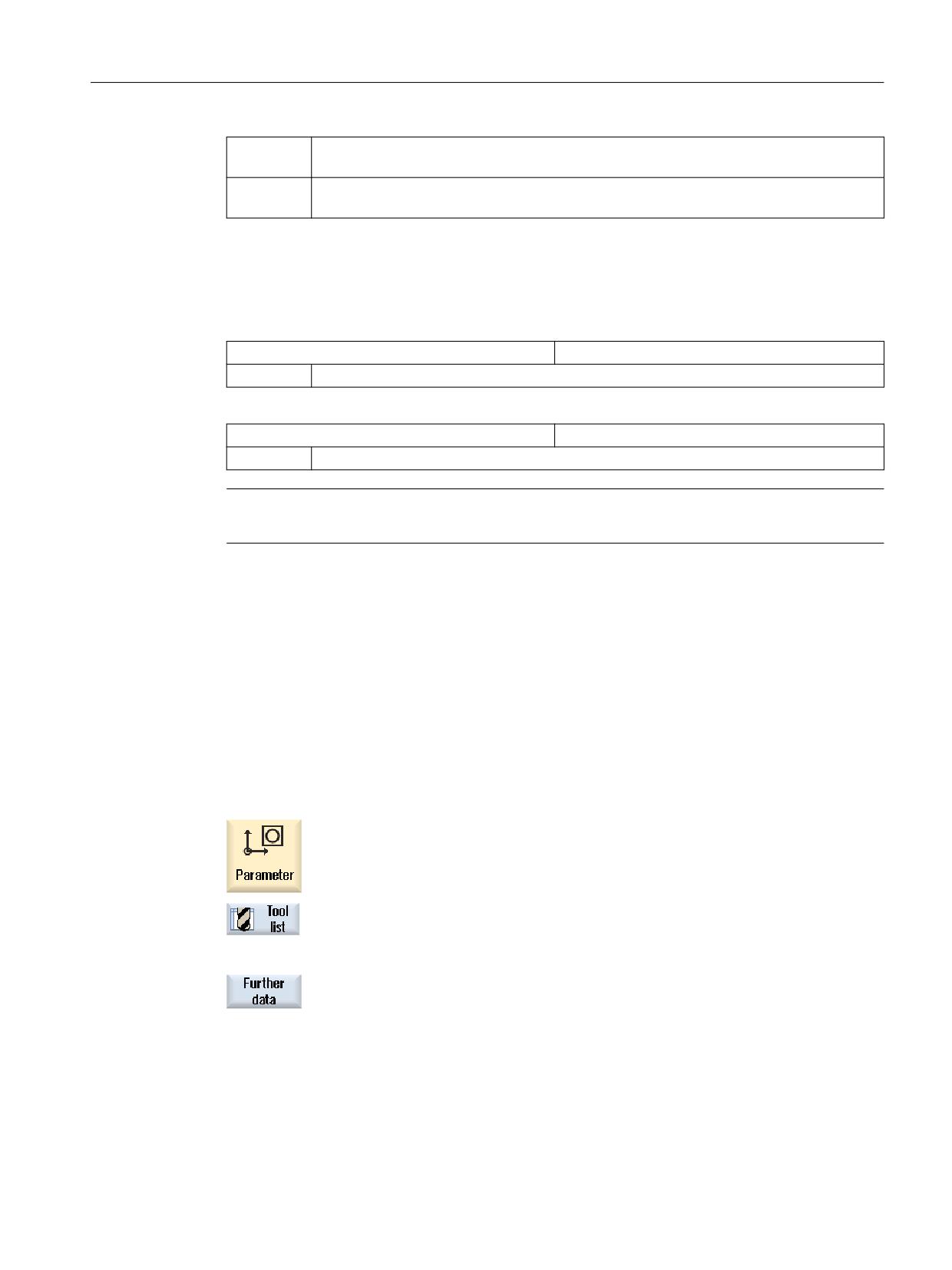
7KH IROORZLQJ VWUXFWXUH UHIHUV WR WKH VZLYHO GDWD EORFN FKDQJH DQG WKH
7RRO QDPH
DVVRFLDWHG WRRO FKDQJH XQGHU PLOOLQJ WXUQLQJ
,QSXW GDWD IRU VZLYHOLQJ
6'6
! 6ZLYHO GDWD VHW
\HV
2OG 6'6
1HZ 6'6"
QR
2OG 6'6
\HV
/DEHO B0
&KDQJH PDJD]LQH WRRO
6ZLYHO
B0
&KDQJH PDQXDO WRRO
KHDG"
QR
$XWRPDWLFDOO\
\HV
/DEHO B0
$XWRPDWLFDOO\ FKDQJH
FKDQJH
VZLYHO KHDG WDEOH
6'6 ROG QHZ"
QR
$XWRPDWLFDOO\
\HV
/DEHO B0
0DQXDOO\ FKDQJH
FKDQJH
VZLYHO KHDG WDEOH
6'6 ROG QHZ"
QR
$XWRPDWLFDOO\
/DEHO B0
$XWRPDWLFDOO\ FKDQJH
FKDQJH
\HV
VZLYHO KHDG WDEOH"
6'6 ROG
/DEHO B0
$XWRPDWLFDOO\ FKDQJH
0DQXDOO\ FKDQJH
VZLYHO KHDG WDEOH"
6'6 QHZ"
QR
/DEHO B0
0DQXDOO\ FKDQJH
0DQXDOO\ FKDQJH
\HV
VZLYHO KHDG WDEOH"
6'6 ROG"
/DEHO B0
$XWRPDWLFDOO\ FKDQJH
$XWRPDWLFDOO\ FKDQJH
6'6
VZLYHO KHDG WDEOH"
QHZ"
QR
\HV
/DEHO B0 &KDQJH PDJD]LQH WRRO
7RRO
B0
&KDQJH PDQXDO WRRO
FKDQJH"
/DEHO B0
6ZLYHO DIWHU WRRO FKDQJH
$872
QR
B0
6ZLYHO DIWHU WRRO FKDQJH -2*
/DEHO B0
5HWUDFWLRQ DIWHU VZLYHOLQJ
(QG RI F\FOH
Figure 18-15
Structure: E_TCARR.SPF (F_TCARR.SPF) / CUST_800.SPF
SINUMERIK Operate
Commissioning Manual, 12/2019, 6FC5397-1DP40-6BA3
441
Technologies and cycles
18.7 Swiveling
Note on markers _M2 to _M13
When the swivel data set or tool is changed, the linear axes are recovered using the last
retraction mode (modal).
If this behavior is not desired in milling/turning, the corresponding calls must be commented out
with a semicolon (;). The E_SWIV_H or F_SWIV_H cycle is called in milling/turning (see
markers _M2 to _M9) in the CUST_800.SPF manufacturer cycle.
Parameter E_SWIV_H (Par1, Par2, Par3)
● Par1: Number of swivel data set (_TC1)
● Par2: Angle 1st rotary axis
● Par3: Angle 2nd rotary axis
Modification examples
If the rotary axes (swivel head/table) are not to be positioned during swivel data change / tool
change, the call of the E_SWIV_H cycle can be commented out at the relevant markers. If the
rotary axes are to move to a certain position, an angle value can be transferred to parameters
Par 2, Par 3.
Note on labels _M14, _M15
Depending on the values of the retraction plane and the programmed swivel plane, it is possible
that the linear axes now also travel the swiveled retraction plane while running up from the
current position to the software limit switches after a block search. To avoid this problem, label
_M14 in the CUST_800.SPF is called after swiveling. The E_SP_RP(30) cycle preset there runs
up to the milling retraction plane, whereby travel may be along the software limit switches. An
appropriate retraction after block search can be set at label _M15.
Note on the label _M16
If for a swivel data set change or when de-selecting the swivel data set, you wish to traverse the
rotary axes to zero, the syntax of the _M16 label can be modified accordingly, e.g. activate block
N8006 E_SWIV_H(_TC1,0,0).
Note on labels _M20 to _M31
Markers _M20 to _M31 are distinguished by machine kinematics with two rotary axes or one
rotary axis. A distinction is also made between automatic rotary axes (known to the NCU) and
manual (semi-automatic) rotary axes. There is only ever one valid label for swiveling with the
active swivel data set.
Note on label _M35
Run through _M35 for block search and a swivel data set with manual rotary axes.
SINUMERIK Operate
442
Commissioning Manual, 12/2019, 6FC5397-1DP40-6BA3
Technologies and cycles
18.7 Swiveling
Note on label _M40
This label is called before the calculation and activation of the tool holder function as user
initialization. This makes it possible for special kinematics, to calculate or rewrite the current
vectors of the active swivel data set.
Boring mill application example: For parallel axes, the vector in the Z direction can be updated
with the actual value of the W axis.
A STOPRE is integrated for this label.
Manufacturers can test as to whether this STOPRE for label M40 in CUST_800.spf complies
with their functional requirements. In this case, one must weigh up between velocity (without
STOPRE) and functionality for interrupt conditions (RESET) for a swivel plane. This also
depends on the type of machine kinematics.
Note on labels _M41 to _M45 and _M47, _M48
At marks _M41 to _M45, the retraction strategy can be modified before the swiveling of the
rotary axes and at marks _M47 and _M48 before the alignment of the tool.
The retraction to the MCS positions Z or Z, XY is made considering the tool length components
without tool cutter deselection.
Note on labels _M41 and _M42
When retracting in Z or Z, XY with mixed swivel head kinematics, the NC takes account of the
kinematics reference point. If the head is tilted, positions are approached that might deviate
from the values of the retraction position $TC_CARR38 to $TC_CARR40.
If you do not want this, you can deactivate and then reactivate the current tool holder at the
labels _M41/_M42 and in the calculations of the tool components in cycle CUST_800.SPF.
Example:
IF (_MODE==41)OR(_MODE==42)
TCARR=0 ;deactivate tool holder
IF $P_GG[6]==1
ENDIF
TCARR=_TC1 ;reactivate tool holder
ENDIF
_M41: ;axis Z MCS fixed point
TCARR=0 ;deactivate tool holder
IF($MN_G53_TOOLCORR
ENDIF
TCARR=_TC1 ;reactivate tool holder
Note on label _M46
Retraction before swiveling after a block search can be set at label _M46. Variable _E_VER is
1 if it is a milling technology program.
SINUMERIK Operate
Commissioning Manual, 12/2019, 6FC5397-1DP40-6BA3
443
Technologies and cycles
18.7 Swiveling
Note on labels _M57 to _M59
Labels _M57 to _M59 are used for swiveling in JOG mode and active 5-axis transformation
(TRAORI).
Note on "Correct tool"
"Correct tool" requires that a 5-axis transformation is set up which is equivalent to the
corresponding swivel data set. The programming section for "Correct tool" is integrated in the
markers _M20, _M21, _M22 and _M30. The first 5-axis transformation is called with TRAORI(1).
Note on tool change + swivel
In general, the swivel (CYCLE800) and tool change functions for a machine are independent
of each other. Thus, the swiveled work plane can be retained in a technological sequence with
multiple tools, e.g. centering, drilling, tapping.
If the rotary axes of the active swivel data set are involved in the mechanical sequence of the
tool change or have to be retracted, this must be taken into account in the tool change program.
After the tool change, the rotary axis positions are approached as prior to the tool change. If
linear axes (geometry axes) are also involved in the tool change, the rotations in the NC (swivel
frame) must not be deleted. Rather, the linear axes can be positioned as machine axes using
the G153 or SUPA commands.
Note on swiveling without active tool compensation
If swiveling the rotary axes without active tool cutting edge (D0) is not possible, then you can
adapt this in cycle CUST_800.SPF:
_M40:
IF ((NOT $P_TOOL) AND _TC1)
LOOP
MSG ("No tool cutting edge active")
M0
STOPRE
ENDLOOP
ENDIF
GOTOF_MEND
18.7.6
Indirectly programming the name of the swivel data set
Function
The _TC_CHANGE GUD variable defined in the channel is a string with a length of 32. Using
this variable, the user can determine before the CYCLE800 call which swivel data set is called
in the CYCLE800, irrespective of what is programmed in the call itself.
The _TC_CHANGE GUD variable is re-initialized with each RESET. At the end of the
CYCLE800, the variable is also deleted. This means that the variable must be re-described
before each new CYCLE800 call.
SINUMERIK Operate
444
Commissioning Manual, 12/2019, 6FC5397-1DP40-6BA3
Technologies and cycles
18.7 Swiveling
The swivel data set is changed in the CYCLE800 following the CUST_800 jump to the _M40
marker. This means that the variable can also be described in the CUST_800.
Programming example
N10 _TC_CHANGE="HEAD_2"
N20 CYCLE800(0,"HEAD_1",100000,57,0,0,0,0,0,0,0,0,0,-1,100,1)
N30 M0 ;* HEAD_2 is active
N40 _TC_CHANGE="HEAD_3"
N50 CYCLE800(0,"HEAD_1",100000,57,0,0,0,0,0,0,0,0,0,-1,100,1)
N60 M0 ;* HEAD_3 is active
N70 CYCLE800(0,"HEAD_1",100000,57,0,0,0,0,0,0,0,0,0,-1,100,1)
N80 M0 ;* HEAD_1 is active
N90 _TC_CHANGE="TABLE_2"
N100 CYCLE800(0,"TABLE_1",100000,57,0,0,0,0,0,0,0,0,0,-1,100,1)
N110 M0 ;* TABLE_2 is active
N120 M2
Note
The _TC_CHANGE variable must be re-described before each new CYCLE800 call.
Programmed restrictions in the CYCLE800
The swivel data set named in _TC_CHANGE is checked for the following properties:
● The swivel data set to be activated must be enabled.
● The following parameters must match the swivel data set selected on the screen:
- $TC_CARR23 (swivel data set type)
- $TC_CARR37 (swivel mode, units digit)
- $TC_CARR37 (selection of follow-up, ten-thousands digit)
- The mode set (Bit 6, 7) on the screen
(axis-by-axis/solid angle/projection angle/direct) to TC_CARR37
18.7.7
CYCLE9960 workpiece - Measurement of machine kinematic
Function
With the Measure kinematics function, it is possible to calculate the geometric vectors used to
define the 5-axis transformation (TRAORI and TCARR) by measuring the position of the ball in
space.
Measurement essentially involves scanning three to twelve positions of a measuring ball for
each rotary axis with a workpiece probe. The ball positions can be defined in accordance with
SINUMERIK Operate
Commissioning Manual, 12/2019, 6FC5397-1DP40-6BA3
445
Technologies and cycles
18.7 Swiveling
user specifications so that they correspond to the geometric ratios on the machine. The only
way of setting the ball positions is to reposition the rotary axis that is to be measured in each
case.
Application
The function Measurement of machine kinematic (CYCLE9960) allows the transformation-
related data for kinematics transformations to be determined with included rotary axes TRAORI
and TCARR.
Options:
● Redefinition of swivel data sets or kinematic chain
- Commissioning the machine
- Use of swivel-mounted workholders as TCARR
● Checking of swivel data sets or kinematic chain
- Service following collisions
- Checking the kinematics during the machining process
Kinematics with manual axes (manually adjustable rotary tables, swivel-mounted workholders)
can be measured in the same way as kinematics with NC-controlled rotary axes.
When CYCLE9960 is started, a swivel data set with basic data (for kinematics type) must be
parameterized.
If, in the setting data SD55740 $MNS_MEA_FUNCTION_MASK bit 7 is set, then depending on
the setting, the kinematics can be measured based on the calculated or based on the rotary
axis vectors saved in the swivel data set.
Requirements
The following requirements must be met in order to use CYCLE9960 (measure kinematics):
● SIEMENS measuring cycles package is installed
● Workpiece probe is calibrated
● Calibration ball is mounted
● Tool carrier with orientation capability (MD18088 $MN_MM_NUM_TOOL_CARRIER > 0) or
kinematic chain is set up
● The basic geometry of the machine (X, Y, Z) is rectangular and referenced
The right angle refers to the workpiece spindle and should be preferably checked using a
test mandrel.
● Defined position of the rotary axes involved in the transformation
● Defined traverse directions in compliance with the standard of all axes involved in the
transformation according to ISO 841-2001 and/or DIN 66217 (righthand rule)
● Defined size of the protocol file (MD11420 $MN_LEN_PROTOCOL_FILE ≥ 20)
SINUMERIK Operate
446
Commissioning Manual, 12/2019, 6FC5397-1DP40-6BA3

Technologies and cycles
18.8 Turning on milling machines
Additional information
The precise procedure when measuring and programming CYCLE9960, including examples,
is provided in the
Programming Manual Measuring Cycles.
18.8
Turning on milling machines
You can set up the turning technology as an extended technology on milling machines. The
operating software has all the setting options of a milling machine and a turning machine. For
example, the rotary table can be set at a high speed for the turning of the workpiece. The turning
tool is then clamped in the milling spindle and can be used in various positions.
Machine manufacturer
Please refer to the machine manufacturer's specifications.
18.8.1
Setting up machine data and setting data
Setting up parameters
Machine data
Set the following machine data to set up the technology:
MD10602 $MN_FRAME_GEOAX_CHANGE_MODE
Frames when switching over geometry axes
= 1
The current complete frame is calculated again when the geometry axes are switched
over, and the translations, scalings and mirrorings of the new geometry axes are effective.
The rotations of the old geometry axes are retained.
MD18114 $MN_MM_ENABLE_TOOL_ORIENT
Assign orientation to cutting edges
= 0
The tool orientation function is not active.
- OR -
= 3
Each tool cutting edge D = m of tool T = n is assigned to the following system parameters:
$TC_DPV[n, m] and $TC_DPV3 - $TC_DPV5
$TC_DPVN3[n, m], $TC_DPVN4[n, m] and $TC_DPVN5[n, m]
Note
If you use angular tools (type 130) with variable tool orientation, you require the setting
MD18114 = 3.
MD51226 $MNS_FUNCTION_MASK_SIM
Simulation function screen
Bit 5 = 1
Turning tool in tool spindle rotatable (for simulation)
SINUMERIK Operate
Commissioning Manual, 12/2019, 6FC5397-1DP40-6BA3
447
Technologies and cycles
18.8 Turning on milling machines
MD51781 $MNS_MEA_T_PROBE_THICKNESS
Tool probe thickness for the automatic approach of
turning tools to the probe on milling/turning ma-
chines
= 0
Default value
MD20100 $MC_DIAMETER_AX_DEF
Geometry axis with transverse axis function
=X
The machine data defines a geometry axis as transverse axis.
MD20110 $MC_RESET_MODE_MASK
Definition of control initial setting after reset / end of
part program
Bit 0 = 1
Default value for system
MD20112 $MC_START_MODE_MASK
Definition of the basic control setting after part pro-
gram start
Bit 7 = 0
The current setting for the active transformation is retained.
MD20124 $MC_TOOL_MANAGEMENT_TOOL-
Tool holder number
HOLDER
= 1
Variable
MD20125 $MC_CUTMOD_ERR
Alarm display for CUTMOD errors
= CFFFH
Display alarms for CUTMOD errors
MD20150 $MC_GCODE_RESET_VALUES[21]
Initial setting of the G groups
= 2
Initial setting of G group 22 on CUT2DF
MD20150 $MC_GCODE_RESET_VALUES[55]
Initial setting of the G groups
= 3
Initial setting of G group 56 TOWWCS
MD20152 $MC_GCODE_RESET_MODE[21]
Reset behavior of the G groups
= 0
Reset behavior of G group 22
MD20152 $MC_GCODE_RESET_MODE[55]
Reset behavior of the G groups
= 3
Reset behavior of G group 56 TOWWCS
MD20360 $MC_TOOL_PARAMETER_DEF_MASK
Definition of the tool parameters
Bit 17 = 0
With CUTMOD for turning and grinding tools, the cutting edge for the calculation of the
compensation values is not configured in the machining plane.
SINUMERIK Operate
448
Commissioning Manual, 12/2019, 6FC5397-1DP40-6BA3

Technologies and cycles
18.8 Turning on milling machines
Bit 18 = 1
With CUTMOD for turning and grinding tools, always use the active plane for turning and
grinding tools.
Bit 22 = 1
Consider tool wear with active kinematic transformation in real time.
MD21203 $MC_LIFTFAST_MODE_MASK
Settings for fast lifting
Bit 0 = 1
This bit activates the monitoring of the direction for LIFTFAST for thread turning.
MD24030 $MC_FRAME_ACS_SET
SZS coordinate system setting
= 1
SZS results from the WCS transformed with the $P_CYCFRAME
MD35040 $MA_SPIND_ACTIVE_AFTER_RESET[ ]
Reset behavior of the spindle
[Tool spindle] = 2
Do not stop tool spindle during jog → spindle is listed in the T,S,M screen
[Turning spindle] = 2
Do not stop turning spindle during jog → spindle is listed in the T,S,M
screen
MD52001 $MCS_DISP_COORDINATE_SYSTEM_2
Definition of the displayed directions in the user
interface for turning operations (variable)
= 0
MD52200 $MCS_TECHNOLOGY
Technology
= 2
Milling
MD52201 $MCS_TECHNOLOGY_EXTENSION
Extended technology
= 1
Turning
MD52206 $MCS_AXIS_USAGE[ ]
Meaning of the axes in the channel
[Tool spindle] = 1
Tool spindle
[Turning spindle] = 3
Turning spindle
MD52207 $MCS_AXIS_USAGE_ATTRIB[turning spindle]
Attributes of the axes
Bit 8 = 1
Offer rotary axis for blank clamping
MD52212 $MCS_FUNCTION_MASK_TECH
General function screen for all technologies
Bit 10 = 1
Align the turning tool via kinematics transformation
MD52214 $MCS_FUNCTION_MASK_MILL
Milling function screen
Bit 1 = 1
Offer fixed table for blank clamping
SINUMERIK Operate
Commissioning Manual, 12/2019, 6FC5397-1DP40-6BA3
449

Technologies and cycles
18.8 Turning on milling machines
Note
Only set bit 1 in MD52214 when a fixed table is used in addition to a rotary table.
MD52780 $MCS_J_MEA_T_PROBE_APPR_MO
Approach mode for measuring a tool in JOG
DE
= 0
Technology-dependent approaching of the tool probe (default value)
Turning technology: Manual approach
Milling technology: Automatic approach
= 1
Technology-independent approaching of the tool probe
Manual approaching of the tool probe
= 2
Technology-independent approaching of the tool probe
Automatic approaching of the tool probe
MD52242 $MCS_TURN_TOOL_FIXING
Tool adapter for turning tools
= 0
Turning tools in tool spindle
= 1
Turning tools fixed on the tool headstock
= 2
Turning tools in the tool spindle or fixed on the tool headstock
Note
Depending on the set mounting alignment in MD52242, different parameters are available in
the "Align Turning Tool" dialog.
Setting data
The following setting data is recommended. Set the setting data to set up the technology:
NOTICE
Risk of collision
Value changes of SD42940, SD42942 and SD42950 during the program execution can cause
collisions. Only set the setting data during the commissioning.
SD42935 $SC_WEAR_TRANSFORM
Transformations for tool components
= 1
Orientation for milling tools: Standard
G group 56: Observe or set TOWWCS
SD42940 $SC_TOOL_LENGTH_CONST
Change of tool length components at change of
plane
= 17
L1 = Z, L2 = Y, L3 = X
SINUMERIK Operate
450
Commissioning Manual, 12/2019, 6FC5397-1DP40-6BA3

Technologies and cycles
18.8 Turning on milling machines
SD42942 $SC_TOOL_LENGTH_CONST_T
Change of tool length components for turning tools
at change of plane
= 19
L1 = Z, L2 = Y, L3 = X
Note
SD42942 is only evaluated after setting SD42950.
SD42950 $SC_TOOL_LENGTH_TYPE
Assignment of the tool length offset independent of
tool type
= 3
The assignment of the tool length components is performed separately for the turning and
grinding tools (tool types 400 to 599) on the one hand and all other tools (milling tools) on
the other hand.
SD42954 $SC_TOOL_ORI_CONST_M
Change of tool orientation components for milling
tools at change of plane
= 0
Orientation for milling tools: Standard
SD42956 $SC_TOOL_ORI_CONST_T
Change of tool orientation components for turning
tools at change of plane
= 18
Orientation for turning tools: G18
SD42998 $SC_CUTMOD_PLANE_TOL
Difference between tool tip plane and machining
plane
= 5
Maximum permissible difference for gamma of 0° to 180°
SD42999 $SC_ORISOLH_INCLINE_TOL
Difference between tool tip plane and machining
plane for ORISOLH
= 1
Maximum permissible inclination of the tool tip compared to the G18 plane for "Align tool
directly"
In the following setting data, index [k] stands for the number of the current data field (probe
number -1) of the probe.
SD54633 $SNS_MEA_TP_TYPE[k]
Probe type, cube/disk
= 0
Compatibility (measuring cycles: cube, turning surface shows probe, milling surface
shows disk)
= 3
Cube
SD54648 $SNS_MEA_TPW_TYPE[k]
Probe version
= 0
Compatibility (measuring cycles: cube, turning surface shows probe, milling surface
shows disk)
= 3
Cube
SINUMERIK Operate
Commissioning Manual, 12/2019, 6FC5397-1DP40-6BA3
451
Technologies and cycles
18.8 Turning on milling machines
Additional settings
● Set the current zero point in the center point of the turning tool, e.g. via a settable zero offset.
● Change the tool before the "Align turning tool" cycle call.
● Program the tool in the part program for the simulation.
Note
No tool is active after the start of the simulation.
● After the "Align turning tool" cycle call, traverse the tool to Y = 0.
● Limit the maximum speed of the tool spindle, e.g. with the tool change cycle, in order to avoid
too high a speed of the turning tool.
● The turning tools in the tool management are automatically set up by the system. You can
make your own modifications in file sltmmillturnlistconfig.xml, for example, for the OEM tool
list.
18.8.2
Setting up a kinematics transformation
In order to be able to use the turning on milling machines technology, at least one kinematics
transformation must be set up for turning.
Requirement
A kinematic chain is already available for the machine.
Additional information
Additional information on kinematic elements can be found in the
Operating Manual Universal/Turning/Milling/Grinding
Setting up parameters
Set the following machine data to set up the kinematics transformation technology:
MD18866 $MN_MM_NUM_KIN_TRAFOS
Maximum number of NC transformation objects
≥ 1
This machine data specifies the maximum number of NC transformations that can be
defined with kinematic chains (variable).
SINUMERIK Operate
452
Commissioning Manual, 12/2019, 6FC5397-1DP40-6BA3
Technologies and cycles
18.8 Turning on milling machines
Setting up system variables
Use the following system variables to set up the kinematics transformation:
System variable
Meaning
$NT_NAME[n]
Name of the transformation that appears on the user interface
$NT_TRAFO_TYPE[n]
Transformation type for turning and milling machines:
TRAORI_STAT
$NT_T_CHAIN_LAST_ELEM[n]
Name of the chain element that describes the end of the chain
in the direction of the tool
$NT_P_CHAIN_LAST_ELEM[n]
Name of the chain element that describes the end of the chain
in the direction of the workpiece
$NT_GEO_AX_NAME[n, 0 - 2]
Names of the chain elements that describe the 1st to 3rd GEO
axis (X, Y, Z)
$NT_ROT_AX_NAME[n, 0 - 2]
Name of the chain element that describes the 1st to 3rd rotary
axes (rotary indexing table, swivel axis, tool spindle)
$NT_IDENT[n, 0 - 2]
Settings to adapt the screen form
$NT_AUX_POS[n, 0 - 2]
Values for retraction in the direction of 1st to 3rd GEO axis (X,
Y, Z) 1)
$NT_CNTRL[n]
Settings to adapt to the machine
n: Number of the transformation data set with n = 1, 2, 3, ... (MD18866 $MN_MM_NUM_KIN_TRAFOS)
1)
See manufacturer cycle CUST_800.SPF markers _M47 and _M48
Meaning of the decimal places of $NT_IDENT[n, 0 - 2]
You can set the following display variants of the input screens for turning on milling machines:
Decimal place
Meaning
ONES
Selection of the alignment
0 =
Beta/gamma
1 =
Beta/gamma + direct alignment (B/SP)
THOUSANDS
Selection field: +/- direction reference of the swivel axis
0 =
No selection on the user interface, always minus
4 =
+/- selection via user interface, default: Minus
5 =
No selection on the user interface, always plus
9 =
+/- selection via user interface, default: Plus
TEN THOUSANDS
Selection box: Correct tool tip when swiveling
2 =
Do not list toggle
3 =
List toggle
ONE MILLION
Selection box: Retraction mode 0X and
TEN MILLION
Selection box: Retraction mode X0 (the permissible retraction modes result from the sum of the
individual values: 0 ... 15)
0 =
No retraction
1 =
Retraction Z 2)
2 =
Retraction Z, XY 2)
4 =
Maximum retraction in tool direction
8 =
Incremental retraction in tool direction
SINUMERIK Operate
Commissioning Manual, 12/2019, 6FC5397-1DP40-6BA3
453

Technologies and cycles
18.8 Turning on milling machines
Decimal place
Meaning
HUNDRED MILLION
Enable data set
4 =
Kinematics active (fixed value)
2)
See system variables $NT_AUX_POS[n,0] to $NT_AUX_POS[n,2]
Meaning of the bits of $NT_CNTRL[n]
You can make the following settings for the machine adaptation:
Bit 0 = 1
Fixed sequence of axes
For easier handling of the data, the sequence of the axes is fixed:
1. Rotary table
2. Swivel axis
3. Tool spindle
Bit 1 = 1
Rotary table is spindle
Bit 2 = 0
Swivel axis is not a spindle
Bit 3 = 0
Tool spindle is not a spindle (during turning)
Bit 4 = 0
1st rotary axis has no Hirth joint (rotary table) 3)
Bit 5 = 0
2nd rotary axis has no Hirth joint (swivel axis) 3)
Bit 6 = 0
3rd rotary axis has no Hirth joint (tool spindle) 3)
3)
It is not permissible that either the 2nd or the 3rd rotary axis has a Hirth joint.
18.8.3
Behavior at reset and power on
Behavior at reset
Make the following settings so that the kinematics transformation is retained after reset and the
turning tool can be used in JOG mode:
MD20110 $MC_RESET_MODE_MASK
Definition of the basic control setting after reset /
part program end
Bit 7 = 1
The current setting for active transformation is retained after reset / part program end.
Bit 16 = 1
The current setting of the master spindle is retained.
MD20112 $MC_START_MODE_MASK
Definition of the basic control setting after part pro-
gram start
Bit 7 = 0
Start behavior, "active kinematics transformation"
MD20152 $MC_GCODE_RESET_MODE[ ]
Reset behavior of G groups
[5] = 1
The current setting of the 6th G group is also retained after reset / part program end
(G17, ...).
SINUMERIK Operate
454
Commissioning Manual, 12/2019, 6FC5397-1DP40-6BA3
Technologies and cycles
18.8 Turning on milling machines
[14] = 1
The current setting of the 15th G group is also retained after reset / part program end
(G94, ...).
[28] = 1
The current setting of the 29th G group is also retained after reset / part program end
(DIAMxxx).
Behavior at power on
In order to retain the kinematics transformation after a power on, you must also make the
following additional settings:
MD20144 $MC_TRAFO_MODE_MASK
Selection of the kinematics transformation function
Bit 1 = 1
Reselection of the transformation after power-up
MD24008 $MC_CHSFRAME_POWERON_MASK
Reset system frames after power on
Bit 4 = 0
Do not delete workpiece reference points after power on
Note
The CUTMODK function cannot be retained after power on.
18.8.4
Setting the tool clamping angle
If the clamped turning tool is not in the G18 plane at the spindle zero position, the clamping
angle must be set.
For this, the position of the tool spindle must be entered as a clamping angle at which the tool
is mechanically in the desired position.
Procedure
1.
Select the "Parameter" operating area.
2.
Press the "Tool list" softkey.
The "Tool List" window opens.
3.
Select a suitable turning tool in the list.
4.
Press the "Additional data" softkey.
The "Additional Data - ..." window opens.
The "Additional data" softkey is only active if a turning tool for which the
"Additional Data" window is configured is selected.
5.
Enter the required angle in the "Angle" input field.
SINUMERIK Operate
Commissioning Manual, 12/2019, 6FC5397-1DP40-6BA3
455

Technologies and cycles
18.8 Turning on milling machines
Note
The clamping angle is stored in the $TC_DPROT cutting edge parameter.
18.8.5
Setting up the Hirth joint
If the tool spindle or the swivel axis has a Hirth joint with, for example, incrementing of 2.5°
(360°/2.5° = 144 division), you can set up the following:
Settings
MD30505 $MA_HIRTH_IS_ACTIVE
Axis is indexing axis with Hirth joint
= 0
Tool spindle / swivel axis is not a real Hirth axis
MD30330 $MA MODULO RANGE
Size of the modulo range
= 360°
Effective for modulo axis
MD30340 $MA_MODULO_RANGE_START
Start position of the modulo range.
= 0°
MD30501 $MA_INDEX_AX_NUMERATOR
Indexing axis, numerator for equidistant positions
= 360°
Effective for non-modulo axis
MD30502 $MA_INDEX_AX_DENOMINATOR
Indexing axis, denominator for equidistant posi-
tions
= 144
Defines the value of the denominator for calculation of the distances between two indexing
positions for equidistant positions. For modulo axes, this is therefore the number of in-
dexing positions.
Swivel axis has Hirth joint
$NT_CNTRL[n]
Bit 5 = 1
Swivel axis has a Hirth joint
[n] transformation name
SINUMERIK Operate
456
Commissioning Manual, 12/2019, 6FC5397-1DP40-6BA3

Technologies and cycles
18.8 Turning on milling machines
Tool spindle has Hirth joint
$NT_CNTRL[n]
Bit 6 = 1
Tool spindle has a Hirth joint
[n] transformation name
18.8.6
Different coordinate systems for milling and turning
In boring mills, the rotary table usually rotates around the Y axis (B axis). During turning, the
workpiece must rotate around the Z axis (C axis) in the G18 plane. Therefore, different
coordinate systems must be used on this machine for milling and turning.
Settings
Set the appropriate coordinate system via the following channel-specific machine data (values,
for example, for boring mills):
MD52000 $MCS_DISP_COORDINATE_SYSTEM
Position of the coordinate system (variable)
= 16
Y up, Z to the right
MD52001 DISP_COORDINATE_SYSTEM_2
Coordinate system for turning on milling machines
(variable)
= 0
Z up, X to the right
Describe the rotation of the coordinate system as follows at the _M70 marker in the
CUST_800.SPF cycle:
_M70:
; Rotation of the coordinate system for turning
N800703 $P_WPFRAME=$P_WPFRAME:CROT(Y,-90):CROT(X,-90)
18.8.7
Adaptations for CUST_800
Adapt these markers in the CUST_800.SPF cycle for turning on milling machines:
Function markers
_M40:
; User Init
N800400 SETMS(1)
; Sets tool spindle as main spindle
N800401 DIAMOF
; No transverse axis defined as diameter
programming for milling
GOTOF _MEND
_M47:
; Retract axis Z to MCS fixed position
before tool alignment
SINUMERIK Operate
Commissioning Manual, 12/2019, 6FC5397-1DP40-6BA3
457
Technologies and cycles
18.8 Turning on milling machines
GOTOF _MEND
_M48:
; Retract axis Z and then the XY axes to
MCS fixed position before tool alignment
GOTOF _MEND
_M70:
; Alignment tool: Prepare
IF($P_SMODE[1]==1)
; Spindle mode of tool spindle
N800700 SPOS[1]=0
; Tool spindle as rotary axis C
ENDIF
N800701 SETMS(2)
; Sets table as main spindle
N800702 DIAM90
; Transverse axis defined as diameter
programming for turning
GOTO _MEND
_M71:
; Alignment tool: Swivel rotary axis
_AX1=$PC_TRAFO_ROT_CHAN_AX_IN[1]
; Rotary axis B
_AX2=$PC_TRAFO_ROT_CHAN_AX_IN[2]
; Tool spindle
IF(_TC_N_WZ==0)
; No tooltip tracking
N800710 TRAFOOF
ENDIF
SBLON
N800711 G0 G40 G60 G90 AX[_AX1]=_A1 AX[_AX2]=_A2
SBLOF
GOTOF _MEND
_M72:
; Alignment tool: End
GOTOF _MEND
_M75:
; Alignment tool: Deselection
N800750 G17
; Standard plane for milling
N800751 SETMS(1)
; Sets tool spindle as main spindle
N800752 DIAMOF
; No transverse axis defined as diameter
programming for milling
GOTOF _MEND
SINUMERIK Operate
458
Commissioning Manual, 12/2019, 6FC5397-1DP40-6BA3
Technologies and cycles
18.8 Turning on milling machines
Simplified flow diagrams
During tool retraction, the markers _M44 to _M48 are run through before the rotary axis
positioning in accordance with the retraction variant.
$OLJQ WXUQLQJ WRRO
'HVHOHFW WXUQLQJ
&<&/(
&<&/(
&<&/(
&<&/(
*
75$)22)
75$)22)
GHOHWH
GHOHWH
:3 )UDPH
:3 )UDPH
&867B
&867B
6(706
6(706
',$021
',$02)
*
75$)221
5(7
&<&/(
&867B
RU
&867B
RU
&867B
RU
&867B
5HWUDFWLRQ
&DOFXODWLRQ RI
75$)221
&867B
7UDYHUVH
D[HV
*
7ZLVW
&8702'.
&867B
5(7
SINUMERIK Operate
Commissioning Manual, 12/2019, 6FC5397-1DP40-6BA3
459
Technologies and cycles
18.8 Turning on milling machines
For swiveling with retraction to MCS fixed position, see Chapter "Manufacturer cycle
CUST_800.SPF (Page 438)".
18.8.8
Rotary axis positioning during block search
After a block search, you must position the rotary axis as follows (refer to swivel plane).
Generally, there are two rotary axes (swivel axis and tool spindle):
Procedure
Read out the position value of the rotary axis via the following system variable:
System variable
Meaning
$AC_RETPOINT[axis]
Repositioning point in the ASUB
You position the rotary axis in the CYCPE_MA.SPF user cycle.
Note
So that the old rotary axis position is not swiveled in, start the block search in the G code
program after the block for the turning tool alignment.
For additional information on CYCPE_MA.SPF, see Chapter "Extending the PROG_EVENT
standard cycle (Page 362)".
If you have switched off the kinematics transformation, e.g. for a tool change, you can switch
the transformation on again with the following program extension:
DEF STRING[32] U_TRAFO_NAME
U_TRAFO_NAME=$AC_TRAFO_NAME
TRAFOOF
TRAFOON(U_TRAFO_NAME)
18.8.9
Follow-up for rotary axis positioning after block search
The rotary axes must be positioned after a block search. If the positioning is done with follow-
up, it is possible that the linear axes will reach the software limit switch. To prevent this, the
positioning of the rotary axes is always done without follow-up by default.
Supplement for CYCPE1MA.SPF
If you nevertheless want to position the rotary axes with follow-up, you can supplement the
following in the user cycle CYCPE1MA.SPF for example:
; Position rotary axes "with follow-up":
IF($P_PROG_EVENT==5) ; Block search
SINUMERIK Operate
460
Commissioning Manual, 12/2019, 6FC5397-1DP40-6BA3

Technologies and cycles
18.9 Load-dependent controller setting
IF($PC_TRAFO_TYPE_NAME=="TRAORI_STAT")
IF(($NT_IDENT[($P_TRAFO_PARSET MOD 1000),0] _DEC5)>=2)
_TC_N_WZ=1 ; Correct tool
CUST_800(71,,$AC_RETPOINT[$PC_TRAFO_ROT_CHAN_AX_IN[1]],
$AC_RETPOINT[$PC_TRAFO_ROT_CHAN_AX_IN[2]])
ENDIF
ENDIF
ENDIF
18.9
Load-dependent controller setting
18.9.1
Adapt to load CYCLE782
Function
The workpiece and the clamping influence the dynamic response of the machine due to their
moment of inertia. During axis movements, inaccuracies in workpiece machining can arise.
Using cycle CYCLE782, you can automatically adapt the controller settings of the drive or the
dynamic response parameters of the axes to a specific situation. In this way, you achieve faster
and more accurate machining on the workpiece.
Software option
To use this function, you need the software option:
"Intelligent load adjustment"
Note
If the option "Intelligent load adjustment" is set, bit 20 is activated for MD19321
$ON_TECHNO_FUNCTION_MASK_1 and the softkeys "Adapt to load" and "Adaptation" are
displayed on the input screen.
Configuring the input screen form
Set the load response when opening the input screen form using the following channel-specific
machine data:
MD52212 $MCS_FUNCTION_MASK_TECH
General function screen for all technologies
Bit 18
Enable determining the complete load: Axis empty + workpiece
= 0
The selection separately determine load is enabled in cycle CYCLE782. The deter-
mined load value then only refers to the current workpiece. (default)
= 1
The total load is determined in cycle CYCLE782. The determined load value corre-
sponds to the sum of: Axis empty + workpiece.
SINUMERIK Operate
Commissioning Manual, 12/2019, 6FC5397-1DP40-6BA3
461
Technologies and cycles
18.9 Load-dependent controller setting
Further setting
MD53350 $MAS_ILC_BASE_VALUE
Basic inertia of the axis
= 0
(default)
The result for ascertaining loading of the axis without workpiece is stored in this
machine data.
This value must be determined only once when commissioning the machine.
It is required for support of the function Ascertain loading separately with CYCLE782.
Additional information
Additional information on using CYCLE782 and its program structure is provided under:
● Operating Manual Universal/Turning/Milling/Grinding
● Programming Manual NC Programming
18.9.2
CYCLE782: Help screens
For support, help screens are integrated in the input mask for cycle CYCLE782.
The help screens are correctly displayed in the input form if the following channel-specific
machine data are set as appropriate for the machine configuration:
MD52206 $MCS_AXIS_USAGE[n]
Meaning of the axes in the channel
MD52207 $MCS_AXIS_USAGE_ATTRIB[n]
Attributes of the axes
You will find a detailed description of MD52206 and MD52207 in Chapters "Setting the
technology for simulation (Page 145)" and "Activating turning/milling/drilling/grinding
technologies (Page 353)".
SINUMERIK Operate
462
Commissioning Manual, 12/2019, 6FC5397-1DP40-6BA3
Technologies and cycles
18.9 Load-dependent controller setting
Auxiliary screens for axes
Depending on the type of axis, the following help screens are displayed, for example:
C axis
Main spindle
Tool spindle around Z
Linear axis
SINUMERIK Operate
Commissioning Manual, 12/2019, 6FC5397-1DP40-6BA3
463

Technologies and cycles
18.9 Load-dependent controller setting
18.9.3
Manufacturer cycle CUST_782.SPF
Function
Cycle CUST_782 is called internally by CYCLE782 (determine the load). It is used to execute
the required traverse distances and traverse conditions for determining the load. These are
specific to the machine and must be set accordingly by the machine manufacturer.
Adapting manufacturer cycle CUST_782.SPF
You can execute the following actions with the aid of the _MODE parameter:
Marker
Action
_M1
Call at the start of CYCLE782
_M10
Go to starting position
_M11
Traverse movements for determining the load
_M12
Traverse movements for determining the friction
_M19
Go to end position
_M99
Call at the end of CYCLE782
Resetting value for the moment of inertia
Before each determination of the load, the moment of inertia last determined can be reset to a
defined value in the CUST_782 movement profile by writing the following variables.
$VA_RESET_INERTIA_TOTAL[ax]
Resetting the moment of inertia estimator
= -1
Reset moment of inertia and load
= 0
No action (default when reading)
= 1
Reset moment of inertia
ax = axes in the system
To ensure that the old moment of inertia does not have any influence on the new result, reset
the last estimated moment of inertia prior to each new traversing with the parameterization = 1.
This will allow the estimation results determined to be reproduced.
Should you wish to reset the estimated load torque at the same time (e.g. the friction force), use
the parameterization = -1.
Note
System variable $VA_RESET_INERTIA_TOTAL is only available for SINAMICS drives. It
describes the SINAMICS parameter p1565.
SINUMERIK Operate
464
Commissioning Manual, 12/2019, 6FC5397-1DP40-6BA3
Technologies and cycles
18.10 High-speed machining free-form surfaces
Additional information
Additional information regarding the set parameters, commissioning and the boundary
conditions for the axis functions is provided in:
● Function Manual SINAMICS S120 Drive Functions
● SINAMICS S120/S150 List Manual
18.10
High-speed machining free-form surfaces
18.10.1
High speed settings: Configuring CYCLE832
Function
The High Speed Settings function (CYCLE832) is used to preset data for the machining of free-
form surfaces so that optimum machining is possible. The call of CYCLE832 contains three
parameters:
● Tolerance
● Machining type (technology)
● Input of the orientation tolerance
The 3rd parameter is significant only for machines with multi-axis orientation transformation
(TRAORI).
The High Speed Settings function (CYCLE832) offers, in addition to Advanced Surface, the
extension Top Surface. Top Surface can be used to improve the quality of free-form surfaces.
If set actively, the continuous-path control is optimized within contour tolerances. The
CYCLE832 call also contains the smoothing parameter.
Software option
To use this function, you need the software option:
"Top Surface"
Setting up parameters
Set the following setting data to set up the Top Surface extension:
SD55220 $SCS_FUNC-
Function screen form, high speed settings CY-
TION_MASK_MILL_TOL_SET
CLE832
Bit 2
Mold making function can be selected in High-Speed Settings screen form
= 0
The best available mold making function is automatically used:
● Top Surface not active → Advanced Surface
● Top Surface active → Top Surface
= 1
The mold making function (Advanced Surface or Top Surface) can be selected in the input
screen form.
SINUMERIK Operate
Commissioning Manual, 12/2019, 6FC5397-1DP40-6BA3
465

Technologies and cycles
18.10 High-speed machining free-form surfaces
Bit 4
Display selection "Smoothing"
= 0
Do not display selection "Smoothing" in the screen form (corresponds to smoothing = yes)
= 1
Display selection "Smoothing" in the screen form
Axis/contour tolerance
The distinguishing feature between "Advanced Surface" and "Top Surface" functions is as
follows:
For "Advanced Surface", the axis tolerance for the linear axes (geometry axes) is transferred
to the CNC with the NC command CTOL.
CTOL = √3 * Axis tolerance
For "Top Surface", the contour tolerance is transferred to the CNC with the NC command CTOL.
Tolerance value = 0: Tolerance value (CTOL) is loaded from the following setting data:
Example: CYCLE832(0,_ROUGH,1) → tolerance value from SD55446 is used.
SD55446 $SCS_MILL_TOL_VALUE_ROUGH
Tolerance value for roughing CYCLE832
SD55447 $SCS_MILL_TOL_VALUE_SEMIFIN
Tolerance value for semi-finishing CYCLE832
SD55448 $SCS_MILL_TOL_VALUE_FINISH
Tolerance value for finishing CYCLE832
SD55449 $SCS_MILL_TOL_VALUE_PRECISION
Tolerance value for smooth-finishing CY-
CLE832
Software option
To use the contour tolerance, you require the software option:
"Top Surface"
Orientation tolerance
If rotary axes are involved in the machining (multi-axis transformation), the orientation
tolerance value is transferred to the CNC with the NC command OTOL.
SINUMERIK Operate
466
Commissioning Manual, 12/2019, 6FC5397-1DP40-6BA3

Technologies and cycles
18.10 High-speed machining free-form surfaces
There are 2 options available for this:
1.
Direct entry of the orientation tolerance OTOL
Machining types: _ORI_ROUGH, _ORI_SEMIFIN, _ORI_FINISH _ORI_PRECISION
To enter the orientation tolerance in the input mask for CYCLE832,
SD55220 $SCS_FUNCTION_MASK_MILL_TOL_SET Bit 1=1 must be set in the setting
data.
The standard values for the orientation tolerance are stored in the following setting data:
SD55451 $SCS_MILL_ORI_TOL_ROUGH
Orientation tolerance value for roughing CY-
CLE832
SD55452 $SCS_MILL_ORI_TOL_SEMIFIN
Orientation tolerance value for rough-finish-
ing CYCLE832
SD55453 $SCS_MILL_ORI_TOL_FINISH
Orientation tolerance value for finishing CY-
CLE832
SD55454 $SCS_MILL_ORI_TOL_PRECISION
Orientation tolerance value for smooth-finish-
ing CYCLE832
2.
Tolerance is transferred with a factor on the NC command OTOL.
OTOL = Tolerance * Factor * √2
Machining types: _ROUGH, _SEMIFIN, _FINISH, _PRECISION
This factor can be set in the following channel-specific setting data for each machining type:
SD55441 $SCS_MILL_TOL_FACTOR_ROUGH
Factor, tolerance of the rotary axes for rough-
ing of the G group 59.
SD55442 $SCS_MILL_TOL_FACTOR_SEMIFIN
Factor, tolerance of the rotary axes for semi-
finishing of the G group 59.
SD55443 $SCS_MILL_TOL_FACTOR_FINISH
Factor, tolerance of the rotary axes for finish-
ing of the G group 59.
SD55444 $SCS_MILL_TOL_FACTOR_PRECISION
Factor, tolerance of the rotary axes for
smooth-finishing of the G group 59.
= 10
Example: Multi-axis transformation, SCS_MILL_TOL_FACTOR...=10
CTOL
OTOL
CYCLE832(0.1,_ROUGH,1)
0.1 * √3
0.1 * √2 * Fac-
= 0.173
tor = 1.414
CYCLE832(0.05,TOP_SURFACE_SMOOTH_ON+_SEMIFIN,1)
0.05
0.05 * √2
* Factor
= 1.414
CYCLE832(0.05,TOP_SURFACE_SMOOTH_ON+_ORI_SEMI-
0.05
0.3
FIN,0.3)
Smoothing
For the "Top Surface" function, smoothing can be switched off via CYCLE832. The setting data
SD55220 $SCS_FUNCTION_MASK_MILL_TOL_SET Bit 4=1 must be set for this purpose.
SINUMERIK Operate
Commissioning Manual, 12/2019, 6FC5397-1DP40-6BA3
467
Technologies and cycles
18.10 High-speed machining free-form surfaces
Mold-making function
Plain text
Top Surface without smoothing
TOP_SURFACE_SMOOTH_OFF+
Top Surface with smoothing
TOP_SURFACE_SMOOTH_ON+
Machining type and technology G group 59
The machining types of the technology G group 59 are permanently assigned in CYCLE832 or
in CUST_832.SPF:
Machining type
Plain text
Technology G group 59
Array index
Deselection
_OFF
DYNNORM
0
Roughing
_ROUGH
DYNROUGH
2
Semi-finishing
_SEMIFIN
DYNSEMIFIN
3
Finishing/speed
_FINISH
DYNFINISH
4
Smooth-finishing/Precision
_PRECISION
DYNPREC
5
Roughing *)
_ORI_ROUGH
DYNROUGH
2
Semi-finishing *)
_ORI_SEMIFIN
DYNSEMIFIN
3
Finishing/speed *)
_ORI_FINISH
DYNFINISH
4
Smooth-finishing/Precision *)
_ORI_PRECISION
DYNPREC
5
*)
With entry of an orientation tolerance
Dynamic parameters can be adapted to the respective machining operation with the
technology G groups. Using the commands of technology G group 59, the value of channel and
axis-specific machine data of the dynamic path response is activated using the corresponding
array index.
Figure 18-16
Roughing, rough-finishing, finishing or smooth-finishing
Additional information
Additional information regarding the dynamic response mode for path interpolation is provided
in the
Function Manual Basic Functions.
SINUMERIK Operate
468
Commissioning Manual, 12/2019, 6FC5397-1DP40-6BA3
Technologies and cycles
18.10 High-speed machining free-form surfaces
The setting instructions for Advanced Surface/Top Surface are available at the following
sinumerik-828d-840d-sl-check-programs-for-advanced-surface-top-surface-settings?
dti=0&lc=en-WW).
Machining type, deselection
When CYCLE832 is deselected, the G groups are programmed for the settings during the
program run time; these settings are declared in machine data
MD20150 $MC_GCODE_RESET_VALUES[ ]. This involves the G groups 1, 4, 10, 12, 21, 24,
30, 45, 59, 61.
The contour and orientation tolerance is deactivated (CTOL=-1, OTOL=-1).
18.10.2
Manufacturer cycle CUST_832.SPF
Function
In contrast to the settings (G functions) by CYCLE832.SPF, these settings can be modified in
the manufacturer cycle CUST_832.SPF.
The following markers are prepared in CUST_832.SPF:
_M_INIT:
Initialization _FGREF
_M_NORM:
For deselection _OFF CYCLE832
_M_TOP_SURFACE_PRESICION Processing precision finishing _PRECISION and _ORI_PRE-
:
CISION with COMPSURF
_M_TOP_SURFACE_FINISH:
Processing finishing _FINISH and _ORI_FINISH with COMP-
SURF
_M_TOP_SURFACE_SEMIFINIS Processing semi-finishing _SEMIFIN and _ORI_SEMIFIN with
H:
COMPSURF
_M_TOP_SURFACE_ROUGH:
Processing roughing _ROUGH and _ORI_ROUGH with
COMPSURF
_M_FINISH:
For finishing _FINISH and _ORI_FINISH with COMPCAD
_M_SEMIFINISH:
For semi-finishing _SEMIFIN and _ORI_SEMIFIN with COMP-
CAD
_M_ROUGH:
For roughing _ROUGH and _ORI_ROUGH with COMPCAD
The following G functions are programmed in CUST_832.SPF:
SOFT
COMPCAD / COMPSURF
G645
FIFOCTRL
UPATH
;FFWON
The calculation of the FIR lowpass jerk filter is explicitly activated using the CALCFIR
instruction:
;CALCFIR
SINUMERIK Operate
Commissioning Manual, 12/2019, 6FC5397-1DP40-6BA3
469
Technologies and cycles
18.10 High-speed machining free-form surfaces
Depending on the machining type used, the following G commands of G group 59 are
programmed:
DYNNORM
DYNPREC
DYNFINISH
DYNSEMIFIN
DYNROUGH
The programming of FGREF () is useful when machining with active multi-axis transformation
(e.g. TRAORI). In this case, in CUST_832.SPF, variable _FGREF is pre-assigned a value of
10 mm. This value can also be modified. In CYCLE832.SPF, the value of variable _FGREF is
written to the rotary axes involved in the machining, which are declared as orientation axis of
a 5-axis transformation, using the FGREF (rotary axis) command. When G70/G700 is active,
the value from _FGREF is converted into inches before writing to the command FGREF.
Additional information
Additional information about the CALCFIR instruction is provided in the:
● Programming Manual NC Programming
● Function Manual Axes and Spindles
Including fewer than three rotary axes (geometry axes) in CYCLE832
With Advanced Surface, the CYCLE832 converts an axis tolerance internally into a contour
tolerance because the NC can only work with a contour tolerance CTOL, e.g.:
CYCLE832(0.01,_Rough,1) → CTOL = 0.01 * √3 = 0.0173
The NC is always set so that a contour is created with CTOL and three geometry axes. If fewer
than three geometry axes are configured in the channel, CUST_832 CTOL must be adjusted so
that a correct contour is also produced with two geometry axes. The value is displayed on the
user interface.
Including more than two rotary axes (orientation axes) in CYCLE832
In CYCLE832, a maximum of two rotary axes of the orientation transformation (TRAORI) are
taken into account for FGREF. If more than two rotary axes are declared per channel for the
orientation transformation, you can write the value to FGREF using the following syntax in the
CUST_832:
FGREF[AA]=$AA_FGREF[C]
C = rotary axis 1 (axis is taken into account by CYCLE832)
AA = rotary axis 4
In the manufacturer cycle CUST_832.SPF, parameter _MOTOL is available for the evaluation
of the "Multi-axis programming yes/no".
_MOTOL=0
No multi-axis programming
_MOTOL=1
Multi-axis programming where the orientation tolerance is en-
tered
SINUMERIK Operate
470
Commissioning Manual, 12/2019, 6FC5397-1DP40-6BA3
Technologies and cycles
18.10 High-speed machining free-form surfaces
With the following setting data, additional G functions can be programmed in CUST_832.SPF
for using multi-axis programming:
SD55220 $SCS_FUNCTION_MASK_MILL_TOL_SET
Function screen form, high speed settings CY-
CLE832
Bit 1
Orientation tolerance (OTOL) as a factor of the tolerance (CTOL) or directly entered
Example
Using _MOTOL in CUST_832.SPF for the marker for finishing:
_M_FINISH:
IF _MOTOL==1
; if multi-axis programming
ORISON
ELSE
; no multi-axis programming
ORISOF
ENDIF
Including more than one transformation in CYCLE832
The following evaluation of the machine data and system variables is possible with CYCLE832
to determine the transformation of the TRAORI type used and its rotary axes:
● No transformation configuration with $MC_TRAFO_TYPE,
none with $NT_NAME ⇒ unique
● One transformation configuration with $MC_TRAFO_TYPE,
none, one or more with $NT_NAME ⇒ the transformation with $MC_TRAFO_TYPE
● Two transformation configurations with $MC_TRAFO_TYPE,
none, one or more with $NT_NAME ⇒ the second transformation with $MC_TRAFO_TYPE
● No transformation configuration with $MC_TRAFO_TYPE,
one with $NT_NAME ⇒ unique
● No transformation configuration with $MC_TRAFO_TYPE,
several with $NT_NAME ⇒ the last (highest index) transformation with $NT_NAME
Note
If an active transformation is to be performed in mold making, for example, this transformation
must be activated prior to the CYCLE832.
SINUMERIK Operate
Commissioning Manual, 12/2019, 6FC5397-1DP40-6BA3
471

Technologies and cycles
18.11 Measuring cycles and measurement functions
18.11
Measuring cycles and measurement functions
18.11.1
Measuring cycles and measurement functions, general
Requirement
Two types of electronic probes are used for measuring:
● Probe to measure the workpiece
● Probe to measure the tool
The electronic probe must be connected to the NCU 7x0.
Additional information
Additional information about the digital inputs and outputs of the measuring probe is provided
in the
NCU Equipment Manual
Note
In the NCU Equipment Manual, the electronic measuring probe is just called measuring probe.
Setting the switching behavior
You set the electrical polarity of the connected probe using the following general machine data:
MD13200 $MN_MEAS_PROBE_LOW_ACTIVE
Polarity change of the probe
= 0
Probe in the non-deflected state, 0 V default value
Probe in the deflected state, 24 V
= 1
Probe in the non-deflected state, 24 V
Probe in the deflected state, 0 V
MD13210 $MN_MEAS_TYPE
Measuring type for distributed drives
= 0
Default value
Testing the probe function
You can test the switching function of the probe by manually deflecting it and checking the
following PLC interface signals:
DB 10
Bit 7
Bit 6
Bit 5
Bit 4
Bit 3
Bit 2
Bit 1
Bit 0
Probe actuated
DBB107
Probe 2
Probe 1
SINUMERIK Operate
472
Commissioning Manual, 12/2019, 6FC5397-1DP40-6BA3

Technologies and cycles
18.11 Measuring cycles and measurement functions
To test the switching behavior and the measured value transfer, use an NC test program with,
for example, the following NC commands:
MEAS
Measurement with deletion of distance-to-go
$AC_MEA[n]
Check the switching operation, n = measurement input number
$AA_MW[axis name]
Measured value of the axes in workpiece coordinates
$AA_MM[axis name]
Measured value of the axes in machine coordinates
Example of a test program
Program code
Comment
%_N_PRUEF_MESSTASTER_MPF
$PATH=/_N_MPF_DIR
;Testing program probe connection
N00 DEF INT MTSIGNAL
;Bit memory to check the switching state
N05 G17 G54 T="3D_Taster" D1
;Select tool geometry for probe
N10 M06
;Activate tool
N15 G0 G90 X0 F150
;Starting position and meas. velocity
N20 MEAS=1 G1 X100
;Measurement at measuring input 1 in the
X axis
N30 MTSIGNAL=$AC_MEA[1]
;Switching operation at the 1st measuring
input completed, ;YES / NO
N35 IF MTSIGNAL == 0 GOTOF _FEHL1
;Evaluation of the signal
N40 R1=$AA_MM[X]
;Save measured value in machine coordi-
nates at R1
N45 R2=$AA_MW[X]
;Save measured value in workpiece coordi-
nates at R2
N50 M0
;Check measured value in R1/R2
N55 M30
N60 _FEHL1: MSG ("Probe does not switch!")
N65 M0
N70 M30
General function settings for measuring cycles
MD51740 $MNS_MEA_FUNCTION_MASK
Measuring cycles function screen
Bit 0
Workpiece, monitoring the calibration status
Bit 1
Workpiece, length reference of the probe in the infeed axis with relation to the sphere cir-
cumference
= 0
Tool length L1, referred to the center of the probe sphere
= 1
Tool length L1, referred to the sphere circumference of the probe sphere
Bit 2
Workpiece, offset into tool, tool carrier taken into account
Bit 4
Workpiece, probe permanently affixed to the machine (not in a spindle)
Bit 5
Workpiece, coarse offset in ZO if no fine ZO has been set up
Bit 6
Measuring blocks in the measuring cycles with feed override 100%
Bit 7
Workpiece, accept active into inactive WO, JOG mode only, set edge
SINUMERIK Operate
Commissioning Manual, 12/2019, 6FC5397-1DP40-6BA3
473
Technologies and cycles
18.11 Measuring cycles and measurement functions
Bit 14
Workpiece, simultaneous measurement function active
Bit 15
Workpiece, traverse measuring block with path behavior G60
Bit 16
Tool, turning technology, consideration of tool holders
Note
After changing this machine data, the probe must be re-calibrated.
MD52740 $MCS_MEA_FUNCTION_MASK
Measuring cycles function screen
Bit 0
Workpiece probe connected to measurement sensing input 2
= 0
Workpiece probe at the CNC measuring input 1, active - default
= 1
Workpiece probe at the CNC measuring input 2, active
Bit 1
Workpiece, turning technology, measuring in the third geometry axis (Y)
Bit 2
Calculation of the correction angle with/without active orientation transformation
Bit 16
Tool probe connected to measurement sensing input 2
= 0
Tool probe at the CNC measuring input 1, active
= 1
Workpiece probe at the CNC measuring input 2, active - default
Bit 17
Tool measurement turning, recoding of cutting edge position
MD54740 $SNS_MEA_FUNCTION_MASK
Measuring cycles function screen
Bit 0
Workpiece, repeat measurement if TSA, TDIF exceeded
Bit 1
Workpiece, repeat measurement with M0 if TSA, TDIF exceeded
Bit 2
Workpiece, stop at M0 if TUL, TLL exceeded
Bit 3
Workpiece, accept calibrated probe sphere radius in tool data
Bit 4
Workpiece, plane can vary between calibration and measurement
Bit 16
Tool, repeat measurement if TDIF, TSA exceeded
Bit 17
Tool, repeat measurement with stop at M0 if TDIF, TSA exceeded
Bit 19
Tool, milling, reduction of spindle speed during last probing
MD55740 $SCS_MEA_FUNCTION_MASK
Measuring cycles function screen
Bit 0
Workpiece, collision monitoring for intermediate positioning
Bit 1
Workpiece, coupling of spindle position with coordinate rotation around the infeed axis
Bit 2
Workpiece, reverse positioning direction if spindle position is coupled
Bit 3
Workpiece, no repetition if probe does not switch
Bit 4
Workpiece, 1st probing for every measurement with rapid measuring feedrate
Bit 5
Workpiece, rapid retraction following measurement
Bit 6
Workpiece, deactivate probe during spindle positioning
Bit 7
Kinematics, scaling on the basis of the input values of the rotary axis vectors
Bit 8
Kinematics, measuring with swiveling (TCARR) or active TRAORI
Bit 9
Kinematics, user-specific scaling of the rotary axis vectors
Bit 10
Kinematics, measure completely with reference
Bit 11
Kinematics, number of measurement points when measuring calibration sphere
SINUMERIK Operate
474
Commissioning Manual, 12/2019, 6FC5397-1DP40-6BA3

Technologies and cycles
18.11 Measuring cycles and measurement functions
Bit 15
Workpiece, calibrating radius with starting point in center of ring, JOG mode only
Bit 16
Tool, collision monitoring for intermediate positioning
Bit 17
Tool, no repetition if probe does not switch
Bit 19
Tool, rapid retraction following measurement
Bit 28
Continuous measuring standard log in JOG (attach)
Bit 29
Table format for measuring standard log in JOG
18.11.2
Manufacturer and user cycle CUST_MEACYC.SPF
Function
The CUST_MEACYC.SPF is part of the measuring cycle functionality. It is called in every
measuring cycle before and after executing the measurement task. The CUST_MEACYC.SPF
acts in the same way when measuring in the JOG mode and measuring in the AUTOMATIC
mode.
You can use the CUST_MEACYC.SPF to program and execute sequences that are necessary
before and/or after a measurement (e.g. activating/deactivating a probe).
Note
Copy the CUST_MEACYC cycle before performing the changes from the directory NC data/
Cycles/Standard cycles to the directory NC data/Cycles/Manufacture cycles or
NC data/Cycles/User cycles. Changes for CUST_MEACYC only take effect in these directories.
SINUMERIK Operate
Commissioning Manual, 12/2019, 6FC5397-1DP40-6BA3
475
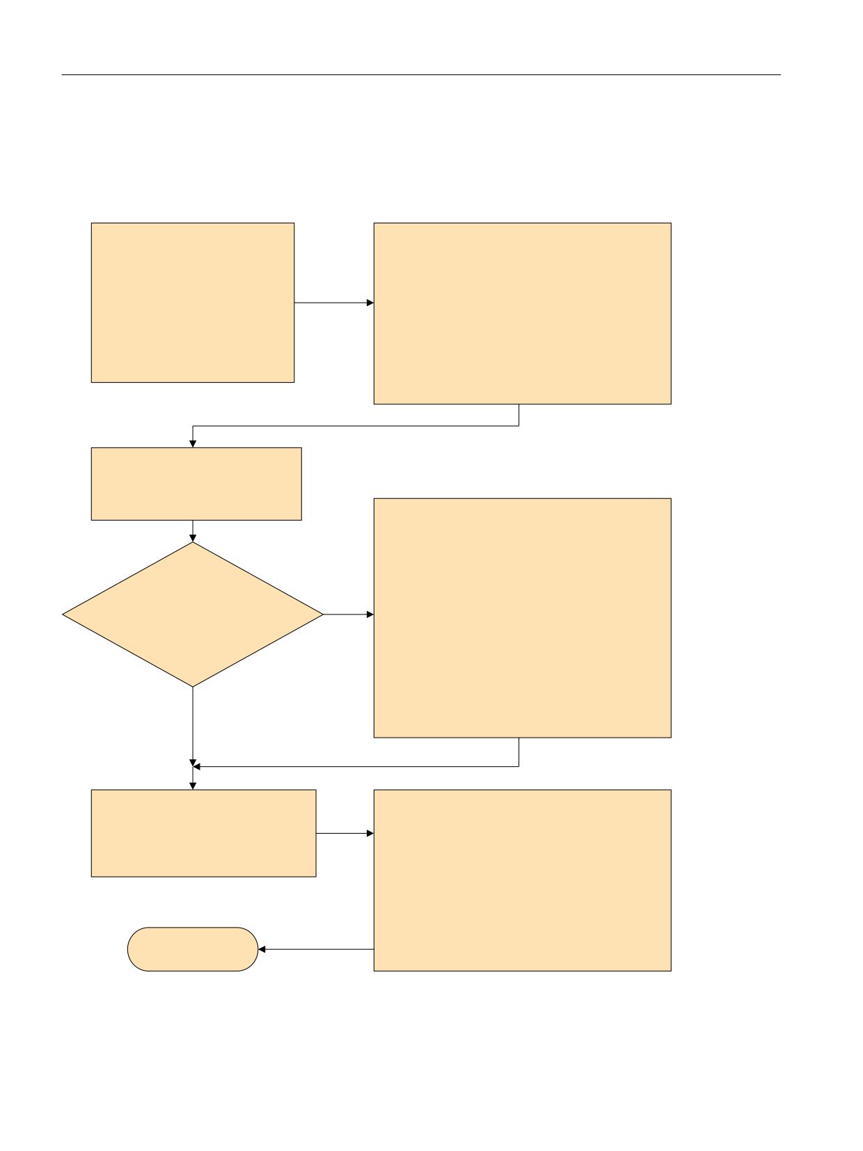
Technologies and cycles
18.11 Measuring cycles and measurement functions
CUST_MEACYC structogram
Sequence in the AUTOMATIC mode, using measure bore as example, CYCLE977 with probe
type 712.
6WUXFWXUH &<&/(
&867B0($&<&
,QSXW YDOXHV
B02'( JHQHUDWHG E\ PHDVXULQJ F\FOH
PHDVXULQJ YDULDQW
-XPS WR ODEHO
VSHFLILF VHWWLQJV
B0
EHIRUH ZRUNSLHFH PHDVXUHPHQW &<&/(
RIIVHW W\SH
XVHU VSHFLILF HQWULHV IRU H[DPSOH FRRODQW RII
RIIVHW WDUJHW
*272) B$0B:3B0(6
ಹ
VHWSRLQW
B$0B:3B0(6
PRQLWRULQJ SDUDPHWHUV
EHIRUH ZRUNSLHFH PHDVXUHPHQW
ಹ
0
SUHSDUDWLRQ RI PHDVXUHPHQW
FDOFXODWLRQV
SRVLWLRQ LQ IURQW RI WKH VW
PHDVXULQJ SRLQW
B02'( JHQHUDWHG E\ PHDVXULQJ F\FOH
-XPS WR ODEHO
B0($&<&B072))21
XVHU VSHFLILF 1& FRPPDQGV
WR GHDFWLYDWH WKH SUREH
IRU H[DPSOH 0 RU + FRPPDQGV
6'
\HV
ಹ
6&6B0($B)81&7,21B0$6. %LW
6326
SRVLWLRQ VSLQGOH
4XHULHG EHIRUH HDFK IXUWKHU
ಹ
GHILQHG E\ F\FOH
6326 ಹ
ಹ
B0($&<&B0721
XVHU VSHFLILF 1& FRPPDQGV
WR DFWLYDWH WKH SUREH
IRU H[DPSOH 0 RU + FRPPDQGV
QR
5(7
SURFHVV DOO RWKHU PHDVXULQJ SRLQWV
B02'( JHQHUDWHG E\ PHDVXULQJ F\FOH
FDOFXODWH PHDVXUHPHQW GLIIHUHQFH
-XPS WR ODEHO
FKHFN UHVXOW
B0(
DIWHU ZRUNSLHFH PHDVXUHPHQW &<&/(
H[HFXWH RIIVHW
XVHU VSHFLILF HQWULHV IRU H[DPSOH FRRODQW RQ
*272) B%0B:3B0(6
ಹ
B%0B:3B0(6
DIWHU ZRUNSLHFH PHDVXUHPHQW
(QG RI F\FOH
ಹ
0
Figure 18-17
Structure: CYCLE977 / CUST_MEACYC
SINUMERIK Operate
476
Commissioning Manual, 12/2019, 6FC5397-1DP40-6BA3
Technologies and cycles
18.11 Measuring cycles and measurement functions
Note
Commenting out spindle SPOS commands
If the spindle SPOS command is to be commented out in the CUST_MEACYC.SPF cycle, set
the cycle setting in SD55740 $SCS_MEA_FUNCTION_MASK to active with Bit 1 = 1.
You can see how to comment out a spindle SPOS command in the CUST_MEACYC.SPF cycle
in the following example:
Example
;
;*#1 Example application for spindle pre-positioning if there is no coupling
;*##1 between spindle and the coordinate system active!
;*#1 This example can be removed if necessary!
;*#2 User example for spindel positioning, if you do not have a coupling
;*##2 between the spindel and the coordinate system!
;*#2 If this lines are not necessary, the user can delete this example!
;
; cycle is calling from the AUTOMATIC-mode AND the spindel is positionable
IF NOT(_OVI[14]) AND NOT(_SPOS_MOD)
; no coupling between the spindel and the coordinate system!
; SD55740, Bit 1 = 0
IF ($SCS_MEA_FUNCTION_MASK B_AND 'B10')==0
; SPOS=0 ; <===== commented out
ENDIF
ENDIF
M17
;
18.11.3
Measuring in JOG mode
Requirements
You have already made the settings from the previous Chapter "Measuring cycles and
measurement functions, general (Page 472)".
SINUMERIK Operate
Commissioning Manual, 12/2019, 6FC5397-1DP40-6BA3
477

Technologies and cycles
18.11 Measuring cycles and measurement functions
Workpiece measurement
For milling:
● The probe has been inserted in the tool spindle.
● The probe has been selected in the tool list as type 7xx (probe).
● The probe is activated as tool in the current NC channel.
Tool measurement
To measure tools, an appropriate probe must be located in the machine space so that this can
be reliably and safely reached with a tool in the spindle.
The following tool types are supported with measure tool:
● Milling technology: Tool types 1xx and 2xx
● Turning technology: Tool types 5xx, 1xx and 2xx
For the specified tool types, the tool lengths and the tool radii can be measured.
Setting general data
SD54782 $SNS_J_MEA_FUNCTION_MASK_TOOL
Settings for the input screen, measuring
in JOG, tool measurement.
Bit 2 = 1
Activates the "Enable automatic tool measuring" function.
Bit 3 = 1
Selects the tool probe calibration data field, enable.
Bit 10 = 1
Selects the individual cutting edge measurement
Bit 11 = 1
Selects the spindle reversal when calibrating in the plane
MD51784 $MNS_J_MEA_T_PROBE_APPR_AX_DIR [i]
Measuring in JOG: Approach direction in the plane to the tool probe
-2
Negative direction, 2nd measuring axis
-1
Negative direction, 1st measuring axis (default setting)
0
Positive direction, 1st measuring axis
1
2
Positive direction, 2nd measuring axis
MD52750 $MCS_J_MEA_FIXPOINT
Z value for measurement with respect to a
fixed point
MD52751 $MCS_J_MEA_MAGN_GLAS_POS
Zoom-in position for tool measurement
[0]
Position in the 1st axis
[1]
Position in the 2nd axis
SINUMERIK Operate
478
Commissioning Manual, 12/2019, 6FC5397-1DP40-6BA3

Technologies and cycles
18.11 Measuring cycles and measurement functions
Checking and setting the general machine data
MD11450 $MN_SEARCH_RUN_MODE
"Search run" programming.
Bit 1 = 1
Automatic ASUB start after output of the action blocks (see also
MD11620 $MN_PROG_EVENT_NAME). Alarm 10208 is not output until the ASUB is
completed.
MD11604 $MN_ASUP_START_PRIO_LEVEL
Priorities from which ASUP_START_MASK is
effective.
= 1 - 64
Priorities for ASUP_START_MASK.
Setting channel-specific machine data
MD20050 $MC_AXCONF_GEOAX_ASIGN_TAB[ ]
Assignment, geometry axis to channel axis.
[0]
For measuring in JOG mode, all of the geometry axes must be available. Preferably XYZ.
[1]
[2]
MD20110 $MC_RESET_MODE_MASK
Defines the basic control settings after reset /
TP end,
= 4045H
Minimum value
Bit 0 = 1
Basic control setting after power on and reset.
Bit 2 = 1
Bit 6 = 1
Bit 14 = 1
MD20112 $MC_START_MODE_MASK
Definition of the basic control setting after part
program start.
= 400H
Minimum value
Bit 6 = 0
Definition of the basic control setting after NC start.
MD20310 $MC_TOOL_MANAGEMENT_MASK
Activates tool manager functions
= 4002H
Minimum value
Bit 1 = 1
Tool manager and monitoring functions active
Bit 14 = 1
Automatic tool change for RESET and Start.
MD28082 $MC_SYSTEM_FRAME_MASK
System frames (SRAM).
Bit 0 = 0
Do not setup system frames for actual value setting and scratching.
Bit 0 = 1
Setup system frames for actual value setting and scratching.
SINUMERIK Operate
Commissioning Manual, 12/2019, 6FC5397-1DP40-6BA3
479

Technologies and cycles
18.11 Measuring cycles and measurement functions
The following channel-specific machine data is only effective if the system frame actual value
setting and scratching is set up using the above mentioned machine data
MD28082 $MC_SYSTEM_FRAME_MASK, bit 0 = 0.
MD24006 $MC_CHSFRAME_RESET_MASK
Active system frames after reset.
Bit 0 = 1
Reset response of the system frames or actual value setting.
MD24007 $MC_CHSFRAME_RESET_CLEAR_MASK
Clear system frames at reset.
Bit 0 = 0
Clear response of the system frames on reset.
Note
If you create the conditions described in this section and you have set and checked the machine
setting data, then in JOG mode, you can measure a workpiece using a workpiece probe at a
milling machine!
In JOG mode, you can measure a tool using a tool probe at a milling machine or lathe!
A description is provided in the following chapters as to which settings you can make in order
to adapt measuring to the specific requirements of your particular machine.
18.11.3.1
Measuring workpieces at the milling machines
Measuring in the "Machine" operating area can be appropriately adapted to the specific
requirements using the following channel-specific general machine data and channel-specific
cycle setting data.
General configuration machine data
SD55630 $SCS_MEA_FEED_MEASURE
Measuring feedrate for workpiece meas-
urement in JOG and AUTOMATIC
300
Default value
Note
Measuring feedrate for workpiece measuring
All measuring cycles use the value saved in SD54611 as the measuring feedrate value
following calibration of the workpiece probe. A different measuring feedrate can be assigned for
each calibration field [n].
When calibrating the probe, either the measuring feedrate from SD55630
$SCS_MEA_FEED_MEASURE is used, or the measuring feedrate can be overwritten in the
input screen when calibrating. Bit 4 = 1 must be set in the
SD54760 $SNS_MEA_FUNCTION_MASK_PIECE for this purpose.
SINUMERIK Operate
480
Commissioning Manual, 12/2019, 6FC5397-1DP40-6BA3

Technologies and cycles
18.11 Measuring cycles and measurement functions
MD52207 $MCS_AXIS_USAGE_ATTRIB[n]
Attributes of the axes
[n] channel axis number
Bit 6
Request rotational axis as offset target for measuring
= 0
Default value
= 1
Rotary axis is displayed as offset target in the "Measuring in JOG" window
Bit 9
SPOS behavior of main spindle influenced in connection with measuring cycles
= 0
The positioning behavior of the tool spindle is not influenced
= 1
The measuring cycles do not position the tool spindle (no SPOS)
Note
If the tool spindle is never SPOS-capable, Bit 9 = 1 must be set.
MD51740 $MS_MEA_FUNCTION_MASK
Measuring cycles, workpiece- tool measure-
ment function screen
Bit 7
Workpiece, accept active into inactive WO, JOG mode only, set edge
= 0
In JOG mode, "Set edge" function with correction of the measuring result to an inactive work
offset (target frame), of the geometry axes in the target frame, only the measuring axis is
specified with the result
No values are adopted from the active work offset (source frame) for geometry axes which
have not been measured. (compatibility)
From all non-geometric axes (rotary and auxiliary axes), mirroring, rotations and translations
are adopted from the active work offset (source frame) into the selected inactive work offset
(target frame). (compatibility)
= 1
In JOG mode, "Set edge" function with correction of the measuring result to an inactive work
offset (target frame), the measuring axis is specified in the target frame with the measure-
ment result
For all other axes (geometry axes, rotary axes and auxiliary axes), mirroring, rotations and
translations are also adopted from the active work offset (source frame) into the selected
inactive work offset (target frame)
This description applies for automatic measuring with electronic sensor, and likewise for the
"scratching" function with processing tool, refer to Section "Measuring without electronic probe
in JOG (Page 489)".
MD51751 $MNS_J_MEA_M_DIST_MANUELL
Measurement path in mm, in front of and
behind the measurement point
= 10
Default value
MD51757 $MNS_J_MEA_COLL_MONIT_FEED
Position feedrate in mm/min, in the working
plane for active collision monitoring
= 1000
Default value
SINUMERIK Operate
Commissioning Manual, 12/2019, 6FC5397-1DP40-6BA3
481

Technologies and cycles
18.11 Measuring cycles and measurement functions
MD51758 $MNS_J_MEA_COLL_MONIT_POS_FEED
Position feedrate in mm/min, in the infeed
axis for active collision monitoring
= 1000
Default value
MD51770 $MNS_J_MEA_CAL_RING_DIAM[n]
Pre-assignment of the calibration ring diam-
eter in mm specifically for the calibration da-
ta sets
= -1
Default value
MD51772 $MNS_J_MEA_CAL_HEIGHT_FEEDAX[n]
Pre-assignment of the calibration height
in mm in the infeed axis, specifically for
the calibration data sets
= -99999
Default value
General cycle setting data
SD54780 $SNS_J_MEA_FUNCTION_MASK_PIECE
Configuration of the input screens for
measuring in the "Machine" operating
area in the JOG operating mode
= 512
Default value
Bit 2 = 1
Activates measurements with an electronic probe
Bit 3 = 1
Selects the probe calibration data, enable
Bit 6 = 1
Selects ZO correction in the basis reference (SETFRAME), enable
Bit 7 = 1
Selects ZO correction in channel-specific basic frames, enable
Bit 8 = 1
Selects ZO correction in the global basic frame, enable
Bit 9 = 1
Selects ZO correction in adjustable frames, enable
Bit 16 = 1
Selects workpiece measurement with spindle reversal
Bit 17 = 1
Selects align workpiece probe in the switching direction
Bit 28 = 1
Selects adjust workpiece length, enable
18.11.3.2
Measuring tools at the milling machines
Measuring feedrate for tool measurement in JOG and AUTOMATIC
SD55628 $SCS_MEA_TP_FEED_MEASURE
Calibrate measuring feedrate for tool
probe and measure tool with station-
ary spindle.
= 300
Default value
SINUMERIK Operate
482
Commissioning Manual, 12/2019, 6FC5397-1DP40-6BA3

Technologies and cycles
18.11 Measuring cycles and measurement functions
Note
Measuring feedrate for tool measuring
All measuring cycles use the value saved in SD54636 or SD54651 as the measuring feedrate
after the tool probe has been calibrated. A different measuring feedrate can be assigned for
each calibration field [n].
When calibrating the probe, either the measuring feedrate from
SD55628 SCS_MEA_TP_FEED_MEASURE is used, or the measuring feedrate can be
overwritten in the input screen when calibrating. To do this,
SD54762 $SNS_MEA_FUNCTION_MASK_TOOL bit 4 must be set to 1.
MD51757 $MNS_J_MEA_COLL_MONIT_FEED
Position feedrate in mm/min, in the working
plane for active collision monitoring
= 1000
Default value
MD51758 $MNS_J_MEA_COLL_MONIT_POS_FEED
Position feedrate in mm/min, in the infeed
axis for active collision monitoring
= 1000
Default value
In the following setting data, index [k] stands for the number of the current data field (probe
number -1) of the probe.
SD54633 $SNS_MEA_TP_TYPE[k]
Probe type, cube/disk
= 0
Compatibility (measuring cycles: cube, turning surface shows probe, milling surface shows
disk)
= 101
Disk in XY, working plane G17
= 201
Disk in ZX, working plane G18
= 301
Disk in YZ, working plane G19
= 2
Probe
= 3
Cube
The following setting data is used to define in which axes and directions it is possible to calibrate
a tool probe.
SD54632 $SNS_MEA_T_PROBE_ALLOW_AX_DIR[k]
Axes and directions for "calibration"
= 133
Default value
Decimal place
ONES
1st axis
= 0
axis not possible
= 1
only minus direction
= 2
only plus direction
= 3
both directions
TENS
2nd axis
SINUMERIK Operate
Commissioning Manual, 12/2019, 6FC5397-1DP40-6BA3
483

Technologies and cycles
18.11 Measuring cycles and measurement functions
Decimal place
= 0
axis not possible
= 1
only minus direction
= 2
only plus direction
= 3
both directions
HUNDREDS
3rd axis
= 0
axis not possible
= 1
only minus direction
= 2
only plus direction
= 3
both directions
Example
If the general setting data SD54632 $SNS_MEA_T_PROBE_ALLOW_AX_DIR[k] has the value
123, the tool probe is calibrated as follows in the G17 plane:
● X in both directions
● Y only in plus direction
● Z only in minus direction
SD54631 $MNS_MEA_T_PROBE_DIAM_LENGTH[k]
Effective diameter of the tool probe
for length measurement.
= 0
Default value
General cycle machine/setting data for tool probe
MD51780 $MNS_J_MEA_T_PROBE_DIAM_RAD[k]
Effective diameter of the tool probe
for radius measurement.
= 0
Default value
SD54634 $SNS_MEA_TP_CAL_MEASURE_DEPTH[n]
Distance between the tool probe up-
per edge and the milling tool lower
edge.
= 2
Default value
MD51752 $MNS_J_MEA_M_DIST_TOOL_LENGTH
Measuring path to measure the tool
length.
= 2
Default value
MD51753 $MNS_J_MEA_M_DIST_TOOL_RADIUS
Measuring path to measure the tool ra-
dius.
= 1
Default value
SINUMERIK Operate
484
Commissioning Manual, 12/2019, 6FC5397-1DP40-6BA3