SINUMERIK 840D sl. Basesoftware and operating software. Manual (2019) - page 3
Customizing the "Machine" operating area
8.11 User status display (OEM)
Configuration
The user icons are configured in the slmahdconfig.ini file in Section [UserIcons]. The
following data is required:
● The start address of the PLC double word with the bits to control the display of the user icons.
● For each bit used, the file name of the icon and the position at which the icon should be
displayed.
Alternatively, you can use the following parameters for the definition:
● USER_ICON_BASE
This means that 32 bits are available with UI_0 (highest bit) to UI_31 (lowest bit).
Example: USER_ICON_BASE=DB80.DBB0
⇒ UI_0 = DB80DBX3.0 and UI_31 = DB80.DBX0.7
● USER_ICON_BASE256
This means that 256 bits are available with UI_0 (highest bit) to UI_255 (lowest bit).
Example: USER_ICON_BASE256=DB19.DBB80
⇒ UI_0 = DB19.DBX111.0 and UI_255 = DB19.DBX80.7
Example
[UserIcons]
USER_ICON_BASE=DB19.DBB80
; set the start byte of the PLC double word that displays the icons (DB19.DBD80)
UI_0 = icon1.png,4
; show icon1.png on position 4 if bit 0 (DB19.DBX83.0) is set
UI_1 = icon2.png,6
; show icon2.png on position 6 if bit 1 (DB19.DBX83.1) is set
Offset
With a non-unique selection (bits for multiple identifiers whose image is to be displayed at the
same position):
The image with the lower identifier number is superimposed with the image with the higher
identifier number for the same position. Non-unique selection can also be used with less than
16 active selection bits. The PLC can deliberately use this superimposition to overlay less
important displays (with lower identifier numbers) with important displays (high identifier
numbers).
Note
If two HMI applications are assigned to one NC/PLC unit (M:N), the PLC must first determine
from the interface which of the HMI interfaces is active. Icons can be requested by the PLC for
the active HMI application only.
SINUMERIK Operate
140
Commissioning Manual, 12/2019, 6FC5397-1DP40-6BA3
Customizing the "Machine" operating area
8.13 Activate machining time recording
Possible applications
With a unique selection, a maximum of 16 bits are set simultaneously in the four selection bytes
for each of the different positions.
●
32 alternative images for a position, each selected with a different bit (currently only one
active selection bit)
● Two alternative images for each of the permissible 16 positions, each position requires two
of the 32 selection bits (maximum 16 active selection bits at any one time)
● Combination thereof with a maximum total of 32 images for the maximum 16 positions
(maximum of 16 active selection bits at any one time)
● More than 16 selection bits.
8.12
Configuring the offset display
Configuring the screen display
Overrides resulting from handwheel offsets (DRF) or tool length corrections from the value of
system variable $AA_TOFF can be directly displayed on the screen.
The screen display for the override is configured using the following channel-specific machine
data:
MD52210 $MCS_FUNCTION_MASK_DISP
Function screen display
Bit 14
Display DRF offset under Machine
Bit 15
Display tool offset ($AA_TOFF) under Machine
8.13
Activate machining time recording
If you want to record and store the machining time in Automatic mode, you can make the
settings on the user interface.
Additional information
Additional information about the setting is provided in the
Operating Manual Universal/Turning/Milling/Grinding
Activating the time recording
To use the function, the following channel machine data must be so set in all channels, even if
the machining time recording is not activated for all channels:
MD18370 $MN_MM_PROTOC_NUM_FILES[1]
Maximum number of log files
= 2
For OEM applications
SINUMERIK Operate
Commissioning Manual, 12/2019, 6FC5397-1DP40-6BA3
141

Customizing the "Machine" operating area
8.13 Activate machining time recording
MD18371 $MN_MM_PROTOC_NUM_ETPD_STD_LIST[1]
Number of standard ETPD data lists
= 6
Number of standard data lists in the OPI module ETPD that are needed for Trace system
functions.
MD28300 $MC_MM_PROTOC_USER_ACTIVE[1]
Activate logging for one user
= 1
For system functions
MD28302 $MC_MM_PROTOC_NUM_ETP_STD_TYP[1]
Number of ETP standard event types
= 5
Number of standard event types in the OPI module ETP that are needed
Note
Machine data MD18370, MD18371 and MD28302 are still valid for recording machining time
when they are assigned higher values.
SINUMERIK Operate
142
Commissioning Manual, 12/2019, 6FC5397-1DP40-6BA3
Simulation and simultaneous recording
9
9.1
Simulation overview
Software option
You require the "3D simulation 1 (finished part)" option
for the 3D representation of the simulation.
Simulation is supported with its own program interpreter (SNCK) and a separate simulation-
data environment in SINUMERIK Operate. The SNCK considers the complete syntax of the
SINUMERIK control family, including the possibility of incorporating special user options on the
machine by comparing data with the NC environment. The simulation data can be matched
statically as required with the NC environment (initialization data, macros, user data, tool data,
machining cycles) or also dynamically when tool data or machining cycles are changed.
Machining simulations, with emphasis on the drilling, milling, turning and grinding technologies,
can be performed in the workpiece coordinate system for certain machine kinematics on the
user interface of the controller:
● The simulation of the finished part is performed with the real NC data.
● The NC data is automatically compared at each change of the part program.
● The simulation allows a dynamic representation of the machining, even for active 5-axis
transformation (TRAORI) and swiveled planes.
● Turning on milling machines.
● Simulation of a machining channel for conventional milling machines.
● Simulation of up to four machining channels for turning machines with B axis.
● Intelligent determination of the block times and the program execution time.
● Very fast graphical representation through the continuous refinement of the workpiece.
● Optimum resolution for each selected picture area.
● Any sections are possible.
● In parallel to the machining of one workpiece, the machining of another workpiece can be
simulated (as of NCU 720.x).
● 3D representation of simulation (option).
General conditions for the simulation
● Very fast simulation result, this means, however, low dynamic resolution.
● For complex representations, fine recording is too slow or does not run for very complex
parts.
● "Quickview" for mold-making part programs.
● The simulation cannot be used for compile cycles with special kinematics.
SINUMERIK Operate
Commissioning Manual, 12/2019, 6FC5397-1DP40-6BA3
143
Simulation and simultaneous recording
9.1 Simulation overview
●
Compile cycles are supported only to a limited extent.
●
Blank CAD data cannot be imported (for example, for castings).
●
Couplings cannot be simulated. (coupled motion, axial master-value coupling, electronic
gearbox):
- Coupled motion: TRAILON(<following axis>, <leading axis>, <coupling factor>)
- Axial master-value coupling: LEADON(Faxis, LAxis, curve table n) actual value and
setpoint coupling
- Electronic gearbox: EGDEF(FA, LA1, coupl.1, LA2, coupl.2, ... LA5, coupl.5), EGON,
EGONSYN, EGONSYNE
●
Reference point approach G74 is not operative during simulation.
●
The following is not supported:
- Axis container
- Dependencies on part programs and PLC
- Multiple clamping
- CNC function Synchronized actions for safe programmable logic (SPL) in the NC
●
Different technologies in different channels with different axis coordinate systems are not
fully supported.
●
A 3D simulation is not possible for the grinding technology.
●
The software limit switches are not evaluated:
In a manufacturer cycle for the tool replacement, the "Software limit switch + the Z axis"
machine data is used as replacement position:
G0 Z=$MA_POS_LIMIT_PLUS[Z]-0.1
This position is not used in the simulation, however, but rather the default setting for the
machine data = 1e8 = 100.000.000. This specified position is traversed in the simulation.
This makes the simulation very slow and causes the machining time to explode, e.g. 555
hours rather than 2 minutes.
●
Program start in the simulation:
If MD22622 $MCS_DISABLE_PLC_START is set in a channel, then the channel is not
automatically started in the simulation. It can then only be started from another channel
using the part program command "START". This function is not available for the
SINUMERIK 828D.
●
Alarm display in the simulation:
Alarms are output in the simulation exactly the same way as alarms in the normal program
execution, but no more than five alarms are displayed (above the graphic, to distinguish
them from the machine alarms).
If a different error signaling behavior (e.g. syntax error) occurs between simultaneous
recording and simulation, then, for example, the reason can be due to the hardware access
operations in the programming. The simulation does not access the hardware, however,
internally it reads the input with 0 and is then exited. On the other hand, for simultaneous
recording, an alarm is output.
SINUMERIK Operate
144
Commissioning Manual, 12/2019, 6FC5397-1DP40-6BA3
Simulation and simultaneous recording
9.2 Setting the technology for simulation
9.2
Setting the technology for simulation
Turning technology
Examples of machine kinematics:
● Conventional turning with two geometry axes
● Three spindles: Main spindle, counterspindle, tool spindle
● Counterspindle slides, tailstock as NC axis
● B axis: Aligning turning tools in the tool spindle
● Milling with geometry axes: TRANSMIT, TRACYL, TRAANG
Machine data for the turning technology:
MD52200 $MCS_TECHNOLOGY = 1
Turning technology
MD52000 $MCS_DISP_COORDINATE_SYSTEM = 34
Position of the coordinate system (exam-
ple)
Milling technology
Examples of machine kinematics:
● Milling with five axes: Swivel/TRAORI
● Swivel head change
Machine data for the milling technology:
MD52200 $MCS_TECHNOLOGY = 2
Milling technology
MD52000 $MCS_DISP_COORDINATE_SYSTEM = 0
Position of the coordinate system (example)
Grinding technology
Machine data for the grinding technology:
MD52200 $MCS_TECHNOLOGY = 3
Cylindrical grinding technology
MD52200 $MCS_TECHNOLOGY = 4
Surface grinding technology
MD52000 $MCS_DISP_COORDINATE_SYSTEM = 0
Cylindrical grinding and surface grinding
with moving column (example)
MD52000 $MCS_DISP_COORDINATE_SYSTEM = 6
Surface grinding with table machine (exam-
ple)
Meaning of the axes
MD52206 $MCS_AXIS_USAGE[n]
Meaning of the axes in the channel
[n] channel axis number
= 0
No special meaning
= 1
Tool spindle (rotating tool)
SINUMERIK Operate
Commissioning Manual, 12/2019, 6FC5397-1DP40-6BA3
145
Simulation and simultaneous recording
9.2 Setting the technology for simulation
= 2
Auxiliary spindle (rotating tool)
= 3
Main spindle (turning)
= 4
C axis of the main spindle (turning)
= 5
Counterspindle (turning)
= 6
C axis of the counterspindle (turning)
= 7
Linear axis of the counterspindle (turning)
= 8
Tailstock (turning)
= 9
Back rest (turning)
Note
To prevent errors occurring, the same axis must be defined as main or counterspindle for all
channels.
Enter the direction of rotation for the rotary axes that are not configured in a tool holder or a 5-
axis transformation via the following channel-specific machine data.
MD52207 $MCS_AXIS_USAGE_ATTRIB[n]
Attributes of the axes
[n] channel axis number
Bit 0
Rotates around 1st Geometry axis (for rotation axes)
Bit 1
Rotates around 2nd Geometry axis (for rotation axes)
Bit 2
Rotates around 3rd Geometry axis (for rotation axes)
Bit 3
Reversal of direction of rotation (for rotary axes)
The MD52290 $MCS_SIM_DISPLAY_CONFIG machine data acts only on the OP019. It has
no significance for SINUMERIK 828D.
MD52290 $MCS_SIM_DISPLAY_CONFIG
Position of the status display of the channel in the
simulation.
Bit 0
Upper left-hand corner
Bit 1
Upper right-hand corner
Bit 2
Lower left-hand corner
Bit 3
Lower right-hand corner
In the channel-specific machine data, for at least one geometry axis per channel, enter a value
other than 0.0, e.g. 0.001. If the value is 0.0, the system assumes that this parameter has still
not been set.
MD53230 $MCS_SIM_START_POSITION
Axis position when starting the simulation
Simulation is only possible if a value not equal to 0 has been set for at least one geometry axis.
Deactivating simulation
The following machine data must be set to deactivate the simulation:
MD51226 $MNS_FUNCTION_MASK_SIM
Simulation function screen
Bit 1 = 1
Deactivating simulation
Bit 10 = 1
Hide zero point symbol
SINUMERIK Operate
146
Commissioning Manual, 12/2019, 6FC5397-1DP40-6BA3
Simulation and simultaneous recording
9.3 Simultaneous recording overview
Simulation from kinematic chain
The following machine data must be set to use the simulation from kinematic chains:
MD51226 $MNS_FUNCTION_MASK_SIM
Simulation function screen
Bit 22
Machine model for simulation from kinematic chain (also without collision avoidance)
Tool change time
The following machine data defines the estimated time for a tool change in the simulation:
MD10190 $MN_TOOL_CHANGE_TIME
Tool change times for simulation
= 0
Seconds (default value 0)
The value only replaces times that are principally not incurred for a simulated tool change, e.g.
wait times for PLC commands (M206).
Traversing commands are added to the calculated time for the duration of the simulation if the
commands are included in the tool change cycle.
Add the following example to the programming in the tool change cycle, which means that the
value from MD10190 can be incorporated as total tool change time in the estimated simulation
time:
IF $MN_SIM_ENVIRONMENT B_AND 'B100'
M206 ; see MD 22560 $MC_TOOL_CHANGE_M_CODE
RET
ENDIF
9.3
Simultaneous recording overview
Software option
You require the option "Simultaneous recording (real-time simulation)"
for the "Simultaneous recording" function.
Software option
You require the "ShopMill/ShopTurn" option to
display the tailstock
Software option
You require the "3D simulation 1 (finished part)" option
for the 3D representation of the simultaneous recording function.
SINUMERIK Operate
Commissioning Manual, 12/2019, 6FC5397-1DP40-6BA3
147

Simulation and simultaneous recording
9.3 Simultaneous recording overview
During machining, the tool paths can be simultaneously recorded on the display of the
controller in a three-side view or 3D view. Workpiece graphics and views correspond to the
graphic simulation.
Note
To prevent an incomplete representation, you must activate the simultaneous recording prior
to the NC start.
Example: Activating the tailstock representation in the spindle chuck data
Procedure:
1. Make the tailstock visible by making the selection in the program.
2. Specify the tailstock dimensions:
Select in the operating area "Parameters" → "Setting data" → "Spindle chuck data", and
enter the "ZR" and "XR" parameters for the tailstock length and tailstock diameter.
The tailstock dimensions are written into the following machine data:
MD52218 $MCS_FUNCTION_MASK_TURN
Turning function screen
Bit 2 = 1
Tailstock enable:
The tailstock becomes visible if selected in the "tailstock" program.
MD53240 $MAS_ SPINDLE_PARAMETER[i]
Spindle chuck data in mm
[0]: Chuck dimension
[1]: Stop dimension
[2]: Jaw dimensions
MD53241 $MAS_ SPINDLE_CHUCK_TYPE
Spindle jaw type
0 = clamp from the outside
1 = clamp from the inside
MD53242 $MAS_TAILSTOCK_PARAMETER[i]
Tailstock data in mm
[0]: Tailstock dimension
[1]: Tailstock length
Activating the machining time display
Timers are provided as system variables in the Program runtime function. While the NC-
specific timers are always activated (for time measurements since the last controller power-up),
the channel-specific timers must be started via the following channel-specific machine data.
MD27860 $MC_PROCESSTIMER_MODE
Activate the program runtime measurement.
Bit 0 = 1
The measurement of the total runtime for all part programs is active
($AC_OPERATING_TIME).
Bit 1 = 1
The measurement of the actual program runtime is active
($AC_CYCLE_TIME).
SINUMERIK Operate
148
Commissioning Manual, 12/2019, 6FC5397-1DP40-6BA3

Simulation and simultaneous recording
9.4 Clamping a blank
Bit 4 = 1
Measurement also during active dry run feedrate.
Bit 5 = 1
Measurement also during program test.
9.4
Clamping a blank
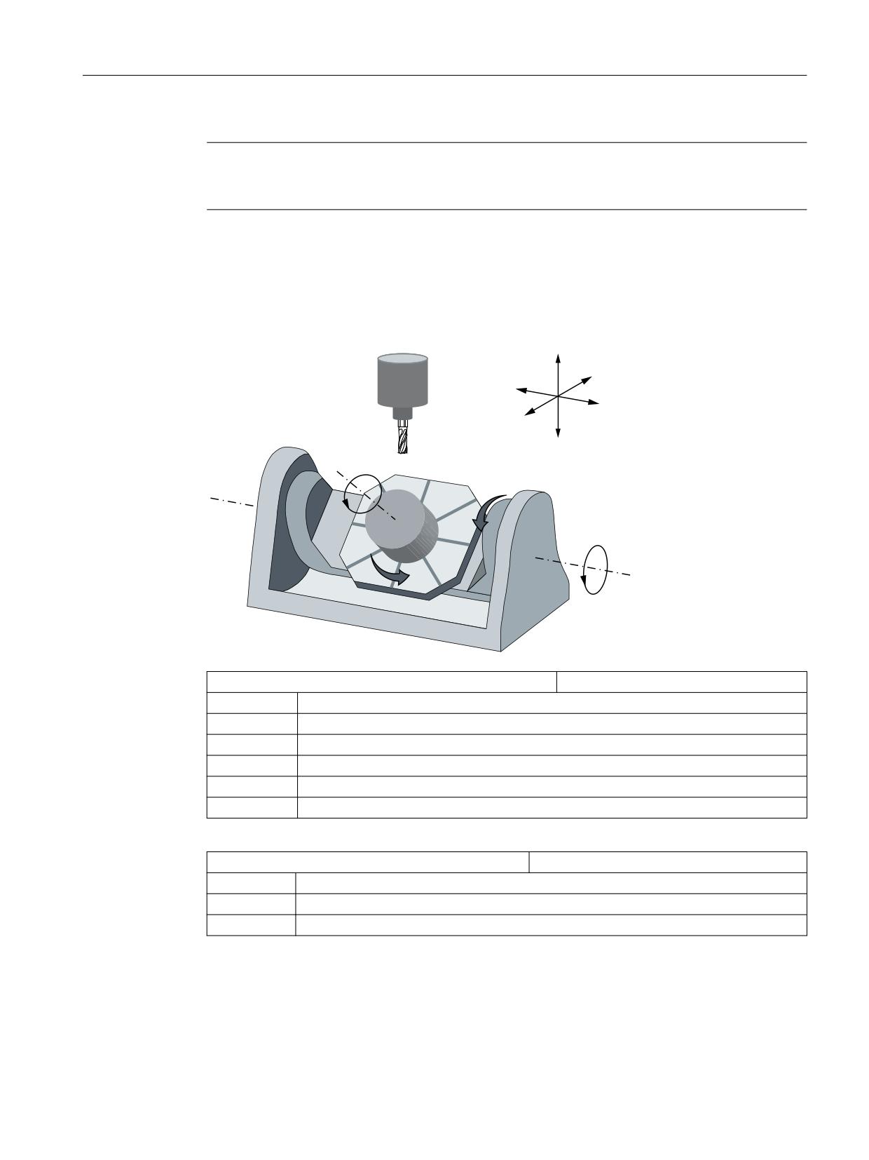
The blank clamping function allows you to select and specify in more detail the clamping
location for the blank.
You require this function if your machine satisfies one or more of the following requirements:
Requirements
● The machine has several clamping options available for selection.
● The machine has a clamping option that does not point in the Z direction as standard (e.g.
a boring mill).
Under the following circumstances, you can specify the position and orientation of the rotary
axes in the machine data MD53220 and MD52207:
● The position and orientation of the rotary axis is offset against the MCS zero point, but not
specified by a tool holder or a TRAORI.
● In a turning machine, the reference points of the main spindle or counterspindle are offset
against the MCS zero point in X or Z.
● The counterspindle cannot be traversed with a saddle, but rather is at a fixed position.
In order that for simulation / simultaneous recording, the rotary axes are displayed at the correct
location, their positions in the machine coordinate system must be specified using the following
machine data:
MD53220 $MAS_AXIS_MCS_POSITION[n]
Position of the axis in the MCS
[n] 0 = X, 1 = Y, 2 = Z
Additional information about the transformation of a rotary axis is provided in Chapter
"Technologies and cycles (Page 353)".
Function
Set the following channel-specific machine data:
MD52207 $MCS_AXIS_USAGE_ATTRIB[n]
Attribute of the axes in the channel
[n] channel axis number
Bit 0
Rotates around 1st Geometry axis (for rotation axes)
Bit 1
Rotates around 2nd Geometry axis (for rotation axes)
Bit 2
Rotates around 3rd Geometry axis (for rotation axes)
Bit 8
Lists rotary axis for blank clamping (on milling machines)
Bit 13
Position of the axis for blank selection from active work offset (with rotary axes)
SINUMERIK Operate
Commissioning Manual, 12/2019, 6FC5397-1DP40-6BA3
149
Simulation and simultaneous recording
9.4 Clamping a blank
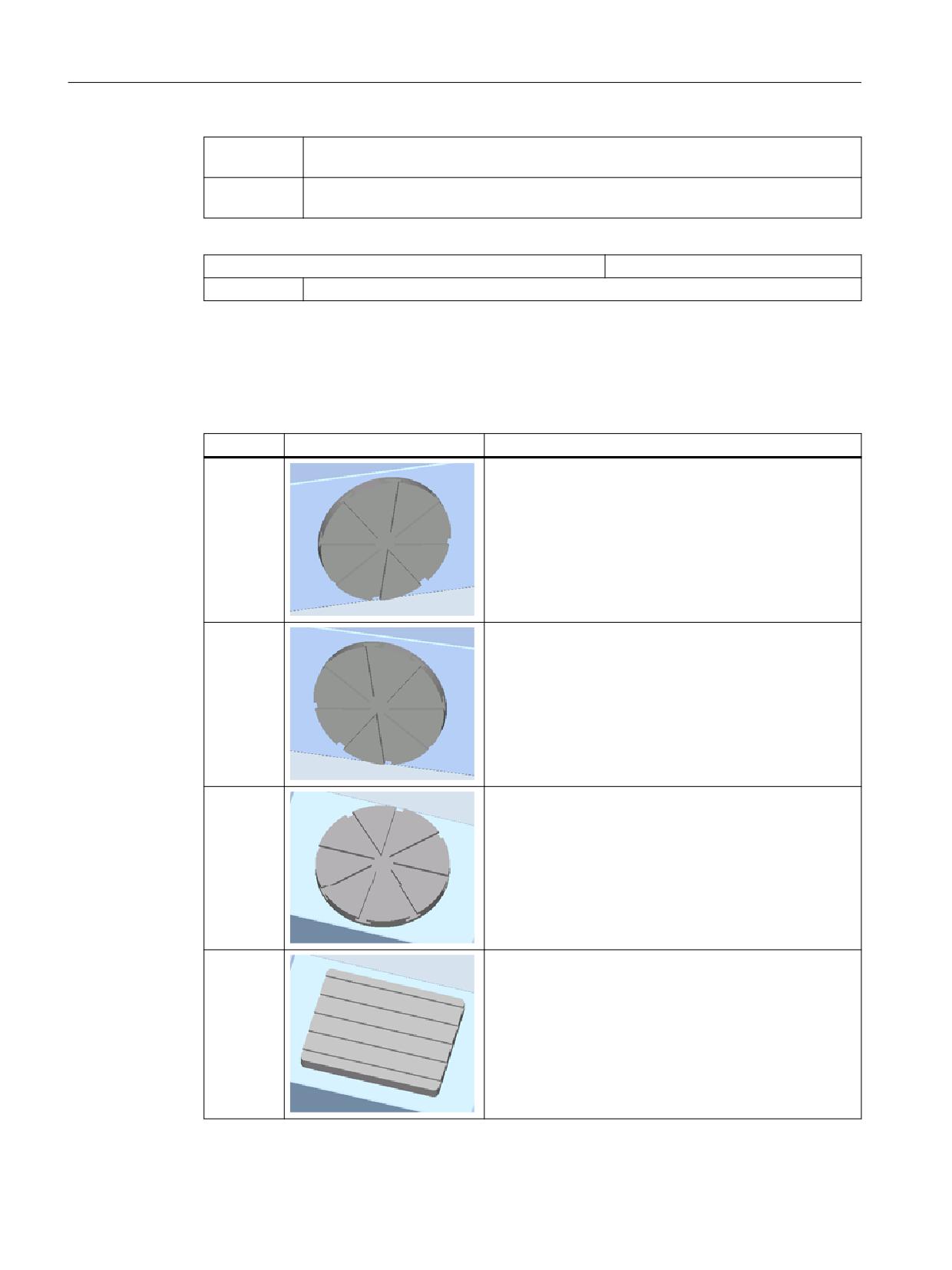
= 0
When simulation or simultaneous recording are started, the mountable rotary axis is
moved to the position from MD53220.
= 1
With a blank command, The mountable rotary axis is moved into the zero point of the
currently active work offset.
MD52214 $MCS_FUNCTION_MASK_MILL
Milling function screen
Bit 1
Offer fixed table for blank clamping (on milling machines)
Take the machine configuration for MD20080 from the example.
Function options
In the program header, a blank can be optionally set to A, B, C and table clamping:
Clamping
View
Machine data
A axis
MD52207 $MCS_AXIS_USAGE_ATTRIB bit 0 and
bit 8 = 1
B axis
MD52207 $MCS_AXIS_USAGE_ATTRIB bit 1 and
bit 8 = 1
C axis
MD52207 $MCS_AXIS_USAGE_ATTRIB bit 2 and
bit 8 = 1
Table
MD52214 $MCS_FUNCTION_MASK_MILL bit 1 = 1
SINUMERIK Operate
150
Commissioning Manual, 12/2019, 6FC5397-1DP40-6BA3
Simulation and simultaneous recording
9.4 Clamping a blank
Note
To obtain the selection option in the program header, two rotary axes must be defined for the
raw part clamping.
Example for the machine configuration
Example for a machine configuration when the A axis should rotate at the X axis:
63
=
<
;
&
$
MD20080 $MC_AXCONF_CHANAX_NAME_TAB[n]
Channel axis name in channel [n]
[0]
X
[1]
Y
[2]
Z
[3]
Spindle
[4]
A
[5]
C
MD52207 $MCS_AXIS_USAGE_ATTRIB[4]
Attribute of rotary axis A
= 181H
Bit 0 = 1
Rotates around 1st Geometry axis (for rotation axes)
Bit 8 = 1
Lists rotary axis for blank clamping (on milling machines)
Additional information
Additional information about setting ShopMill is provided in the
Operating Manual Milling
SINUMERIK Operate
Commissioning Manual, 12/2019, 6FC5397-1DP40-6BA3
151
Simulation and simultaneous recording
9.4 Clamping a blank
SINUMERIK Operate
152
Commissioning Manual, 12/2019, 6FC5397-1DP40-6BA3
Spindle functions
10
10.1
Spindle control
You can select from the following spindle control settings:
End of program
The following M functions are used for the end of program:
M function from
Main program end
Spindle continues
MD10714 $MN_M_NO_FCT_EOP
to run
M2, M30
End of main program and return jump to
Spindle stops
beginning of program
M17
End of subprogram and return jump into
Spindle continues
the main program
to run
If machine data MD10714 $MN_M_NO_FCT_EOP is not equal to zero, then a distinction is
made between M2 / M30 (program end of an NC program) and the M function set in
MD10714 $MN_M_NO_FCT_EOP.
Example
MD10714 $MN_M_NO_FCT_EOP = 32 means "M32" for the program end of a program
generated in the "JOG" or "MDA" operating mode.
Among other things, this functionality is required in order to continuously start the spindle in
manual operation (e.g. for scratching).
Configuring keys
If you implement a manual control using the keys on the machine control panel, then this is
realized via the following interface signals in the spindle data block:
DB3x.DBX30.0
Spindle stop
DB3x.DBX30.1
Spindle start, clockwise rotation
DB3x.DBX30.2
Spindle start, counter-clockwise rotation
The spindle can be started and stopped in the following state:
DB21.DBX35.7= 1
Channel in reset state
DB21.DBX35.6 = 1
Channel state interrupted
DB21.DBX35.3 = 1
Program state interrupted
SINUMERIK Operate
Commissioning Manual, 12/2019, 6FC5397-1DP40-6BA3
153
Spindle functions
10.2 Analog spindle
Note
If the spindle must be stopped when the program is running, then set the interface signal
DB3x.DBX4.3, "Feed stop/spindle stop" in the user PLC.
Additional settings:
MD11450 $MN_SEARCH_RUN_MODE
Search run parameterization
Bit 1 = 1
Automatic ASUB start after output of the action blocks (see also
MD11620 $MN_PROG_EVENT_NAME). Alarm 10208 is not output until the ASUB is
completed.
Additional information
A detailed description on how to configure the spindle, is provided in the
Function Manual Axes and Spindles
Direction of rotation (only for ShopTurn)
In the ShopTurn user interface, ensure that the direction of rotation of the spindle and C axis is
correctly displayed and when programming ShopTurn functions, that the correct direction of
rotation is executed. You must base these settings on the actual direction of rotation of the
spindle / C axis on the machine.
● If you use the functions cylinder surface transformation and face machining, then a
precondition is that the function was correctly commissioned.
See Cylinder surface transformation (TRACYL) (Page 394)
● The direction of rotation of the spindle / C axis for the M function M3 that is displayed in the
ShopTurn interface is defined in part using machine data:
See: Defining the direction of rotation in Section: Setting-up ShopTurn cycles for turning
(Page 383)
● The direction of spindle rotation (M3 / M4) is assigned to the positive rotational direction of
the C axis via interface signal DB31, ... DBX17.6. The bit defines whether M3 and C+ rotate
in the same direction (= 0) or in opposite directions (= 1). The corresponding setting options
can be found in the following sections:
- Direction of rotation of counter-spindle Setting up the counterspindle under ShopTurn
(Page 388)
- Direction of rotation of main spindle Setting-up ShopTurn cycles for turning (Page 383)
10.2
Analog spindle
Machine axis index for analog spindle
For a spindle which is not assigned to any drive (FDD, MSD), the utilization display can be
controlled via a PLC.
SINUMERIK Operate
154
Commissioning Manual, 12/2019, 6FC5397-1DP40-6BA3
Spindle functions
10.3 Spindle diagnostics
In order that the operating software identifies the spindle as analog spindle, enter the axis index
of the analog spindle in the following machine data:
MD51068 $MNS_SPIND_DRIVELOAD_FROM_PLC1
Machine axis index spindle 1
Utilization display from the PLC
Machine axis index of a spindle (analog) that draws the data for the utilization display in the
T,F,S window from the PLC (DB19.DBB6).
MD51069 $MNS_SPIND_DRIVELOAD_FROM_PLC2
Machine axis index spindle 2
Utilization display from the PLC
Machine axis index of a spindle (analog) that draws the data for the utilization display in the
T,F,S window from the PLC (DB19.DBB7).
10.3
Spindle diagnostics
10.3.1
Spindle diagnostics
Software option
For the "Spindle diagnostics" you require the "S-Monitor" option.
Main spindle drives are monitored via various status signals. The DRIVE-CLiQ connection at
the spindle can be used to evaluate these signals in the drive. The status signals are evaluated
for more effective diagnostics of the spindle operating states. The following information is
displayed on the user interface with the aid of the "S-Monitor" software option:
● Operating hours
● Temperatures
● Speed/torque
● Clamping system
● Logistics data
Requirements
● A spindle with DQI encoder: r0459, bit 14 = 1.
● Drive telegram 139 is configured for the spindle.
● The spindle functionality for the machine axis is present when MD35000
$MA_SPIND_ASSIGN_TO_MACHAX > 0
The value corresponds to the spindle number.
References
For further information, please refer to the following documentation:
SINUMERIK Operate
Commissioning Manual, 12/2019, 6FC5397-1DP40-6BA3
155

Spindle functions
10.3 Spindle diagnostics
Basic Functions Function Manual: Spindles (S1)
Section "Spindle with SMI 24 (Weiss spindle)"
Data overview
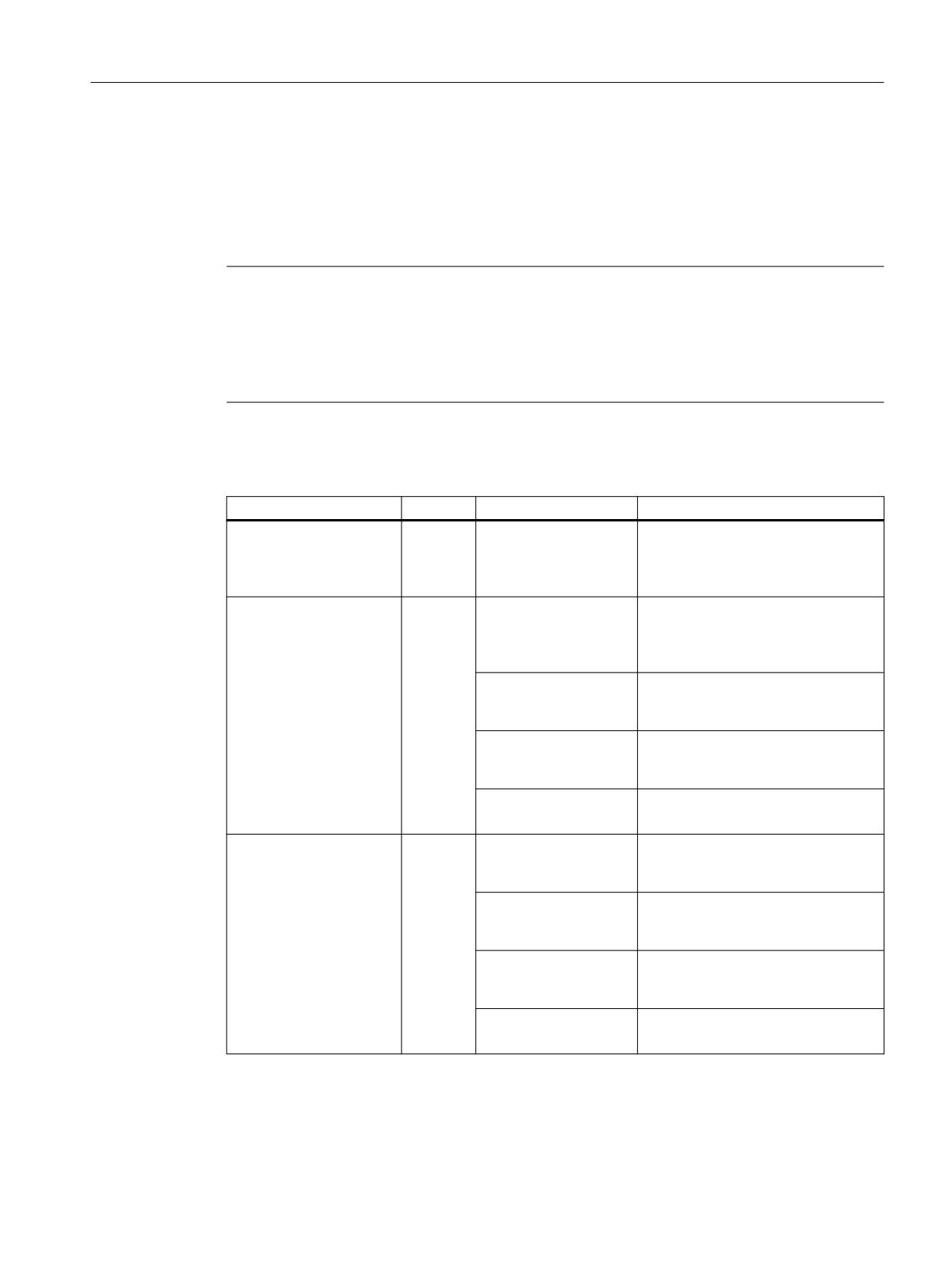
The "S1 Spindle Diagnostics" window shows the following information:
Parameter
Value
Operating hours
h
● Spindle under control
● Spindle under speed
Number of clamping cycles (tool change)
Definition of a clamping cycle: Released clamping state [3] → Clamped clamping state
[7, 8 or 10] → Released clamping state [3].
Motor temperature
°C
Clamping state (sensor 1)
V
Piston free (sensor 4)
E.g. defined rotary angular position of the shaft (sensor 5)
Yes/No
Maximum speed
rpm
Procedure
1. Select the "Diagnostics" operating area.
2. Press the menu forward key.
3. Press the "Spindle diagostics" softkey to obtain a data overview.
The "S1 Spindle Diagnostics" window opens.
Note
If several spindles are in operation, select the desired spindle using the "Spindle +" or "Spindle
-" softkey.
See also
Tool change with hybrid spindle from the company Weiss (https://
support.industry.siemens.com/cs/ww/en/view/109475707)
SINUMERIK Operate
156
Commissioning Manual, 12/2019, 6FC5397-1DP40-6BA3
Spindle functions
10.3 Spindle diagnostics
10.3.2
Temperatures
Which temperatures are evaluated and displayed depends on the number and the mounting
location (e.g. for sensor S6, bearing temperature front) of the sensors installed in the spindle.
The motor temperature is not displayed when the temperature sensor sensor type parameter
p0601 = 0 or 1.
Note
Temperature limits
The limit values displayed here refer to the spindle monitoring and have no effect on the drive
parameter values set in the drive that apply for the shutdown response of the spindle. The
temperature limit values are preset in the SMI24 and cannot be changed in this window. If
necessary, you must adapt the shutdown limit values for the drive.
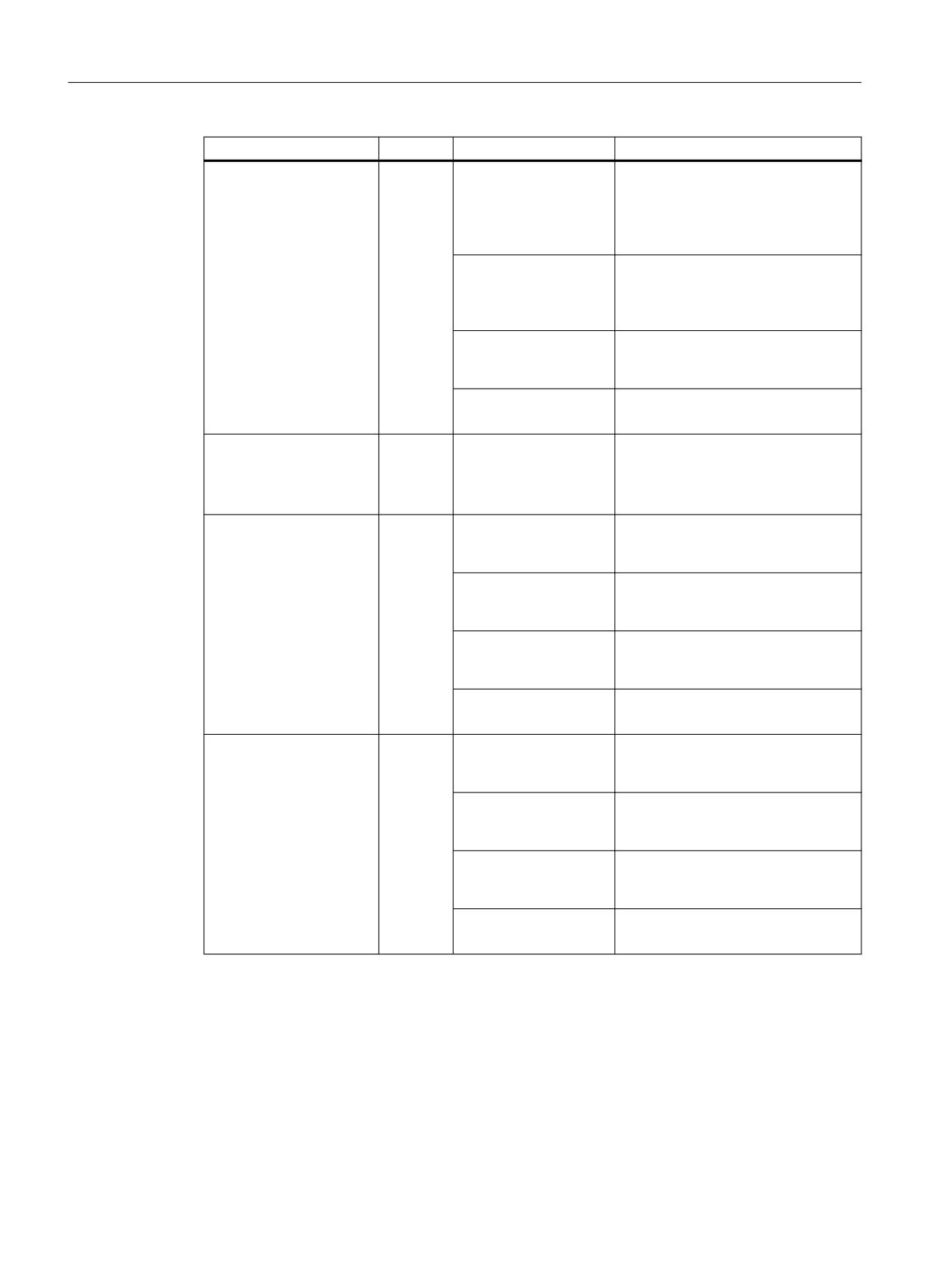
Up to three temperatures can be evaluated:
Signal
Sensor
Column/meaning
Description
Motor temperature
KTY
Actual
Current motor temperature. If an
(Page 159)
overtemperature protection is
present and responds, the value 250°
C is displayed.
Motor temperature
Limit
Stored threshold for motor overtem-
perature as of which an alarm is is-
Alarm
sued due to KTY motor overtemper-
ature.
Duration of the upper
Displays the accumulated hours dur-
limit violation
ing which an upper limit violation was
present.
Last upper limit viola-
Displays the time stamp [date] and
tion
[time] at which the last upper limit vi-
olation was present.
Number of
Accumulated number of upper limit
violations.
upper limit violations
Motor temperature
Limit
Stored threshold for motor overtem-
perature as of which a fault is issued
Fault
due to KTY motor overtemperature.
Duration of the upper
Displays the accumulated hours dur-
limit violation
ing which an upper limit violation was
present.
Last upper limit viola-
Displays the time stamp [date] and
tion
[time] at which the last upper limit vi-
olation was present.
Number of
Accumulated number of upper limit
violations.
upper limit violations
SINUMERIK Operate
Commissioning Manual, 12/2019, 6FC5397-1DP40-6BA3
157
Spindle functions
10.3 Spindle diagnostics
Signal
Sensor
Column/meaning
Description
Overtemperature protec-
PTC
Actual
When the overtemperature protec-
tion
tion responds, "Active" is displayed
(in red). The value 250° C is dis-
played in the "Actual" column as mo-
tor temperature.
Limit
Stored threshold for motor overtem-
perature as of which a fault is issued
due to PTC winding motor overtem-
perature.
Last upper limit viola-
Displays the time stamp [date] and
tion
[time] at which the last upper limit vi-
olation was present.
Number of
Accumulated number of upper limit
violations.
upper limit violations
Additional temperature
S6 (KTY)
Actual
Current temperature at the measur-
(Page 159)
ing point.
(e.g. bearing temperature
front)
Additional temperature
Limit
Stored temperature threshold as of
which an alarm is issued, e.g. due to
Alarm
bearing overtemperature.
Duration of the upper
Displays the accumulated hours dur-
limit violation
ing which an upper limit violation was
present.
Last upper limit viola-
Displays the time stamp [date] and
tion
[time] at which the last upper limit vi-
olation was present.
Number of
Accumulated number of upper limit
violations.
upper limit violations
Additional temperature
Limit
Stored temperature threshold as of
which a fault is issued, e.g. due to
Fault
bearing overtemperature.
Duration of the upper
Displays the accumulated hours dur-
limit violation
ing which an upper limit violation was
present.
Last upper limit viola-
Displays the time stamp [date] and
tion
[time] at which the last upper limit vi-
olation was present.
Number of
Accumulated number of upper limit
violations.
upper limit violations
SINUMERIK Operate
158
Commissioning Manual, 12/2019, 6FC5397-1DP40-6BA3
Spindle functions
10.3 Spindle diagnostics
10.3.3
Motor temperature sensor
Shutdown response
The alarm and fault thresholds of the motor temperature sensor that are displayed on the user
interface as limits, are stored in the SMI24. They are used for the statistical evaluation of the
SMI24 and for the shutdown response of the drive. A delay time setting for the violation of the
alarm threshold stored in the SMI24 until the fault is triggered is not relevant for the display.
Please note: The motor parameter values of p0604, p0605 (alarm/fault threshold) and the delay
time p0606 are predefined and cannot be changed.
The delay time in p0606 has no effect on the values displayed on the user interface. This
means: When the alarm threshold is violated and the delay time set in p0606 has expired, the
"Motor temperature fault" signal does not change the "Last upper limit violation" display value
and the "Number of upper limit violations" is not incremented.
The parameter values of p0604, p0605 (alarm/fault threshold) and p0606 (delay time) have an
effect on the shutdown response of the spindle. The spindle is shut down when the fault
threshold is violated or the alarm threshold is violated and the delay time set in p0603 has
expired.
Currently, the delay time is not predefined by the SMI24. The parameter value of p0603 is set
to the factory setting (240 s).
Alarms:
●
207015 = motor temperature sensor alarm
●
207016 = motor temperature sensor fault
10.3.4
Additional temperature sensor
Shutdown response
The alarm and fault thresholds of the additional temperature sensor that are displayed on the
user interface as limits, are stored in the SMI24. They are used only for the statistical evaluation
of the SMI24. A delay time setting for the violation of the alarm threshold stored in the SMI24
until the fault is triggered is not relevant for the display.
Please note: The parameter values of p4102[0..1] (alarm/fault threshold) and p4103 (delay
time) are predefined and cannot be changed.
Changing the parameter values of p4102[0..1] (alarm/fault threshold) and p4103 (delay time)
has no effect on the values displayed on the user interface.
The parameter values of p4102[0..1] (alarm/fault threshold) and p4103 (delay time) have an
effect on the shutdown response of the spindle. The spindle is shut down when the fault
threshold is violated or the alarm threshold is violated and the delay time set in p4103 has
expired. These parameters can be adapted accordingly to prevent an unwanted shutdown of
the spindle.
Currently, the delay time is not predefined by the SMI24. The parameter value of p4103 is set
to the factory setting (0 s). This means: The timer is deactivated.
SINUMERIK Operate
Commissioning Manual, 12/2019, 6FC5397-1DP40-6BA3
159
Spindle functions
10.3 Spindle diagnostics
Alarms:
●
207017 = additional temperature alarm threshold violated
●
207018 = additional temperature fault threshold violated
10.3.5
Temperature histograms
The motor temperature and optionally additional temperatures, such as bearing temperature or
housing temperature, are displayed in a histogram. The color coding indicates the following
temperature ranges:
Color
Meaning
Temperature range up to the first limit.
Temperature range between the first and second limit.
Temperature range above the second limit.
The heights of the individual bar fields correspond to the parameterized temperature ranges of
the relevant temperature measuring point.
The specified times for the individual temperature ranges of a measuring point (sensor) are the
operating hours under speed.
The currently measured temperatures are displayed below the bars.
10.3.6
Speed/torque
To check the loads on the spindle, the speed and the torque are recorded in a histogram as a
function of the operating hours. The color coding indicates the following states:
● Light green: low load
● Green: rated load
● Yellow: high load
● Orange: critical load
The heights of the individual bars correspond to the percentage time shares (dwell time) in
relation to the operating hours under speed. The accumulated number of operating hours under
speed for the spindle are shown above or below the respective bar for the corresponding speed
or torque range. The width of the bar corresponds to the evaluated speed or torque range.
SINUMERIK Operate
160
Commissioning Manual, 12/2019, 6FC5397-1DP40-6BA3
Spindle functions
10.3 Spindle diagnostics
Possible conclusions
● The speed histogram is an indication of the load on the bearings and rotary gland caused
by the speed.
● The speed histogram is an indication of the load on the bearings caused by the stock
removal forces. The relationship between torque and radial force changes depending on the
tool diameter (lever arm), the milling arc (superimposition of the cutting forces of the
individual cutting edges) and the cutting force coefficients (the stock removal force consists
of cutting force, feedrate force and passive force - only the cutting force is acquired via the
torque).
10.3.7
Clamping system
The diagnosis of the clamping system offers the following capabilities:
● Fast and robust detection of the clamping states.
● Monitoring of the clamping task and the clamping system.
● Sensors S1 and S4 in the spindle provide information about the clamping device.
● Sensor S5 detects a position, e.g. the defined rotatory angular position of the shaft.
Clamping states
The preset limits for the three clamping states are displayed in the upper section of the window.
The clamping state is defined for the specified voltage range of the analog output signal of
sensor S1.
The values in the "Voltage min." and "Voltage max." columns indicate in which voltage range
the analog signal of sensor S1 must lie for the corresponding clamping state.
The preset speed limitation "Speed max." specifies the maximum permissible speed for the
clamping state and is limited to this by the drive.
Signal overview
The current state values of the sensors, the tool clamping, the speed setpoint and the active
speed limitation are displayed in the signal overview
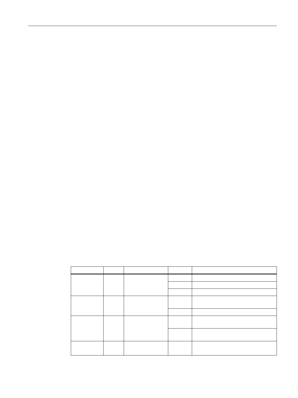
Signal
Sensor
Description
Value
Meaning
State
S1
Clamping state
3
Released
7 or 8
Clamped with tool
10
Clamped without tool
Piston free
S4
Plunger sensing
Yes
Release plunger not in contact with the
shaft.
No
Release plunger in contact with the shaft.
Shaft in the
S5
Position sensing
Yes
E.g. shaft is at a defined rotary angular
change posi-
position.
tion
No
E.g. shaft is not at a defined rotary angu-
lar position.
Speed set-
Specification of the
Speed specification by the user.
point
speed
SINUMERIK Operate
Commissioning Manual, 12/2019, 6FC5397-1DP40-6BA3
161
Spindle functions
10.3 Spindle diagnostics
Signal
Sensor
Description
Value
Meaning
State
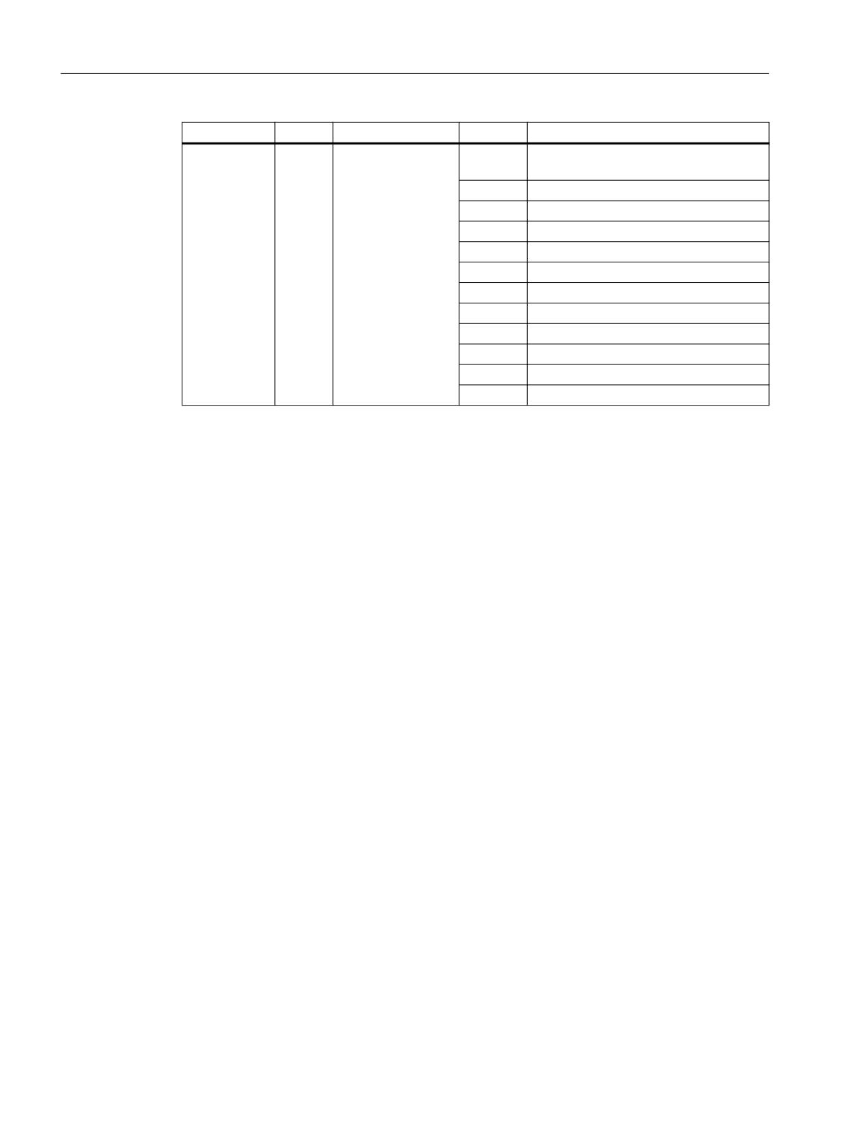
Clamping states
0
Sensor S1 not available or state values
inactive.
1
The state initialization is in progress.
2
Released with signal (error state)
3
Released
4
Clamping with tool
5
Releasing with tool
6
Releasing without tool
7
Clamped with tool and S4 = 0 (No).
8
Clamped with tool and S4 = 1 (Yes).
9
Clamping without tool
10
Clamped without tool
11
Clamped with signal (error state)
State bar diagram
The clamping state is displayed by a state bar. The ranges shown in green indicate the state
ranges for "Clamped with or without tool" and "Tool released". The arrow marking indicates the
current analog sensor voltage of sensor S1.
For information on the associated interface signals (NC → PLC), refer to the following
documentation:
References
NC Variable and Interface Signals List Manual, Section "Interface signals - Overview" > "Axis/
spindle-specific signals".
Procedure
1. The "S1 Spindle Diagnostics" window is open.
The "S1 Clamping System" window is open without the "S-Monitor" software option.
2. Press the "Clamping system" softkey.
The "S1 Clamping System" window opens and displays the acquired data.
3. Press the "Statistics" softkey to read out the clamping times and perform a diagnosis of the
clamping system.
The "S1 Clamping System Statistics" window opens and displays the acquired data.
- OR -
Press the "Back" softkey to return to the data overview.
SINUMERIK Operate
162
Commissioning Manual, 12/2019, 6FC5397-1DP40-6BA3

Spindle functions
10.3 Spindle diagnostics
10.3.8
Clamping system: Speed limits
For safety reasons and to protect the spindle, only maximum speeds are permitted for certain
clamping states. The drive limits the spindle speed in the respective clamping state to the
entered speed.
Clamping state
Meaning
Released
The tool clamping system is in contact with the release plunger.
Please note: The release plunger presses with the release force
on the clamping system.
Clamping
The tool clamping system is in the transition state from "Re-
leased" to "Clamped with tool".
Releasing from state
The tool clamping system is in the transition state from "Clamped
with tool" to "Released".
"Clamped with tool"
Releasing from state
The tool clamping system is in the transition state from "Clamped
without tool" to "Released".
"Clamped without tool"
Clamped with tool
The tool clamping system is in the "Clamped with tool" state.
Clamping without tool
The tool clamping system is in the transition state from "Clamped
with tool" to "Clamped without tool".
Clamped without tool
The tool clamping system is in the "Clamped without tool" state.
You can adapt the preset speed limits to your requirements by pressing the "Change" softkey.
NOTICE
Damage to the spindle through too high a speed
Changes to the preset speed limits can result in changes of the operating states and to
damage on the spindle.
Procedure
1. The "S1 Spindle Diagnostics" window is open.
The "S1 Clamping System" window is open without the "S-Monitor" software option.
2. Press the "Clamping system" softkey.
The "S1 Clamping System" window opens and displays the acquired data.
3. Press the "Speed limitation" softkey to change the limit values for the speeds of the
clamping states.
The "S1 Speed Limitations" window opens.
4. Press the "Change" softkey to enter the desired speed limits depending on the clamping
state.
Confirm with "OK".
SINUMERIK Operate
Commissioning Manual, 12/2019, 6FC5397-1DP40-6BA3
163

Spindle functions
10.3 Spindle diagnostics
10.3.9
Clamping system: Diagnostic statistics
This window displays the statistics for clamping operations and speed violations.
Statistical data
Meaning
Number of correct clamping cycles
Accumulated number of correct clamping cycles with or without
tool.
Correct clamping cycle means: "Released" clamping state [3] →
"Clamped" clamping state [7, 8 or 10] → "Released" clamping
state [3]. A clamping cycle is considered to be correct when a
clamping and subsequent release operation are performed via
the appropriate clamping states (without "State return"). Starting
from one clamping state, the next clamping state that can be
reached must not be the previous state. There is no dependency
on time.
Clamping time (without tool)
The time within a clamping operation between the clamping
states "Tool released" and "Clamped without tool".
● Within tolerance
Accumulated number of clamping operations without tool that
were within the specified time.
● Outside tolerance
Accumulated number of clamping operations without tool that
were outside the specified time.
● Specification
Factory specification of the time for the clamping operation with-
out tool.
● Current
Measured time for the last performed clamping operation with-
out tool.
Clamped (without tool)
Diagnostics during the "Clamped without tool" clamping state.
● Speed violations
Accumulated number of events during which the spindle speed
was greater than the set limit as delivered.
● Speed threshold
Limit for the spindle speed in the "Clamped without tool" clamp-
ing state (as-delivered value).
Changing this speed limit via the diagnostics overview "S1
clamping system" → "Speed limits" → "Change" has no effect on
the value specified here.
Faulty clamping/releasing opera-
Accumulated number of clamping operations that have not run
tions (total)
through the clamping states "Released" clamping state [3] →
"Clamped" clamping state [7, 8 or 10] → "Released" clamping
state [3] without interruption.
A clamping cycle is considered to be faulty when, starting from
one state, the next state that is reached is the previous state
again ("State return").
SINUMERIK Operate
164
Commissioning Manual, 12/2019, 6FC5397-1DP40-6BA3

Spindle functions
10.3 Spindle diagnostics
10.3.10
Clamping system: Clamping time statistics
This window displays the statistics for the determined clamping times.
Statistical data
Meaning
Last determined clamping time
Measured time for the last performed clamping operation.
Definition of a clamping operation: "Released" clamping state [3]
→ "Clamped with tool" clamping state [7 or 8]. Clamping state 3
= Released; clamping state 7 = Clamped with tool and S4 = 0
(No); clamping state 8 = Clamped with tool and S4 = 1 (Yes)
Reference clamping time (with tool)
During the spindle start-up phase, the first 100 clamping opera-
tions are measured by the SMI24 and the minimum value, max-
imum value and the mean value determined.
● Minimum
The shortest clamping time determined from the first maximum
100 clamping operations.
● Maximum
The longest clamping time determined from the first maximum
100 clamping operations.
● Mean
The mean clamping time determined from the first maximum 100
clamping operations.
Mean clamping time (without tool)
After the first 100 clamping times determined for the reference
time, the mean values for the other measured clamping times
are calculated.
●
24 h
Mean clamping time of the clamping cycles determined in the
last 24 hours.
●
10 days
Mean clamping time of the clamping cycles determined in the
last 10 days.
●
100 days
Mean clamping time of the clamping cycles determined in the
last 100 days.
If a Power On of the SMI24 is performed during the start-up phase, the previously determined
values are discarded. The counter for the first 100 clamping operations is set to zero and the
reference times up to the 100th clamping operation can be determined again. After the start-up
phase (first 100 clamping operations), the values of the reference clamping time are "frozen".
Even after a Power On of the SMI24, the values remain stored and can no longer be changed.
10.3.11
Fetching the logistics data
Requirement
The spindle characteristics can only be read out with the "Service" access level.
Spindle characteristics
The following spindle manufacturer characteristics can be read out via DRIVE-CLiQ:
● Manufacturer's identifier
● Drawing number
● Serial number
SINUMERIK Operate
Commissioning Manual, 12/2019, 6FC5397-1DP40-6BA3
165
Spindle functions
10.3 Spindle diagnostics
● Date of manufacture
● Service date and service information (1...4):
The service information corresponds to the reference number for the service report from the
WEISS Spindeltechnologie GmbH company.
SINUMERIK Operate
166
Commissioning Manual, 12/2019, 6FC5397-1DP40-6BA3
Drive system
11
11.1
Commissioning of drives
Procedure
Once commissioning of the PLC has been completed, you can carry out commissioning of the
SINAMICS drives via the user interface of SINUMERIK Operate.
1.
Select the "Start-up" operating area.
2.
Press the "Drive system" softkey.
The "Drive system overview" window opens.
A message is output whether the drive system has already been com-
missioned or not.
Additional information
The procedure for commissioning SINAMICS drives is described in the
CNC Commissioning Manual: NCK, PLC, drive.
SINUMERIK Operate
Commissioning Manual, 12/2019, 6FC5397-1DP40-6BA3
167
Drive system
11.1 Commissioning of drives
SINUMERIK Operate
168
Commissioning Manual, 12/2019, 6FC5397-1DP40-6BA3
Configuring alarms
12
12.1
Creating alarm and message texts via the user interface
From the user interface, you can create and edit your alarm and message texts from the part
program. In turn, the alarm and message texts are saved corresponding to their number in
various text files.
Storage
The text files are created in the directory:
/oem/sinumerik/hmi/lng
Procedure
1.
Select the "Start-up" operating area.
2.
Press the "HMI" softkey.
3.
Press the "Alarm texts" softkey.
The "Select File" window opens and offers the user-specific text files.
4.
Select the desired file and press the "OK" softkey.
5.
Enter the desired alarm number in the "Number" column.
Enter the desired alarm text in the "Alarm text" column.
Select the desired font color in the "Color" column.
In the column "PopUp" with "yes" or "no", select whether the alarm text
should be displayed in a window that requires acknowledgment - or
not.
- AND / OR -
Press the "Insert line" softkey.
A new line is inserted above your cursor.
- OR
Press the "Delete line" softkey to delete the selected line.
6.
Press the "Search" softkey.
The "Search" window opens.
Enter the desired alarm text or the alarm number in the "Text" field.
SINUMERIK Operate
Commissioning Manual, 12/2019, 6FC5397-1DP40-6BA3
169
Configuring alarms
12.1 Creating alarm and message texts via the user interface
Activate the "Case sensitive" checkbox if a distinction must be made
between upper- and lower-case letters when entering text.
- OR
Press the "Search and replace" softkey.
The "Search and Replace" window opens.
Enter the search term in the "Text" field. Enter the replacing term in the
"Replace with" field.
7.
Position the cursor in the "Direction" field. Using the <SELECT> key,
select the search direction (forwards, backwards).
8.
Press the "OK" softkey to start search or search and replace.
Press the "Cancel" softkey if you wish to interrupt the action.
9.
If you have entered the alarms with the help texts, press the "OK"
softkey.
You will receive the message "The alarm texts have been saved and
converted."
Restart SINUMERIK Operate
You must restart SINUMERIK Operate to ensure that the "color" and "PopUp" attributes take
effect. Modified alarm texts, however, take effect immediately.
Further search options
The cursor jumps to the first entry of the selected alarm text file.
The cursor jumps to the last entry of the selected alarm text file.
Creating search directories
If you want a search to be made for alarm files in subdirectories other than the existing /lng
directory, you have the following option:
1.
Create the file "systemconfiguration.ini" in the following directory:
/oem/sinumerik/hmi/cfg
2.
Create any subdirectory under /hmi, e.g. /oem_dir.
3.
Create the following section in the configuration file "systemconfigura-
tion.ini":
[oem_dirs]
OEM_3=oem_dir
4.
Restart SINUMERIK Operate.
The subdirectory will now also be included in the search.
SINUMERIK Operate
170
Commissioning Manual, 12/2019, 6FC5397-1DP40-6BA3
Configuring alarms
12.2 Configuring alarm and message texts via alarm text files
Foreign-language alarm and message texts
If you create foreign language alarm and message texts, switch to the desired language. All text
files are automatically allocated the language code corresponding to the user interface
language that has been selected. For instance, if you create alarm texts in the English user
interface, then the text file is assigned the "eng" language code.
See also
Range of alarms (Page 188)
Creating OEM subdirectories (Page 531)
12.2
Configuring alarm and message texts via alarm text files
You have the option of creating customized alarm and message texts using alarm text files and
adapting these.
The alarm texts are set up in standard format (".ts" format) by SINUMERIK Operate. The ".ts"
format is XML-based.
You can create and edit these files not only with SINUMERIK Operate, but also externally on
a PC.
Note
If you wish to edit alarm text files on a PC, use an editor supporting UTF-8 coding.
Note
Chinese alarm texts should only be implemented with character set GB2312.
Chinese logograms are not supported in Korean.
Creating and editing alarm texts
● Creating your own alarm texts
● Creating texts for indexed alarm parameters
● Creating part program message texts
● Changing alarm attributes
● Replacing standard alarm texts
● Converting alarm texts
SINUMERIK Operate
Commissioning Manual, 12/2019, 6FC5397-1DP40-6BA3
171
Configuring alarms
12.2 Configuring alarm and message texts via alarm text files
12.2.1
Creating in-house alarm texts
Creating an alarm text file
1. You can copy a sample file "oem_alarms_eng.ts" from the following directory: /siemens/
sinumerik/hmi/template/lng
2. Save or create the file in the /oem/sinumerik/hmi/lng or
/user/sinumerik/hmi/lng directory. Create a separate file for each country language that is
supported.
3. Assign a unique name to the file, e.g. "my_alarms_eng.ts". You can freely select the file
names with the exception of the language code and the extension.
The file name always ends with the language code of the particular language and always
has the ".ts" extension. For example "my_alarms_deu.ts" for German or
"my_alarms_eng.ts" for English.
Creating alarm texts
1. Open the "my_alarms_eng.ts" file.
2. For each alarm text, you must insert your own area in the file that is marked using the
<message> tag.
3. The <name> tag contains the context names. Normally, you should not change the specified
name "slaeconv".
4. The <source> tag contains the alarm number and the name of the alarm source (source
URL). In the example "700000" is the alarm number and "/PLC/PMC" is the name of the
alarm source. The possible alarm sources can be found in the tables in Section Range of
alarms (Page 188).
5. The <translation> tag contains the alarm text.
Example:
<!DOCTYPE TS>
<TS>
<context>
<name>slaeconv</name>
<message>
<source>700000/PLC/PMC</source>
<translation>First OEM alarm text</translation>
</message>
<message>
<source>700001/PLC/PMC</source>
<translation>Second OEM alarm text</translation>
</message>
</context>
</TS>
SINUMERIK Operate
172
Commissioning Manual, 12/2019, 6FC5397-1DP40-6BA3
Configuring alarms
12.2 Configuring alarm and message texts via alarm text files
Registering the alarm text file
You still have to register your alarm text file so that the system knows your alarm texts during
the program runtime:
1. You can copy a sample configuration file "oem_slaesvcadapconf.xml" from the following
directory: /siemens/sinumerik/hmi/template/cfg
2. Save the file in the directory /oem/sinumerik/hmi/cfg or
/user/sinumerik/hmi/cfg
3. Assign the name "slaesvcadapconf.xml" to the file.
4. Open the file and in the <BaseNames> tag, enter the file name of the alarm text file without
language code and file extension, e.g. "my_alarms", as "value".
The registration of your alarm text file starts, for example, with the name
"OEM_BaseName_01".
Note
The names of the <BaseNames> tag can be freely selected. They must be unique in the
system and must not clash with names used by Siemens.
The "Siemens_BaseName_01" name is reserved for Siemens.
Several alarm text files can also be registered. To do this, use names such as
"OEM_BaseName_02", "OEM_BaseName_03", etc.
Example:
<?xml version="1.0" encoding="UTF-8" standalone="yes"?>
<!-- Configuration of the Solutionline Alarm & Event Service Adapter
-->
<CONFIGURATION>
<AlarmTexts>
<BaseNames>
<OEM_BaseName_01 type="QString" value="my_alarms"/>
</BaseNames>
</AlarmTexts>
</CONFIGURATION>
Restart SINUMERIK Operate
The files must still be converted into a binary format so that the alarm texts can be displayed
during the program runtime. This data is only converted during power up.
To do this, restart SINUMERIK Operate. In the same directory where the .ts files are located,
files with the same name are created with the ".qm" file extension.
The result of the conversion is written to the "alarmtext_conversion.log" or
"oem_text_conversion.log" file. Errors that occur during the conversion, such as syntax errors
in a parameter file, are also written to the file.
SINUMERIK Operate
Commissioning Manual, 12/2019, 6FC5397-1DP40-6BA3
173
Configuring alarms
12.2 Configuring alarm and message texts via alarm text files
This file is located in the "/user/sinumerik/hmi/log" directory.
Note
The conversion is only made if the .ts file is newer than the associated .qm file.
12.2.2
Creating texts for indexed alarm parameters
If a string, the so-called "Index identifier", is specified in the alarm text in pointed brackets after
a space holder (e.g. "%1<OEM>"), the parameter itself is not inserted in the alarm text, but
a text from another alarm text file, a so-called index text file. In this case, the alarm parameter
value serves as index in order to select the text in the index file. The index text can, in turn,
include parameters, also index parameters.
Note
Explanation for the "Index identifier" string
● "<" ≙ opening pointed bracket "<"
● ">" ≙ closing pointed bracket ">"
Creating an index text file
1. You can copy a sample index text file "oem_indexparams_eng.ts" from the following
directory: /siemens/sinumerik/hmi/template/lng
2. Save or create the file in the /oem/sinumerik/hmi/lng or
/user/sinumerik/hmi/lng directory. Create a separate file for each country language that is
supported.
3. Assign a unique name to the file, e.g. "my_indextexts_eng.ts". You can freely select the file
names with the exception of the language code and the extension.
The file name always ends with the language code of the particular language and always
has the ".ts" extension. For instance, "my_indextexts_deu.ts" for German or
"my_indextexts_eng.ts" for English.
Creating index texts
1. Open the "my_indextexts_eng.ts" file.
2. In the <name> tag, enter a name that you have selected, e.g. "my_context".
3. For each index text, a separate area must be inserted between the <message> and </
message> tags.
4. The <source> tag contains the alarm parameter value, e.g. the values "1" and "2".
5. The <translation> tag includes the index text that is displayed if the alarm parameter
involved has the value specified between <source> and </source>.
SINUMERIK Operate
174
Commissioning Manual, 12/2019, 6FC5397-1DP40-6BA3
Configuring alarms
12.2 Configuring alarm and message texts via alarm text files
Example
<!DOCTYPE TS>
<TS>
<context>
<name>my_context</name>
<message>
<source>1</source>
<translation>First OEM parameter text</translation
</message>
<message>
<source>2</source>
<translation>Second OEM parameter text</translation
</message>
</context>
</TS>
Registering an index text file
You still have to register your index text file so that the system knows your index texts during
the program runtime. The registration is made in the "slaesvcadapconf.xml" file.
1. Open the file "slaesvcadapconf.xml" already created for the alarm texts /oem/sinumerik/hmi/
cfg or /user/sinumerik/hmi/cfg directory.
2. Remove the lines "<!-- Start of comment" and "End of comment -->".
3. Enter the so-called identifier, e.g. <Identifier type="QString" value="OEM"/>. The index
identifier is always specified in pointed brackets next to the parameter specification in the
alarm text, e.g. "%1<OEM>".
4. Enter the BaseName of the index text file, e.g.
<BaseName type="QString" value="my_indextexts"/>.
5. Enter the context name that you selected, e.g.
<ContextName type="QString" value="my_context"/>.
6. You can also use several different indices. Then, in this case, a dedicated section must be
created for every index between the <IndexTexts> and </IndexTexts> tags. The tags for
these sections are called, e.g.
<OEM_IndexText_01>, <OEM_IndexText_02>, <OEM_IndexText_03>, etc.
The tags <IndexText_01> to <IndexText_99> are reserved for Siemens.
Example
<?xml version="1.0" encoding="UTF-8" standalone="yes"?>
<!- Configuration of the Solutionline Alarm & Event Service Adapter
->
<CONFIGURATION>
SINUMERIK Operate
Commissioning Manual, 12/2019, 6FC5397-1DP40-6BA3
175
Configuring alarms
12.2 Configuring alarm and message texts via alarm text files
<!-- The following narrated part of the configuration is used
only when 'Indexparameters' (e.g. '%1<OEM>') are used
within OEM alarm texts. In this case the value of the parameter
is used as an index into an additional text list to reference
another text which is placed into the alarm text instead of the
original parameter value. -->
<IndexTexts>
<OEM_IndexText_01>
<Identifier type="QString" value="OEM"/>
<BaseName type="QString" value="my_indextexts"/>
<ContextName type="QString" value="my_context"/>
<MetaTextID type="QString" value="%ParamValue%"/>
</OEM_IndexText_01>
</IndexTexts>
</CONFIGURATION>
Restart SINUMERIK Operate
The files must still be converted into a binary format so that the alarm texts can be displayed
during the program runtime. This data is only converted during power up.
To do this, restart SINUMERIK Operate. In the same directory where the .ts files are located,
files with the same name are created with the ".qm" file extension.
The result of the conversion is written to the "alarmtext_conversion.log" or
"oem_text_conversion.log" file. Errors that occur during the conversion, such as syntax errors
in a parameter file, are also written to the file.
This file is saved in the /user/sinumerik/hmi/log directory.
Note
The conversion is only made if the .ts file is newer than the associated .qm file.
12.2.3
Creating part program message texts
Message texts from the part program
In order to output message texts from the part program, use the MSG instruction in the part
program. The message texts are referenced via the number after the "$ character, e.g.
MSG("$4711"). You can configure channel-specific message texts for each NC channel.
SINUMERIK Operate
176
Commissioning Manual, 12/2019, 6FC5397-1DP40-6BA3
Configuring alarms
12.2 Configuring alarm and message texts via alarm text files
Creating message texts
Procedure:
1. You can copy a sample message text file "oem_pp_messages_eng.ts" from the following
directory: /siemens/sinumerik/hmi/template/lng
2. Save or create the file in the /oem/sinumerik/hmi/lng or
/user/sinumerik/hmi/lng directory. Create a separate file for each country language that is
supported.
3. Assign a unique name to the file, e.g. "my_msgs_eng.ts". You can freely select the file
names with the exception of the language code and the extension.
The file name always ends with the language code of the particular language and always
has the ".ts" extension. For instance, "my_msgs_deu.ts" for German or "my_msgs_eng.ts"
for English.
4. Open the "oem_msgs_eng.ts" file and in the <name> tag enter the "partprogmsg01"
character string. This is the default for the part program message texts from all channels.
5. For each message text, a separate area must be inserted between the <message> and </
message> tags.
6. The <source> tag contains the number from the MSG command in the part program.
7. The <translation> tag contains the message text.
Example
<!DOCTYPE TS>
<TS>
<context>
<name>partprogmsg01</name>
<message>
<source>4711</source>
<translation>part program message No. 4711</translation
</message>
</context>
</TS>
Registering the message text file
You still have to declare your message text file so that the system knows your message texts
during the program runtime.
1. You can copy a sample configuration file "oem_slaesvcadapconf.xml" from the following
directory: /siemens/sinumerik/hmi/template/cfg
2. Save or create the file in the /oem/sinumerik/hmi/cfg or
/user/sinumerik/hmi/cfg directory.
SINUMERIK Operate
Commissioning Manual, 12/2019, 6FC5397-1DP40-6BA3
177
Configuring alarms
12.2 Configuring alarm and message texts via alarm text files
3. Change the name to "slaesvcadapconf.xml".
4. Open the file and in the <BaseNames> tag enter the file name of the message text file
without language code and file extension, e.g. "my_msgs", as "value". The registration of
your message text file starts, for example, with the name "OEM_BaseName_01".
Note
The names of the <BaseNames> tag can be freely selected. They must be unique in the
system and must not clash with names used by Siemens.
The "Siemens_BaseName_01" name is reserved for Siemens.
Several message text files can also be registered. To do this, use names such as
"OEM_BaseName_02", "OEM_BaseName_03", etc.
Example
<?xml version="1.0" encoding="UTF-8" standalone="yes"?>
<!-- Configuration of the Solutionline Alarm & Event Service Adapter
-->
<CONFIGURATION>
<AlarmTexts>
<BaseNames>
<OEM_BaseName_01 type="QString" value="my_msgs"/>
</BaseNames>
</AlarmTexts>
</CONFIGURATION>
Message texts for several channels
It is possible to assign different message texts the same message number, e.g. the number
4711 in different NC channels. This means, different message texts are output depending on
the channel in which the part program is executed.
1. Open the "oem_msgs_eng.ts" file in the editor.
2. Change the text between the two <name> and </name> tags from "partprogmsg01" into
"partprogmsgXY", whereby "XY" should be replaced by the particular channel number, e.g.
"partprogmsg02" for channel 2.
3. Now open the "slaesvcconf.xml" configuration file.
4. Enter the respective NC channel in the <Connections> tag. Only use the XML tags from the
following table to specify the NC channel.
NC chan-
XML tag
ContextName
nel
1
PartprogramMessageChannel_01
partprogmsg01
2
PartprogramMessageChannel_02
partprogmsg02
SINUMERIK Operate
178
Commissioning Manual, 12/2019, 6FC5397-1DP40-6BA3

Configuring alarms
12.2 Configuring alarm and message texts via alarm text files
NC chan-
XML tag
ContextName
nel
3
PartprogramMessageChannel_03
partprogmsg03
4
PartprogramMessageChannel_04
partprogmsg04
5
PartprogramMessageChannel_05
partprogmsg05
6
PartprogramMessageChannel_06
partprogmsg06
7
PartprogramMessageChannel_07
partprogmsg07
8
PartprogramMessageChannel_08
partprogmsg08
9
PartprogramMessageChannel_09
partprogmsg09
10
PartprogramMessageChannel_10
Partprogmsg10
Example
<?xml version="1.0" encoding="UTF-8" standalone="yes"?>
<!-- Configuration of the Solutionline Alarm & Event Service Adapter
-->
<CONFIGURATION>
<Connections>
<PartprogramMessageChannel_02>
<ContextName type="QString" value="partprogmsg02"/>
</PartprogramMessageChannel_02>
</Connections>
</CONFIGURATION>
Restart SINUMERIK Operate
The files must still be converted into a binary format so that the alarm texts can be displayed
during the program runtime. This data is only converted during power up.
To do this, restart SINUMERIK Operate. In the same directory where the .ts files are located,
files with the same name are created with the ".qm" file extension.
The result of the conversion is written to the "alarmtext_conversion.log" or
"oem_text_conversion.log" file. Errors that occur during the conversion, such as syntax errors
in a parameter file, are also written to the file.
This file is saved in the /user/sinumerik/hmi/log directory.
Note
The conversion is only made if the .ts file is newer than the associated .qm file.
SINUMERIK Operate
Commissioning Manual, 12/2019, 6FC5397-1DP40-6BA3
179
Configuring alarms
12.2 Configuring alarm and message texts via alarm text files
12.2.4
Changing alarm attributes
Color types of the alarms
You can individually change the colors of the alarms and messages displayed in the message
line.
You can change the following for each alarm number and alarm source:
● Font color of the alarm/message text
● Background color of the alarm/message text
● Font color of the alarm number
● Background color of the alarm number
Create alarm attribute file
Procedure:
1. You can copy a sample alarm attribute file "oem_slaedatabase.xml" from the
directory: /siemens/sinumerik/hmi/template/cfg/
2. Save the file in the directory /oem/sinumerik/hmi/cfg/ or
/user/sinumerik/hmi/cfg/
3. Assign a unique name to the file, e.g. " muster_slaedatabase.xml ".
The file name can be freely selected; however, it must only contain lower-case letters.
Defining alarm colors
Procedure:
1. Open the file "muster_slaedatabase.xml" in the editor.
2. First, enter which alarm colors you generally wish to change.
To do this, create a separate section <Attribute> for each alarm color that you wish to
change in the <Attributes> area.
3. Enter the attribute name of the alarm color to be changed in the <Attribute AttrName=…>
tag. You can change the following colors:
- Font color of the alarm/message text = TEXTCOLOR
- Background color of the alarm/message text = TEXTBACKGROUNDCOLOR
- Font color of the alarm number = NUMBERCOLOR
- Background color of the alarm number = NUMBERBACKGROUNDCOLOR
SINUMERIK Operate
180
Commissioning Manual, 12/2019, 6FC5397-1DP40-6BA3
Configuring alarms
12.2 Configuring alarm and message texts via alarm text files
4. Alarm sources are defined in the <Sources> area for whose alarms the alarm colors are to
be changed, e.g. the alarm sources "/HMI" and "/PLC/PMC".
Note
If you insert further alarm sources, make sure that the alarm number is always assigned to
the correct alarm source.
The possible values for source ID and URL can be found in the table in Section Range of
alarms (Page 188).
5. In the <Alarms> tag, create a separate sub-area for each alarm or for an alarm number
range.
6. Enter the alarm number in the <Alarm AlarmID= "..." > tag, or enter the alarm number range
in the <Range FromAlarmID="..." ToAlarmID= "..."> tag.
7. Enter the required color values in the following tags:
<TEXTCOLOR>
<TEXTBACKGROUNDCOLOR>
<NUMBERCOLOR>
<NUMBERBACKCOLOR>
The attributes of the color values are defined by specifying an RGB value:
- An RGB value always starts with the "#" character.
- The individual color values R, G and B are represented by double-digit hexadecimal
numbers. Syntax: "#RRGGBB", e.g. "#FF9A00".
Example
Note the order in the XML configuration file for the assignment of the colors to alarm number
ranges:
<?xml version="1.0" encoding="UTF-8"?>
<!DOCTYPE SlAeAlarmAttributes>
<SlAeAlarmAttributes Version="01.00.00.00">
<Types>
<Type TypeName="Condition" TypeID="32">
<Category Version="1.0" CatID="1">
<CatDescr>Alarms of the SINUMERIK 840D sl.</CatDescr>
<Attributes>
<Attribute AttrName="TEXTCOLOR" AttrID="5003"
AttrDataType="10">
<AttrDescr>
Text color of an alarm used when displayed within the
header panel.
</AttrDescr>
</Attribute>
<Attribute AttrName="TEXTBACKGROUNDCOLOR" AttrID="5004"
AttrDataType="10">
SINUMERIK Operate
Commissioning Manual, 12/2019, 6FC5397-1DP40-6BA3
181
Configuring alarms
12.2 Configuring alarm and message texts via alarm text files
<AttrDescr>
Background color of an alarm used when displayed within
the header panel.
</AttrDescr>
</Attribute>
<Attribute AttrName="NUMBERCOLOR" AttrID="5005"
AttrDataType="10">
<AttrDescr>
Text color of an alarm used when displayed within the
header panel.
</AttrDescr>
</Attribute>
<Attribute AttrName=" NUMBERBACKGROUNDCOLOR " AttrID="5006"
AttrDataType="10">
<AttrDescr> Background color of an alarm used when
displayed within the header panel.
</AttrDescr>
</Attribute>
</Attributes>
</Category>
</Type>
</Types>
<Sources>
<Source> CatLink="1" SourceID="10000" SourceURL="/HMI">
<Alarms>
<Alarm AlarmID="130000">
<TEXTCOLOR>#000000</TEXTCOLOR>
<TEXTBACKGROUNDCOLOR>#FFFFFF</TEXTBACKGROUNDCOLOR>
<NUMBERCOLOR>#FFFFFF</NUMBERCOLOR>
<NUMBERBACKGROUNDCOLOR>#000000</NUMBERBACKGROUNDCOLOR
</Alarm>
</Alarms>
</Source>
<Source> CatLink="1" SourceID="51" SourceURL="/PLC/PMC">
<Alarms>
<Range FromAlarmID="700100" ToAlarmID="700199">
<TEXTCOLOR>#000000</TEXTCOLOR>
<NUMBERCOLOR>#00FF00</NUMBERCOLOR>
</Range>
<Alarm AlarmID="700000">
<TEXTCOLOR>#000000</TEXTCOLOR>
<TEXTBACKGROUNDCOLOR>#FFFFFF</TEXTBACKGROUNDCOLOR>
<NUMBERCOLOR>#FFFFFF</NUMBERCOLOR>
SINUMERIK Operate
182
Commissioning Manual, 12/2019, 6FC5397-1DP40-6BA3
Configuring alarms
12.2 Configuring alarm and message texts via alarm text files
<NUMBERBACKGROUNDCOLOR>#000000</NUMBERBACKGROUNDCOLOR
</Alarm>
</Alarms>
</Source>
</Sources>
</SlAeAlarmAttributes>
Registering the alarm attribute file
The alarm attribute file with the color definitions must be registered in order that the alarm colors
can be assigned to the alarms during the program runtime:
1. You can copy a sample configuration file "oem_slaesvcconf.xml" from the following
directory: /siemens/sinumerik/hmi/template/cfg
2. Save or create the file in the /oem/sinumerik/hmi/cfg or
/user/sinumerik/hmi/cfg directory.
3. Name the file "slaesvcconf.xml".
4. Open the file and in the <DataBases> tag enter, for example, the file name of the alarm
attribute file without language code and file extension, e.g. "muster_slaedatabase", as
"value". The registration of your alarm attribute file starts, for example, with the name
"OEM_DataBase_01".
Note
The names of the <DataBases> tag can be freely selected. They must be unique in the
system and must not clash with names used by Siemens.
The "Siemens_DataBase_01" name is reserved for Siemens.
If you register additional alarm attribute files, i.e. you wish to include them in the
configuration file, use names such as "OEM_DataBase_02", "OEM_DataBase_03", etc.
Restart SINUMERIK Operate
The files still have to be converted into a binary format in order that the alarm colors become
effective during the program runtime. This data is only converted during power up.
To do this, restart SINUMERIK Operate. A file with the same name is created with the ".hmi" file
extension, e.g. "sample_slaedatabase.hmi" in the same directory in which the alarm attribute
file is also located.
The result of the conversion is written to the file "oem_ae_database_conversion.log". This file
is located in the "/user/sinumerik/hmi/log" directory.
Note
The conversion is only carried out if the XML file is newer than the associated hmi file.
SINUMERIK Operate
Commissioning Manual, 12/2019, 6FC5397-1DP40-6BA3
183
Configuring alarms
12.2 Configuring alarm and message texts via alarm text files
12.2.5
Replacing standard alarm texts
You can replace alarm texts of the standard SINUMERIK Operate with own alarm texts.
Creating an alarm text file
1. You can copy a sample alarm text file "oem_alarms_eng.ts" from the following
directory: /siemens/sinumerik/hmi/template/lng
2. Save or create the file in the /oem/sinumerik/hmi/lng or
/user/sinumerik/hmi/lng directory. Create a separate file for each country language that is
supported.
3. Assign the file a user-specific name, e.g. "my_nck_alarms_eng.ts". You can freely select the
file names with the exception of the language code and the extension.
The file name always ends with the language code of the particular language and always
has the ".ts" extension. For example "my_nck_alarms_deu.ts" for German or
"my_nck_alarms_eng.ts" for English.
Creating alarm texts
1. Open the "my_nck_alarms_eng.ts" file.
2. A separate area must be inserted for each alarm text, marked by the <message> tag.
3. The <name> tag contains the context names. Change the name and ensure that the name
is unique in the system, e.g. "myNckAlarms".
Note
The name for the <name> tag can always be freely selected. However, the name must not
clash with the "slaeconv" name used by Siemens.
4. The <source> tag contains the alarm number of the standard alarm, e.g. 10000.
5. The <translation> tag contains the actual alarm text, e.g. "OEM alarm text example for NCK
alarm 10.000".
Example
<!DOCTYPE TS>
<TS>
<context>
<name>myNckAlarms</name>
<message>
<source>10000/NCK</source>
<translation> OEM alarm text example for NCK alarm 10.000</
translation>
</message>
</context>
<TS>
SINUMERIK Operate
184
Commissioning Manual, 12/2019, 6FC5397-1DP40-6BA3
Configuring alarms
12.2 Configuring alarm and message texts via alarm text files
Registering the alarm text file
You still have to register your alarm text file so that the system knows your alarm texts during
the program runtime:
1. You can copy a sample configuration file "oem_slaesvcadapconf.xml" from the following
directory: /siemens/sinumerik/hmi/template/cfg
2. Save or create the file in the /oem/sinumerik/hmi/cfg or
/user/sinumerik/hmi/cfg directory.
3. Assign the name "slaesvcadapconf.xml" to the file.
4. Open the file and in the <BaseNames> tag enter the file name of your alarm text file without
language code and file extension, e.g. "my_nck_alarms", as "value". The registration of your
alarm text file starts, for example, with the name "Siemens_BaseName_01".
Note
The names of the <BaseNames> tag can be freely selected. They must be unique in the
system and must not clash with names used by Siemens.
The "Siemens_BaseName_01" name is reserved for Siemens.
Several alarm text files can also be registered. To do this, use names such as
"OEM_BaseName_02", "OEM_BaseName_03", etc.
Example:
<?xml version="1.0" encoding="UTF-8" standalone="yes"?>
<!-- Configuration of the Solutionline Alarm & Event Service Adapter
-->
<CONFIGURATION>
<AlarmTexts>
<BaseNames>
<OEM_BaseName_01 type="QString" value="my_nck_alarms"/>
</BaseNames>
</AlarmTexts>
</CONFIGURATION>
Replacing standard alarm texts
You still have to define which standard alarm texts should be replaced by your alarm texts so
that during the program runtime, the original alarm text is replaced by your alarm text.
1. Create a new alarm attribute file (see Changing alarm attributes (Page 180)) in the /oem/
sinumerik/hmi/cfg or /user/sinumerik/hmi/cfg directory. The file name can be freely
selected, e.g. "my_nck_alarms_db.xml".
2. Open the file.
3. The file always comprises the two areas <Types> and <Sources>.
4. The <sources> tag includes the reference, assigned to an alarm source, e.g. "\NCK", to the
associated alarm text.
SINUMERIK Operate
Commissioning Manual, 12/2019, 6FC5397-1DP40-6BA3
185
Configuring alarms
12.2 Configuring alarm and message texts via alarm text files
5. Link the contents of the <context> <name> tags with the contents of the <message>
<source> tags from your alarm text file.
- <context> <name> = the context name that you assigned
- <message> <source> = the number of the alarm whose text is to be replaced.
E.g. enter the following link in the alarm attribute file: <MSGTEXT>myNckAlarms Ι
10000</MSGTEXT>
Make sure that the context name and the alarm number are separated by the pipe
character "Ι".
6. If you include an additional NCK alarm, copy the range from <Alarms> to </Alarms> and
adapt the alarm number.
7. If you include an additional alarm from another number range (e.g. PLC alarm), copy the
range <Sources> to </Sources> and then adapt the SourceID and SourceURL as well as
the alarm number.
You can take the corresponding SourceID and SourceURL from the table in Section Range
of alarms (Page 188).
Note
A dedicated link must be created for each standard alarm for which the text is to be replaced.
Example
<?xml version="1.0" encoding="UTF-8"?>
<!DOCTYPE SlAeAlarmAttributes>
<SlAeAlarmAttributes Version="01.00.00.00">
<Types>
<Type TypeName="Condition" TypeID="32">
<Category Version="1.0" CatID="1">
<CatDescr>Alarms of the Sinumerik 810/840 D(i).</CatDescr>
<Attributes>
</Attributes>
</Category>
</Type>
</Types>
<Sources>
<Source CatLink="1" SourceID="0" SourceURL="/NCK">
<Alarms>
<Alarm AlarmID="10000">
<MSGTEXT>myNckAlarms|10000/NCK</MSGTEXT>
</Alarm>
</Alarms>
</Source>
SINUMERIK Operate
186
Commissioning Manual, 12/2019, 6FC5397-1DP40-6BA3
Configuring alarms
12.2 Configuring alarm and message texts via alarm text files
</Sources>
</SlAeAlarmAttributes>
Registering the alarm attribute file
The alarm attribute file still has to be registered in order that the standard alarm texts are
replaced during the program runtime:
1. You can copy a sample configuration file "oem_slaesvcconf.xml" from the following
directory: /siemens/sinumerik/hmi/template/cfg
2. Save or create the file in the /oem/sinumerik/hmi/cfg or
/user/sinumerik/hmi/cfg directory.
3. Change the name to "slaesvcconf.xml".
4. Open the file and in the <DataBases> tag enter the name of the alarm attribute file, e.g.
<OEM_DataBase_01 type="QString" value="my_nck_alarms_db">
Note
The names of the <DataBases> tag can be freely selected. They must be unique in the
system and must not clash with names used by Siemens.
The <Siemens_DataBase_01> tag name is reserved for Siemens.
If you register additional alarm attribute files, i.e. you wish to include them in the
configuration file, use the names <OEM_DataBase_02>, <OEM_DataBase_03>, etc.
Restart SINUMERIK Operate
The files with the alarm texts and the attribute file still have to be converted into a binary format
in order that the alarm texts can be displayed during the program runtime. This data is only
converted during power up.
To do this, restart SINUMERIK Operate. In the same directory where the .ts files or the alarm
attribute file are located, files with the same name are created with the ".qm" and .hmi file
extension.
The result of the conversion is written to the "alarmtext_conversion.log" or
"oem_text_conversion.log" file. Errors that occur during the conversion, such as syntax errors
in a parameter file, are also written to the file.
This file is located in the "/user/sinumerik/hmi/log" directory.
Note
The conversion is only made if the .ts file is newer than the associated .qm file.
SINUMERIK Operate
Commissioning Manual, 12/2019, 6FC5397-1DP40-6BA3
187
Configuring alarms
12.2 Configuring alarm and message texts via alarm text files
12.2.6
Range of alarms
Number ranges of alarms
Numerical range
Description
SourceID
SourceURL
000 000 ... 009 999
General alarms
0 (standard
/NCK
NCU)
010 000 ... 019 999
Channel alarms
//configura-
100 (1. NCU)
tion_spec. Designa-
020 000 ... 029 999
Axis/spindle alarms
tion>//NCK
030 000 ... 039 999
Functional alarms
General
9999 (99. NCU)
040 000 ... 059 999
Reserved
060 000 ... 064 999
Siemens cycle alarms
065 000 ... 069 999
Cycle alarms user
070 000 ... 079 999
Compile cycles
Manufacturer and OEM
080 000 ... 084 999
Siemens cycles mes-
sage texts
085 000 ... 089 999
User cycles message
texts
090 000 ... 099 999
Reserved
100 000 ... 129 999
System
10 000
/HMI
130 000 ... 139 999
OEM
140 000 ... 199 999
Reserved
200 000 ... 299 999
SINAMICS drive
0
/NCK
300 000 ... 399 999
Drive and I/O alarms
400 000 ... 499 999
General alarms
51
/PLC/PMC
500 000 ... 599 999
Channel alarms
600 000 ... 699 000
Axis/spindle alarms
700 000 ... 799 999
User area
800 000 ... 899 999
Sequencers/graphs
810 000 ... 810 009
System error messages
50
/PLC/DiagBuffer
150 (1st NCU)
//<configuration-spec.
Designation>/PLC/
DiagBuffer
900 001 ... 965 999
HMI PRO sl Runtime
966 000 ... 999 999
Reserved
SourceIDs 1 ... 10
The SourceIDs 1 ... 10 have the following relationship:
SourceID
SourceURL
1
/NCK/Channel#1/Partprogram
2
/NCK/Channel#2/Partprogram
3
/NCK/Channel#3/Partprogram
4
/NCK/Channel#4/Partprogram
SINUMERIK Operate
188
Commissioning Manual, 12/2019, 6FC5397-1DP40-6BA3
Configuring alarms
12.2 Configuring alarm and message texts via alarm text files
SourceID
SourceURL
5
/NCK/Channel#5/Partprogram
6
/NCK/Channel#6/Partprogram
7
/NCK/Channel#7/Partprogram
8
/NCK/Channel#8/Partprogram
9
/NCK/Channel#9/Partprogram
10
/NCK/Channel#10/Partprogram
12.2.7
Parameter specifications in alarm texts
Alarm texts can contain alarm parameters (accompanying values) that specify the cause of an
alarm in more detail. These parameters are usually numerical values that are transmitted from
an alarm source when the alarm is signaled along with the other alarm data.
How the parameters are incorporated into the alarm text is specified via place holders
(parameter specifications) in the language-specific alarm texts, e.g. "Channel %1 Axis %2 in
machine data %3 defined for several channels".
When an alarm occurs, the text is replaced by the corresponding parameters, e.g. "Channel 5
Axis A3 in machine data 4711 defined for several channels".
Standard parameter specifications
The following table shows the standard parameter specifications:
Table 12-1
Standard parameter specifications
Parameter
Description
specifier
%1
First parameter from the alarm data of the alarm source.
%2
Second parameter from the alarm data of the alarm source.
%3
Third parameter from the alarm data of the alarm source.
%4
Fourth parameter from the alarm data of the alarm source.
%5
Fifth parameter from the alarm data of the alarm source.
Only for NCK alarms:
First part (up to the separator) of the fourth parameter from the alarm data of the alarm
source.
%7
Seventh parameter from the alarm data of the alarm source
Only for NCK alarms:
Third part (between the 2nd and 3rd separator) of the fourth parameter from the alarm
data of the alarm source.
%8
Eighth parameter from the alarm data of the alarm source
Only for NCK alarms:
Fourth part (between the 3rd and 4th separator) of the fourth parameter from the alarm
data of the alarm source.
%9
Ninth parameter from the alarm data of the alarm source.
%0
Tenth parameter from the alarm data of the alarm source.
SINUMERIK Operate
Commissioning Manual, 12/2019, 6FC5397-1DP40-6BA3
189
Configuring alarms
12.3 Configuring an alarm log
Parameter
Description
specifier
%Z
As for %1, in the case of S7-HiGraph alarms the step number of the graph is shown.
%K
Specially for PLC alarms:
Second digit of the decimal alarm ID: 123456, corresponds to channel number (0 =
channel 10).
%A
Specially for PLC alarms:
Third and fourth digit of the decimal alarm ID: 123456, corresponds to the axis number.
%N
Specially for PLC alarms:
Fifth and sixth digit of the decimal alarm ID: 123456, corresponds to the signal number.
12.2.8
Opening error file
The errors that occur during the conversion are written to the "alarmtext_conversion.log" or
"oem_text_conversion.log" file.
File loc.: /user/sinumerik/hmi/log
Opening the error file
1.
Select the "Start-up" operating area.
2.
Press the "System data" softkey.
3.
Open the "System CF card" folder.
4.
Open the storage directory and select the required file.
5.
To open the error file, press the "Open" softkey.
- OR -
Press the <INPUT> key.
12.3
Configuring an alarm log
Default setting
Per default, the alarm log contains all alarms and messages - with their incoming and outgoing
time stamps - in chronological order since the last boot. The exceptions are messages from the
NC part program (msg command).
Contrary to the "Alarm List" or "Messages" window, all of the alarms or messages that are no
longer active when the log is displayed are also displayed (historical alarm events).
SINUMERIK Operate
190
Commissioning Manual, 12/2019, 6FC5397-1DP40-6BA3
Configuring alarms
12.3 Configuring an alarm log
Specifying the number of events
The alarm log is organized as a ring buffer: When the maximum size is exceeded, the oldest
entries are overwritten by the new alarm events. Each event (Incoming, Outgoing,
Acknowledgement, etc.) represents a separate entry. The maximum size of the alarm log does
not refer to the number of alarms it contains but the number of entries.
Persistent storage (permanent storage)
If required, the alarm log can be set up as a persistent log that also contains alarm events from
before the last time it was switched on. This means that the log is then either time controlled or
for each alarm event is backed-up in an internal binary format in the file system.
Depending on the hardware being used, the alarm log for the NCU is saved on the
CompactFlash card or for the PC/PCU, on the hard disk.
NOTICE
Shorter CF card service life
If the alarm log is a continuously written to the CompactFlash card, then only a limited number
of write cycles is possible. Therefore, ensure that storage is only performed when there is a
justifiable need! Undo the setting "at every event" when you no longer require the alarm log to
be saved.
The CompactFlash card has a service life of over 10 years for an average written data volume
of approx. 60 MB/day.
The alarm log is not saved in the default configuration.
Configuring an alarm log
● Via the operator software in the "Diagnostics" operating area
● Via the "slaesvcconf.xml" configuration file
12.3.1
Setting alarm logs from the user interface
Procedure
1.
Select the "Diagnostics" operating area.
2.
Press the "Alarm log" and "Settings" softkeys.
SINUMERIK Operate
Commissioning Manual, 12/2019, 6FC5397-1DP40-6BA3
191
Configuring alarms
12.3 Configuring an alarm log
3.
Enter a number in the "Number of entries" field to change the maximum
number of administered incoming and outgoing events.
The alarm log is organized as a ring buffer: When the maximum size is
exceeded, the oldest entries are overwritten by the new alarm events.
Each incoming or outgoing time stamp represents a separate event.
You can specify a value between 500 and 32000. Default value is 500.
4.
In the "Write mode file" field, under the following entry, select:
● "off", the changes are not logged (default setting)
● "for each event", each alarm event immediately initiates backup of the
alarm log (persistent save).
● "time controlled" if the alarm log is to be backed up again after a
certain time. An additional input field called "Time interval" appears in
which you can specify a time in seconds.
You receive a warning if you only save to a CompactFlash card.
Restart SINUMERIK Operate
The settings made take effect only after a restart of the operating software. To do this, restart
SINUMERIK Operate.
12.3.2
Loading alarm log via configuration file
Creating the configuration file
Adjustments are made in file "slaesvcconf.xml". Copy a sample configuration file
"oem_alarmprot_slaesvcconf.xml" from the following directory: /siemens/sinumerik/hmi/
template/cfg.
Procedure:
1. Save or create the file in the /oem/sinumerik/hmi/cfg or
/user/sinumerik/hmi/cfg directory.
2. Assign the name "slaesvcconf.xml" to the file.
3. Open the file and enter the number of events to be output in the tag <Records type .../>. The
default value is 500. The maximum number depends on the storage medium (hard disk or
CompactFlash card).
SINUMERIK Operate
192
Commissioning Manual, 12/2019, 6FC5397-1DP40-6BA3

Configuring alarms
12.3 Configuring an alarm log
4. Enter the backup mode in the <DiskCare type="int" value="-1"/> tag. The following values
are possible:
-1: There is no backup of the alarm log (default setting).
0: Each alarm event triggers an immediate backup of the alarm log (persistency backup).
>0: Rhythm of the log saving in seconds: When there is a change, the log is time-triggered
saved every n > 0 seconds (persistency backup).
5. You adapt the filter for the entry type in the <Filter> tag. Please observe the following:
- An alarm event is only entered in the log when it satisfies the filter criterion.
- If several filters are specified in succession, they are linked by a logical OR.
- Several filters must be combined in series with the keyword AND for an AND operation.
Note
Each incoming or outgoing event of an alarm or message requires a separate entry, even when
they belong to the same alarm or message.
Acknowledgement events are also contained in the alarm log. You require such entries even
when these are presently not recognizable in the alarm log.
Filter properties
A filter consists of the following three elements <identification> <relation> <value>.
Entry <identification>
Description
AlarmID
Alarm number
SourceID
Default values for SourceID and SourceURL can be found in the table in
Section Range of alarms (Page 188).
SourceURL
<Attribute name>
Arbitrary alarm attribute from the "slaedatabase.xml" file, such as "SEVERI-
TY" or "CLEARINFO".
Entry <relation>
Description
EQUAL
Equal to
NOT
Not equal to
LOWER
Less than
HIGHER
Greater than
Entry <value>
Description
Numbers
-
Character strings
-
SINUMERIK Operate
Commissioning Manual, 12/2019, 6FC5397-1DP40-6BA3
193
Configuring alarms
12.3 Configuring an alarm log
Cancel criteria
Cancel criteri-
Alarm source
Description
on (ClearInfo)
(Source)
0
/HMI
Alarms that are canceled by the HMI.
1
/NCK
Alarms that are canceled by power-on of the NCU.
2
Conditions are canceled by a hardware reset of the NCU.
3
Conditions are deleted by a "CANCEL" command to the NCU.
4
Conditions are canceled by the NCK itself.
5
Conditions are canceled by an "NC Start" command on the NCU.
6
Conditions are canceled by a reset of the mode group (BAG).
7
Conditions are canceled by an "NC Reset" command on the NCU.
8
/PLC
PLC messages of the FB15 (basic program).
9
PLC alarms of the FB15 (basic program).
10
Dialog alarms of the HMI that are canceled by the "Recall" key [^].
11
Reserved
12
S7-PDiag, S7-Graph, S7-HiGraph or other Alarm_S(Q) alarms of
the PLC (SFC17/18) with alarm state "not acknowledged"
13
S7-PDiag, S7-Graph, S7-HiGraph or other Alarm_S(Q) alarms of
the PLC (SFC17/18) with alarm state "acknowledged".
14
/NCK
Drive alarms via NCK.
15
Part program messages.
16
SINAMICS Safety Integrated messages
Examples
Log all alarms with a ClearInfo not equal to 15, i.e. no part program messages:
<CONFIGURATION>
<Protocol>
<Filters>
<Siemens_Filter_01 type="QString" value="CLEARINFO NOT 15" />
</Filters>
</Protocol>
</CONFIGURATION>
Log all alarms with the SourceURL "/NCK" or "/HMI":
<CONFIGURATION>
<Protocol>
<Filters>
<Filter_01 type="QString" value="SourceURL EQUAL /NCK" />
<Filter_02 type="QString" value="SourceURL EQUAL /HMI" />
</Filters>
</Protocol>
</CONFIGURATION>
SINUMERIK Operate
194
Commissioning Manual, 12/2019, 6FC5397-1DP40-6BA3
Configuring alarms
12.3 Configuring an alarm log
In the <FilePath> tag, adapt the path and file name for the file in which the alarm log is stored
persistently:
<CONFIGURATION>
<Protocol>
<Filters>
<FilePath type="QString" value="$(HMI_INSTALL_DIR)user/
sinumerik/hmi/ log/alarm_log/slaepp_" />
</Filters>
</Protocol>
</CONFIGURATION>
● Path
Environment variables can also be incorporated in the path, e.g. for the installation directory:
$(HMI_INSTALL_DIR).
● File name
A 4-digit number in the value range 0000 to 0009 and the file extension "hmi" are
automatically added by default to the specified file name during operation. The number is
automatically increased when:
- The file has reached the maximum size (DiskCare = 0), or
- The specified period has elapsed (DiskCare > 0).
Older files are deleted.
● Number of logs
- The number of stored logs can be changed via MaxFileNumbers between 2 and 9999
(default: 10).
Example: Switching off existing filters
To switch off the existing Siemens filter - without overwriting the filter - proceed as follows:
1. An "empty" filter switches off all previously set filters.
Knowledge of the filter designation is not required.
2. For the effect of the filters, the order in which they are set is important:
siemens → addon → oem → user
Example of the filtering of alarms 700000 to 700010, 700500 to 700599, and the part program
messages (CLEARINFO = 15):
<CONFIGURATION>
<Protocol>
<Filters>
<Filter_00 value="" type="QString"/>
<Filter_01 value="CLEARINFO NOT 15 AND AlarmID LOWER 700000"
type="QString"/>
<Filter_02 value="CLEARINFO NOT 15 AND AlarmID HIGHER 700010
AND AlarmID LOWER 700500" type="QString"/>
SINUMERIK Operate
Commissioning Manual, 12/2019, 6FC5397-1DP40-6BA3
195
Configuring alarms
12.4 PLC alarms with parameters
<Filter_03 value="CLEARINFO NOT 15 AND AlarmID HIGHER 700599"
type="QString"/>
</Filters>
</Protocol>
</CONFIGURATION>
Result
For the changes to the protocol settings to take effect, restart SINUMERIK Operate.
12.4
PLC alarms with parameters
Introduction
For alarms that are triggered via the PLC blocks SFC17 and SFC18, a parameter can be
transferred each time the block is called. If the "Octet string" data type is selected, up to 12
bytes can be transferred.
With an appropriate configuration of the operating software, a maximum of 12 bytes can be
interpreted, e.g. also as an array of bytes or as a structure with any order of simple data types.
In this way, several parameters can be displayed in the alarm text.
A parameter description must be stored for each alarm in the operating software. Two aspects
must be taken into account with this parameter description:
● How the parameter has to be interpreted correctly (data type and, if necessary, length)
● How the parameter has to be prepared for display (string or number, decimal, hexadecimal,
binary, etc.)
Point 1 is irrespective of the language selected for the display, point 2 can be different
depending on the national language.
The possible parameter descriptions are therefore divided into a language-independent
parameter statement and a language-dependent format statement and stored in the following
directories:
● Parameter statement:
/oem/sinumerik/hmi/cfg/
or
/user/sinumerik/hmi/cfg/
● Format statement:
/oem/sinumerik/hmi/lng
or
/user/sinumerik/hmi/lng
The names of the files can be freely selected. The parameter statement is added to the
configured data of the relevant alarm in the database in the form of the alarm attribute
"HMIPROPARAMDESCR2". Because of the language dependency, the format statement is
part of the alarm text.
SINUMERIK Operate
196
Commissioning Manual, 12/2019, 6FC5397-1DP40-6BA3

Configuring alarms
12.4 PLC alarms with parameters
12.4.1
Definition of a parameter of the octet string data type
Parameter statement
The parameter statement describes how one or more parameters can be defined with the
maximum 12-bytes long octet string supplied with the alarm PDU.
Syntax
The following syntax applies for the parameter statement:
<Parameter directive ext>
::=
[% <Parameter description> ]
<Parameter description ext>
::=
<No. of the associated value><Element type><Off-
set>
<No. of the associated value>
::=
Always 1 (reserved for future applications)
<Offset>
::=
Data type-dependent offset of the parameter within
the associated value:
● BOOL data type (B):
Bit offset within the associated value
● All except for BOOL data type (Y, W, X, I, D, C,
R):
Byte offset within the associated value
Element type
Data type
Y
BYTE (8-bit, unsigned)
W
WORD (16-bit, unsigned)
X
DWORD (32-bit, unsigned)
I
INTEGER (16-bit, signed)
D
INTEGER (32-bit, signed)
B
BOOL (1-bit)
C
CHAR (8-bit)
R
REAL (32-bit)
Examples
%1W0%1W2
→
1st parameter: 1st associated value, WORD at byte
offset 0
2nd parameter: 1st associated value, WORD at byte
offset 2
%1Y0%1Y1%1W2
→
1st parameter: 1st associated value, BYTE at byte off-
set 0
2nd parameter: 1st associated value, BYTE at byte
offset 1
3rd parameter: 1st associated value, WORD at byte
offset 2
SINUMERIK Operate
Commissioning Manual, 12/2019, 6FC5397-1DP40-6BA3
197
Configuring alarms
12.4 PLC alarms with parameters
%1B0%1B1%1B2%1B3%1I1
→
1st parameter: 1st associated value, BOOL at bit off-
set 0
2nd parameter: 1st associated value, BOOL at bit off-
set 1
3rd parameter: 1st associated value, BOOL at bit off-
set 2
4th parameter: 1st associated value, BOOL at bit off-
set 3
5th parameter: 1st associated value, INTEGER (16-
bit, signed) at byte offset 1
Example of an alarm attribute file (how to create an alarm attribute file, see Changing alarm
attributes (Page 180)):
<?xml version="1.0" encoding="ISO-8859-1"?>
<SlAeAlarmAttributes Version="01.00.00.00">
<Types>
<Type TypeID="32" TypeName="Condition">
<Category CatID="1" Version="1.0">
<CatDescr>Alarms of the SINUMERIK 840D sl.</CatDescr>
<Attributes>
<Attribute AttrName="MSGTEXT" AttrID="-1" AttrDataType="10"/>
<Attribute AttrName="HMIPROPARAMDESCR2" AttrID="5012" AttrDataType="10"/>
</Attributes>
</Category>
</Type>
</Types>
<Sources>
<Source CatLink="1" SourceID="51" SourceURL="/PLC/PMC">
<Alarms>
<!-- Alarm 700000 with three BYTE parameters -->
<Alarm AlarmID="700000">
<MSGTEXT>my_oem_plc_alarms_context|700000/PLC/PMC</MSGTEXT>
<HMIPROPARAMDESCR2>%1Y0%1Y1%1Y2</HMIPROPARAMDESCR2>
</Alarm>
<!-- Alarm 700001 with three WORD parameters -->
<Alarm AlarmID="700001">
<MSGTEXT>my_oem_plc_alarms_context|700001/PLC/PMC</MSGTEXT>
<HMIPROPARAMDESCR2>%1W0%1W2%1W4</HMIPROPARAMDESCR2>
</Alarm>
<!-- Alarm 700002 with three 16-bit INTEGER parameters -->
SINUMERIK Operate
198
Commissioning Manual, 12/2019, 6FC5397-1DP40-6BA3
Configuring alarms
12.4 PLC alarms with parameters
<Alarm AlarmID="700002">
<MSGTEXT>my_oem_plc_alarms_context|700002/PLC/PMC</MSGTEXT>
<HMIPROPARAMDESCR2>%1I0%1I2%1Y4</HMIPROPARAMDESCR2>
</Alarm>
<!-- Alarm 700003 with four parameters: BYTE -> WORD -> 32-bit INTEGER -> BYTE -->
<Alarm AlarmID="700003">
<MSGTEXT>my_oem_plc_alarms_context|700003/PLC/PMC</MSGTEXT>
<HMIPROPARAMDESCR2>%1Y0%1W1%1D3%1Y7</HMIPROPARAMDESCR2>
</Alarm>
</Alarms>
</Source>
</Sources>
</SlAeAlarmAttributes>
12.4.2
Definition of the language-dependent formatting
Format statement
The format statement is part of the alarm text and is used as a placeholder for a parameters to
be displayed.
Syntax
The following syntax applies for the format statement:
<Format directive>
::=
@ <No. of the parameter description><Format specification> @
%[i]x
::= Hexadecimal number with i digits
%[i]u
::= Decimal number without sign with i digits
%[i]d
::= Decimal number with sign with i digits (incl. sign)
%[i]b
::= Binary number with i digits
%[i][.y]f
::= Fixed-point number: Signed value of the form [-]xxx.yyyy, where i
specifies the total number of digits including sign and decimal point
and y specifies the number of digits after the decimal point. Missing
digits both before and after the decimal point are filled with 0. If there
are more places after the decimal point than permitted by y, this is
rounded off.
If the optional digit specification i is not specified, then only the number of digits is used required
to completely display the number. The same applies when the number of digits specified by i
is not sufficient to completely display the number including sign, i.e. i is then ignored.
The number contained in the format statement does not relate to the position of the associated
value in the alarm PDU, but to the position of the parameter description in the parameter
statement. Any number of format statements can be present in an alarm text.
SINUMERIK Operate
Commissioning Manual, 12/2019, 6FC5397-1DP40-6BA3
199
Configuring alarms
12.5 Deactivating a warning
Examples
@1%b@
→
Value from the first parameter description to be displayed as a binary num-
ber, e.g. "1011011"
@2%8X@ →
Value from the second parameter description to be displayed as a hexa-
decimal number with eight digits, missing digits are filled with 0, e.g.
"00AF37FE"
@1%7.2f
→
Value from the first parameter description to be displayed as a fixed point
@
number with seven digits (incl. sign and decimal point) and two digits after
the decimal point, missing digits are filled with 0, e.g. "-012.34"
Example of an alarm text file (how you create alarm texts, see Creating in-house alarm texts
(Page 172)):
<!DOCTYPE TS>
<TS>
<context>
<name>my_oem_plc_alarms_context</name>
<message>
<source>700000/PLC/PMC</source>
<translation>Text with three BYTE parameters: @1%X@, @2%u@, @3%b@</translation>
</message>
<message>
<source>700001/PLC/PMC</source>
<translation>Text with three WORD parameters: @1%X@, @2%u@, @3%b@</translation>
</message>
<message>
<source>700002/PLC/PMC</source>
<translation>Text with three 16-bit INTEGER parameters: @1%X@, @2%u@, @3%b@</translation>
</message>
<message>
<source>700003/PLC/PMC</source>
<translation>Text with four parameters: @1%X@, @2%u@, @3%r@, @4%b@</translation>
</message>
</context>
</TS>
12.5
Deactivating a warning
Generally, alarms/messages are not used without alarm texts. If the alarm text is missing, the
warning "No text available" is output.
To deactivate the warning, add the <ControlFlags> area to your "slaesvcadapconf.xml"
configuration file.
SINUMERIK Operate
200
Commissioning Manual, 12/2019, 6FC5397-1DP40-6BA3
Configuring alarms
12.5 Deactivating a warning
You can copy this area from the original file. The "slaesvcadapconf.xml" file is in the following
directory: /siemens/sinumerik/hmi/base
Setting
In the <MissingTextWarning type="bool" value="FALSE"/> tag, deactivate/activate the
warning.
Entry
Meaning
TRUE
The warning is displayed.
FALSE
The warning is deactivated.
Example
<?xml version="1.0" encoding="UTF-8" standalone="yes"?>
<CONFIGURATION>
<ControlFlags>
<MissingTextWarning type="bool" value="FALSE"/>
</ControlFlags>
</CONFIGURATION>
SINUMERIK Operate
Commissioning Manual, 12/2019, 6FC5397-1DP40-6BA3
201
Configuring alarms
12.5 Deactivating a warning
SINUMERIK Operate
202
Commissioning Manual, 12/2019, 6FC5397-1DP40-6BA3
Data backup
13
13.1
Overview
Data backup
The following times are recommended for performing a data backup:
● After a start-up
● After changing machine-specific settings
● After replacing a hardware component
● For a software upgrade
● Before the activation of memory-configuring machine data
Note
A start-up archive is saved as a file of the type ".arc" (archive).
There are various ways of creating and reloading archives via the SINUMERIK Operate user
interface.
● Standard archive: Data can be selected specifically in the data tree and backed up by
pressing the "System data" softkey.
● Start-up archive: The "Start-up archive" softkey offers the following selection:
- Create and read-in a start-up archive
- Create PLC hardware upgrade archive (only SDBs)
- Create and read in archive of original status
Storage locations
Archives can be stored in the following directories:
● CompactFlash card at: System CF-Card/user/sinumerik/data/archive or System CF-
Card/oem/sinumerik/data/archive
● PCU: F:hmisl\user\sinumerik\data\archive or \oem\sinumerik\data\archive
● All configured logical drives (USB, network drives)
Note
USB FlashDrive
USB-flash drives are not suitable as persistent memory media.
SINUMERIK Operate
Commissioning Manual, 12/2019, 6FC5397-1DP40-6BA3
203

Data backup
13.2 Creating a start-up archive
Setting line checksums
To read in a data archive, you need, at a minimum, the authorization that is needed to carry out
existing machine data assignments in the archive without any errors. The "Manufacturer"
authorization is usually used for this. To ensure that the data archive can also be read in with
the "Service" authorization, for example, generate the archive beforehand with line checksums.
The machine data assignments that exist in the data archive are thus given valid line
checksums and are carried out even if the original authorization is lacking.
Note
If you change a line checksum in the data archive with a secured machine data assignment, the
line checksum becomes invalid when the archive is read in and alarm 12600 is displayed.
The generation of a line checksum in the archive is activated with the following machine data
(default):
MD11230 $MN_MD_FILE_STYLE
Structure of the machine data backup files
Bit 0 = 1
Line checksum is generated
Bit 1 = 1
MD numbers are generated
13.2
Creating a start-up archive
Overview
A start-up archive can be generated, for example, after the control has been commissioned. To
do this, control components can be saved individually or jointly. It is also possible to transfer the
backed-up data to other controls so that they can be updated to the same status.
Note
When generating the start-up archive, programs that have been moved outside the system
(network drive) and any global part program memory that has been set up are not taken into
account. Only the programs from the NC memory and the local drive are archived.
Requirement
You require at least access level 3 (user).
SINUMERIK Operate
204
Commissioning Manual, 12/2019, 6FC5397-1DP40-6BA3

Data backup
13.2 Creating a start-up archive
Data of the control components
Control components
Data
NC data
Machine data
Setting data
Option data
Global (GUD) and local (LUD) user data
Tool and magazine data
Protection zone data
R parameters
Zero offsets
Workpieces, part programs and subprograms
Standard and user cycles
Definitions and macros
With compensation data
● QEC - quadrant error compensation
● CEC - operation/angularity compensation
● EEC - leadscrew pitch / encoder error compensation
It only makes sense to archive machine-specific compensation data
if the start-up file is reloaded into the same control.
With compile cycles
Compile cycles (*.elf) are displayed, if compile cycles are available.
PLC data (including CP)
OB (organization blocks)
FB (function blocks)
SFB (system function blocks)
FC (functions)
SFC (system functions)
DB (data blocks)
SDB (system data blocks)
Drive data
Archiving the drive data, either in binary or ASCII format.
HMI data, all
HMI data, selection:
If data is available, you must set the check mark to activate the
components.
SINUMERIK Operate
Commissioning Manual, 12/2019, 6FC5397-1DP40-6BA3
205
Data backup
13.2 Creating a start-up archive
Control components
Data
Texts
User texts, alarm texts
Templates
Individual templates, workpiece templates
Applications
HMI applications, OEM applications
Engineering data
Engineering data
Configuration
Configurations, incl. display of machine data
Help
Help files
Version data
Version data
Logs
Error logs
Program lists
Program lists
Dictionaries
Dictionaries
Data backups
Files located in the data tree of the "System data" in the "HMI data /
data backups" directory.
Programs on local drive/
Programs contained in the user memory area.
NC Extend
Note: Remember that the user data may be large in volume and any
archive file that you create from it will require more memory.
Comment
Entry field for possible comments regarding the start-up archive.
Created by
Entry field for the creator as well as creation date of the start-up
archive.
Procedure
1.
Select the "Start-up" operating area.
2.
Press the menu forward key.
3.
Press the "Start-up archive" softkey.
The "Start-up" window opens.
4.
Activate "Create a start-up archive" and press the "OK" softkey.
The "Create Start-up Archive" window opens.
5.
Select the desired control components.
6.
When required, enter a comment as well as your name and the date of
creation.
7.
Press the "OK" softkey.
The "Generate Archive: Select Storage Location" window opens.
SINUMERIK Operate
206
Commissioning Manual, 12/2019, 6FC5397-1DP40-6BA3
Data backup
13.3 Reading-in a start-up archive
8.
Position the cursor at the required storage location, press the "Search"
softkey and enter the required search term in the search dialog. Then
press the "OK" softkey if you want to search for a certain directory or
subdirectory.
Note: The place holders "*" (replaces any character string) and "?" (re-
places any character) make it easier for you to perform a search.
- OR -
Select the required storage location, press the "New directory" softkey,
enter the required name in the "New Directory" window and press the
"OK" softkey to create a directory.
9.
Press the "OK" softkey.
The "Generate Archive: Name" window opens.
10.
Enter the required name and press the "OK" softkey.
An archive file with the ARC format type is stored in the selected directory.
13.3
Reading-in a start-up archive
NOTICE
Loss of additional languages during software upgrade
All the system languages are overwritten during software upgrades. If there are more
languages in the system than in the upgrade archive, these additional languages are lost
when the archive is read in. It is not possible to back up the languages before software
upgrade.
Note
Reading in a start-up archive with drive configurations will overwrite the drives in the logdrive.ini
file. The system creates a backup copy with the name logdrive_ini.sav or logdrive.oldstyle.
Before the archive is read in, the new drive configurations are activated.
Note
To prevent the NCU from shutting down unintentionally, you must disable all energy saving
profiles before you read in a start-up archive.
Further information: Universal/Turning/Milling/Grinding Operating Manual
Requirement
You require at least access level 2 (service).
SINUMERIK Operate
Commissioning Manual, 12/2019, 6FC5397-1DP40-6BA3
207
Data backup
13.4 Backing up the hardware configuration
Procedure
1.
Select the "Start-up" operating area.
Press the menu forward key.
2.
Press the "Start-up archive" softkey.
3.
Activate "Read-in a start-up archive" and press the "OK" softkey.
The "Select Start-up Archive" window opens.
4.
Select a storage location and position the cursor at the required start-up
archive (ARC).
- OR -
Select the required storage location, press the "Search" softkey and enter
the required search term. Then press the "OK" softkey if you wish to
search for a certain directory, subdirectory or start-up archive.
5.
Press the "OK" softkey.
The "Read-in Start-up Archive" window opens.
You obtain an overview with path details, version information, name of
the archive, etc., as well as a list of the archived components.
Remove the tick of a checkbox to exclude a component from the read-in
process.
6.
Press the "OK" softkey to download the selected archive file.
The "Read-in Archive" window opens and a progress message box ap-
pears for the read-in process.
7.
Press the "Overwrite all" softkey if you want to overwrite the existing files.
- OR -
Press the "No overwriting" softkey if you want to keep existing files.
- OR -
Press the "Skip" softkey if you only want to overwrite certain files.
You will then obtain a "Read error log for archive" in which the skipped or
overwritten files are listed.
8.
Press the "Cancel" softkey to cancel the read-in process.
13.4
Backing up the hardware configuration
The hardware is configured via the system data blocks (SDB) and only these are stored in the
archive.
SINUMERIK Operate
208
Commissioning Manual, 12/2019, 6FC5397-1DP40-6BA3