SINUMERIK 840D sl. Basesoftware and operating software. Manual (2019) - page 1
Preface
Fundamental safety
1
instructions
2
SINUMERIK Operate
SINUMERIK
Easy XML
3
SINUMERIK 840D sl
Basesoftware and operating
SINUMERIK Integrate Run
4
MyScreens
software
NCU operating system
5
Commissioning Manual
A
Appendix
Valid for
Control:
SINUMERIK 840D sl/840DE sl
Software:
CNC software
V4.93
SINUMERIK Operate V4.93
12/2019
6FC5397-1DP40-6BA3
1
System overview
2
Principles of start-up
3
General settings
SINUMERIK
Licensing
4
5
Creating drive connections
SINUMERIK 840D sl
6
Channel menu
SINUMERIK Operate
7
Machine and setting data
Customizing the "Machine"
8
operating area
Commissioning Manual
Simulation and simultaneous
9
recording
Spindle functions
10
11
Drive system
12
Configuring alarms
13
Data backup
14
Configuring the network
15
Service and diagnostics
OEM-specific online help
16
SINUMERIK Integrate -
17
AMB, AMC, AMM
18
Technologies and cycles
19
Additional language
Valid for
SINUMERIK Operate on
Control:
20
PCU/IPC
SINUMERIK 840D sl/840DE sl
Software:
21
CNC software
V4.93
Handheld terminals
SINUMERIK Operate V4.93
List of abbreviations/
A
acronyms
12/2019
6FC5397-1DP40-6BA3
Legal information
Warning notice system
This manual contains notices you have to observe in order to ensure your personal safety, as well as to prevent
damage to property. The notices referring to your personal safety are highlighted in the manual by a safety alert
symbol, notices referring only to property damage have no safety alert symbol. These notices shown below are
graded according to the degree of danger.
DANGER
indicates that death or severe personal injury will result if proper precautions are not taken.
WARNING
indicates that death or severe personal injury may result if proper precautions are not taken.
CAUTION
indicates that minor personal injury can result if proper precautions are not taken.
NOTICE
indicates that property damage can result if proper precautions are not taken.
If more than one degree of danger is present, the warning notice representing the highest degree of danger will be
used. A notice warning of injury to persons with a safety alert symbol may also include a warning relating to property
damage.
Qualified Personnel
The product/system described in this documentation may be operated only by personnel qualified for the specific
task in accordance with the relevant documentation, in particular its warning notices and safety instructions. Qualified
personnel are those who, based on their training and experience, are capable of identifying risks and avoiding
potential hazards when working with these products/systems.
Proper use of Siemens products
Note the following:
WARNING
Siemens products may only be used for the applications described in the catalog and in the relevant technical
documentation. If products and components from other manufacturers are used, these must be recommended or
approved by Siemens. Proper transport, storage, installation, assembly, commissioning, operation and
maintenance are required to ensure that the products operate safely and without any problems. The permissible
ambient conditions must be complied with. The information in the relevant documentation must be observed.
Trademarks
All names identified by ® are registered trademarks of Siemens AG. The remaining trademarks in this publication
may be trademarks whose use by third parties for their own purposes could violate the rights of the owner.
Disclaimer of Liability
We have reviewed the contents of this publication to ensure consistency with the hardware and software described.
Since variance cannot be precluded entirely, we cannot guarantee full consistency. However, the information in this
publication is reviewed regularly and any necessary corrections are included in subsequent editions.
Siemens AG
Document order number: 6FC5397-1DP40-6BA3
Digital Industries
Ⓟ 12/2019 Subject to change
All rights reserved
Postfach 48 48
90026 NÜRNBERG
GERMANY
Table of contents
1
System overview
13
1.1
System overview
13
1.2
System requirements
14
2
Principles of start-up
15
2.1
Data structure of SINUMERIK Operate
15
2.2
Editing files
18
2.2.1
Editing the file at the controller
18
2.2.2
Editing a file externally
20
3
General settings
23
3.1
Changing the language
23
3.2
Set date/time
24
3.3
Using the time server
26
3.4
Use time zone
27
3.5
Device registration
28
3.6
Configuring Caps Lock
29
3.7
Activating/deactivating the virtual keyboard
29
3.8
Defining the access rights for the "HMI restart" softkey
30
3.9
Changing the skin design
30
3.10
Setting the screensaver
31
3.11
Setting cleaning mode for the operator panel
31
3.12
Inserting a user-specific run up screen
32
3.13
Using user interfaces in parallel
32
3.14
Setting how login data (credentials) are handled when archiving
33
3.15
VNC remote connections
34
3.16
Access levels
38
3.16.1
Definition of access levels
38
3.16.2
Modifying the access levels password
39
3.16.3
Access levels for programs
40
3.16.4
Access rights for files
43
3.16.5
Access levels for softkeys
43
3.16.6
This is how you define new access levels for softkeys
45
3.16.7
Setting the MDA program access via protection level
46
3.17
Program selection
47
3.17.1
Displaying the softkey
47
SINUMERIK Operate
Commissioning Manual, 12/2019, 6FC5397-1DP40-6BA3
3
Table of contents
3.18
Activate and configure the Sidescreen window
49
3.18.1
Activate Sidescreen
49
3.18.2
Display Sidescreen ABC keyboard
52
3.18.3
Display Sidescreen machine control panel
53
3.18.3.1
Configuring your own keys on the machine control panel
54
3.18.3.2
Create own translations of texts for the machine control panel
56
3.18.4
Display sidescreen camera
57
3.19
SINUMERIK Operate Display Manager
58
3.19.1
Display configurations
58
3.19.2
Creating your own display configurations
61
3.19.2.1
Displays
61
3.19.2.2
Frames
62
3.19.2.3
Menus
64
3.19.2.4
Menu actions
70
3.19.2.5
Applications
72
3.19.2.6
Global settings
78
4
Licensing
81
4.1
Determining the license requirement
82
4.2
Activating the test license
84
4.3
Exporting license requirements
85
4.4
Reading in the license key
85
4.5
Backing up the license of a new CompactFlash card
86
5
Creating drive connections
89
5.1
Setting up drives
89
5.2
Setting EXTCALL
90
5.3
Creating a global part program memory
91
6
Channel menu
93
6.1
Configuring a channel menu
93
6.2
Constraints
94
6.3
General structure of the channel menu
94
6.4
Defining channel groups in the "netnames.ini" file
95
6.5
Configuring operating stations in the "config.ini" file
96
6.6
Example: Settings for 1:N
97
6.7
Distribution via job lists in the case of 1:N
99
7
Machine and setting data
103
7.1
Machine and setting data
103
7.2
Displaying/editing machine data
103
7.3
Displaying/editing display machine data
106
7.4
Displaying/editing setting data
106
SINUMERIK Operate
4
Commissioning Manual, 12/2019, 6FC5397-1DP40-6BA3
Table of contents
7.5
Displaying/editing drive parameters
108
7.6
Machine data display options
110
7.7
Editing machine data and drive parameters
112
7.7.1
Editing hexadecimal values
112
7.7.2
Editing BICO values
112
7.7.3
Editing enum values
113
7.8
Searching for data
114
7.9
Data admin
115
7.10
User views
118
7.10.1
Creating a user view
119
7.10.2
Editing the user view
120
7.10.3
Deleting a user view
122
7.11
Plain texts for machine and setting data
122
8
Customizing the "Machine" operating area
125
8.1
Setting the font size of the actual value display
125
8.2
Inserting a user-specific logo
126
8.3
Configuring the display of the G-code groups
127
8.4
Configuring the channel operational message
129
8.5
Deactivating program test
131
8.6
Display articulated joint position STAT and rotary axis position TU
131
8.7
Activating the "Teach In" function
132
8.8
Block search
134
8.8.1
Activating block search mode
134
8.8.2
Accelerated block search for execution from external
135
8.9
Multi-channel support
135
8.10
Manual machine
137
8.11
User status display (OEM)
139
8.12
Configuring the offset display
141
8.13
Activate machining time recording
141
9
Simulation and simultaneous recording
143
9.1
Simulation overview
143
9.2
Setting the technology for simulation
145
9.3
Simultaneous recording overview
147
9.4
Clamping a blank
149
10
Spindle functions
153
10.1
Spindle control
153
10.2
Analog spindle
154
SINUMERIK Operate
Commissioning Manual, 12/2019, 6FC5397-1DP40-6BA3
5
Table of contents
10.3
Spindle diagnostics
155
10.3.1
Spindle diagnostics
155
10.3.2
Temperatures
157
10.3.3
Motor temperature sensor
159
10.3.4
Additional temperature sensor
159
10.3.5
Temperature histograms
160
10.3.6
Speed/torque
160
10.3.7
Clamping system
161
10.3.8
Clamping system: Speed limits
163
10.3.9
Clamping system: Diagnostic statistics
164
10.3.10
Clamping system: Clamping time statistics
165
10.3.11
Fetching the logistics data
165
11
Drive system
167
11.1
Commissioning of drives
167
12
Configuring alarms
169
12.1
Creating alarm and message texts via the user interface
169
12.2
Configuring alarm and message texts via alarm text files
171
12.2.1
Creating in-house alarm texts
172
12.2.2
Creating texts for indexed alarm parameters
174
12.2.3
Creating part program message texts
176
12.2.4
Changing alarm attributes
180
12.2.5
Replacing standard alarm texts
184
12.2.6
Range of alarms
188
12.2.7
Parameter specifications in alarm texts
189
12.2.8
Opening error file
190
12.3
Configuring an alarm log
190
12.3.1
Setting alarm logs from the user interface
191
12.3.2
Loading alarm log via configuration file
192
12.4
PLC alarms with parameters
196
12.4.1
Definition of a parameter of the octet string data type
197
12.4.2
Definition of the language-dependent formatting
199
12.5
Deactivating a warning
200
13
Data backup
203
13.1
Overview
203
13.2
Creating a start-up archive
204
13.3
Reading-in a start-up archive
207
13.4
Backing up the hardware configuration
208
13.5
Creating an archive with original data
209
13.6
Reading in an archive with original data
211
13.7
Generating the complete archive
212
13.8
Serial interface (V24 / RS232)
212
13.8.1
Reading-in and reading-out archives via a serial interface
212
13.8.2
Setting interface parameters
215
SINUMERIK Operate
6
Commissioning Manual, 12/2019, 6FC5397-1DP40-6BA3
Table of contents
13.9
Backing up setup data
216
13.10
Network settings
217
14
Configuring the network
221
14.1
Displaying the network overview
221
14.2
Settings of the system network
222
14.3
Settings of the factory network
225
14.4
Saving network settings
227
14.5
Configuring operator panels
228
14.5.1
Displaying the available operator panels
228
14.5.2
Configuring VNC connections
229
14.5.3
T:M:N configuration
230
14.6
Station-related network diagnostics
231
14.6.1
Displaying network adapters
232
14.6.2
Error analysis
233
14.6.2.1
Performing error diagnostics
233
14.6.2.2
MCP/EKS as network participant cannot be accessed
234
14.6.2.3
HMI on the PCU cannot establish a network connection to the NC
235
14.6.2.4
TCU cannot establish a network connection to the HMI
239
14.6.2.5
The TCU cannot establish a network connection to the assigned PCU
241
14.6.3
Configuring TCP/IP diagnostics
242
14.6.4
Ethernet network diagnostics
246
14.6.4.1
Diagnostics of the network and DHCP server
246
14.6.4.2
Messages
247
14.6.4.3
Network trace
247
14.6.4.4
Accessible nodes
251
15
Service and diagnostics
255
15.1
NC/PLC variables
255
15.1.1
Displaying and editing PLC and NC variables
255
15.1.2
Saving and loading screen forms
259
15.2
Displaying the Service overview
260
15.2.1
Selecting axes and drives
261
15.2.2
Axis diagnostics
263
15.2.3
Service drive
268
15.3
System utilization
275
15.4
Creating screenshots
275
15.5
Machine identity
276
15.5.1
Entering machine-specific information
277
15.5.2
Create a template
278
15.5.3
Import template
280
15.5.4
Save information
282
15.5.5
Adding hardware components
283
15.5.6
Configuration data
285
15.6
Logbook
285
15.6.1
1. Documenting startup
286
SINUMERIK Operate
Commissioning Manual, 12/2019, 6FC5397-1DP40-6BA3
7
Table of contents
15.6.2
2. Defining start-up
286
15.6.3
Making a logbook entry
287
15.7
Action log
288
15.7.1
Setting the action log
288
15.7.2
Displaying the log file
290
15.7.3
Searching in the log files
291
15.7.4
Storing a log
292
15.7.5
Structure of a log file
292
15.7.6
Advanced settings
295
15.8
HMI trace
296
15.9
PROFIBUS diagnosis
297
15.9.1
Displaying details for DP slaves
298
15.10
Drive system
300
15.10.1
Displaying drive states
300
15.10.2
Displaying details of the drive objects
301
15.11
Remote diagnostics
302
15.11.1
Adapting remote diagnostics
302
15.11.2
Remote diagnostics via Teleservice adapter IE at X127
303
15.11.3
PLC control for remote access
306
15.12
Trace
306
15.12.1
General procedure
307
15.12.2
Trace session
308
15.12.2.1
Creating a session file
308
15.12.2.2
Saving the trace file
309
15.12.2.3
Load trace session file
310
15.12.3
Variable for trace
311
15.12.3.1
Variables filter/search
311
15.12.3.2
Selecting attributes of a variable
313
15.12.3.3
Displaying details of a variable
315
15.12.4
Trace settings
316
15.12.4.1
Trace settings (PLC, NC, servo)
316
15.12.4.2
Trace settings (drive)
317
15.12.4.3
Trace options
319
15.12.4.4
Starting the trace
319
15.12.5
Evaluate a trace
320
15.12.5.1
Setting trace views
320
15.12.5.2
Selecting a variable
321
15.12.5.3
Scaling the display
322
15.12.5.4
Zooming the display
323
15.12.5.5
Position the cursor
324
15.12.5.6
Acquiring measured values
325
15.13
PROFIBUS/PROFINET and AS-i bus diagnostics
326
15.13.1
PROFIBUS/PROFINET
326
15.13.2
Displaying PROFIBUS/PROFINET diagnostics
327
15.13.3
Configuring the AS-i bus
328
15.13.4
Displaying AS-i bus diagnostics
330
16
OEM-specific online help
333
16.1
Overview
333
SINUMERIK Operate
8
Commissioning Manual, 12/2019, 6FC5397-1DP40-6BA3
Table of contents
16.2
Generating HTML files
334
16.3
Generating the help book
337
16.4
Integrating the online help in SINUMERIK Operate
339
16.5
Saving help files
341
16.6
Generating online help for user alarms and machine data
341
16.7
Example: This is how you create an online help for NC/PLC variables
345
16.8
Example: This is how you create a programming online help
347
16.9
Help files in PDF format
349
16.10
Language support for PDF files
349
17
SINUMERIK Integrate - AMB, AMC, AMM
351
18
Technologies and cycles
353
18.1
Activating turning/milling/drilling/grinding technologies
353
18.2
Technology cycles for drilling
358
18.3
Manufacturer cycles
360
18.3.1
Manufacturer cycles
360
18.3.2
Prerequisites for the simulation mode
361
18.3.3
Extending the PROG_EVENT standard cycle
362
18.3.4
Manufacturer cycle for tool change CUST_T and CUST_M6
363
18.3.5
CUST_TECHCYC.SPF manufacturer cycle
364
18.3.6
CUST_MULTICHAN user cycle
367
18.4
Milling
367
18.4.1
General
367
18.4.2
Technology cycles for milling
368
18.4.3
Setting-up ShopMill cycles for milling
369
18.4.4
Cylinder surface transformation (TRACYL)
372
18.4.5
Example: Milling machine with the XYZ-AC axis configuration
373
18.4.6
ShopMill cycles for multiple clamping
377
18.5
Turning
379
18.5.1
General
379
18.5.2
Setting up cycles for turning
379
18.5.3
Setting-up ShopTurn cycles for turning
383
18.5.4
Setting up a counterspindle
385
18.5.5
Setting up the counterspindle under ShopTurn
388
18.5.6
Technology cycles for turning
389
18.5.7
Axis configuration of a lathe
393
18.5.8
Cylinder surface transformation (TRACYL)
394
18.5.9
End face machining (TRANSMIT)
398
18.5.10
Inclined Y axis (TRAANG)
401
18.5.11
Spindle speed limitation for current program
404
18.6
Grinding
405
18.7
Swiveling
407
18.7.1
Technology cycles for swiveling
407
18.7.2
CYCLE800 checklist for the identification of the machine kinematics
416
SINUMERIK Operate
Commissioning Manual, 12/2019, 6FC5397-1DP40-6BA3
9
Table of contents
18.7.3
Commissioning swivel data (machine kinematics)
417
18.7.4
Examples of machine kinematics for the commissioning of the Swivel function
428
18.7.5
Manufacturer cycle CUST_800.SPF
438
18.7.6
Indirectly programming the name of the swivel data set
444
18.7.7
CYCLE9960 workpiece - Measurement of machine kinematic
445
18.8
Turning on milling machines
447
18.8.1
Setting up machine data and setting data
447
18.8.2
Setting up a kinematics transformation
452
18.8.3
Behavior at reset and power on
454
18.8.4
Setting the tool clamping angle
455
18.8.5
Setting up the Hirth joint
456
18.8.6
Different coordinate systems for milling and turning
457
18.8.7
Adaptations for CUST_800
457
18.8.8
Rotary axis positioning during block search
460
18.8.9
Follow-up for rotary axis positioning after block search
460
18.9
Load-dependent controller setting
461
18.9.1
Adapt to load CYCLE782
461
18.9.2
CYCLE782: Help screens
462
18.9.3
Manufacturer cycle CUST_782.SPF
464
18.10
High-speed machining free-form surfaces
465
18.10.1
High speed settings: Configuring CYCLE832
465
18.10.2
Manufacturer cycle CUST_832.SPF
469
18.11
Measuring cycles and measurement functions
472
18.11.1
Measuring cycles and measurement functions, general
472
18.11.2
Manufacturer and user cycle CUST_MEACYC.SPF
475
18.11.3
Measuring in JOG mode
477
18.11.3.1
Measuring workpieces at the milling machines
480
18.11.3.2
Measuring tools at the milling machines
482
18.11.3.3
Measuring tools at the turning machines
488
18.11.3.4
Measuring without electronic probe in JOG
489
18.11.4
Measuring in the AUTOMATIC mode
489
18.11.4.1
Measuring workpieces, general
491
18.11.4.2
Measuring workpieces at the milling machines
494
18.11.4.3
Measuring tools at the milling machines
495
18.11.4.4
Measuring workpieces at the turning machines
501
18.11.4.5
Measuring tools at the turning machines
502
18.11.4.6
Simultaneous measurement on double spindles
503
18.11.5
Logging
504
18.11.5.1
Logging the measuring, general
504
18.11.5.2
Logging while measuring in the JOG mode
505
18.11.5.3
Logging while measuring in the AUTOMATIC mode
505
18.11.5.4
Manufacturer and user cycle CUST_MEAPROT.SPF
506
18.12
Compare cycles version
507
18.12.1
Display cycles version
507
18.12.2
Specify cycles version
509
19
Additional language
511
19.1
Installing additional languages
511
19.2
Uninstalling languages
512
SINUMERIK Operate
10
Commissioning Manual, 12/2019, 6FC5397-1DP40-6BA3
Table of contents
19.3
Supported languages
512
20
SINUMERIK Operate on PCU/IPC
515
20.1
Link OEMFrame application
515
20.2
Parameterizing the OEMFrame application
523
20.3
Creating OEM subdirectories
531
20.4
FindWindow program application
532
20.5
Activating/deactivating window mode
533
20.6
Setting text legibility by means of font smoothing
533
20.7
Using interactive or silent installation versions
535
20.8
Setting the IP address of the NCU
536
20.9
SINUMERIK Operate exiting
537
21
Handheld terminals
539
21.1
Configuring HT 8 traversing keys
539
21.2
HT 10 traversing keys
544
21.3
Activating/deactivating the virtual keyboard
544
21.4
Configuring user-specific key labeling
545
21.5
Configuring the function display at user-specific keys (U keys)
547
A
List of abbreviations/acronyms
551
Index
555
SINUMERIK Operate
Commissioning Manual, 12/2019, 6FC5397-1DP40-6BA3
11
System overview
1
1.1
System overview
Note
PCU / IPC
In this document, any textual use of PCU also applies to IPC.
NCU
The SINUMERIK Operate V4.x operating software is an integral component of the CNC
software V4.x and can therefore run on an NCU 7x0.3. The NCU's CompactFlash card is the
standard data carrier of the CNC software.
The SINUMERIK Operate operating software is started automatically when the NCU software
boots and in the delivery state offers its standard functional scope, which depends on the actual
NC and PLC configuration.
PCU/IPC
The SINUMERIK Operate operating software is supplied on DVD and must then be installed on
the hard disk of the PCU/IPC. The operating software is automatically started when the
controller boots.
PC
The SINUMERIK Operate operating software is supplied on DVD and can be installed in a
freely selectable directory.
The following sections describe the expansions and adaptations that the machine
manufacturer can make using the SINUMERIK Operate operating software.
Additional information
For a description of the commissioning procedure for the SINUMERIK 840D sl controller,
please refer to the following documentation:
CNC Commissioning Manual: NCK, PLC, Drive
The integration of SINUMERIK Operate in WinCC / TIAP is described in the following
documentation:
Configuration Manual SINUMERIK Integrate Create MyHMI /WinCC
SINUMERIK Operate
Commissioning Manual, 12/2019, 6FC5397-1DP40-6BA3
13
System overview
1.2 System requirements
1.2
System requirements
Overview
It is a requirement that all system components be fully mounted, installed and configured.
Commissioning of the NC and PLC must have been completed. The PLC is in the "Run"
condition.
● Storage medium, e.g. USB FlashDrive and/or network connection: Handles data exchange
with an external PC/PG.
Note
USB keyboard
You can use a USB keyboard to enter uppercase and lowercase text.
Note
When you load user data with a USB FlashDrive, the data size must not be larger than 4 GB!
SINUMERIK Operate under Windows
You require the following software if you use SINUMERIK Operate under Windows:
● PCU 50.5: WinXP PCU basic software as of V1.2
● PCU 50.5: Win7 PCU basic software as of V11.4
● IPC: Win7 PCU basic software as of V11.4
● IPC: PCU Base for IPC Win 10 as of V13
● PC: Windows XP SP3 / Windows 7 / Windows 10 operating system
Additional programs
● TextPad text editor: Used for the external creation and editing of XML and INI files in
Windows. You can get the program on the Internet at:
● WinSCP: Enables protected data transfer between different computers (NCU - PC). You
can get the program on the Internet at:
● SINUMERIK Integrate Access MyMachine /P2P (previously RCS Commander): Permits the
remote maintenance for machines with the SINUMERIK Operate operating software from a
standard Windows PC.
● SINUMERIK Integrate Create MyConfig: Due to the modular concept, it enables automatic
series production and the upgrade of different machines of a series with one package.
● Access MyMachine provides a special conversion function to transfer alarm texts of HMI
Advanced or HMI Embedded to SINUMERIK Operate.
SINUMERIK Operate
14
Commissioning Manual, 12/2019, 6FC5397-1DP40-6BA3
Principles of start-up
2
2.1
Data structure of SINUMERIK Operate
For SINUMERIK Operate, all files are saved on the CompactFlash card (NCU) or to the hard
disk (PCU/IPC) or DVD (PC).
The file system is at the uppermost level:
● On the NCU in the "/System CF-Card/" directory
● On the PCU/IPC in the directory "C:\Program Files (x86)\Siemens\MotionControl"
● On the PC, the drive can be freely selected, e.g. "C:\Programs\siemens\sinumerik
The directory structure comprises the following directories:
● addon
● compat (PC/PCU/IPC only)
● oem
● siemens
● user
These directories have essentially an identical structure.
Note
The files in the “siemens” directory represent the original status and cannot be modified!
Files, whose contents can be supplemented or modified, are available as templates (specimen
files) in the following directories:
Files
Directory
Configuration files
/siemens/sinumerik/hmi/template/cfg
Text files
/siemens/sinumerik/hmi/template/lng
Before making any changes/supplements, these files should be copied into the /cfg or /lng
in /oem/sinumerik/hmi/, /addon/sinumerik/hmi/ or /user/sinumerik/hmi/ directories.
Structure
The section of the directory structure relevant for SINUMERIK Operate is shown below:
siemens directory
/siemens/sinumerik
/hmi
/appl
// applications (operating areas)
/base
// basis system components
SINUMERIK Operate
Commissioning Manual, 12/2019, 6FC5397-1DP40-6BA3
15
Principles of start-up
2.1 Data structure of SINUMERIK Operate
siemens directory
/cfg
// all configuration files
/data
// version data
/hlp
// online help files
/hlps
// online help files, zipped and version files
/ico
// symbol files
/Ico640
// icons in resolution 640x480
/ico800
// icons in resolution 800x600
/ico1024
// icons in resolution 1024x768
/ico1280
// icons in resolution 1280x1024
/ico1600
// icons in resolution 1600x1240
/lng
// text files
/lngs
// text files zipped and versions files
/osal
/ace
// ACE/TAO
/qt
// Qt
/proj
// EasyScreen configuring
/template
// various templates
/cfg
// templates for configuration files
/ing
// templates for text files
/tmpp
// storage, temporary data
/sys_cache/hmi
// various log files
compat directory
/compat
// files for integrating the OEMFrame applications
/add_on
/hmi_adv
/mmc2
/oem
/user
addon directory
/addon/sinumerik
/hmi
/appl
// applications (operating areas)
/cfg
// configuration files
/data
// version data
/hlp
// online help files, zipped and version files
/ico
// symbol files
/Ico640
// icons in resolution 640x480
/ico800
// icons in resolution 800x600
/ico1024
// icons in resolution 1024x768
SINUMERIK Operate
16
Commissioning Manual, 12/2019, 6FC5397-1DP40-6BA3
Principles of start-up
2.1 Data structure of SINUMERIK Operate
addon directory
/ico1280
// icons in resolution 1280x1024
/ico1600
// icons in resolution 1600x1240
/lng
// text files
/lngs
// text files zipped and versions files
/proj
// EasyScreen configuring
/template
// various templates
oem directory
/oem/sinumerik
/data
// version data
/archive
// manufacturer archive
/hmi
/appl
// applications (operating areas)
/cfg
// configuration files
/data
// version data
/hlp
// online help files
/hlps
// online help files, zipped and version files
/ico
// symbol files
/Ico640
// icons in resolution 640x480
/ico800
// icons in resolution 800x600
/ico1024
// icons in resolution 1024x768
/ico1280
// icons in resolution 1280x1024
/ico1600
// icons in resolution 1600x1240
/lng
// text files
/lngs
// text files zipped and versions files
/proj
// EasyScreen configuring
/template
// various templates
user directory
/user/sinumerik
/data
// version data
/archive
// user-specific archive
/prog
// user-specific programs
/hmi
/cfg
// configuration files
/data
// version data
/hlp
// online help files
/ico
// symbol files
/Ico640
// icons in resolution 640x480
/ico800
// icons in resolution 800x600
/ico1024
// icons in resolution 1024x768
SINUMERIK Operate
Commissioning Manual, 12/2019, 6FC5397-1DP40-6BA3
17
Principles of start-up
2.2 Editing files
user directory
/ico1280
// icons in resolution 1280x1024
/ico1600
// icons in resolution 1600x1240
/lng
// text files
/proj
// EasyScreen configuring
/log
// log files
/md
// machine data views
/proj
// EasyScreen configuring
2.2
Editing files
2.2.1
Editing the file at the controller
Use can use a copy of the sample file in order to make specific adjustments. Template files are
available in the following directories:
/siemens/sinumerik/hmi/template/cfg and /siemens/sinumerik/hmi/template/lng
Save the sample file in the "user" or "oem" directory - in the appropriate folder.
Note
As soon as the file is in the user-specific directory, the entries of this file have priority over the
Siemens file. If an entry is missing in a user-specific file, the corresponding entry from the
Siemens file is used instead.
You need to restart the operating software for the settings made in the file to take effect.
Precondition
● If you copy files, you require access level 1 (manufacturer).
● When assigning a new file name, ensure that only files with a maximum name length of 49
characters can be managed.
Copying / pasting / opening a file
1.
Select the "Start-up" operating area.
2.
Press the "System data" softkey.
The data tree is displayed.
3.
For instance, on the NCU directory, "System CF card", under "siemens"
open the required directory (e.g. /sinumerik/hmi/template/cfg).
SINUMERIK Operate
18
Commissioning Manual, 12/2019, 6FC5397-1DP40-6BA3
Principles of start-up
2.2 Editing files
4.
Position the cursor on the desired file.
5.
Press the "Copy" softkey.
6.
For instance, on the NCU in the "System CF card" directory, under "oem"
or "user" open the required directory (e.g. /sinumerik/hmi/cfg), in which
the copied file should be saved.
7.
Press the "Paste" softkey.
If a file of the same name already exists, you receive a message. You can
overwrite or rename the file.
8.
Press the "OK" softkey.
9.
You can open the selected file in the editor by pressing the "Open" soft-
key.
- OR -
Press the <INPUT> key.
- OR -
Double-click the highlighted file.
Rename file
1.
Select the required file.
2.
Press the ">>" and "Properties" softkeys.
The "Properties of..." window opens.
The following data is displayed:
● Path:
● Name:
● Creation date and time:
● Date of change and time:
3.
To change the file name, place the cursor in the "Name" entry field and
overwrite the name. Date of change and time are simultaneously upda-
ted.
4.
Press the "OK" softkey to save the new name.
Cut-out/delete file
1.
Select the required file.
2.
Press the "Cut" softkey.
The file is copied into the buffer and at the same time deleted from the
previous directory.
As the file is located in the buffer, you can also insert the file into another
directory.
SINUMERIK Operate
Commissioning Manual, 12/2019, 6FC5397-1DP40-6BA3
19
Principles of start-up
2.2 Editing files
- OR -
2.
Press the ">>" and "Delete" softkeys.
You receive an alarm and you can delete the file by pressing the "OK"
softkey.
Press the "Cancel" softkey to cancel the delete operation.
Displaying the file in the preview window
1.
Select the required file.
2.
Press the ">>" and "Preview window" softkeys.
The preview window is displayed in the lower area of the window together
with the file contents.
Press the "Preview window" softkey again to close the window.
2.2.2
Editing a file externally
To create or edit an XML file on an external PC with Windows, use a text editor that supports
the required "UTF-8" coding, e.g. "TextPad".
This means that you can enter or directly insert all characters of the unicode system without
rewriting them using the keyboard.
If files with a different coding are saved, the special characters are not correctly displayed in the
editor. In SINUMERIK Operate, there is no automatic conversion into the UTF-8 coding!
Saving the XML file in UTF-8 coding
1. Select the "Save As" dialog box.
2. Set the character set to "UTF-8".
Entering comments in an XML file
If you are entering comments to explain a program, you must keep the following in mind:
● A comment always begins with the character string: <!--
● A comment ends with the character string: -->
SINUMERIK Operate
20
Commissioning Manual, 12/2019, 6FC5397-1DP40-6BA3

Principles of start-up
2.2 Editing files
Example
<!-- Work offset: -->
Note
In the comment itself, you can never use two minus signs one right after the other!
Special characters
If you use characters in the text where the syntax of XML is of significance, then these must
specifically formatted:
Special characters
Notation
&
&
'
'
<
<
>
>
"
"
Comments in an ini file
If you enter a comment in an ini file, start the comment line with a semicolon.
Copy file
Using the "WinSCP" or "Access MyMachine" program, copy the file from an external computer
to the NCU via a network connection - or in the opposite direction from the NCU to an external
PC.
Further information
A detailed description of the function Save/Restore Data and the service tools WinSCP and
PuTTY is provided in
NCU Operating System Commissioning Manual.
See also
Configuring alarm and message texts via alarm text files (Page 171)
SINUMERIK Operate
Commissioning Manual, 12/2019, 6FC5397-1DP40-6BA3
21
General settings
3
3.1
Changing the language
The operating software is available as standard in several languages.
Selecting a language
You can define the language selection mode using the following machine data.
MD9100 $MM_CHANGE_LANGUAGE_MODE
Language selection mode
= 1
The user-interface language is specified via the "Language Selection" window (default val-
ue).
1.
Select the "Start-up" operating area.
2.
Press the "Change language" softkey.
The "Language Selection" window opens. The language most recently
set is highlighted.
3.
Switch the cursor to the required language.
4.
Press the <INPUT> key.
- OR -
Press the "OK" softkey.
The operating software switches to the language selected.
Defining two languages
MD9100 $MM_CHANGE_LANGUAGE_MODE
Language selection mode
= 2
Selection of two languages. During operation, the "Change language" softkey can be used
to toggle between these languages.
1.
Select the "Start-up" operating area.
2.
Press the "HMI" softkey.
SINUMERIK Operate
Commissioning Manual, 12/2019, 6FC5397-1DP40-6BA3
23
General settings
3.2 Set date/time
3.
Press the ">>" softkey.
4.
Press the "Language selection" softkey.
The "Language Selection" window opens.
All the installed languages are displayed in the fields "First language" and
"Second language".
5.
Select a language in each of these.
6.
Press the <INPUT> key.
- OR -
Press the "OK" softkey.
During operation, you can switch between the two languages by pressing
the "Change language" softkey.
3.2
Set date/time
You have the possibility of manually setting the date and time for the NCU (PLC and Linux) or
PCU/PC (Windows). In so doing, you can select from various display formats.
Formats of the date display
Format
Example
d.M.yy
3.1.09
dd.MM.yy
03.01.09
dd.MM.yyyy
03.01.2009
d/M/yy
3/01/09
dd/MM/yy
03/01/09
dd/MM/yyyy
03/01/2009
M/d/yy
1/3/09
MM/dd/yy
01/03/09
MM/dd/yyyy
01/03/2009
yyyy/MM/dd
2009/01/03
The following applies:
Date
Description of the entry
d
Single or double digit day of the month (1 - 31).
dd
Double digit day of the month, with leading zero (01 - 31).
M
Single or double digit month of the year (1 - 12).
MM
Double digit month of the year, with leading zero (01 - 12).
yy
Double digit year (00 - 99).
yyyy
Four-digit year (e.g. 2009).
SINUMERIK Operate
24
Commissioning Manual, 12/2019, 6FC5397-1DP40-6BA3
General settings
3.2 Set date/time
Time display formats
Format
Example
Hour system
H:m:s AP
1:2:4 PM
24 hour system, with display of "AM" / "PM"
h:m:s ap
1:2:8 pm
12 hour system, with display of "am" / "pm"
HH:mm:ss AP
13:02:08 PM
24 hour system, with display of "AM" / "PM"
hh:mm:ss ap
01:02:09 pm
12 hour system, with display of "am" / "pm"
H:mm:ss AP
1:02:09 PM
24 hour system, with display of "AM" / "PM"
h:mm:ss ap
1:02:09 pm
12 hour system, with display of "am" / "pm"
h:mm:ss
13:02:09
24 hour system
hh:mm:ss
13:12:04
24 hour system
The following applies:
Time symbol:
Description of the entry
h
Single or double digit hour (0 - 23 or 1 - 12 for am/pm).
hh
Double digit hour, with leading zero (00 - 23 or 01 - 12 for am/pm).
H
Single or double digit hour (0 - 23 for AM/PM).
HH
Double digit hour, with leading zero (00 - 23 for AM/PM).
m
Single or double digit minute (0 - 59).
mm
Double digit minute, with leading zero (00 - 59).
s
Single or double digit second (0 - 59).
ss
Double digit second, with leading zero (00 - 59).
AP
Display of the time of day:
AM or am = before midday or
PM or pm = after midday
Procedure
1.
Select the "Start-up" operating area.
2.
Press the "HMI" softkey.
3.
Press the "Date/Time" softkey.
The "Set Date and Time" window opens.
4.
Select the required formats for the date and time with the <SELECT> key
in the "Format" field.
5.
For SINUMERIK Operate in the NCU: In the entry fields after "new" enter
the actual date and time.
For SINUMERIK Operate on PCU/PC: In the entry fields after "new NCU
+ PCU" enter the actual date and time.
6.
Confirm the entry with the "OK" softkey.
The new date and time details are accepted and output in the fields "ac-
tual NCU" and "actual PCU".
SINUMERIK Operate
Commissioning Manual, 12/2019, 6FC5397-1DP40-6BA3
25

General settings
3.3 Using the time server
Note
You require administrator rights to set the date and time on the PCU/PC.
3.3
Using the time server
To ensure that the correct time information is always automatically available to the control, you
can connect up to three time servers to the operating software. Make your settings in the "Set
Date and Time" window.
Note
The "Use time server" setting is not available for SINUMERIK Operate on PCU/PC/IPC.
NOTICE
Time synchronization errors
Do not set the time synchronization on two different systems; this means:
Select the NTP server either in the PLC project via PROFINET IO (X150) or in the file
"basesys.ini" on the NCU in section [LinuxBase], but not in both simultaneously, as an
additional time zone can be specified on the NCU and not in the PLC project.
Additional information
You can find additional information on the configuration file "basesys.ini" and the use of
external time servers in the following document:
Commissioning Manual NCU Operating System.
Requirement
You require as a minimum access level 3 (User) to use time servers.
Checking the connection status
The icon on the right in field "Name / IP" shows the status of the server connection.
Symbol
Meaning
The connection status is unknown. The settings have not yet been processed or set.
You are connected to the time server. The system is successfully synchronizing times.
The system is still attempting to synchronize with a time server.
SINUMERIK Operate
26
Commissioning Manual, 12/2019, 6FC5397-1DP40-6BA3
General settings
3.4 Use time zone
Note
The system checks the time server connection cyclically. If a change is made, it may take a few
seconds for the setting to take effect.
Procedure
1.
Select the "Start-up" operating area.
2.
Press the "HMI" softkey.
3.
Press the "Date/Time" softkey.
The "Set Date and Time" window opens.
4.
Select the "Use time server" check box.
The "Name / IP" input field is displayed.
5.
In field "Name / IP," enter the DNS name or IP address of the time server.
You can enter up to three time servers separated by blanks.
6.
Press the "Set time server" softkey.
If a connection to a time server exists, the settings will be synchronized
with the system immediately. After that, a cyclic check is made as to
whether the settings are effective. The "Set Date and Time" window re-
mains open.
7.
Confirm the entry with the "OK" softkey.
The time server settings and the current times are taken over from the
control.
Note
If the field "Use time server" is cleared again, the standard "UTC" time zone will apply again.
3.4
Use time zone
To ensure that the controller has the correct time information even in countries with different
time zones, you can select the appropriate time zone.
The time zone set here is used by the entire system to translate Universal Time Coordinated
(UTC) time into local time.
Note
UTC is the default.
SINUMERIK Operate
Commissioning Manual, 12/2019, 6FC5397-1DP40-6BA3
27
General settings
3.5 Device registration
Procedure
1.
Select the "Start-up" operating area.
2.
Press the "HMI" softkey.
3.
Press the "Date/Time" softkey.
The "Set Date and Time" window opens.
4.
Set the check mark in the "Use time zone" field.
The "Time zone" input field becomes active.
5.
Enter your time zone in the "Time zone" field.
6.
Confirm the entry with the "OK" softkey.
The current time zone is applied by the controller.
Note
Changing the time zone can take a few seconds.
Note
Zones without daylight saving time/standard time
When changing the time zone, take into account the local daylight saving time/standard time.
For example, regions like China or Japan have no daylight saving time/standard time, but
Europe and the USA do.
Examples
Hours are added or subtracted from the UTC time. You can set the following time zones, for
example:
Europe Etc/Universal (UTC)
Europe/Amsterdam (UTC-1:00)
Europe/Berlin (UTC-1:00)
USA
US/Central (UTC+6:00)
US/Michigan (UTC+5:00)
US/Pacific (UTC+8:00)
China Asia/Hong Kong (UTC-8:00)
Japan Tokyo (UTC-9)
3.5
Device registration
You must register your machine in order that Siemens Support supports your machine. The
registration is relevant for the warranty.
SINUMERIK Operate
28
Commissioning Manual, 12/2019, 6FC5397-1DP40-6BA3

General settings
3.7 Activating/deactivating the virtual keyboard
Message 150412 is displayed if the machine is not registered:
No information about SIEMENS warranty available.
Note
Message 150412 cannot be acknowledged.
Register the machine in the Diagnostics operating area:
"Diagnostics" → "Version" → "Register machine"
General machine data
If message 150412 obstructs you, for example, when setting up the control system, then
deactivate the registration function using the following machine data.
MD51240 $MNS_MACHINE_REGISTRATION
Machine registration
= 0
Enables machine registration using the QR code
Note
The machine is not registered, even if you parameterize MD51240!
Additional information
Additional information on how you register the machine is provided in the online documentation
Commissioning Functions and Service.
3.6
Configuring Caps Lock
The "CAPSLOCK on" function ensures that text entered via an external keyboard is always
entered in upper case and not in lower case.
The key behavior is set using the following display machine data.
Setting
MD9009 $MM_KEYBOARD_STATE
= 0
CAPSLOCK off (default value)
= 2
CAPSLOCK on
If the machine data is changed, the system must be rebooted.
3.7
Activating/deactivating the virtual keyboard
The virtual keyboard is configured in the file "slguiconfig.ini".
SINUMERIK Operate
Commissioning Manual, 12/2019, 6FC5397-1DP40-6BA3
29
General settings
3.9 Changing the skin design
Procedure
1. Copy the "slguiconfig.ini" file from the folder
/siemens/sinumerik/hmi/template/cfg.
2. Paste the copy of the file into the following directory:
/oem/sinumerik/hmi/cfg or /user/sinumerik/hmi/cfg.
3. Open the file in the editor.
4. To activate or deactivate the keyboard, make the following settings:
- Activating the virtual keyboard:
In the section [TouchPanel], EnableTouch = true
In the section [Keyboard], EnableVirtualKeyBoard = true
- Deactivating the virtual keyboard:
In the section [TouchPanel], EnableTouch = true
In the section [Keyboard], EnableVirtualKeyBoard = false
5. Double click in the input field to display the keyboard.
3.8
Defining the access rights for the "HMI restart" softkey
Display machine data
Using the following display machine data, set the access rights from which access level the
"HMI restart" softkey is displayed.
For SINUMERIK Operate on PC or PCU, the "EXIT" softkey is displayed.
MD9110_$MM_ACCESS_HMI_EXIT
Access level of the "EXIT" softkey
= 1
Access level 1 (manufacturer), default value
Restart the HMI
Use the following procedure to restart SINUMERIK Operate:
Open the operating area, e.g. with the <MENU SELECT> key → "Menu step enable key" → "HMI
restart"
3.9
Changing the skin design
Display machine data
You can change the skin design via the following item of machine data.
MD9112 $MM_HMI_SKIN
Skin design
The number of the skin is indicated
= 0
Skin 0
SINUMERIK Operate
30
Commissioning Manual, 12/2019, 6FC5397-1DP40-6BA3
General settings
3.11 Setting cleaning mode for the operator panel
= 1
Skin 1 (standard)
= 2
Skin 2
After changing the machine data, the operating software must be restarted.
3.10
Setting the screensaver
Defining the time until the screen is darkened (screensaver)
The duration (in minutes), after which the screen is automatically darkened if no keyboard key
is pressed, can be specified using the display machine data
MD9006 $MM_DISPLAY_SWITCH_OFF_INTERVAL.
NOTICE
Influence of screen darkening on the service life
To extend its service life, the recommended duration for darkening a screen is 60 minutes. If
you significantly reduce the duration, i.e. the screen is switched dark too often, this tends to
shorten the screen service life.
Interface signal
The screen is darkened by setting an interface signal.
DB 19 byte
Signals to the operator panel front (PLC → HMI)
DBB0
Bit 1
Bit 0
Darken screen
Brighten screen
The following applies when actively darkening the screen using the interface signal:
● It is no longer possible to light up the screen again from the keyboard.
● The first keystroke on the operator panel already triggers an operator action.
Note
In order to prevent accidental operator actions via the interface signal when the screen is
darkened, we recommend disabling the keyboard at the same time.
3.11
Setting cleaning mode for the operator panel
The cleaning mode helps you to clean the operator panel without changing the data displayed
on the screen. If you activate the "Cleaning mode for panel" function, the multitouch and key
functions of the operator panel will be disabled for a few seconds. The progress bar shows you
the remaining time.
Activate the cleaning mode for the operator panel using a special softkey in the
"Commissioning" operating area:
SINUMERIK Operate
Commissioning Manual, 12/2019, 6FC5397-1DP40-6BA3
31

General settings
3.13 Using user interfaces in parallel
"Commissioning" → "Cleaning mode for panel"
Note
The cleaning mode can only be used on operator panels with a Touch Panel.
Display machine data
You can set the inhibit time via the following display machine data.
MD9116 $MM_PANEL_CLEAN_MODE_TIME
Duration of cleaning mode
= 30
Define the duration in seconds for which the cleaning mode must be activated
Setting range 10 to 60 seconds, 30 seconds is standard
3.12
Inserting a user-specific run up screen
OEM-specific run up screen
You can replace the Siemens run up screen by your own run up screen.
Procedure:
1. Call your own run up screen "splash.png".
Note
The file name must not contain any lower case letters.
2. Save your own run up screen in one of the following directories:
/user/sinumerik/hmi/ico/ico640 or
/oem/sinumerik/hmi/ico/ico640 or
/addon/sinumerik/hmi/ico/ico640
Note
The size of the screen is of no significance. A resolution of 640x480 pixels is always set.
3.13
Using user interfaces in parallel
It is possible to use SINUMERIK Operate in parallel on several user interfaces connected with
one NCU. To avoid function conflicts between the individual user interfaces and the controlled
system, adapt the following configuration file:
"systemconfiguration.ini" file
Create the new "systemconfiguration.ini" configuration file in one of the two directories:
<Installation path>/user/sinumerik/hmi/cfg
SINUMERIK Operate
32
Commissioning Manual, 12/2019, 6FC5397-1DP40-6BA3

General settings
3.14 Setting how login data (credentials) are handled when archiving
<Installation path>/oem/sinumerik/hmi/cfg
In the configuration file, enter the section [miscellaneous] with the parameter
HMIFunctionMode and the appropriate value. The following value specifications are possible:
Value
Description
PanelMode or <empty>
The operating software and the system behave by default.
It can lead to errors in the system if SINUMERIK Operate is operated in
parallel on another user interface.
InterfaceMode
SINUMERIK Operate is switched to passive in the system and does not log
on as a regular user interface. The operating software:
● does not write to the PLC interface
● does not monitor PLC hardkeys
● does not monitor MMC commands
● does not monitor language selection via PLC
● does not monitor PLC commands
● does not monitor Ctrl-Energy
● does not monitor dark-ON via PLC
● does not set HMI-Ready in the PLC
TerminalMode
SINUMERIK Operate is used in the system as a tool loading station. The
user interface behaves passively.
Example
For a CNC machine, two user interfaces are to be used in the same system with one NCU.
Setting of the main user interface:
[miscellaneous]
HMIFunctionMode=PanelMode
Setting of the secondary user interface:
[miscellaneous]
HMIFunctionMode=InterfaceMode
3.14
Setting how login data (credentials) are handled when archiving
If you generate a commissioning archive, then SINUMERIK Operate issues a dialog query as
to whether all of the login data for the set up drives and OPC UA should also be saved to the
archive. You parameterize the login data handling using the following display machine data:
Display machine data
MD9112 $MM_SAVE_CREDENTIALS
Backing up access authorization for network drives
when archiving
= 0
Dialog is displayed (default setting)
SINUMERIK Operate
Commissioning Manual, 12/2019, 6FC5397-1DP40-6BA3
33
General settings
3.15 VNC remote connections
= 1
No dialog, access authorizations are not saved
= 2
No dialog, access authorizations are always saved
Note
Using shortcut key CTRL+ALT+S, no login data is saved to the archive.
3.15
VNC remote connections
From SINUMERIK Operate, you have the possibility of operating external systems via VNC:
● Define a remote access, and link the selection via a softkey configured in the operating area.
● Define key forwarding to use key combinations in the VNC control area as an alternative.
The remote connection is started using a softkey configured in the operating area menu. If the
side screen is activated, the VNC operating area can be additionally called using the navigation
bar of the side screen.
Note
The VNC operating area only supports hextile encoding with color depths of 16 or 32 bits.
Requirement
In the plant or company network, there is at least one system where a VNC server has been set
up.
Examples
The following usage scenarios are possible, for example:
● Connection to additional controls
● Connection to the CAD system
● Connection to tool measuring station
● Connection to other PCs
Make the remote connection settings using the "Setting up the operating area" window.
General information
Entry
Meaning
Operating area 1 - 24
Type
VNC
Remote access to an external control or PC
Empty
A VNC that has already been set up is deleted
Computer name
Name or IP address of the external system
SINUMERIK Operate
34
Commissioning Manual, 12/2019, 6FC5397-1DP40-6BA3

General settings
3.15 VNC remote connections
Entry
Meaning
Password
Password for logging on to the VNC server
The password is shown encrypted with "*".
Position information
Off
Display position of the VNC access informa-
tion:
Top
● Name of the system or IP address
Bottom
● Port
● Connection status (e.g. for an incorrect
connection)
Port
Interface to the VNC server
The default port is 5900.
Operate header
On
Display bar for operating area and message
line active/inactive
Off
Specifications for the configured softkey
Entry
Description
Access level
Key-operated switch, po-
Assign access rights to the actual connection:
sition 0
from access level 7 (key operated switch po-
sition 0) to access level 1 (manufacturer).
manufacturer
Softkey text
Two-line inscription text of the softkey
%n is accepted as a line separator.
If the first line is too long, then a line break is
automatically inserted.
If a space is present, it is taken as a line sep-
arator.
For language-dependent softkey texts, the
text ID is entered, which is used to search in
the text file.
If nothing is specified in the entry field, then the
symbolic name of the operating area, which is
automatically assigned, is used as softkey text
(e.g. AreaVNC_500).
Softkey icon
No icon
No icon is shown on the softkey.
hd_vnc.png
File names of the icon displayed on the soft-
key.
Text file
File and context for the language-dependent
softkey text. If nothing is specified in the input
Text context
fields, the text appears on the softkey as was
specified in the "Softkey text" input field.
Key transfer to the external system
Press the "Details" softkey to display the area "Key forwarding", and activate the appropriate
checkbox.
SINUMERIK Operate
Commissioning Manual, 12/2019, 6FC5397-1DP40-6BA3
35

General settings
3.15 VNC remote connections
By pressing the "Select menu" key, an additional window opens in which you can select the
required shortcut key.
Note
Please note that depending on the operator panel being used, not all keys will be available.
Designation
Key combination
Meaning
M
Shift+F10
Calls the "Machine" operating area (M key).
Cancel alarm
Esc
Deletes alarms and messages.
Machine
Shift+F11
Calls the "Machine" operating area (hard key).
Program manager
Home (numpad)
Calls the "Program Manager" operating area.
Channel
F11
Switches further for multiple channels.
Program
End (Numpad)
Calls the "Program" operating area.
Alarm
Page Up (Numpad)
Calls the "Diagnosis" operating area.
Menu Select
F10
Opens the operating area menu
You can change the shortcut key in the input
field. When attempting to edit, the "Alternative
shortcut key for Menu Select" dialog opens,
allowing the following parameterization be
made:
A - Z, F1 - F12, Home, End, Page Up,
Page Down
AND combinable with SHIFT, CTRL, ALT
Help
F12
Calls the context-sensitive online help for the
selected window.
Offset
Page Down (Numpad)
Calls the "Parameter" operating area.
Custom
Shift+F12
Calls the "Custom" operating area.
Next Window
Home
Toggles between the windows
Automatic key transfer
If the VNC operating area is selected, then the following keys and/or key combinations are
directly transferred to the VNC server:
Keys of the operator panel
Key combination
Horizontal softkeys (upper bar, HU)
F1 - F8
Vertical softkeys (right bar, VR)
Shift+F1 - Shift+F8
Horizontal softkeys (lower bar, HL)
Ctrl+F1 - Ctrl+F8
Vertical softkeys (left bar, VL)
Shift+Ctrl+F1 - Shift+Ctrl+F8
Recall
F9
ETC switchover
Shift+F9
Extended horizontal softkeys (upper bar, HU)
F13 - F20
Extended, vertical softkeys (right bar, VR) and right direct keys
Shift+F13 - Shift+F20
HT8
Extended horizontal softkeys (lower bar, HL)
Ctrl+F13 - Ctrl+F20
SINUMERIK Operate
36
Commissioning Manual, 12/2019, 6FC5397-1DP40-6BA3
General settings
3.15 VNC remote connections
Keys of the operator panel
Key combination
Extended, vertical softkeys (left bar, VL) and left direct keys HT8
Shift+Ctrl+F13 - Shift+Ctrl+F20
Lower and left-hand softkey bar (HL, VL)
(Shift)+Ctrl+F1 - (Shift)+Ctrl+F8
Procedure
1.
Select the "Start-up" operating area.
2.
Press the "HMI" and "Oper. area menu" softkeys.
The "Set up operating area" window opens.
3.
Select the softkey that you want to configure.
4.
Press softkey ">> Level" once or twice in order to configure operating
areas 8 to 24.
5.
To allow entry fields to be edited, press the "Change" softkey.
6.
Make the necessary settings for the VNC remote connection.
7.
Press the "Details" softkey if you want to parameterize additional key
forwarding.
You can define an alternative shortcut key for the Select menu.
8.
Press the "OK" softkey to save the data.
If you press the "Cancel" softkey, then all of the data that has not been
activated is rejected.
9.
Restart the control system to activate the configuration.
Note
Reserved softkeys
Softkeys reserved for the system are marked, and are not available for free configuration.
SINUMERIK Operate
Commissioning Manual, 12/2019, 6FC5397-1DP40-6BA3
37

General settings
3.16 Access levels
3.16
Access levels
3.16.1
Definition of access levels
Access to programs, data and functions is protected in a user-oriented hierarchical system of
seven access levels. These are divided into
● Three password levels for manufacturer, service and users
● Four keyswitch positions for users
There are access levels 1 to 7 (see table below); where
●
1 is the highest and
●
7 is the lowest level.
Table 3-1
Access level concept
Access level
Protected by
Area
1
Password: SUNRISE (default value)
Manufacturer
2
Password: EVENING (default value)
Service
3
Password: CUSTOMER (default value)
User
4
Keyswitch 3
Programmer, machine setter
5
Keyswitch 2
Qualified operator
6
Keyswitch 1
Trained operator
7
Keyswitch 0
Semi-skilled operator
Password security
Note
Assigning secure passwords
Observe the following rules when assigning new passwords:
● When assigning new passwords, never choose passwords that can be easily guessed, e.g.
simple words, sequences of consecutive keys on the keyboard, etc.
● Passwords must always contain a combination of upper-case and lower-case letters as well
as numbers and special characters. Passwords must comprise at least eight characters.
PINS must comprise an arbitrary sequence of digits.
● Wherever possible and where it is supported by the IT systems and the software, a
password must always have a character sequence as complex as possible.
You can use a password management program to assist you when dealing with passwords.
With its help, you can save passwords and PINs in encrypted form, manage them and generate
secure passwords.
SINUMERIK Operate
38
Commissioning Manual, 12/2019, 6FC5397-1DP40-6BA3
General settings
3.16 Access levels
Note
Changing passwords between SINUMERIK Operate and NC
The access levels for SINUMERIK Operate and NC have been merged. Changing a password
for SINUMERIK Operate simultaneously changes the relevant NC password and vice versa. It
is important to note the following behavior:
● When a general NC reset is performed, no passwords are reset to the default passwords.
● Following a software upgrade, the SINUMERIK Operate passwords apply to the NC.
● Once changed, a password can no longer be reset - not even by SIEMENS service. The
possibility of resetting passwords violates requirements relating to IT security.
Therefore, make sure that you store the changed password in a safe place.
Losing a password means that the SINUMERIK system has to be completely reinstalled
using a backup file (restore).
Additional information on how to install a backup is provided in the
Commissioning Manual NCU Operating System.
3.16.2
Modifying the access levels password
Overview
You can activate the access levels protected with passwords from the user interface.
The following options are available for editing the passwords:
● Set new password
● Change password
● Delete password
Setting the password
1.
Select the "Start-up" operating area.
2.
Press the "Password" softkey.
3.
Press the "Set password" softkey.
The "Set Password" window opens.
4.
Enter one of the possible default passwords and press the "OK" soft-
key to confirm the entry.
A permissible password is set and the valid access level is displayed.
Invalid passwords will be rejected.
SINUMERIK Operate
Commissioning Manual, 12/2019, 6FC5397-1DP40-6BA3
39
General settings
3.16 Access levels
Change password
You must change the standard passwords to obtain a secure access protection.
1.
Press the "Change password" softkey.
The "Change Password" window opens.
2.
Select the area (e.g. user) for which you want to assign a new pass-
word.
3.
Enter the new password in the input fields "New password" and "Re-
peat password".
Always assign a secure password.
4.
Press the "OK" softkey to confirm your entry.
A new, valid password is only accepted if the two terms entered are
identical.
Note
Invalid passwords are rejected by the operating software. Note the rules for strong passwords,
for example:
● Minimum length of 8 characters
● At least one uppercase letter
● At least one lowercase letter
● At least one number
● At least one special character (ASCII 0x20 to 0x7E)
Delete password
Press the "Delete password" softkey. The access authorization is reset.
Note
Access authorization is not automatically deleted at POWER ON.
3.16.3
Access levels for programs
Objective
Access levels can be allocated to protect information; they can also be used to prevent
unauthorized operation or deliberate damage to the control system or machine.
SINUMERIK Operate
40
Commissioning Manual, 12/2019, 6FC5397-1DP40-6BA3
General settings
3.16 Access levels
With access authorization levels to files and directories, it can be defined as to which users are
authorized to execute which operations on a directory or a file in a file system. Operations in this
sense include:
● Reading the contents of a file (READ), copying the file or placing the file in an archive.
● Changing the content of a file (WRITE) or deleting the file.
● Executing a file (EXECUTE).
● Listing and displaying a file in a directory (SHOW).
● Creating a file in a directory.
● Displaying or reading the contents of a directory.
● Creating or deleting a directory.
Function description
The individual allocation of access rights acts, in the passive NC file system, on the following
directories:
● Part programs
● Subprograms
● Manufacturer cycle directory
● User cycle directory
● Workpiece directory
● Workpiece directories
Further, the function acts on the files of the main program type (*.mpf) and subprograms or
cycle (*.spf).
In addition, the technique can be expanded to include the following directories on the local drive:
● Part programs
● Subprograms
● Workpiece directory
● Workpiece directories
Note
Working via remote access
When working via remote access (e.g. WinSCP or Access MyMachine), the same access
rights apply for editing or saving files and directories as directly at the control system.
Additional information
Information about access rights with WinSCP or Access MyMachine is provided in:
● Commissioning Manual NCU Operating System.
● SINUMERIK Integrate Access MyMachine /OPC UA
SINUMERIK Operate
Commissioning Manual, 12/2019, 6FC5397-1DP40-6BA3
41

General settings
3.16 Access levels
Access rights via machine data
The following machine data is still available to globally allocate access rights:
MD51050 $MNS_ACCESS_WRITE_PROGRAM
Default setting = 4 (access level: User)
Note
Effect of access rights
The more restrictive setting is always effective both when individual access rights have been
allocated and when settings have been made via
MD51050 $MNS_ACCESS_WRITE_PROGRAM.
Settings in the "slfsfileattributes.ini" file
The "slfsfileattributes.ini" file is available as a template in the following directory:
../siemens/sinumerik/hmi/template/cfg
The values from 1 ... 7 correspond to the access levels that, for example, also apply to the
password. The 4-digit numbers designate the sequence according to the following rights:
Significance from left to right: R W X S
R
READ
Reading files and directories
W
WRITE
Changing, deleting or creating files and directories
X
EXECUTE
Executes program: For files, for directories, always 7
S
SHOW
Outputs a list of files and directories
Copy the "slfsfileattributes.ini" file into one of the following directories:
../oem/sinumerik/hmi/cfg or ../user/sinumerik/hmi/cfg
The operating software must be restarted in order that the changes become effective.
Example
The paths are composed of the data type identifiers. In the following example, "\wks.dir\*.wpd
\*.mpf" comprises the data type for workpiece directories "wks.dir" the workpieces "*.wpd" and
the part programs "*.mpf".
For all workpieces, 7777 is defined as default setting for new part programs.
All entries are in the section [ACCESSMASKS] and have the following form:
[ACCESSMASKS]
\wks.dir\*.wpd\*.mpf = 7777
\mpf.dir\*.mpf = 6577
\cus.dir\*.spf = 6577
SINUMERIK Operate
42
Commissioning Manual, 12/2019, 6FC5397-1DP40-6BA3
General settings
3.16 Access levels
See also
Definition of access levels (Page 38)
3.16.4
Access rights for files
Changing access rights
Access rights for execution, writing, listing and reading are displayed in the "Properties"
window.
● Execute: is used for the selection for execution.
● Write: controls the changing and deletion of a file or a directory.
For NC files, you have the option to set the access rights from keyswitch 0 to the current access
level, to be set separately for each file.
If an access level is higher than the current access level, it cannot be changed.
For external files (e.g. on a local drive), the access rights are displayed to you only if settings
have been executed for these files by the machine manufacturer. They cannot be changed via
the "Properties" window.
Note
Settings for the access rights to directories and files
Via the configuration file and MD51050, access rights of the directories and file types of the NC
memory and user memory (local drive) can be changed and pre-assigned.
Configuration file "slfsfileattributes.ini"
The access rights defined in the configuration file "slfsfileattributes.ini" and in MD51050
become valid in the NC when creating new files and can then be changed individually in the
Program Manager using the "Properties" function. The access rights are an individual attribute
of each file in the NC.
The access rights defined in the configuration file "slfsfileattributes.ini" and MD51050 become
valid for external data on the CompactFlash Card of the NCU, or on the hard disk of the PCU/
PC immediately for all the specified directories and file types, and cannot be changed through
operation. The access rights can only be set globally for external data.
3.16.5
Access levels for softkeys
Use
The display and operation of softkeys can be suppressed by both the manufacturer as well as
the user. This allows the operating software to be specifically adapted to the required functional
scope and therefore be configured as transparently as possible.
SINUMERIK Operate
Commissioning Manual, 12/2019, 6FC5397-1DP40-6BA3
43
General settings
3.16 Access levels
This means that the functional scope of the system is restricted, to prevent access to functions
in the operating software, or to restrict the possibility of operator errors.
Access hierarchy
A new access level can only be allocated for those softkeys that are also visible and can be
used in the actual access level.
Example: If a softkey is only accessible with the "Manufacturer" access level, then the access
level cannot be changed by an operator with access level "Key-operated switch setting 3".
Restrictions
In order to guarantee that the system remains stable and operable, certain softkeys are
excluded from the access level change, e.g. the "Customize softkeys" softkey itself, in order
that the undo path is not cut-off or the softkey "<< Back" to the vertical softkey bar.
The following softkeys cannot be hidden or the access level changed:
● All "OK" softkeys
● All "Cancel" softkeys
● All "Accept" softkeys
● All "<<" Back and ">>" Continue softkeys
The access level for softkeys in the cycle dialog boxes can also be changed; this does not apply
to softkeys in Easy Screen dialog boxes.
Note
Software upgrade
As all changes of the access levels for softkeys are described using the softkey ID, they still
remain valid after a software upgrade, which may have resulted in softkeys being shifted.
Softkeys, where access is already protected by machine data - for example MD51045
$MNS_ACCESS_TEACH_IN - are only protected by the allocated access level after a new one
has been allocated. The machine data is no longer evaluated.
All of the softkeys hidden using this mechanism can be temporarily displayed again using the
access rights specified by the system. This is done using the "Show all softkeys" softkey. The
softkey is deactivated as long as no softkeys have been allocated new access levels: This
setting remains effective until the system is rebooted.
Note
Applicability of modified access levels for softkeys
The setting of specific access levels for softkeys on a PCU has an exclusive effect on the
respective PCU softkeys themselves. To implement access rights on the NCU, both the
manufacturer and the user must use the appropriate mechanisms and set the rights
accordingly, see Chapter "Access levels for programs (Page 40)".
SINUMERIK Operate
44
Commissioning Manual, 12/2019, 6FC5397-1DP40-6BA3
General settings
3.16 Access levels
3.16.6
This is how you define new access levels for softkeys
General sequence
In order to allocate a new access level to a softkey, proceed as follows:
● Activate the adaptation mode.
● Change the access level of a softkey.
● Accept the changes and confirm.
Preconditions
Access to the "Customize softkeys" is protected using a general MD51073
$MNS_ACCESS_SET_SOFTKEY_ACCESS. This machine data is pre-assigned access level
3, i.e. the function is available from "Service" password and higher. In order that an operator
with "User" access level can use this function, set this machine data to a value > 3.
An external mouse is required in order to make changes.
Changing the access level of a softkey
Procedure
1. In the "Start-up" operating area, select the "HMI" menu.
2. On the expansion bar ">>" select the "Customize softkeys" softkey.
You can obtain precise information about the procedure in the following dialog.
3. Confirm with "OK", in order to activate the "Customize the softkey access levels active"
mode. A table is displayed.
4. Select an operating area.
5. Place the mouse cursor on a softkey and using the right-hand mouse key call the context
menu "Define access level", in order to define a new access level for this softkey.
- The displayed access level is the default setting.
- A softkey is practically made invisible with "Always hide".
- You can reset the additionally allocated access level using "Original setting". This
selection is only listed after an individual access level was set.
6. In order to accept changes, return to the "Start-up" operating area and there, press the
"Close customizing" softkey. This means that you exit the "Customize the softkey access
levels active" mode.
If you acknowledge the following query with "OK", then the changes are accepted and
become effective once the system has rebooted.
7. If the changes to a softkey are not to be applied, select the line in the "Adapt softkey access
levels" window and press the "Original setting" softkey. The identifier "Original setting" is
entered in the "New access level" column. After the end of the softkey adaptation and
system restart, the original setting of the softkey is restored and the line entry in the "Adapt
softkey access levels" window is deleted.
SINUMERIK Operate
Commissioning Manual, 12/2019, 6FC5397-1DP40-6BA3
45
General settings
3.16 Access levels
Example
The following access levels were changed:
Softkey
New access level
SISuMainScreenMenuHu::0::3
Manufacturer
SIMaJogMillMenuHU::jogHuMore::6
User
SISuPaUserDataMenu::::4
Service
Once selected, the identifier and position of the softkey are transferred to the "Softkey" column.
Result
When the changes have been accepted, a configuration file with the name
"slsoftkeyaccess.xml" is created and saved in the file system under the following path: ../user/
sinumerik/hmi/cfg. Files can also be saved on the /oem path; these files are evaluated when the
system boots. The following priority applies: oem < user.
Note
Editing the file "slsoftkeyaccess.xml"
In order to avoid errors in the xml syntax and for the softkey identifier the "slsoftkeyaccess.xml"
file may only be edited via the operating software as described above, and not directly in the file
system under "System data". It is possible that the complete file or individual entries for softkeys
can no longer be interpreted.
3.16.7
Setting the MDA program access via protection level
Use the following general machine data to set the protection level from which programs can be
edited in MDA operating mode. The setting also applies to program overwriting in Automatic
mode. The access levels 0 to 7 are possible.
Setting the protection level
MD51075 $MNS_ACCESS_WRITE_MDI
Write protection level MDA program
= 7
No interlock, editing is permitted (standard)
Note
A change of the protection level is activated after POWER ON.
If the current access level is not sufficient, a program under MDA mode can neither be edited
nor changed using the "Load MDA" and "Delete blocks" softkeys.
SINUMERIK Operate
46
Commissioning Manual, 12/2019, 6FC5397-1DP40-6BA3

General settings
3.17 Program selection
3.17
Program selection
3.17.1
Displaying the softkey
The softkeys on the user interface for calling the program lists are activated via general
configuration machine data.
Configuring a softkey
MD51041 $MNS_ENABLE_PROGLIST_USER
0
No softkey
1
The "Prog. list" softkey is displayed
MD51043 $MNS_ENABLE_PROGLIST_MANUFACT
0
No softkey
1
The "MANUFACTURER" softkey is displayed
Precondition
To create program lists, you require the following authorization:
● "Program manager" operating area: Access level 3 (password: User) or
● "Start-up" operating area: Access level 1 (password: Manufacturer).
Program lists
You can create a program list by combining desired programs from the NC data, e.g.
workpieces, part programs and subprograms. These programs can then be selected by the
PLC for execution.
Program lists
Directory
plc_proglist_user.ppl
/user/sinumerik/hmi/plc/programlist
plc_proglist_manufacturer.ppl
/oem/sinumerik/hmi/plc/programlist
Procedure
1.
Select the "Start-up" operating area if you have the authorization for
access level 1 (password: Manufacturer).
- OR -
SINUMERIK Operate
Commissioning Manual, 12/2019, 6FC5397-1DP40-6BA3
47
General settings
3.17 Program selection
Select the "Program manager" operating area if you have the authoriza-
tion for access level 3 (password: User).
2.
Press the menu forward key and the "Prog. list" softkey.
The "Program List" window opens.
3.
Press the "Manufacturer" softkey if you want to create a program list that
can be used for all machines of a certain series.
4.
Place the cursor in the desired line (program number).
5.
Press the "Select program" softkey.
The "Programs" window opens. The data tree of the NC memory with the
directories "Workpieces", "Part programs" and "Subprograms" is dis-
played.
6.
Place the cursor on the desired program and press the "OK" softkey.
The selected program is inserted in the first line of the list together with
its path.
- OR -
Enter the program name directly in the list.
If you are making entries manually, check that the path is correct (e.g. //
NC/WKS.DIR/MEINPROGRAMM.WPD/MEINPROGRAMM.MPF).
If required, the extension (.MPF) is added.
Note:
A syntax check is not performed.
With workpieces, make sure that there is a main program or a job list with
the same name in the workpiece itself.
7.
To remove a program from the list, place the cursor on the appropriate
line and press the "Delete" softkey.
- OR -
To delete all programs from the program list, press the "Delete all" soft-
key.
SINUMERIK Operate
48
Commissioning Manual, 12/2019, 6FC5397-1DP40-6BA3
General settings
3.18 Activate and configure the Sidescreen window
3.18
Activate and configure the Sidescreen window
3.18.1
Activate Sidescreen
In addition to SINUMERIK Operate, Multitouch Panels with widescreen displays offer the
option of displaying more elements on the additional area at the side of the screen. As default,
widgets that quickly and continually display important information are shown. Further, pages
that include a virtual keyboard and virtual MCP are prepared. In addition, you can also configure
your own pages.
Additional information
Additional information and examples on the sidescreen function can be found in:
● Programming Manual Easy XML
● Programming Manual Run MyScreens
● Operating Manual Universal/Turning/Milling/Grinding
Requirement
To use the function, you need a Multitouch panel in the widescreen format (resolution,
1366x768, 1920x1080).
SINUMERIK Operate
Commissioning Manual, 12/2019, 6FC5397-1DP40-6BA3
49
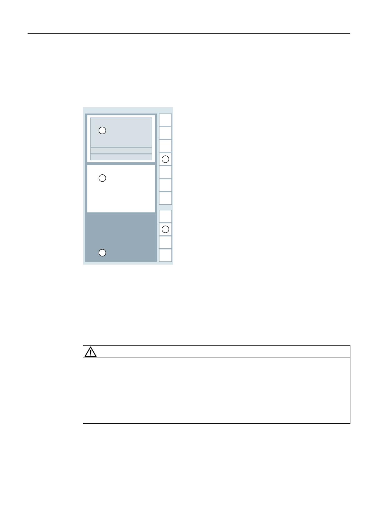
General settings
3.18 Activate and configure the Sidescreen window
Sidescreen structure
Several pages can be displayed on the sidescreen Only one page is active at a time. You can
toggle between the pages using the page selection keys.
The standard page contains a standard element to display widgets. You can configure
additional elements on this page.
① Widgets in the Siemens standard element
② Element (OEM) on a standard page
③ Page
④ Navigation bar for SINUMERIK Operate
⑤ Keys to select pages
Activation
WARNING
Unexpected machine movements caused by incorrect operation
Incorrect operation of devices with touch screen can result in unexpected machine
movements. This can result in personal injury or damage to property.
● Prevent unintentional incorrect operation by configuring the user interface appropriately,
e.g. by placing the buttons for starting and stopping machine components far enough apart.
● Configure the machine in such a way that safety-related functions are not operated with the
touch screen.
SINUMERIK Operate
50
Commissioning Manual, 12/2019, 6FC5397-1DP40-6BA3

General settings
3.18 Activate and configure the Sidescreen window
You activate the Sidescreen function via the following display machine data:
MD9114 $MM_SIDESCREEN
SINUMERIK Operate Sidescreen
= 1
Enables the additional Sidescreen display area of the Multitouch Panel (HD Ready or
Full HD).
= 2
Enables the sidescreen display area in HD Ready.
Enables the Display Manager (workbench) in full HD.
Note
Automatically hiding the Windows taskbar
In some situations SINUMERIK Operate is covered by the Windows taskbar on PCU/IPC. You
can hide the taskbar automatically to ensure proper user interface operation:
Right-click the taskbar and open the "Properties" (Windows 7) or "Taskbar settings"
(Windows 10) item in the menu. In the "Task bar" tab, select the option "Automatically hide the
taskbar" (Windows 7) or "Automatically hide the taskbar in desktop mode" (Windows 10).
Axis load display
Software option
To use this function, you need the software option:
"Evaluation of internal drive variables"
You can activate the detection of additional drive actual values for the axis load display in the
sidescreen:
MD36730 $MA_DRIVE_SIGNAL_TRACKING
Detection of additional drive actual values
= 1
$AA_LOAD: Drive load
$AA_POWER: Drive efficiency
$AA_TORQUE: Drive torque setpoint
$AA_CURR: Smoothed current actual value (quadrature-axis current) of the drive
Note
Detection for the axis load display is only possible if actual values are available from the drive.
Bar display for axis and spindle power
You can assign parameters for the bar display for the axis power using the following axis-
machine data:
MD53030 $MAS_AXIS_MAX_POWER
Maximum value of the axis power display
= 100
Default
Maximum permitted axis power in percent
The bar display is green in the range between 0 and the value of AXIS_MAX_POWER.
SINUMERIK Operate
Commissioning Manual, 12/2019, 6FC5397-1DP40-6BA3
51

General settings
3.18 Activate and configure the Sidescreen window
MD53031 $MAS_AXIS_POWER_RANGE
Display range of the axis power display
= 100
Default
Full-scale value for axis power display in percent
This value must be greater than or equal to AXIS_MAX_POWER. The bar display is red
in the range between the values of AXIS_MAX_POWER and
AXIS_POWER_RANGE.
You can assign parameters for the bar display for the spindle power using the following general
machine data:
MD51030 $MNS_SPIND_MAX_POWER
Maximum value of the spindle power display
= 100
Default
Maximum permitted spindle power in percent
The bar display is green in the range between 0 and the value of SPIND_MAX_POWER.
MD51031 $MNS_SPIND_POWER_RANGE
Display range of the spindle power display
= 100
Default
Full-scale value for spindle power display in percent
The value must be equal to or greater than SPIND_MAX_POWER. The bar display is
red in the range between the values of SPIND_MAX_POWER and SPIND_POW-
ER_RANGE.
3.18.2
Display Sidescreen ABC keyboard
Not only the standard windows but also the window for an ABC keyboard can be displayed in
the Sidescreen display of the Multitouch panel.
Procedure
1. Copy the sample file "slsidescreen.ini" from the directory
/siemens/sinumerik/hmi/template/sidescreen
2. Place the copy of the file in one of the following directories:
/oem/sinumerik/hmi/cfg or
/user/sinumerik/hmi/cfg
3. Open the copy and delete the comment sign ";" in front of the keyword PAGE002.
Note
The values of the attributes name and implementation must not be changed.
4. Save the setting.
The ABC keyboard can be selected after a run-up.
SINUMERIK Operate
52
Commissioning Manual, 12/2019, 6FC5397-1DP40-6BA3
General settings
3.18 Activate and configure the Sidescreen window
3.18.3
Display Sidescreen machine control panel
Not only the standard windows but also the window for machine control panel functions can be
displayed in the Sidescreen display of the Multitouch panel.
Multiple machine control panel windows can be optionally displayed.
The example of a machine control panel is displayed by the following procedure:
Procedure
1.
Copy the sample files "slsidescreenmcppageconfig.xml", "slsidescreenmcppage_eng.ts"
and the subdirectories of the icon files from the directory
/siemens/sinumerik/hmi/template/sidescreen/mcp/
The icon files are stored in the following subdirectories:
/ico1024 for HD Ready
/ico1920 for Full HD
2.
Place the copy of "slsidescreenmcppageconfig.xml" in one of the following directories:
/oem/sinumerik/hmi/proj or
/user/sinumerik/hmi/proj
3.
Place the copy of "slsidescreenmcppage_eng.ts" in one of the following directories:
/oem/sinumerik/hmi/lng or
/user/sinumerik/hmi/lng
Note
The TS file is automatically integrated by the system during startup.
4.
Save the icon files under the following path in one of the intended subdirectories:
/oem/sinumerik/hmi/ico or
/user/sinumerik/hmi/ico
Depending on the screen resolution, there are the following subdirectories:
/ico1024 for HD Ready
/ico1920 for Full HD
5.
Copy the sample file "slsidescreen.ini" from the directory
/siemens/sinumerik/hmi/template/sidescreen
6.
Place the copy of "slsidescreen.ini" in one of the following directories:
/oem/sinumerik/hmi/cfg or
/user/sinumerik/hmi/cfg
7.
Open the copy of the file "slsidescreen.ini", and delete the comment sign ";" in front of the
keyword PAGE003.
Multiple machine control panels are optionally available:
PAGE004, PAGE005 and PAGE006
Note
The values of the attributes name and implementation must not be changed.
8.
Save the setting.
The machine control panel can be selected after a run-up.
SINUMERIK Operate
Commissioning Manual, 12/2019, 6FC5397-1DP40-6BA3
53
General settings
3.18 Activate and configure the Sidescreen window
3.18.3.1
Configuring your own keys on the machine control panel
Own keys can also be displayed in the Sidescreen for the machine control panel. To do this, the
keys must be configured in the file "slsidescreenmcppageconfig.xml". The properties, position
of the keys and the headers are specified here.
Example of the file "slsidescreenmcppageconfig.xml"
<sideScreenControlPanel>
<mainBlock id="sideScreenMcpBlock1">
<block position="1" title="SPINDLE">
<row position="1">
<buttonGroup spacing="false" title="COOLANT">
<button position="1" text="ON" icon="slsidescreenmcp_cooling.png"
style="redStyle" title="Spindle">
<onPressed address="HmiUserKey1"/>
<active address="HmiUserLed1"/>
<disabled address="DisableHmiUserKey1"/>
</button>
<button position="2" text="OFF" icon="slsidescreenmcp_cooling_off.png">
<onPressed address="HmiUserKey2"/>
<active address="HmiUserLed2"/>
</button>
</buttonGroup>
</row>
</block>
</mainBlock>
************************************************************************
*** optional
***
************************************************************************
<mainBlock id="sideScreenMcpBlock2">
<.../>
</mainBlock>
<mainBlock id="sideScreenMcpBlock3">
<.../>
</mainBlock>
<mainBlock id="sideScreenMcpBlock4">
<.../>
</mainBlock>
<mainBlock id="sideScreenMcpBlockBelow1">
<.../>
</mainBlock>
<mainBlock id="sideScreenMcpBlockBelow2">
<.../>
</mainBlock>
<mainBlock id="sideScreenMcpBlockBelow3">
<.../>
</mainBlock>
<mainBlock id="sideScreenMcpBlockBelow4">
<.../>
</mainBlock>
</sideScreenControlPanel>
SINUMERIK Operate
54
Commissioning Manual, 12/2019, 6FC5397-1DP40-6BA3
General settings
3.18 Activate and configure the Sidescreen window
Adaptation options of the file "slsidescreenmcppageconfig.xml"
You can make the settings for your own keys in the <sideScreenControlPanel> tag:
Tag
Description
<mainBlock
Is the internal name of the machine control panel window
id="sideScreenMcpBlock1">
<block position="1"
A main section has any number of blocks.
title="SPINDLE">
position
Order of the blocks
title
Block header
<row position="1">
Each block has any number of lines.
position
Positioning of the lines
<buttonGroup
A key group combines two keys under one header.
spacing="false"
spacing
The property enables the display type of
title="COOLANT">
the keys to be determined:
together "false" or separate "true".
The default is separate.
title
All the keys in a key group have the same
header.
<button position="1"
Defines the key properties
text="ON"
position
Position of the key
icon="slsidescreenmcp_cooli
text
Labeling shown on the key
ng.png" style="redStyle"
title="Spindle">
icon
Icon of the key
The icon is displayed above the text la-
bel. If there is no labeling, then the icon
also takes up the labeling space.
style
Changes the backg2round color assigned
to the key
Possible values are:
"redStyle" for a red key
"greenStyle" for a green key
The default is "defaultStyle"
title
A key that does not belong to any group
can have its own header.
<onPressed
If the key is pressed, then the PLC bit is set to 1.
address="HmiUserKeyX"/>
The value remains at 1 as long as the key remains actuated.
With a brief press, the value remains at 1 for at least 300 ms.
address
Alias name "HmiUserKeyX" for the ad-
dressed PLC bit
Values of 1 to 64 are permitted for X.
HmiUserKey1 to HmiUserKey64 stand
for DB19.DBB404.0 to DB19.DBB411.7.
SINUMERIK Operate
Commissioning Manual, 12/2019, 6FC5397-1DP40-6BA3
55

General settings
3.18 Activate and configure the Sidescreen window
Tag
Description
<active
The key is shown as active (LED animation at the top edge of
address="HmiUserLedX"/>
the key).
address
Alias name of the PLC bit from which the
active identifier is derived
Values of 1 to 64 are permitted for X.
HmiUserLed1 to HmiUserLed64 stand
for DB19.DBB412.0 to DB19.DBB419.7.
<disabled address=
The key is shown as inactive (icon and text grayed out).
"DisableHmiUserKeyX"/>
address
Alias name of the PLC bit from which the
inactive identifier is derived.
Values of 1 to 64 are permitted for X.
DisableHmiUserKey1
to DisableHmiUserKey64 stand for
DB19.DB420.0 to DB19.DB427.7.
Store own icons
You can create your own icon files under one of the following paths:
/oem/sinumerik/hmi/ico or
/user/sinumerik/hmi/ico
Depending on the screen resolution, under the following subdirectories:
/ico1024 for HD Ready
/ico1920 for Full HD
Note
The icon file names must be the same as the names used in the XML file,
e.g. icon="slsidescreenmcp_cooling.png".
3.18.3.2
Create own translations of texts for the machine control panel
You can display all machine control panel texts in different languages. Translations are created
in the file "slsidescreenmcppage_xxx.ts".
"xxx" stands for a language code, e.g. "deu" for German, "eng" for English, and so on. You will
find the supported languages at "Supported languages (Page 512)"
SINUMERIK Operate
56
Commissioning Manual, 12/2019, 6FC5397-1DP40-6BA3
General settings
3.18 Activate and configure the Sidescreen window
Procedure
1. Create the file "slsidescreenmcppage_xxx.ts" with the desired language code in one of the
following directories:
/oem/sinumerik/hmi/lng or
/user/sinumerik/hmi/lng
2. Open the language file and insert the designations accordingly.
The following texts may be displayed in translation:
- All headers, e.g. title="COOLANT"
- All key labels e.g. text="ON"
3. Save the language file.
The translations are displayed after a run-up and the language has been changed.
Adaptation options of the file "slsidescreenmcppage_xxx.ts"
You can insert the translations in the <message> tag:
Tag
Description
<source>ON</source>
This is the language code of the original language.
<translation>ON</
This is the translation.
translation>
<chars>8</chars>
This is the maximum length of the translation.
The tag serves merely a note for the translator.
Example extract of the file "slsidescreenmcppage_eng.ts"
<message>
<source>ON</source>
<translation>EIN</translation>
<chars>8</chars>
</message>
3.18.4
Display sidescreen camera
In addition to the standard windows, up to two camera images can be displayed in the
sidescreen display of the Multitouch Panel.
Note
Compatibility
This function is not supported for an NCU 710.
SINUMERIK Operate
Commissioning Manual, 12/2019, 6FC5397-1DP40-6BA3
57
General settings
3.19 SINUMERIK Operate Display Manager
Procedure
1. Copy the sample file "slsidescreen.ini" from the directory
/siemens/sinumerik/hmi/template/sidescreen
2. Place the copy of the file in one of the following directories:
/oem/sinumerik/hmi/cfg or
/user/sinumerik/hmi/cfg
3. Open the copy and delete the comment sign ";" in front of the keyword ELEMENT009 for
Camera 1 and in front of ELEMENT010 for Camera 2.
Note
The values of the attributes name and implementation must not be changed.
4. Save the setting.
The cameras can be selected following power up.
Additional information
Additional information regarding setup of the cameras can be obtained in the online help
Commissioning functions and service.
3.19
SINUMERIK Operate Display Manager
3.19.1
Display configurations
Using the Display Manager and display configurations, it is possible to reduce
SINUMERIK Operate, in other words, run in less than full-screen mode, and to allocate the
space that is freed up to other applications. These applications are either standard Windows
applications (.EXE) or applications that belong to the Display Manager. Both types of
applications can also be developed by third parties using the OA Toolkit from
SINUMERIK Operate and integrated into a display configuration. To display the applications,
the screen is divided into "frames". Each frame may contain an application or a menu for
controlling an application displayed in another frame. Several screen segments or "Displays"
are possible and you can navigate between them during the program runtime. These displays
are combined into a display configuration. There may be multiple display configurations, for
example, for different screen resolutions.
A display configuration is defined either for a specific screen resolution or for a specific
operating unit. The available display configurations must be made known to the system in the
[displayConfigurations] section of the systemconfguration.ini file. The display
configuration itself is described in a separate configuration file.
SINUMERIK Operate
58
Commissioning Manual, 12/2019, 6FC5397-1DP40-6BA3
General settings
3.19 SINUMERIK Operate Display Manager
System requirement
The display manager is supported by the following systems:
● PC, PCU/IPC
● NCU 720 and NCU 730
Additional information
Additional information and examples relating to the Display Manager can be found in the
following documentation:
● Programming Manual Run MyScreens
● Operating Manual Universal/Turning/Milling/Grinding
Display configurations
'LVSOD\ FRQILJXUDWLRQ IRU
[
'LVSOD\
'LVSOD\
)UDPH
)UDPH
)UDPH
)UDPH
6LGHVFUHHQ
+0, 2SHUDWH
2QOLQH KHOS
+0, 2SHUDWH
)UDPH
&DPHUD
)UDPH
)UDPH
6ZLWFKRYHU PHQX
6ZLWFKRYHU PHQX
'LVSOD\ FRQILJXUDWLRQ IRU
[
'LVSOD\
)UDPH
)UDPH
6LGH
+0, 2SHUDWH
VFUHHQ
① Changing using the switchover menu
② Changing using TCU or the resolution switchover
SINUMERIK Operate
Commissioning Manual, 12/2019, 6FC5397-1DP40-6BA3
59

General settings
3.19 SINUMERIK Operate Display Manager
Example of the "systemconfiguration.ini" file
[displayConfigurations]
DC001 = res:=1366x768, file:=sldm_1366x768
DC002 = res:=1920x1080, file:=sldm_1920x1080
DC003 = tcu:=TCU1, file:=tcu1_layout
The example includes three display configurations. The names of the entries always begin with
the string "DC" followed by a sequential number. Each entry has a "file" property that points to
the file with the display configuration. The file can have any name. Like other configuration files,
it is also searched for in the cfg directories under siemens, addon, oem, and user. The ".ini" file
name extension does not have to be specified. The "res" property indicates the resolution to
which the respective display configuration applies. Different Display Manager configurations
can be displayed on various panels using property "tcu".
Note
Special aspects
● The size of the manufacturer layout must match the parameterized resolution, otherwise
display errors may occur on the user interface.
● If multiple display configurations are parameterized for a user interface, the display priority
"tcu" → "res" applies
● If no display configuration is applicable, the user interface is displayed in the full-screen
mode.
Activation
WARNING
Unexpected machine movements caused by incorrect operation
Incorrect operation of devices with touch screen can result in unexpected machine
movements. This can result in personal injury or damage to property.
● Prevent unintentional incorrect operation by configuring the user interface appropriately,
e.g. by placing the buttons for starting and stopping machine components far enough apart.
● Configure the machine in such a way that safety-related functions are not operated with the
touch screen.
To activate the SINUMERIK Operate Display Manager, the following display machine data
must be set.
MD9114 $MM_SIDESCREEN
SINUMERIK Operate Sidescreen
= 2
Enables the sidescreen display area in HD Ready.
Enables the Display Manager in full HD.
The default configurations used by the Display Manager for the two screen resolutions,
1920x1080 and 1366x768, are in the two files:
● sldm_1920x1080.ini
● sldm_1366x768.ini
SINUMERIK Operate
60
Commissioning Manual, 12/2019, 6FC5397-1DP40-6BA3

General settings
3.19 SINUMERIK Operate Display Manager
These files can be used as a template for custom display configurations. This section describes
how to create custom display configurations.
Note
Automatically hiding the Windows taskbar
In some situations SINUMERIK Operate is covered by the Windows taskbar on PCU/IPC. You
can hide the taskbar automatically to ensure proper user interface operation:
Right-click the taskbar and open the "Properties" (Windows 7) or "Taskbar settings"
(Windows 10) item in the menu. In the "Task bar" tab, select the option "Automatically hide the
taskbar" (Windows 7) or "Automatically hide the taskbar in desktop mode" (Windows 10).
3.19.2
Creating your own display configurations
3.19.2.1
Displays
One or more displays can be defined in the respective configuration file for each display
configuration. A name and a list of frames are specified for each of these displays. The frames
describe the division of the display into rectangular areas in which applications or menus can
be displayed.
Note
The order of configured displays is arbitrary.
Example
[displays]
DISPLAY001= name:=display_1, frames:="frame1, frame2, frame3"
DISPLAY002= name:=display_2, frames:="frame4, frame5, frame6, frame7"
…
Property
Meaning
name
Name of the display. Required, for example, for switching displays
frames
Contains a comma-separated list of frames that should be present on
this display to describe the layout of the display
enableMirrorMode
Activates (true) or deactivates (false) mirror mode for the display
(true|false)
When the mirror mode is activated, all frames of the display are dis-
played mirrored horizontally when the setMirrorMode (true) function is
called. Otherwise, the appearance of the frames remains unchanged
after calling the setMirrorMode (true) function.
"true" is default.
SINUMERIK Operate
Commissioning Manual, 12/2019, 6FC5397-1DP40-6BA3
61
General settings
3.19 SINUMERIK Operate Display Manager
Property
Meaning
onStartup
Contains a semicolon-separated list of actions to be performed when
the display first appears
The possible actions are described below.
onShow
Contains a semicolon-separated list of actions to be performed each
time the display fades
The possible actions are described below.
3.19.2.2
Frames
A frame is a container for applications or menus and primarily describes the desired position
and size of the application and menus in pixels. In addition, this is also where the application or
menu that should be displayed in the frame after the Display Manager starts is specified. The
applications that can be assigned to the frames are specified in
the systemconfiguration.ini file.
Example
[frames]
FRAME001= name:=frame1, x:=0, y:=0, width:=460, height:=970,
app:=mydialog
FRAME002= name:=frame2, x:=460, y:=0, width:=1460, height:=1080,
app:=OPERATE
FRAME003= name:=frame3, x:=0, y:=970, width:=460, height:=110,
menu:=mymenu
FRAME004= name:=frame4, x:=0, y:=0, width:=1280, height:=970,
app:=mydialog2, runableApps:="mydialog, mydialog2"
FRAME005= name:=frame5, x:=0, y:=970, width:=1280, height:=110,
menu:=menu2
FRAME006= name:=frame6, x:=1280, y:=0, width:=640, height:=480,
app:=OPERATE
FRAME007= name:=frame7, x:=1280, y:=480, width:=640, height:=600,
app:=mydialog3
…
If SINUMRIK Operate is to be displayed in a frame, the application name is specified as
"OPERATE". It should be noted that SINUMERIK Operate can only be used in certain sizes.
The currently supported sizes (in pixels) are:
●
640x480
●
760x505
●
800x480
●
800x600
●
1024x768
●
1024x1014
●
1080x810
●
1280x768
●
1280x800
SINUMERIK Operate
62
Commissioning Manual, 12/2019, 6FC5397-1DP40-6BA3
General settings
3.19 SINUMERIK Operate Display Manager
●
1280x1024
●
1300x768
●
1366x768
●
1440x1080
●
1454x1080
●
1854x1014
●
1854x1080
●
1920x1080
Property
Meaning
name
Name of the frame. Used in the frame list of the displays, for example
x, y, width, height
Absolute position (x, y), width and height of the frame in pixels
app
Application displayed in the frame the first time the frame is displayed.
runableApps
List of applications that may be displayed in this frame in case an appli-
cation is swapped.
menu
Menu that is displayed in the frame.
Ignored if "app" is used at the same time
SINUMERIK Operate
Commissioning Manual, 12/2019, 6FC5397-1DP40-6BA3
63

General settings
3.19 SINUMERIK Operate Display Manager
3.19.2.3
Menus
In addition to applications, menus can also be displayed in the frames of a display. These
menus are typically used to display certain applications in another frame or to switch displays.
A menu configuration consists of four parts:
● Description of the individual menu items (section [menuitems])
● Description of the look and feel of the menu items (section [menuitemstyle])
● Description of the menu structure (section [menus])
● Description of the look and feel of the menu (section [menustyle])
The [menuitems] section defines the menu items (keys/buttons). Each entry corresponds to
a key/button. The properties of the menu items can be configured.
The following properties are available:
Property
Meaning
name
Unique name of the menu item.
onClicked
Action to be triggered by clicking on this menu item. The actions that are
possible are described in the "Menu actions" section.
text
Text displayed on the menu item. Line breaks can be generated with \n
or %n.
textID
A text ID that references a language-dependent text. If the text can be
read, it replaces the text specified in the "text" property.
textContext
The context associated with the text ID. The context can also be specified
when configuring a menu or globally on the file level. Specifying a context
in the menu item overwrites any existing context information in the menu
or on the file level. Specifying a context in the menu overwrites any ex-
isting context information on the file level.
image
File name of the icon that is displayed on the menu item.
Special case for display button:
For buttons that are used to switch displays, the icon to be displayed on
the button can be generated automatically by the Display Manager. To do
this, you specify the name of the display to be switched with the file
extension ".auto" as the file name. A schematic drawing of the display is
then displayed as an icon. The stroke width and stroke color used for this
representation can be specified with the properties strokeWidth and stro-
keColor.
Display buttons have no text and no "imagePressed" icon.
strokeWidth1)
Stoke width of the schematic drawing for display buttons (see Property
image). Default: 1.
strokeColor1)
Color of the stokes of the schematic drawing for display buttons (see
Property image).
Default: Qt::lightGray
imagePressed
File name of the icon displayed on the menu item in the pressed state. As
an alternative to specifying this property, a file named "<image>_activa-
ted" is automatically used, if available; <image> is the name specified in
the "image" property.
SINUMERIK Operate
64
Commissioning Manual, 12/2019, 6FC5397-1DP40-6BA3

General settings
3.19 SINUMERIK Operate Display Manager
Property
Meaning
accessLevel
Access level from which the menu item is displayed:
System, Manufacturer, Service, Customer, Key_3, Key_2, Key_1, Key_0
or numerical equivalent (0-7)
Default: Key_0 (7)
menuItemStyle
Style of the menu item that defines all visual properties of the menu item.
Note
All of the properties described below can be specified for configuring the
respective menu items as well as for defining the MenuItemStyles. An
entry in the menu item overwrites the corresponding entry in the MenuI-
temStyle.
textSize2)
Font size
textAlignment2)
Alignment of the text of the menu item:
Left, Right, Top, Bottom, TopLeft, TopRight, BottomLeft, BottomRight
(analog Qt::Alignment)
You can also specify the values of the Qt flag field in hex (0x00) or dec-
imal.
Default: Qt::AlignCenter
imageAlignment2)
Alignment of the icon of the menu item:
Left, Right, Top, Bottom, TopLeft, TopRight, BottomLeft, BottomRight
(analog Qt::Alignment)
You can also specify the values of the Qt flag field in hex (0x00) or dec-
imal.
Default: Qt::AlignCenter
width2)
Width of the menu item in pixels.
Default behavior:
The menu items equally share the available space in the menu (horizon-
tal menu) less spacing, or are as wide as the menu minus the margin
(column menu).
For grid menus, the menu items equally share height and width.
height2)
Height of the menu item in pixels.
Default behavior:
The menu items equally share the available space in the menu (vertical
menu) less spacing, or are as tall as the menu minus the margin (row
menu).
For grid menus, the menu items equally share height and width.
color2)
Color of the menu item.
See paragraph "Color definitions".
Default: Qt::lightGray
pressedColor2)
Color of the menu item in the pressed state.
See paragraph "Color definitions".
Default: Qt::blue
textColor2)
Color of the menu item text
See paragraph "Color definitions".
Default: Qt::black
SINUMERIK Operate
Commissioning Manual, 12/2019, 6FC5397-1DP40-6BA3
65

General settings
3.19 SINUMERIK Operate Display Manager
Property
Meaning
pressedTextColor2)
Color of the menu item text in the pressed state of the menu item
See paragraph "Color definitions".
Default: Qt::white
borderWidth2)
Width of the border of the menu item in pixels
Default: 1.
borderColor2)
Color of the border of the menu item
See paragraph "Color definitions".
Default: Qt::darkGray
textRect2)
Rectangle relative to the menu item (widget coordinate system, i.e. Top-
Left of the menu item is coordinate 0,0) in which the text is aligned.
The following should be specified:
x, y, width, height. For example, textRect:="0,10,40,30" or tex-
tRect:=0/10/40/30 or textRect:=0 10 40 30
Note the required quotes when commas are used as delimiters, because
commas are also the separator between the properties.
Default: The rectangle within the border; for borderWidth = 0 this is the
rectangle of the complete menu item.
imageRect2)
Rectangle relative to the menu item (widget coordinate system, i.e. Top-
Left of the menu item is coordinate 0,0) in which the icon is aligned.
The following should be specified:
x, y, width, height. For example, imageRect:="0,10,40,30" or image-
Rect:=0/10/40/30 or imageRect:=0 10 40 30
Note the required quotes when commas are used as delimiters, because
commas are also the separator between the properties.
Default: The rectangle within the border; for borderWidth = 0 this is the
rectangle of the complete menu item.
1) Only relevant for display buttons
2) Applies to menuItem and menuItemStyle
Example 1
[menuitems]
MENUITEM001= name:=menuitem1, onClicked:=showDisplay(display1),
text:="Display1"
MENUITEM002= name:=menuitem2, onClicked:=showDisplay(display2),
text:="Display2", accessLevel:=Customer, width:=100
MENUITEM003= name:=miPdf, menuItemStyle:=misMenu,
onClicked:="showApp(defaultFrame, appPdf)", image:=dm_pdf.png,
text:="PDF"
MENUITEM004= name:=miBrowser, menuItemStyle:=misMenu,
onClicked:="showApp(defaultFrame, appBrowser)",
image:=dm_browser.png, textID:=TEXT_ID_BROWSER
In the [menuitemstyles] section, styles can be defined for menu items in which all visual
properties of a menu item are defined. The individual properties can in turn be overwritten in the
menu item. The summary of all visual attributes saves typing work, because you usually have
many menu items that generally should all look the same. If a property should then be different
for a menu item, it can be overwritten individually.
SINUMERIK Operate
66
Commissioning Manual, 12/2019, 6FC5397-1DP40-6BA3
General settings
3.19 SINUMERIK Operate Display Manager
Description of MenuItemStyle properties: See above.
Example 2
[menuitemstyles]
MENUITEMSTYLE001= name:=misMenu, textSize:=10,
textAlignment:=bottom, imageAlignment:=top, color:=37/53/63,
textColor:=153/173/185, pressedColor:=52/87/140,
pressedTextColor:=White, borderColor:=37/53/63,
pressedBorderColor:=52/87/140, borderWidth:=5, height:=66, width:=66
For unspecified properties, the corresponding default values (see above) take effect.
In the [menus] section, one or more menuItems are combined into a menu. This is done using
the menuItems property, which contains a list of the menu items (buttons/buttons) to be
displayed in a certain menu. The available properties are listed in the following table:
Property
Meaning
menuItems
List of menu items.
Comma-separated list of menu item names
With the "grid" menu layout, the menu items are specified as follows to
determine their position within the menu:
menuItem(row, col, rowSpan=1, colSpan=1)
The indexes "row" and "col" start with the value 0.
Specifying "rowSpan" and "colSpan" is optional, default value is 1 (anal-
ogous to QGridLayout::addWidget ())
With the "row" or "col" menu layout, you can also use the specification of
spacing (pixel) and stretch (factor = 0):
● Spacing inserts "int" pixels of additional spacing between the menu
items (analogous to QBoxLayout::addSpacing ())
● Stretch inserts a stretchable additional distance between the menu
items, an expansion factor can be optionally specified (analogous to
QBoxLayout::addStretch ())
defaultFrame
Name of the frame on which the menu items of the menu are to act and
that use the "defaultFrame" string as target specification in the showApp
statement. This allows menu items to be reused in multiple menus.
textContext
The context for the text ID of the menu items (see above).
itemAccessLevel /
Access level from which the menu items are displayed:
accessLevel
System, Manufacturer, Service, Customer, Key_3, Key_2, Key_1, Key_0
or numerical equivalent (0-7)
Default: Key_0 (7)
menuStyle
Style of the menu.
Sets all visual properties
Note
All of the properties described below can be specified for configuring the
respective menus as well as for defining the MenuStyles. An entry in the
menu overwrites the corresponding entry in the MenuStyle.
SINUMERIK Operate
Commissioning Manual, 12/2019, 6FC5397-1DP40-6BA3
67
General settings
3.19 SINUMERIK Operate Display Manager
Property
Meaning
layout1)
Alignment of menu items:
"row", "col" or "grid". With a "row" or "col" layout, the menu items are
aligned horizontally in a row or vertically in a column.
With a "grid" layout, the menu items are arranged in a grid.
Default: "row"
margin1)
Margin between the menu items and the outer edge of the menu.
Value in pixels, (analogous to QBoxLayout::setMargin() or QGridLay-
out::setContentsMargin() (all 4 directions))
Default: 1.
spacing1)
Spacing between the menu items.
Value in pixels, (analogous to QBoxLayout::setSpacing() or QGridLay-
out::setSpacing())
Default: 1.
color/
Color (backg2round color) of the menu.
backg2roundColor1)
See paragraph "Color definitions".
Default: Qt::gray
1) Applies to menu and menuStyle
Example 3
[menus]
MENU001= name:=menu1, menuItems:="menuitem1, menuitem2, menuitem3"
MENU002= name:=menu2, orientation:=vertical, margin:=2, spacing:=2,
items:="menuitem4, menuitem5, spacing(50), menuitem6, menuitem7,
stretch()", itemHeight:=100
MENU003= name:=mMenuOben, menuStyle:=msMenu, defaultFrame:=fTop,
items:="miPdf, miBrowser, spacing(10), miOperate, stretch(),
miMaximize"
MENU004= name:=mGridMenu, menuStyle:=msGrid, defaultFrame:=fBottom,
items:="miMachine(0,0), miProgram(0,1), miProgramManager(0,2),
miDiagnosis(0,3), miPdf(1,0), miBrowser(1,1), mOperate(1,2,1,2),
miMirror(0,3,2,1)"
In the [menustyles] section, styles can be defined for menus in which all visual properties
of a menu are defined. The individual properties can in turn be overwritten during the
configuration of the respective menu.
Description of the menu style properties: See above.
Example 4
[menustyles]
MENUSTYLE001= name:=msVerticalMenu, color:=59/76/88, layout:=column,
margin:=0, spacing:=1
MENUSTYLE023= name:=msGrid, color:=59/76/88, layout:=grid,
margin:=10, spacing:=1
Finally, the menu still needs to be assigned to a frame. The "menu" frame property is used for
this:
[frames]
SINUMERIK Operate
68
Commissioning Manual, 12/2019, 6FC5397-1DP40-6BA3
General settings
3.19 SINUMERIK Operate Display Manager
FRAME003= name:=frame3, x:=0, y:=970, width:=460, height:=110,
menu:=menu2
SINUMERIK Operate
Commissioning Manual, 12/2019, 6FC5397-1DP40-6BA3
69

General settings
3.19 SINUMERIK Operate Display Manager
3.19.2.4
Menu actions
The actions to be performed when a menu item is pressed are defined in the onClicked property
of the menu items. This property can include one or more command statements (separated by
semicolons), which are executed one after the other.
The following commands are available:
Command
Meaning
showDisplay(displayname)
Switches to the display named displayname
The target display must be configured in the same dis-
play configuration file.
showApp(framename, appname)
Displays application appname in the framename frame
If the application is already visible in another frame of
the display, it is moved from there to the frame specified
here. If possible, the freed frame is filled with the appli-
cation displaced from framename. If this happens, it is
referred to as application swapping. Which applications
can be displayed in the released frame is specified in the
"runableApps" property of this frame.
You can prefix the frame name with a display name
(displayname.framename) and change the frame
assignment in hidden displays.
Instead of appname, you can also
specify framename.currentApp
or displayname.framename.currentApp.
showApp() then moves the displayed application in
the framename or displayname.framename frame
into the specified frame.
showPopup(framename, appname)
Displays application appname in the framename frame
as popup window.
It is not permissible that frame framename belongs to a
display, i.e. it is not specified in the Frames attribute for
an existing display. It is automatically displayed with
the showPopup() call and placed over the currently
active display.
The only applications allowed are the applications cre-
ated on the basis of the SlGfwSideScreenDialog
class. SINUMERIK Operate and OEM frame applica-
tions cannot be displayed as popups. If you use an ap-
plication that was developed based on
the SlGfwSideScreenDialog class as a popup, you
need to declare its window as a TopLevel window,
which means the Qt::WindowStaysOnTopHint bit must
be set in the windowFlags().
Only one popup can be open at a time.
hidePopup(appname)
Hides an application displayed with showPopup()
or togglePopup()
togglePopup(framename, appname)
Displays application appname in the framename frame
as popup window. If the appname application is already
displayed as popup window, then it is hidden again.
showMenu(framename, menuname)
Shows the menuname menu in the framename frame.
SINUMERIK Operate
70
Commissioning Manual, 12/2019, 6FC5397-1DP40-6BA3