SINUMERIK 840D sl. Basesoftware and operating software. Manual (2019) - page 4
Data backup
13.5 Creating an archive with original data
Procedure
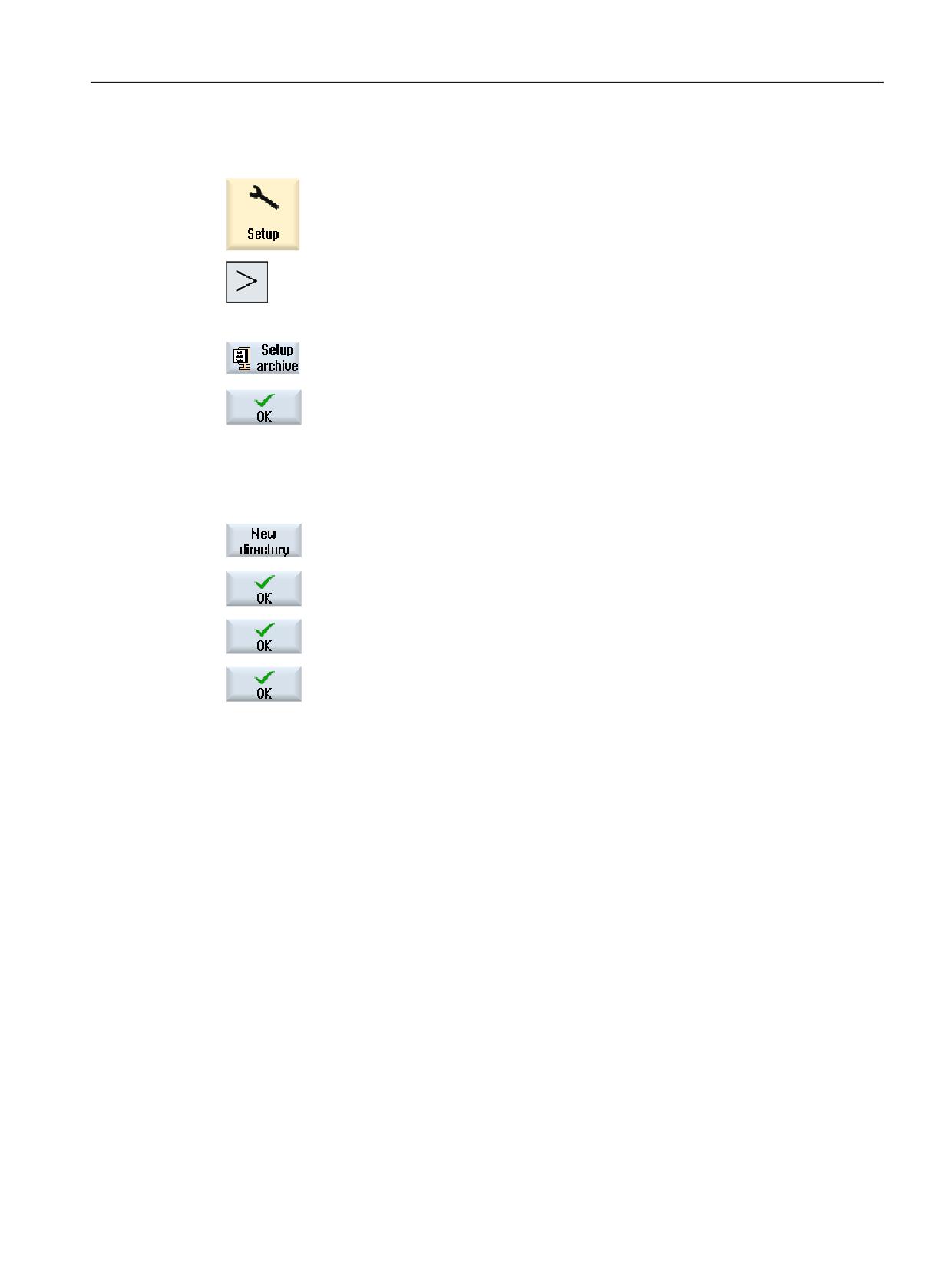
1.
Select the "Start-up" operating area.
Press the menu forward key.
2.
Press the "Start-up archive" softkey.
The "Start-up" window opens.
3.
Activate "Create PLC hardware upgrade archive (SDBs only)" and press
the "OK" softkey.
The "Create PLC hardware upgrade archive (SDBs only): Select Storage
Location" window opens.
4.
Select the desired storage location in the displayed data tree.
- OR -
Press the "New directory" softkey to create a separate directory.
The "New Directory" window opens.
5.
Enter the required name and press the "OK" softkey.
The directory is created below the created folder.
6.
Press the "OK" softkey.
The "Generate Archive: Name" window opens.
The file type of the archive is ARC and is displayed in the window. Enter
the desired name and press the "OK" softkey.
The archive is generated and stored in the selected directory.
13.5
Creating an archive with original data
You can select this type of start-up in order to save the original status of the control. The files
are archived in the "original.arc" file.
The file is stored on the CompactFlash card in the Archives/Manufacturer directory.
If there is no "original.arc" file in the directory, it is recommended that an archive be generated
from the data of the original control state as delivered.
As for "Create start-up", control components can be saved individually or jointly.
Requirement
In order to save NC data, you require access level 2 (service).
To back up programs/workpieces, you require access level 6 (keyswitch position 1).
SINUMERIK Operate
Commissioning Manual, 12/2019, 6FC5397-1DP40-6BA3
209

Data backup
13.5 Creating an archive with original data
Data of the control components
Control components
Data
NC data
Machine data
Setting data
Option data
Global (GUD) and local (LUD) user data
Tool and magazine data
Protection zone data
R parameters
Zero offsets
Compensation data
Workpieces, part programs and subprograms
Standard and user cycles
Definitions and macros
With compensation data
● QEC - quadrant error compensation
● CEC - operation/angularity compensation
● EEC - leadscrew pitch / encoder error compensation
● It only makes sense to archive machine-specific compensation
data if the series start-up file is reloaded into the same control.
With compile cycles
Compile cycles (*.elf) are displayed if compile cycles are available.
PLC data (including CP)
OB (organization blocks)
FB (function blocks)
SFB (system function blocks)
FC (functions)
SFC (system functions)
DB (data blocks)
SDB (system data blocks)
HMI data, all
HMI data, selection:
Cycle storage
Definitions and cycles
Texts
User texts, alarm texts
Templates
Individual templates, workpiece templates
Applications
HMI applications, OEM applications
Engineering data
Engineering data
Configuration
Configurations, incl. display machine data
Help
Help files
Version data
Version data
Logs
Error logs
User views
Individually compiled tables with selected machine and setting data.
Dictionaries
Dictionaries
Programs on local drive/
Programs contained in the user memory area.
NC Extend
Note: Remember that the user data may be large in volume and any
archive file that you create from it will require more memory.
SINUMERIK Operate
210
Commissioning Manual, 12/2019, 6FC5397-1DP40-6BA3
Data backup
13.6 Reading in an archive with original data
Procedure
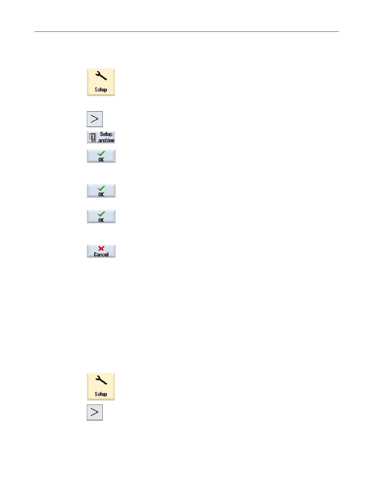
1.
Select the "Start-up" operating area.
2.
Press the menu forward key.
3.
Press the "Start-up archive" softkey.
The "Start-up" window opens.
4.
Activate the "Create archive of original status" checkbox and press the
"OK" softkey.
The "Create Start-up for Original Status" window opens.
5.
Select the desired control components.
6.
When required, enter a comment into the field as well as your name and
the date of creation - and then press the "OK" softkey.
A warning is output if an "original.arc" archive file already exists.
7.
Press the "OK" softkey to overwrite the file.
A new archive file is generated and stored in the Archives/Manufacturer
directory.
- OR -
Press the "Cancel" softkey so that the existing file is not overwritten.
13.6
Reading in an archive with original data
The data of the original controller state is stored in the "original.arc" file. If you want to restore
the controller to the as-delivered state, you can read in the original data archive.
Precondition
You require access level 2 (service).
Procedure
1.
Select the "Start-up" operating area.
2.
Press the menu forward key.
SINUMERIK Operate
Commissioning Manual, 12/2019, 6FC5397-1DP40-6BA3
211

Data backup
13.8 Serial interface (V24 / RS232)
3.
Press the "Start-up archive" softkey.
The "Start-up" window opens.
4.
Activate the "Read in archive of original status" checkbox and press the
"OK" softkey.
SINUMERIK Operate automatically accesses the "original.arc" file.
A window opens prompting whether you want to perform a start-up.
5.
Press the "OK" softkey.
The read-in process is started and a progress message box is displayed
in the window.
Any errors that occur are then displayed in the "Write Error Log for Ar-
chive" window.
13.7
Generating the complete archive
You have the option of generating an archive of the complete data of your control on an external
storage medium that you can provide to Technical Support for diagnostic purposes.
Procedure
1. Insert the storage medium in the USB port.
2. Press the key combination <Ctrl> + <Alt> + S.
All data required for diagnostics are compiled in an archive.
Note:
Operator control is not possible while the archive is being generated.
3. You will receive a message once archiving has been completed.
The system assigns an archive name and this is: CompletArchiv<Date>_<Time>.arc.
The dialog box is closed and you can re-operate the control.
13.8
Serial interface (V24 / RS232)
13.8.1
Reading-in and reading-out archives via a serial interface
You have the option of reading out and reading in archives in the "Program manager" operating
area as well as in the "Startup" operating area via the V24 serial interface.
SINUMERIK Operate
212
Commissioning Manual, 12/2019, 6FC5397-1DP40-6BA3

Data backup
13.8 Serial interface (V24 / RS232)
Availability of the V24 serial interface
If you want to change the availability of the V24 interface, you can adjust the following
parameters in file "slpmconfig.ini”:
Parameters
Description
[V24]
Describes the section in which the relevant setting parameters
are located.
useV24
Setting for the availability of the V24 serial interface
= true
Interface and softkeys are available (de-
fault)
= false
Interface and softkeys are not available
Storage of file "slpmconfig.ini"
The template of the file "slpmconfig.ini" for SINUMERIK Operate is stored in the following
directory:
<Installation path>/siemens/sinumerik/hmi/template/cfg
Copy the file to one of the following directories:
<Installation path>/user/sinumerik/hmi/cfg
<Installation path>/oem/sinumerik/hmi/cfg
Note
If you want to achieve a better overview of the changes you have made yourself, simply delete
the unchanged parameters from the file copy "slpmconfig.ini".
Reading-out archives
The files to be sent (directories, individual files) are zipped in an archive (*.arc). If you send an
archive (*.arc), this is sent directly without being additionally zipped. If you have selected an
archive (*.arc) together with an additional file (e.g. directory), then these are zipped into a new
archive and are then sent.
Reading-in archives
Use interface V24 if you want to read in archives. They are transferred and then subsequently
unzipped.
Note
Reading in commissioning archives
When you read in a commissioning archive via the V24 interface, then this is immediately
activated.
SINUMERIK Operate
Commissioning Manual, 12/2019, 6FC5397-1DP40-6BA3
213
Data backup
13.8 Serial interface (V24 / RS232)
Externally processing the punched tape format
If you wish to externally process an archive, then generate this in the punched tape format.
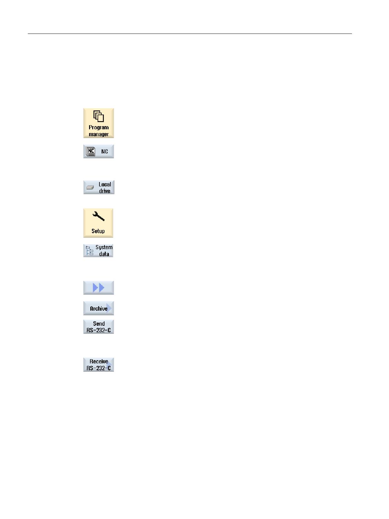
Procedure
1.
Select the "Program manager" operating area, and press the "NC"
or "Local. drive" softkey.
- OR -
Select the "Startup" operating area and press the "System data"
softkey.
Reading-out archives
2.
Select the directories or the files that you wish to send to V24.
3.
Press the ">>" and "Archive" softkeys.
4.
Press the "V24 send" softkey.
- OR -
Reading in an archive
Press the "V24 receive" softkey if you wish to read-in files via V24.
SINUMERIK Operate
214
Commissioning Manual, 12/2019, 6FC5397-1DP40-6BA3
Data backup
13.8 Serial interface (V24 / RS232)
13.8.2
Setting interface parameters
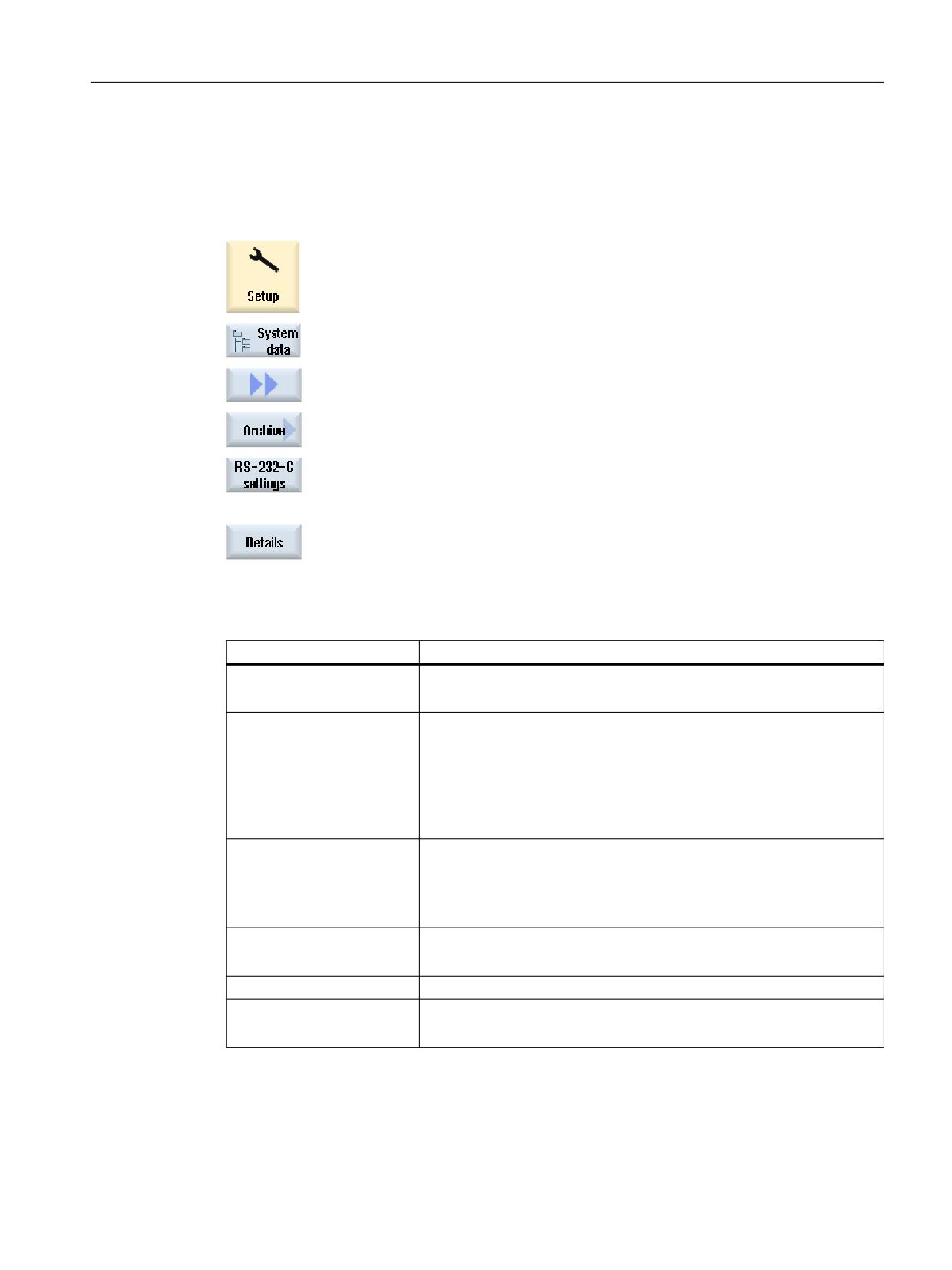
Procedure
1.
Select the "Start-up" operating area.
2.
Press the "System data" softkey.
3.
Press the ">>" and "Archive" softkeys.
4.
Select the "RS-232-C settings" softkey.
The "Interface: RS-232-C" window is opened and the interface
settings are displayed.
5.
Press the "Details" softkey if you wish to view and process addi-
tional settings for the interface.
RS-232-C settings
Parameter
Meaning
Protocol
The following protocol is supported for transfer via the RS-232-C:
● RTS/CTS
Transfer
It is also possible to use a secure protocol for data transfer (ZMODEM
protocol).
● Normal (default setting)
● Secure
For the selected interface, secure data transfer is set in conjunction
with handshake RTS/CTS.
Baud rate
Transfer rate: The baud rate that can be used depends on the connected
device, the cable length and the general electrical conditions.
●
19200 (default setting, maximum baud rate for NCU (Linux))
●
115200 (maximum baud rate for PC/PCU (Windows))
Archive format
● Punched tape
● Binary format (PC format)
RS-232-C settings (details)
Interface
● COM1
● COM2 (only relevant for SINUMERIK Operate on PC)
SINUMERIK Operate
Commissioning Manual, 12/2019, 6FC5397-1DP40-6BA3
215

Data backup
13.9 Backing up setup data
Parameter
Meaning
Parity
Parity bits are used for error detection: The parity bits are added to the
coded characters to make the number of positions set to "1" an uneven
number (uneven parity) or to an even number (even parity).
● None (default setting)
● Odd
● Even
Stop bits
Number of stop bits for asynchronous data transfer.
●
1 (default setting)
Data bits
Number of data bits for asynchronous data transfer.
●
8 bits (default setting)
XON (hex)
Only for punched tape format
XOFF (hex)
Only for punched tape format
End of data transfer (hex)
Only for punched tape format
Stop with end of data transfer character
The default setting for the end of data transfer character is (HEX) 1A.
Time monitoring (sec)
Time monitoring
For data transfer problems or at the end of data transfer (without end of
data transfer character) data transfer is interrupted after the specified
number of seconds.
The time monitoring is controlled by a time generator (clock) that is star-
ted with the first character and is reset with each transferred character.
The time monitoring can be set (seconds).
13.9
Backing up setup data
Setting for "Backup setup data"
The "Backup setup data" function should only be used if MD11280 $MN_WPD_INI_MODE is
set to 1 (default setting). Otherwise, when the NC is started for the first time after selecting the
part program, a file with the same name with the ".ini" extension would be automatically
executed.
SINUMERIK Operate
216
Commissioning Manual, 12/2019, 6FC5397-1DP40-6BA3

Data backup
13.10 Network settings
Machine data:
MD11280 $MN_WPD_INI_MODE
Processing mode of ini files in the workpiece directory
= 1
When the NC is started for the first time, after the workpiece selection, ini files with the name
of the selected part program and the following extensions are executed:
CEC
Sag compensation (Cross Error Compensation)
GUD
User data (Global User Data)
PRO
Protection zones
RPA
R parameters
SEA
Value assignments (Setting Data Active)
TMA
Magazine data (Tool Magazine Active)
TOA
Tool offsets (Tool Offset Active)
UFR
Work offsets (User Frame)
13.10
Network settings
Activating
By default, the network settings cannot be backed up. The archiving of the network settings
must be enabled:
1. Copy the "slpmconfig.ini" file from the /siemens/sinumerik/hmi/template/cfg directory.
2. Store the file in the /oem/sinumerik/hmi/cfg or /user/sinumerik/hmi/cfg directory.
3. Open the file and enter the following for [SeriesSetup]:
SupportNetworkSettings=true
4. Restart SINUMERIK Operate.
Note
This setting also affects the creation of a complete standard archive using Ctrl+Alt+S or Ctrl
+Alt+C.
Additional information
A description of the various key combinations is provided in the
Operating Manual Universal/Turning/Milling/Grinding
SINUMERIK Operate
Commissioning Manual, 12/2019, 6FC5397-1DP40-6BA3
217
Data backup
13.10 Network settings
Restrictions
● The leases files are not saved:
- /system/etc/udhcpd-eth0.leases
- /system/etc/udhcpd-ibn0.leases
● A configuration in the system network must be based on the DNS name rather than IP
addresses.
Basic procedure
● Backup of network settings
After activation, the network settings can also be backed up when a commissioning archive
is created when a check mark is set, see Creating a start-up archive (Page 204).
● Importing network settings
The saved archives can be imported in the same manner as a commissioning archive,
see Reading-in a start-up archive (Page 207).
Note
Importing network settings for replacement components
Disconnect the replacement components from the system network before you import the
saved network settings.
NCU
With SINUMERIK Operate on the NCU, the following NCU settings are backed up:
● /user/system/etc/basesys.ini
● /user/common/tcu (complete directory)
Note
The network settings of an NCU can only be backed up and read on the PG/PC via
SINUMERIK Operate.
The NC address in mmc.ini on the PC/PG is 192.168.215.1.
SINUMERIK Operate
218
Commissioning Manual, 12/2019, 6FC5397-1DP40-6BA3
Data backup
13.10 Network settings
PCU
The following PCU settings and, if applicable, NCU settings are saved with
SINUMERIK Operate on the PCU:
● PCU
- /user/system/etc/basesys.ini
- mmc.ini for SINUMERIK Operate
● NCU (when present as master)
- /user/system/etc/basesys.ini
- /user/common/tcu (complete directory)
The following archives are created:
● <Archive_name>_pcu.arc
● <Archive_name>_ncu.arc
Importing an archive for a configuration with NCU as master (DHCP) and PCU (on_low):
1. Import the archive for Archivename_pcu.arc on a PCU with SINUMERIK Operate.
2. Depending on the replaced parts of the NCU, note the following:
- If the NCU was not replaced, the system restarts.
- If the NCU has been replaced, <Archive_name>_ncu.arc must be read in via a separate
user interface with the X127 interface.
SINUMERIK Operate
Commissioning Manual, 12/2019, 6FC5397-1DP40-6BA3
219
Data backup
13.10 Network settings
SINUMERIK Operate
220
Commissioning Manual, 12/2019, 6FC5397-1DP40-6BA3
Configuring the network
14
Overview
If you wish to perform network settings in SINUMERIK Operate, you have the following options:
● The Start-up operating area allows you to set up all of the basic configurations for the plant
and company networks (see Section "Displaying the network overview (Page 221)").
● The Diagnostics operating area gives you an effective overview of all available network
adapters and allows you to assign and check settings for the company network or the DHCP
server, for example (see Section "Configuring TCP/IP diagnostics (Page 242)").
14.1
Displaying the network overview
All the available interfaces and their network settings are listed in the "Overview of the network
settings" window. For example, the IP addresses, subnet masks and MAC addresses for the
company and system network are displayed here. You have the option of editing the settings.
Procedure
1.
Select the "Start-up" operating area.
2.
Press the "Menu forward" key.
3.
Press the "Network" softkey.
The "Overview of the Network Settings" window opens.
4.
Press the "Change" softkey to edit settings.
See also
Settings of the system network (Page 222)
Settings of the factory network (Page 225)
Saving network settings (Page 227)
SINUMERIK Operate
Commissioning Manual, 12/2019, 6FC5397-1DP40-6BA3
221

Configuring the network
14.2 Settings of the system network
14.2
Settings of the system network
The configuration for the DHCP server, the routing, active protocols, for DNS servers and other
properties of the system network is performed in the "Settings of the system network" window.
Setting
Description
DHCP activated
Activates or deactivates the DHCP mode for the
system network. This automatically assigns IP ad-
dresses to the nodes in the system network.
DHCP server synchronization mode
Activates or deactivates the DHCP server synchro-
nization mode. If this setting is active, then the
DHCP servers synchronize themselves in the sys-
tem network (X120) so that only one of them ac-
tively assigns addresses. This makes it possible to
operate multiple NCUs or PCUs concurrently with-
out having to adjust the network settings.
The DHCP servers that are not active go into
"standby" mode; in this mode they regularly get the
current address data and TCU data from the active
server so that if the active server fails, a standby
server can take over the active role without data
loss.
● With the "Master priority" setting you can
influence the synchronization in such a manner
that the server with the "Master" setting is
always the active server (it must be active in
the network). This means that in the normal
situation, deterministically the same control is
always the DHCP server and you can find the
actual address data and the TCU data there.
"Master priority" must only be set for a single
DHCP server in the system network.
● The settings "Low priority " and "High priority"
can be used to specify which DHCP server
takes precedence as the active server. A
DHCP server with low priority is then only used
as active server when a server with high priority
cannot be found in the network.
Default: "High priority"
DHCP address range
Specifies the range for DHCP addresses. The
range starts at the address specified at "Start" and
ends at the address entered at "End". The result-
ing range of numbers has the following default set-
ting:
Start address = first address in the system network
End address = start address + 10 or + 2 (if less than
16 addresses are available)
SINUMERIK Operate
222
Commissioning Manual, 12/2019, 6FC5397-1DP40-6BA3

Configuring the network
14.2 Settings of the system network
Setting
Description
Timeout when waiting for master
Specifies a maximum waiting time (in seconds) for
the response of the master server (see DHCP
server synchronization mode). After this time elap-
ses, the server itself becomes the active server.
This additional pause makes it possible for the in-
tended DHCP master to become the active DHCP
server without displacement even if it is shortly
switched on thereafter, or takes longer to boot than
other controls.
Default: 120 seconds
Host name
Assigns the DHCP server a fixed host name. In this
way, the server can also be addressed via the host
name and not only via the IP address.
Because the host name is also used as DNS
name, it must satisfy the corresponding require-
ments of the RFC:
● ASCII letters (a-z, A-Z), digits (0-9) and '-'
● maximum 63 characters
DNS domain
This is used to specify the Top Level Domain (TLD)
name used in the system network. The DNS server
of the NCU assigns names to the devices in the
system network in this zone. Name requests for all
other zones are forwarded to an external name
server in the company network.
The "local" default setting recommended by the
RFC1035 is used for local networks, to avoid con-
flicts with globally defined domain names. As a
rule, this default setting is sufficient.
PN station name
A separate machine name can be defined here for
PROFINET purposes. This is used at the ERTEC
interface (when available), transferred to the ER-
TEC system program and also used by DCP at this
network interface.
Station name
This string is used for the SINUMERIK-specific
OID mcSinumerikMIB.mcSinumerikMiscStation.
The value is the name of a station to which the
device belongs. Devices with the same station
name can therefore be identified as belonging to-
gether. This is for information purposes only.
Location
This string is used for the standard OID SNMPv2-
MIB::sysLocation. If required, a location can be
specified here which can be called by an SNMP
client. This is for information purposes only.
Contact person
This string is used for the standard OID SNMPv2-
MIB::sysContact. If required, a contact address
can be specified here which can be called by an
SNMP client. This is for information purposes only.
SINUMERIK Operate
Commissioning Manual, 12/2019, 6FC5397-1DP40-6BA3
223

Configuring the network
14.2 Settings of the system network
Setting
Description
Function
This string is used for the Siemens Industry-spe-
cific OID automationSystemIdent.automation-
FunctionTag. If required, a function designation
can be specified here which can be called by an
SNMP client. This is for information purposes only.
Fixed domain
Defines an additional DNS domain name (suffix for
DNS queries). This is of especial interest when the
DHCP server is switched off at the X120 because
this cannot set the "local" domain, but it is required
for some DNS queries (e.g. for machine control
panels).
Fixed DNS server
Specifies up to three DNS servers that are to be
used by the DHCP server. This is of especial in-
terest when the DHCP server is switched off at the
X120 because this is also a DNS server or deter-
mines DNS servers in the network.
Routing
● Routing X120/X127 -> X130
Specifies whether the routing of packets from the
system network (X120) and/or service connection
X127 to the company network (X130) is active:
● Released: Activates the routing for X120 and
X127
● Disabled: Deactivates the routing for X120 and
X127
● X127: Activates only the routing from X127 to
the company network
● X120: Activates only the routing from the
system network to the company network
● Routing X127 -> X120
Activates or deactivates the NAT routing of pack-
ets from the service connection X127 to the sys-
tem network (X120).
● Routing X120 -> X127
Activates or deactivates the routing of packets
from the system network (X120) to the service
connection X127. This is normally prohibited by
the firewall.
Note that there is no NAT and the sender must
ensure that packets to the PG or service PC at
X127 with address 192.168.215.x actually reach
the NCU to which the device is connected.
Active protocols
Specifies which protocols are to be used in the
system network. "DCP" (Discovery and Basic Con-
figuration Protocol) and "LLDP" (Link Layer Dis-
covery Protocol) are available for selection. The
appropriate active protocol is also used for the
service connection X127 at the NCU.
SINUMERIK Operate
224
Commissioning Manual, 12/2019, 6FC5397-1DP40-6BA3
Configuring the network
14.3 Settings of the factory network
Procedure
1.
The network overview is open.
2.
Press the "System network" softkey.
The "Settings of the System Network" window opens.
3.
Press the "Change" softkey to edit settings.
4.
Press the "Reset DHCP server" softkey to return the current settings of
the DHCP server to the original settings.
5.
Press the "Distribute DHCP data" softkey to synchronize the settings
with all nodes in the system network.
Note
You can only use the "Reset DHCP server" and "Distribute DHCP data" softkeys with a
connection to the active DHCP server.
14.3
Settings of the factory network
The network interface, active protocols and firewall exceptions of the company network are
configured in the "Settings of the company network" window.
Setting
Description
Gateway
If this value is not empty, the host specified there is
used as the default gateway, which means that all
IP packets that cannot be directly assigned are
sent there for routing.
DNS server
If DNS name servers are specified here (maximum
three), then they must be used to resolve symbolic
host names, i.e. at most of the points where an IP
address is expected, a computer name can also be
used instead.
The name server setting is also sent to its DHCP
clients (TCU, PG) via the DHCP server of the NCU,
so that they can also work with symbolic names.
Time server
Here you can specify up to three NTP servers
(UDP/123) that can be used by the NTPD on the
NCU for time synchronization.
SINUMERIK Operate
Commissioning Manual, 12/2019, 6FC5397-1DP40-6BA3
225

Configuring the network
14.3 Settings of the factory network
Setting
Description
Host name
Here you can define a name for the local host. This
manually assigned name takes priority over all oth-
er names.
The host name is determined in the following order:
● This entry (identical to the host name from the
basesys.ini file)
● A name received from the DHCP server
(reverse DNS lookup, i.e. which name belongs
to the received IP address)
● Default name ("NONAME_...")
Because the host name is also used as DNS
name, it must satisfy the corresponding require-
ments of the RFC:
● ASCII letters (a-z, A-Z), digits (0-9) and '-'
● maximum 63 characters
Active protocols
Specifies which protocols are to be used in the
company network. DCP (Discovery and Basic Con-
figuration Protocol) and LLDP (Link Layer Discov-
ery Protocol) are available for selection.
Firewall exceptions
You can specify ports here that are to be enabled
in the external network interface.
● S7 communication (TCP/102)
Port for the S7 communication
● VNC access (TCP/5900)
Port for the VNC access
● Additional ports
Any further ports can be enabled here. The entry
starts with the protocol name (TCP or UDP), fol-
lowed by a slash '/' and the port number of the
service to be enabled. Several entries are separa-
ted by a space.
Example (enabling of the VNC servers): TCP/
5900 TCP/5904 TCP/5905
NOTICE
Security risk
Note that opening the ports in the firewall can represent a security risk. Only enable the ports
that you actually require.
Note that every accessible service can have security gaps.
SINUMERIK Operate
226
Commissioning Manual, 12/2019, 6FC5397-1DP40-6BA3
Configuring the network
14.4 Saving network settings
Procedure
1.
The network overview is open.
2.
Press the "Company network" softkey.
The "Settings of the Company Network" window opens.
3.
Press the "Change" softkey to edit settings.
14.4
Saving network settings
You have the option of saving the NCU settings as file.
In window "Save network settings: Select archive", select a target folder. The network
configuration is saved there, or an existing file is selected, which is overwritten with the new
settings.
Procedure
1.
The network overview is open and you have made network settings.
2.
Press the "Save NCU settings" softkey.
Window "Save network settings: Select archive" is opened.
3.
Select the folder in which the network configuration is be stored. If a file
is already available, it will be overwritten.
- OR -
Press the "New directory" softkey to create a new directory.
- OR -
Press the "Find" softkey, for example, to find the archive location of the
network configuration file.
4.
Press the "Find next" softkey if the file found during the search does not
correspond to the required configuration file.
5.
Press the "Cancel" softkey to reject the settings.
- OR -
Press the "OK" softkey to save the network configuration.
SINUMERIK Operate
Commissioning Manual, 12/2019, 6FC5397-1DP40-6BA3
227

Configuring the network
14.5 Configuring operator panels
14.5
Configuring operator panels
14.5.1
Displaying the available operator panels
A list with all the available operator panels is displayed in the upper part of the Available
Operator Panels ... window. One line corresponds to one operator panel and contains the
following information:
Column
Description
Consecutive number to identify the operator panel
Status
Status of the operator panel:
: The operator panel is available on the bus.
: The operator panel is not available on the bus.
HW
Information on the hardware of the operator panel
Possible values are unknown (no information available), NCU, PCU, PPU, TCU (all TCU
including HT 8, etc.).
Default value: Unknown
Name
Name of the operator panel
MCP
DIP switch position for the machine control panel
The values can be freely selected from 1 to 254 (0 means that the last active machine
control panel is retained, 255 means that a machine control panel is not being used).
Default value: 192
DCK
Availability of direct control keys
Active: The TCU has direct control keys
Inactive: The TCU has no direct control keys
TCU
Index for the TCU (Thin Client Unit)
The value is freely configurable from 0 to 255 and is used for identification in the PLC.
EKS
DIP switch position for the chip reader for access levels (Electronic Key System)
Possible values range from 1 to 255. The value 0 means that an EKS is not used.
Virtual key-
Use of a virtual keyboard
board
Possible values are "Never", "Always" and "Auto", whereby "Auto" is set as default value.
Note
The information of the operator panels is read-only and cannot be changed in the OPs window.
Update of the overview
When switching to the OPs window, a search for available operator controls is performed
automatically. This is also possible later via the "New display" or "Reload OP data" softkeys.
The latter action results in a completely new scan during which already available operator
controls are deleted from the local cache. New operator controls and data are sought during a
reload.
SINUMERIK Operate
228
Commissioning Manual, 12/2019, 6FC5397-1DP40-6BA3
Configuring the network
14.5 Configuring operator panels
The active DHCP server that contains the data for the operator panels can be a different NCU,
but also the local NCU itself. Irrespective of this, a copy of the data is stored and used on the
local NCU.
Procedure
1.
Select the "Start-up" operating area.
2.
Press the "OPs" softkey.
The "OPs" window is opened.
All the presently available operating elements are displayed.
3.
Press the "New display" softkey to refresh the overview.
A search is performed for new operator controls and data.
4.
Press the "Reload OP data" softkey to start a completely new search.
Already available operator controls are deleted from the buffer during this
search.
5.
Press the "Distribute TCU data" softkey to synchronize the available
controls with all participants in the system network.
Note
You can only use the "Distribute TCU data" softkey with a connection to the active DHCP server.
14.5.2
Configuring VNC connections
A list of the available VNC connections is displayed in the lower part of the "Available Operator
Panels ..." window. It contains the following information:
Column
Description
Consecutive number to identify the VNC connection
VNC server
IP address or name of the NC
Displacement
Specifies whether it is possible that the TCU will be displaced by other nodes.
/Priority
Displacement priority: Specifies the priority which influences whether the TCU will be
displaced by other nodes.
The possible values lie between 0 and 10. The smaller the value, the faster the TCU
will be displaced. If the displacement is blocked, the priority will be ignored.
Start
Specifies whether the TCU is to be started active, i.e. as operator panel.
/Priority
Start-up priority: Specifies the priority of the TCU connection to be used.
Any value greater than 0 is permitted. The larger the value, the lower the connection
priority.
SINUMERIK Operate
Commissioning Manual, 12/2019, 6FC5397-1DP40-6BA3
229
Configuring the network
14.5 Configuring operator panels
Column
Description
Display area
Specifies which HMI screen is displayed when activating the TCU.
Channel
Specifies which channel is displayed when activating the TCU.
Editing the list of VNC connections
1.
The "Available Operator Panels ..." window is open.
2.
Press the "Change" softkey.
The information on the VNC connections can be edited.
- OR -
3.
Press the "Add" softkey to establish a new VNC connection.
- OR -
4.
Press the "Remove" softkey to remove a selected VNC connection from
the list.
- OR -
5.
Press the "Move up" or "Move down" softkey to move a VNC connection
within the list.
6.
Make the required change and press the "OK" softkey.
- OR -
Press the "Cancel" softkey to cancel the changes.
See also
Displaying the available operator panels (Page 228)
14.5.3
T:M:N configuration
By T:M:N configuration we mean a grouping of t operating stations (TCUs with MCP), m HMI
systems and n NCK systems, in which the operating stations can be freely switched to the
various HMI systems in order to operate. In a two-stage process, the switchover targets for
each operating station are individually configured in a channel menu.
From the point of view of the HMI, T:M:N operation is active if a channel menu is configured.
Available switchover targets are defined directly via the address of the HMI and optionally via
an NC channel, which must be assumed on switchover from the HMI. These switchover targets
can be combined into so-called channel groups. Channel groups are displayed on horizontal
SINUMERIK Operate
230
Commissioning Manual, 12/2019, 6FC5397-1DP40-6BA3
Configuring the network
14.6 Station-related network diagnostics
softkeys in the channel menu, the switchover targets themselves (HMI, NC channel) are
displayed on the vertical softkeys assigned to a channel group.
Linking of softkeys to channel groups
A list for the linking of the HMI softkeys to configured channel groups is displayed in the lower
part of the window. The channel groups can in turn contain switchover targets that execute
functions of the operator panel, for example. Up to 32 softkeys (SK_1 to SK_32) can be linked
to a specific channel group (e.g. CH_GRP_0).
Procedure
1.
The "Available Operator Panels ..." window is open.
2.
Select the required operator panel and press the "T:M:N" softkey
A list for the linking of the HMI softkeys to configured channel groups is
displayed in the lower part of the window.
3.
Press the "Change" softkey.
The list can be edited.
4.
Make the required change and press the "OK" softkey.
- OR -
Press the "Cancel" softkey to cancel the changes.
See also
Displaying the available operator panels (Page 228)
14.6
Station-related network diagnostics
Using the station-related network diagnostics, you have the possibility of identifying faulty or
incorrectly parameterized components or those components that have not been connected.
You obtain an overview of all of the components belonging to the system network:
● NCU
● PCU
● TCU
● MCP
● EKS
If components are either faulty or absent (or unavailable), they will be marked as such in this
overview.
SINUMERIK Operate
Commissioning Manual, 12/2019, 6FC5397-1DP40-6BA3
231
Configuring the network
14.6 Station-related network diagnostics
Error analysis
You have the option of initiating a fault analysis for the components involved. You obtain the
result of a such a diagnostics in the form of a fault message. The possible fault states and
causes are described in this fault message together with how to resolve the fault.
14.6.1
Displaying network adapters
The actual network adapters (system network X120, company network X130 or system
network ETH2 and company network ETH1) and their availability are displayed in a tree-like
structure in the "TCP/IP diagnostics" window.
Displaying the components
The following components are displayed in the window:
● The control is displayed at the topmost level.
● System network (X120 / ETH2) with configured operator stations with IP address
- Operator panels with IP address
- Machine control panels
- EKS
● Company network (X130 / ETH1) with
- Operator panels with IP address
- Machine control panels
- EKS
Components that cannot be accessed
If a component cannot be accessed, then it is marked using this symbol.
Input rights
Operator panels, which have input rights, have a green backg5round.
Detailed view
You have the option to display the following information about a selected component.
TCU
● IP address
● SW version
● MCP index from the configuration
● TCU index from the configuration
● DNS name
● Resolution
SINUMERIK Operate
232
Commissioning Manual, 12/2019, 6FC5397-1DP40-6BA3
Configuring the network
14.6 Station-related network diagnostics
MCP
● IP address
● DNS name
● MCP index from the configuration
● MCP index requested from HMI
● MCP index requested from PLC
Procedure
1.
Select the "Diagnostics" operating area.
2.
Press the menu forward key and the "Bus TCP/IP" softkey.
3.
Press the "TCP/IP diagnostics" softkey.
The "TCP/IP Diagnostics" window opens and displays the current avail-
ability of the network connections.
4.
Position the cursor on the component for which you wish to display the
detailed information.
5.
Press the "Details" softkey to display all available parameters of the con-
figured network connections.
6.
Press the "Details" softkey to hide the detailed display.
7.
Press the "Return" softkey in order to exit the "TCP/IP diagnostics" win-
dow and return to the "PROFIBUS diagnostics" window.
14.6.2
Error analysis
14.6.2.1
Performing error diagnostics
Precondition
Error analysis only functions for a PCU.
SINUMERIK Operate
Commissioning Manual, 12/2019, 6FC5397-1DP40-6BA3
233

Configuring the network
14.6 Station-related network diagnostics
Procedure
1.
The "TCP/IP Diagnostics" window opens.
2.
Position the cursor on the component that is marked as having an
error (NCU).
3.
Press the "Error analysis" softkey.
The corresponding error message is displayed.
14.6.2.2
MCP/EKS as network participant cannot be accessed
Error
Possible error causes and remedies
The MCP/EKS cannot be accessed as network participant.
Error cause 1
There is no physical network connection.
Notice: The display only refers to the circumstance that the direct connection from MCP/EKS to
the next connection nodes has not been established, i.e.
● The Ethernet cable is not directly inserted at the MCP/EKS,
● The Ethernet cable is not inserted at the direct connection partner or the partner is not
available (e.g. MCP),
● The Ethernet cable connected to the MCP/EKS is defective.
Remedy
Establish the physical network connection (check the plug-in connections, replace the cable,
check the connection partner).
Error cause 2
The physical network connection does not exist after the next connection node to the system
network. There is no physical connection from the MCP/ECS to the computer with the active
DHCP server. The cables are either defective, have not been inserted or switches have not been
closed. Switches can also be located on the MCP or distribution box.
Remedy
Establish the physical network connection (check the plug-in connections, replace the cable,
check the connection partner).
Once the connection has been established, the TCU continues to boot.
The MCP/EKS cannot be accessed as network participant. There is a physical network connection to the system network.
Cause of the error
No active DHCP server is found in the system network. Possible causes:
● Only a single computer has been configured in the system network with active DHCP server
- and this computer is not available. The system network is not operated with synchronizing
DHCP servers.
● No computer has been configured in the system network with active DHCP server. DHCP
operation is disabled on all potential computers (NCU, PCU). This is a configuration error.
● In the system network, there is no NCU or PCU computer available that has DHCP operation
activated on it and could be a server.
Remedy
In the system network, configure a computer that is available as DHCP server.
SINUMERIK Operate
234
Commissioning Manual, 12/2019, 6FC5397-1DP40-6BA3

Configuring the network
14.6 Station-related network diagnostics
14.6.2.3
HMI on the PCU cannot establish a network connection to the NC
Error
Error cause 1
Remedy
HMI displays alarm 120202
The IP address of the target NCK/PLC
From the HMI, correct the target address for
"Wait for connection to NC/
set on the PCU is incorrect.
NCK/PLC and restart the PCU.
PLC" and/or no values (only
'#').
Error
Error cause 2.1
Remedy
HMI displays alarm 120202
The PCU has an IP address that does not
Correctly set the network settings for the sys-
"Wait for connection to NC/
belong to the network or has an invalid IP ad-
tem network in the Windows service mode
PLC" and/or no values (only
dress.
(set the fixed specified IP address and subnet
'#').
mask for the system network, use the address-
The TCU support is deactivated on the PCU
ing mode, fixed IP address).
(= DHCP is disabled) and the PCU either op-
erates with a permanently set IP address that
Execute the following actions using the "Sys-
does not belong to the network, or with the
tem Network Center" program:
standard Windows DHCP client to dynami-
● Connect the DHCP service to the interface
cally retrieve addresses. This is a configura-
for the system network
tion error.
● Set the DHCP mode (TCU support, DHCP
SyncMode, address range of the
addresses that can be assigned)
● Initiate DHCP clear
Error
Error cause 2.2
Remedy
HMI displays alarm 120202
The PCU has an IP address that does not
Correctly set the network settings for the sys-
"Wait for connection to NC/
belong to the network or has an invalid IP ad-
tem network in the Windows service mode
PLC" and/or no values (only
dress.
(set the fixed specified IP address and subnet
'#').
mask for the system network, use the address-
The TCU support is activated on the PCU (=
ing mode, fixed IP address).
DHCP is enabled) and the PCU is active
DHCP-/DNS server (either as a result of the
Execute the following actions using the "Sys-
DHCP SyncMode ON_MASTER or as a re-
tem Network Center" program:
sult of the Sync priority - just the same as the
● Connect the DHCP service to the interface
other server candidates and random selec-
for the system network
tion) - or the PCU is a DHCP client. As a result
● Set the DHCP mode (TCU support, DHCP
of a software error or the actual network con-
figuration, the PCU cannot obtain a valid IP
SyncMode, address range of the
address (e.g. '0 address').
addresses that can be assigned)
● Initiate DHCP clear
In addition, at the station with DHCP master
(DHCP SyncMode = ON_MASTER) a DHCP
clear should be initiated.
SINUMERIK Operate
Commissioning Manual, 12/2019, 6FC5397-1DP40-6BA3
235

Configuring the network
14.6 Station-related network diagnostics
Error
Error cause 2.3
Remedy
HMI displays alarm 120202
The PCU has an IP address that does not
Correctly set the network settings for the sys-
"Wait for connection to NC/
belong to the network or has an invalid IP ad-
tem network in the Windows service mode
PLC" and/or no values (only
dress.
(set the fixed specified IP address and subnet
'#').
mask for the system network, use the address-
The TCU support is activated on the PCU (=
ing mode, fixed IP address).
DHCP is enabled) and the PCU is active
DHCP-/DNS server (either as a result of the
Execute the following actions using the "Sys-
DHCP SyncMode ON_MASTER or as a re-
tem Network Center" program:
sult of the Sync priority - just the same as the
● Connect the DHCP service to the interface
other server candidates and random selec-
for the system network
tion). The PCU is set with an incorrect IP ad-
dress and an incorrect IP range for the IP ad-
● Set the DHCP mode (TCU support, DHCP
dresses that can be dynamically allocated.
SyncMode, address range of the
The PCU possibly changed from DHCP
addresses that can be assigned)
standby to active server as the computer with
● Initiate DHCP clear
DHCP MASTER has failed or been switched-
off.
In addition, at the station with DHCP master
(DHCP SyncMode = ON_MASTER) a DHCP
clear should be initiated.
Error
Error cause 2.4
Remedy
HMI displays alarm 120202
The PCU has an IP address that does not
Correctly set the network settings for the sys-
"Wait for connection to NC/
belong to the network or has an invalid IP ad-
tem network in the Windows service mode
PLC" and/or no values (only
dress.
(set the fixed specified IP address and subnet
'#').
mask for the system network, use the address-
TCU boot support is activated on the PCU (=
ing mode, fixed IP address).
DHCP is enabled) and the PCU is the stand-
by DHCP/DNS server (i.e. in the role of the
Execute the following actions using the "Sys-
DHCP client). An additional active DHCP
tem Network Center" program:
server was switched into the system network
● Connect the DHCP service to the interface
while operational; this active DNCP server al-
for the system network
so has an incorrect address range. This is a
● Set the DHCP mode (TCU support, DHCP
configuration error.
SyncMode, address range of the
addresses that can be assigned)
● Initiate DHCP clear
In addition, at the station with DHCP master
(DHCP SyncMode = ON_MASTER) a DHCP
clear should be initiated.
Switch the complete system off and on again.
Error
Possible error causes and remedies
HMI displays alarm 120202 "Wait for connection to NC/PLC" and/or no values (only '#').
Error cause 3.1
The NCU has an IP address that does not match the network or has an invalid IP address.
The NCU does not participate in DHCP operation and runs with a permanently set IP address
that is incorrect and does not match the system network.
Remedy 3.1
SINUMERIK Operate
236
Commissioning Manual, 12/2019, 6FC5397-1DP40-6BA3

Configuring the network
14.6 Station-related network diagnostics
Error
Possible error causes and remedies
Connect the service PG to the NCU via X127. Log into Linux via WinSCP or Putty. Using the
service command 'sc show ip -eth0', display the actual settings - and check these. If the cause
of the error is confirmed, then the NCU must be reparameterized.
Perform the service commands and settings:
● sc enable DHCPSvr -X120 or the equivalent sc enable DHCPSvr -eth0 to activate DHCP
operation
● sc enable DHCPSync -X120 -LOW|HIGH|MASTER or equivalent sc enable DHCPSync -
eth0 -LOW|HIGH|MASTER to set the DHCP synchronization mode of this NCU
Enter the following entries correctly in the /user/system/etc/basesys.ini file
:[InternalInterface]
; With InternalIP and InternalNetMask (both must be set together),
; you can change the address on the internal/TCU/automation/system net.
InternalIP=192.168.214.1
InternalNetMask=255.255.255.0
…
; This is the range of dynamic IPs given out by the DHCP server
; Defaults should be sensible
InternalDynRangeStart=192.168.214.10
InternalDynRangeEnd=192.168.214.239
The values in green should be set corresponding to the overall system.
Then restart the NCU.
Error cause 3.2
The NCU has an IP address that does not match the network or has an invalid IP address.
The NCU participates in DHCP operation and the NCU is an active DHCP/DNS server (either
as a result of the DHCP SyncMode ON_MASTER or as a result of the Sync priority - just the
same as the other server candidates and random selection). The NCU is set with an incorrect
IP address and an incorrect IP range for the IP addresses that can be dynamically allocated.
The NCU possibly changed from DHCP standby to active server as the computer with DHCP
MASTER has failed/has been switched-off.
Remedy 3.2
The same as for remedy 3.1
Error cause 3.3
The NCU has an IP address that does not match the network or has an invalid IP address.
The NCU participates in DHCP operation and operates with the incorrect IP address. After the
NCU booted, an additional component that is already operational (NCU or PCU) with active
DHCP server was connected to the network. An additional active DHCP server was switched
into the system network while operational; this active DNCP server has an incorrect address
range. This is a configuration error.
Remedy 3.3
The same as for remedy 3.1
HMI displays alarm 120202 "Wait for connection to NC/PLC" and/or no values (only '#').
Error cause 4.1
The NCU has a valid IP address in the system network, however, not the required IP address.
The NCU does not participate in DHCP operation and operates with a permanently set target
address that is different from that saved in MMC.INI in the system network - however, this is
a valid address. This is a configuration error.
Remedy 4.1
SINUMERIK Operate
Commissioning Manual, 12/2019, 6FC5397-1DP40-6BA3
237

Configuring the network
14.6 Station-related network diagnostics
Error
Possible error causes and remedies
Connect the service PG to the NCU via X127. Log into Linux via WinSCP or Putty.
If the set NCU mode (no DHCP) is to be kept, the fixed IP address of the NCU must be
changed.
Correctly enter the following entries into the file /user/system/etc/basesys.ini
[InternalInterface]
; With InternalIP and InternalNetMask (both must be set together),
; you can change the address on the internal/TCU/automation/system net.
InternalIP=192.168.214.1
InternalNetMask=255.255.255.0
Then restart the NCU.
Error cause 4.2
The NCU has a valid IP address in the system network, however, not the required IP address.
The NCU does not participate in DHCP operation and operates with a permanently set target
address that is different from that saved in MMC.INI in the system network - however, this is
a valid address. This is a configuration error.
Remedy 4.2
The same as for remedy 4.1
Error cause 4.3
The NCU has a valid IP address in the system network, however, not the required IP address.
The NCU participates in DHCP operation and was not able to obtain the corresponding re-
quired IP with the target address saved in the MMC.INI; this is the reason that it was dynam-
ically allocated an address. A reason for this could be that the required IP was configured twice
in the system network, or the required IP is not in the reserved range, but is located in the
dynamic address range. This is a configuration error.
Remedy 4.3
The same as for remedy 4.1
Error cause 4.4
The NCU has a valid IP address in the system network, however, not the required IP address.
The NCU participates in DHCP operation as DHCP client and has a required IP that has been
set but which does not match the system network. For instance, this situation occurs if a
network address was used in the system network other than the default network address, but
it was forgotten to change over the required IP of the NCU to this address range. The NCU is
allocated an IP address that matches the system network from the dynamically allocated
range, but which is different from its 'old' required IP that was not changed over. Up to and
including SW 2.4.1, in this situation, the NCU cannot be addressed in the system network. The
reason for this is that it has internally established its firewall regarding the required IP that was
entered for it, which does not match the system network - which is why it does not respond at
X120.
Remedy 4.4
The same as for remedy 4.1
HMI displays alarm 120202 "Wait for connection to NC/PLC" and/or no values (only '#').
Error cause 5.1
SINUMERIK Operate
238
Commissioning Manual, 12/2019, 6FC5397-1DP40-6BA3

Configuring the network
14.6 Station-related network diagnostics
Error
Possible error causes and remedies
There is no physical connection.
Possible error causes include:
● A switch is not closed/has failed; this can also be the switch of an MCP
● The cable connection has become loose (poor contact)
● An incorrect cable was used (crossover/not crossover)
● A cable being used as data link is defective
Remedy 5.1
Establish a physical connection.
14.6.2.4
TCU cannot establish a network connection to the HMI
Error
Possible error causes and remedies
When booting, TCU signals 'ERROR: Network connection not established'.
Cause of the error
There is no physical connection.
Notice: The display only refers to the situation where the direct connection of the TCU to the next
connection nodes has not been established, i.e.
● The Ethernet cable is not directly inserted at the TCU,
● The Ethernet cable is not inserted at the direct connection partner or the partner is not
available (e.g. MCP),
● The Ethernet cable at the TCU is defective.
Remedy
Establish the physical network connection (check the plug-in connections, replace the cable,
check the connection partner).
Once the connection has been established, the TCU continues to boot.
When the TCU boots, it signals 'connection established - no DHCPServer available'.
Cause of the error
The physical network connection does not exist after the next connection node to the system
network. There is no physical connection from the TCU to the computer with the active DHCP
server. The cables are either defective, have not been inserted or switches have not been
closed. Switches can also be located on the MCP or distribution box.
Remedy
Establish the physical network connection (check the plug-in connections, replace the cable,
check the connection partner).
Once the connection has been established, the TCU continues to boot.
When the TCU boots, it signals 'connection established - no DHCPServer available'. There is a physical network connection
to the system network.
Cause of the error
SINUMERIK Operate
Commissioning Manual, 12/2019, 6FC5397-1DP40-6BA3
239

Configuring the network
14.6 Station-related network diagnostics
Error
Possible error causes and remedies
No active DHCP server is found in the system network.
Possible error causes include:
● Only a single computer has been configured in the system network with active DHCP server
- and this computer is not available. The system network is not operated with synchronizing
DHCP servers.
● No computer has been configured in the system network with active DHCP server. DHCP
operation is disabled on all potential computers (NCU, PCU). This is a configuration error.
● In the system network, there is no NCU or PCU computer available that has DHCP operation
activated on it and could be a server.
Remedy
In the system network, configure a computer that is available as DHCP server.
After it has booted, the TCU displays 'Waiting for HMI'. (The TCU cannot establish its connection to the HMI.)
Error cause 1
The connection to the HMI has not been established - neither the connection configured in
config.ini nor the default connection. An incorrect address for the HMI connection after booting
has been set in the config.ini file.
Remedy
Correct the configuration using the "System Network Center" program. The TCU automatically
reboots.
Error cause 2
The connection to the HMI has not been established - neither the connection configured in
config.ini nor the default connection. The computer, to which the TCU should connect after
booting according to the configuration in config.ini, cannot be reached because the computer is
not switched on/is not available.
Remedy
Switch off the computer (NCU or PCU) and switch on again.
Error cause 3
The connection to the HMI has not been established - neither the connection configured in
config.ini nor the default connection. The HMI on the computer, to which the TCU should connect
after booting according to the configuration in config.ini, cannot be reached because the HMI is
deactivated.
Remedy
Activate the HMI on the NCU using the service command sc enable HMI.
Error cause 4
The connection to the HMI has not been established - neither the connection configured in
config.ini nor the default connection. The HMI on the computer, to which the TCU should connect
after booting according to the configuration in config.ini, cannot be reached because the HMI has
either not start or has crashed due to a software error.
Remedy
Switch off the computer (NCU or PCU) and switch on again.
SINUMERIK Operate
240
Commissioning Manual, 12/2019, 6FC5397-1DP40-6BA3

Configuring the network
14.6 Station-related network diagnostics
14.6.2.5
The TCU cannot establish a network connection to the assigned PCU
Error
Possible error causes and remedies
The PCU does not have the IP address specified in the configuration, but an address from the IP range of the system network
that can be dynamically allocated. In this error case, the TCU cannot reach its configured PCU for display.
Error cause 1
IP address assigned twice
The PCU has a default IP address which is also configured for another NCU/PCU. This means
that an IP address has been assigned twice and therefore there is a system configuration error.
The PCU is not an active DHCP server (otherwise, it would have the required IP), however, it is
operated in the synchronizing DHCP mode. As the address requested from the PCU has already
been assigned, the PCU is allocated an address from the dynamic address range via DHCP.
Remedy
A decision has to be made which computer should keep the IP address that has been assigned
twice. If it is the PCU, then
● on the PCU, under network settings, this address should be again set as fixed IP address in
the system network,
● at the NCU/PCU which runs in the DHCP synchronization mode ON_MASTER, a 'Clear
DHCP' should be executed (for an NCU sc command sc clear dhcp -X120, for a PCU using
the "System Network Center" program).
● at the computer, which uses the IP address assigned twice as second computer, the IP
address should be re-configured. Notice: If this is a PCU, then it should be linked to this new
address using the "System Network Center" program (this is the first screen in the
program).
If the PCU is to change its address, then on the PCU
● under network settings, the new address should be set as fixed IP address in the system
network,
● linked to this new address using the "System Network Center" program (first screen in the
program)
● at the NCU/PCU, which runs in the DHCP synchronization mode ON_MASTER, a 'Clear
DHCP' should be executed (for an NCU using the sc command, for a PCU, using the "System
Network Center" program).
Restart the system.
Error cause 2
This was preceded by replacing the PCU hardware.
As a result of the hardware replacement, in spite of the same settings of the new PCU, the
requested (set) IP address is still internally reserved for the previous hardware as this is an
inherent feature of the system. The PCU is either active or non-active DHCP server, however, is
operated in the synchronizing DHCP mode. As the address requested from the PCU is still
reserved, the PCU is allocated an address from the dynamic address range via DHCP.
Remedy
SINUMERIK Operate
Commissioning Manual, 12/2019, 6FC5397-1DP40-6BA3
241

Configuring the network
14.6 Station-related network diagnostics
Error
Possible error causes and remedies
Perform the following steps:
● Under network settings, on the PCU, set the required address again as fixed IP address in
the system network.
● At the NCU/PCU, which runs in the DHCP synchronization mode ON_MASTER or is active
DHCP server, execute a 'Clear DHCP' (for an NCU using the sc command sc clear dhcp -
X120, for a PCU, using the "System Network Center" program).
● Restart the system.
Error cause 3
An address that does not belong to the network has been configured for the PCU.
An address has been configured for the PCU, which does not match the network address in the
system network, and is therefore dynamically assigned an IP address from the active server via
DHCP. The PCU is not an active DHCP server, but is operated in the synchronizing DHCP mode.
Remedy
Perform the following steps:
● Under network settings, on the PCU, set the required address again as fixed IP address in
the system network.
● On the PCU, using the "System Network Center" program, link the DHCP service to this new
address (first screen in the "System Network Center" program), if required, adapt the other
DHCP settings (dynamic address range).
● At the NCU/PCU, which runs in the DHCP synchronization mode ON_MASTER or is active
DHCP server, execute a 'Clear DHCP' (for an NCU using the sc command sc clear dhcp -
X120, for a PCU, using the "System Network Center" program).
● Restart the system.
14.6.3
Configuring TCP/IP diagnostics
The configuration of the network adapter is displayed in the "TCP/IP Configuration" window.
System network
On the system network, process data communication and image transmission of the
components are executed with the operating software for the display units (TCUs).
A TCU and NCU are connected to the plant network via Ethernet interface X120.
A PCU is connected via the ETH2 Ethernet adapter.
Company network
The company network is used, for example, to access the network drives.
An NCU is connected to the company network via Ethernet interface X130.
A PCU is connected via the ETH1 Ethernet adapter.
SINUMERIK Operate
242
Commissioning Manual, 12/2019, 6FC5397-1DP40-6BA3
Configuring the network
14.6 Station-related network diagnostics
Availability of the network connections
Network adapter connection
White
Network cable inserted
Red
Network cable not inserted
Availability
The availability describes the percentage of packets with errors as compared with all the
packets sent and received.
Problems in the company network (e.g. logical drives that cannot be accessed, double IP
address, etc.) as well as settling time during power up can result in fluctuations in availability.
Green
Greater than 95%
Yellow
50 - 95 %
Red
Less than 50%
Details of the network connections
● Computer name
● DNS name
Computer name of the controller as stored at the DNS server (Domain Name Service).
● MAC address
Physical address of the network adapter
SINUMERIK Operate
Commissioning Manual, 12/2019, 6FC5397-1DP40-6BA3
243
Configuring the network
14.6 Station-related network diagnostics
●
Address type
Information about the configuration of the network adapter in the configuration file
"basesys.ini":
- DHCP: DHCP is active for this network adapter.
The information behind the hyphen "-" specifies the DHCP mode of operation:
off - DHCP is deactivated for this adapter
Client - a DHCP client that receives an IP address and further data from a server, is
running on the interface
Server - the NCU provides a DHCP server on this interface that supplies clients on this
network with IPs
Synced Server - a protocol is active with which multiple NCUs synchronize with each
other. This ensures that only ever one of these NCUs functions as the DHCP server
and, for example, no duplicate IP addresses
are assigned.
If a network adapter operates as "Synced Server", the "State of sync. DHCP server"
line displays additional information.
If no changes have been made for the network adapters in the configuration file,
"Default" is also output.
- Manual
The settings IP address, subnet mask, DNS server 1, DNS server 2 and gateway are
configured in the "basesys.ini".
Note:
In the "Change" mode, either "Manual" or "DHCP" can be selected (only for company
network, X130).
●
IP address assigned
Current IP address of the network adapter.
●
Subnet mask assigned
●
DHCP server
IP address of the network adapter (for address type "DHCP").
●
State, DHCP server
State of the synch. DHCP server:
- Active (current NCU is active in the group of all NCUs in the "Synced Server" mode and
transfers the IP addresses);
- Standby (NCU is not active, if the active server fails, this NCU could take over the role
of server).
●
Mode, DHCP synchron.
Priority of the synch. DHCP server:
Low, High, Master
●
DNS server 1, DNS server 2
Domain Name Server
●
Gateway
●
Note
All information that is not available is marked in the relevant table line with a hyphen "-".
SINUMERIK Operate
244
Commissioning Manual, 12/2019, 6FC5397-1DP40-6BA3
Configuring the network
14.6 Station-related network diagnostics
Modifiable parameters
The following parameters of the company network adapter (X130) can be set by selecting the
"Address type":
● Address type
● IP address
● Subnet mask
● DNS server 1 and 2
● Gateway (applies for system and company network)
Address types
● DHCP
The values for the settable parameters IP address, subnet mask, DNS server 1, DNS server
2 and gateway are defined automatically by the DHCP server, in accordance with the entry
in the "basesys.ini".
● Manual
The values for the settable parameters IP address, subnet mask, DNS server 1, DNS server
2 and gateway can be specified manually; these are then stored in the "basesys.ini".
Procedure
1.
Select the "Diagnostics" operating area.
2.
Press the menu forward key and the "Bus TCP/IP" softkey.
3.
Press the "TCP/IP diagnostics" and TCP/IP Config." softkeys.
The "TCP/IP Configuration" window opens.
4.
Press the "Modify" softkey to change specific parameters.
The fields that can be edited have a white backg5round.
5.
Enter the desired changes and press the "OK" softkey to confirm the
entries.
6.
Press the "New display" softkey to refresh the display.
SINUMERIK Operate
Commissioning Manual, 12/2019, 6FC5397-1DP40-6BA3
245
Configuring the network
14.6 Station-related network diagnostics
14.6.4
Ethernet network diagnostics
14.6.4.1
Diagnostics of the network and DHCP server
In order to more effectively influence the commissioning, press the "Network diagnostics"
softkey to easily represent the data and availability of each network node on the Ethernet. The
results display of this scan process delivers, among other things, the following information:
● Component identification of the hardware
● TCP/IP address / MAC address
● DHCP server detection
● Status of the nodes
This gives you the option to test whether the current topology matches the reference topology.
Procedure
1.
Select the "Diagnostics" operating area.
2.
Press the menu forward key and the "Bus TCP/IP" softkey.
3.
Press the "TCP/IP diagnostics" softkey.
The "TCP/IP Diagnostics" window opens and displays the current avail-
ability of the network connections.
4.
Press the "Network diagnostics" softkey to browse your networks.
The "Network Status" window opens and displays the addresses of the
HMI (X120) system network, the PN (X150) system network and the
(X130) company network.
The corresponding fields in the window remain empty for non-accessible
networks.
5.
Press the "New display" softkey to refresh the display.
- OR -
SINUMERIK Operate
246
Commissioning Manual, 12/2019, 6FC5397-1DP40-6BA3
Configuring the network
14.6 Station-related network diagnostics
Press the "DHCP server" softkey to fetch information and query the sta-
tus of the DHCP server.
The "DHCP Server" window opens.
For each active DHCP server, the status, the role (priority), the MAC
address, the TCU version and the lease version are displayed in tabular
form in the upper part of the window. The required IP with the associated
address area appears in the lower part of the window.
Any differing data is displayed in red.
6.
Press the "Address list" softkey to acquire all information about the active
DHCP server.
The "Address list" window is opened.
The IP address, the client ID in the form of the MAC address or the CF
card number, the lease version, the device number, the DNS name and
additional information are displayed for each node in a tabular form.
Inactive nodes are grayed out.
14.6.4.2
Messages
All the system-relevant state and error messages from the "syslog" log file are displayed via the
"Messages" softkey.
Procedure
1.
The "Network Status" window opens.
2.
Press the "Messages" softkey.
The "Messages" window opens.
3.
Press the "Show all", "DHCP", "MCP" or "TCU" softkey to filter the dis-
play.
14.6.4.3
Network trace
If network problems occur, you can record the data traffic as a log file for analysis and
evaluation via the "Network Trace" window.
SINUMERIK Operate
Commissioning Manual, 12/2019, 6FC5397-1DP40-6BA3
247
Configuring the network
14.6 Station-related network diagnostics
General information
● The function is protected with the default password NETWORK
Note
Change the default password to prevent improper use.
● The log is recorded via the tcpdump program (Linux) or the windump program (Windows).
Further information can be found at www.tcpdump.org
Requirement
Access level 2 (service) is required to change the password.
Procedure
1.
The "Network Status" window is open.
2.
Press the "Network trace" softkey.
The "Set Password" window opens.
3.
Enter the password and press the "OK" softkey to confirm the entry.
The "Network Trace" window opens.
4.
If you have stored parameters in a file, press the "From file" softkey, for
example, to read in the file from a USB.
The "Select File" window opens.
5.
Select the file from a directory and confirm with "OK".
- OR -
4.
If required, parameterize the recording conditions in the "Parameters
(tcpdump)" input field.
5.
Press the "Start" softkey to record the log.
Note: Recording stops automatically after 20 minutes.
6.
Press the "Stop" softkey to complete the recording.
The "Export Trace File" window opens.
7.
Select a storage location, assign a file name and confirm with "OK".
The trace file is moved to the storage location. With "Cancel", the log
remains in the following directory:
HMI data/Logs/Network trace/tcpdump.pcap or windump.pcap
8.
If the log already exists, press the "Export trace file" softkey to save the
current log file, for example, on a USB storage medium.
The "Select Storage Location" window opens.
9.
Select a storage location, assign a file name and confirm with "OK".
SINUMERIK Operate
248
Commissioning Manual, 12/2019, 6FC5397-1DP40-6BA3

Configuring the network
14.6 Station-related network diagnostics
Change password
1.
The "Network Trace" window is open.
2.
Press the "Change password" softkey.
The "Change Password" window opens.
Enter a new password and confirm with "OK".
Trace parameters
You can parameterize the conditions for the log recording via the "Parameters (tcpdump)" input
field in the Network Trace window.
Syntax
<switch> <option>
<switch> parameters
Value
Meaning
-D
Displays a list of all network interfaces. All other <Switch> parameters
are ignored.
-i <interface>
Defines which network interface has to be checked.
-n
Host names are not resolved.
-c <number>
The recording is stopped after a defined number of packets.
-C <file size>
Limits the file size. When the file size is reached, a new file with name
and consecutive number, starting with 1, is created. The unit of the file
size corresponds to million bytes.
-e
Outputs the Ethernet header.
-q
Creates an abbreviated log version.
-vv
Creates more detailed packet information.
-S
Changes the packet sequence number from absolute to relative.
-A
Outputs the contents of a packet as ASCII.
-xx
Outputs the contents of a packet as Hex.
-XX
Outputs the contents of a packet as Hex and as ASCII.
-s <bytes>
Specifies the packet size in bytes that has to be recorded per packet.
The default is 68 bytes.
Note
The value -w is always implicitly contained in the call for the creation of the standard log file:
HMI data/Logs/Network trace/tcpdump.pcap or windump.pcap
SINUMERIK Operate
Commissioning Manual, 12/2019, 6FC5397-1DP40-6BA3
249

Configuring the network
14.6 Station-related network diagnostics
Parameter <option>
Option
Value
Meaning
host
IP address or host
Only those packets are recorded that have the specified IP
name
address or host name as source or as destination.
net
Network range
Only those packets are recorded that have an IP address or
host name from the specified network range as source or as
destination.
port
A number from 0 to
Records packets that have the specified port, e.g. 5900, on the
65535
source or on the destination side.
portrange
A range between 0
Records packets that have a port in the specified range on the
and 65535
source or on the destination side.
src
host, net, port or por-
Only those packets are recorded that have the specified value
trange
as source.
dst
host, net, port or por-
Only those packets are recorded that have the specified value
trange
as destination.
proto
ether, fddi, tr, wlan,
Network protocol in which packets can be recorded.
ip, ip6, arp, rarp, dec-
net, tcp and udp
You can link several options using the following expressions:
and, or, not
You can limit extended expressions using the following characters:
( ) and '
Reference
Further parameter assignments can be found at www.tcpdump.org
Examples
-n port 22
; Records whether packets
arrive at port 22 of the local
system.
-i eth0 port 4080
; Records all data for port
4080 arriving at the eth0
interface.
-i 2
; Records all data arriving at
the interface with adapter
number 2.
-n host 10.113.20.0
; Records the network traffic
from system 10.113.20.0,
whereby the IP address is not
changed to the host name.
SINUMERIK Operate
250
Commissioning Manual, 12/2019, 6FC5397-1DP40-6BA3
Configuring the network
14.6 Station-related network diagnostics
192.168.214.4 and not net 10.113.20.0 ; Records the entire network
traffic of system
192.168.214.4 which does not
run via system 10.113.20.0.
-i 10.113.20.0 -q '(tcp port 80) or
; Records HTTP and also HTTPS
(tcp port 443)'
packets of the network
interface from system
10.113.20.0.
14.6.4.4
Accessible nodes
By actuating the "Accessible nodes" softkey in the network, the list of accessible nodes on X120
and, if necessary, on X150, is created and displayed. The list content can be compared as
current topology with a reference topology.
Note
Although handheld terminals and EKS identification systems are not determined for the list of
accessible nodes, they can be added as additional nodes to the topology.
Procedure
1.
The "Network Status" window opens.
2.
Press the "Accessible nodes" softkey.
The "Accessible Nodes" window opens.
The IP address, HW-Id/type, status and location are displayed in tabular
form for each node.
3.
Press the "Sort" softkey.
4.
Press the "By name", "By IP", "By type" or "By location" softkeys to sort
the display.
- OR -
SINUMERIK Operate
Commissioning Manual, 12/2019, 6FC5397-1DP40-6BA3
251
Configuring the network
14.6 Station-related network diagnostics
3.
Press the "Topology" softkey if you require an overview of all of the net-
worked nodes, e.g. to check if there are connection problems.
The "Network Topology" window opens.
The interface, port and the actual connection are displayed for each node
using a tree topology.
Note: The station name must be defined for all nodes so that the topology
is correctly displayed.
4.
Press the "Expand all" or "Close all" softkey to maximize or minimize the
tree topology.
5.
Press the "Follow connection" softkey to follow nodes in the structure
tree using the marked line.
- OR -
3.
If further information is provided for a selected node, press the "Details"
softkey to open the Web user interface.
Note: The installed operating software must be located in the same net-
work as the device to be displayed. If necessary, this is achieved by the
assignment of a second IP address (alias).
The "Details" window opens.
4.
Press the "Zoom +" or "Zoom -" softkey until the desired display size is
reached.
Additional nodes
3.
Press the "Additional nodes" softkey to search for nodes that are not
listed under "Accessible nodes".
The "Search for Additional Nodes" window opens. If necessary, change
the address range and confirm with "OK".
The found nodes are appended in the table; the HW-Id/type, Location,
Contact and Description fields can then be edited and, by activating the
checkbox, added to the first column, and, with a subsequent save, added
to the reference topology.
Comparing
3.
Press the "Compare" softkey to compare the current list of nodes either
with the previously saved manufacturer topology, a reference topology or
a saved topology in the .xml format.
The "Compare with" window opens. Position the cursor on the desired
option box and confirm with "OK".
SINUMERIK Operate
252
Commissioning Manual, 12/2019, 6FC5397-1DP40-6BA3
Configuring the network
14.6 Station-related network diagnostics
Deviations during the comparison are identified by being color-highlighted:
● Red: missing or non-accessible components compared with the reference topology.
● Pink: components that deviate in their attribute values compared with the reference
topology.
● Blue: new components not contained in the reference topology.
Saving
3.
Press the "Save" softkey to save the current topology.
The "Save as" window opens.
4.
Position the cursor on the desired option box, specify a file name and
possibly a comment, and confirm with "OK".
Note
Manufacturer topology and reference topology can be created with access level 3 (user) or
higher and are always saved on the active DHCP server.
Default storage locations:
● Current topology (.xml or .csv):
The following storage locations are offered depending on the configuration:
- Network topology (storage location: HMI-data / data backups)
- Local drive
- Network drives
- USB
In CSV format, ";" is preset as a separator; it can be changed in sldgconfig.xml
● Reference topology:
/user(_base)/common/tcu/$soll
● Manufacturer topology:
/oem(_base)/common/tcu/$soll
SINUMERIK Operate
Commissioning Manual, 12/2019, 6FC5397-1DP40-6BA3
253
Configuring the network
14.6 Station-related network diagnostics
SINUMERIK Operate
254
Commissioning Manual, 12/2019, 6FC5397-1DP40-6BA3
Service and diagnostics
15
15.1
NC/PLC variables
15.1.1
Displaying and editing PLC and NC variables
Changes can only be made to the NC/PLC variables with the appropriate password.
WARNING
Incorrect parameterization
Changes in the states of NC/PLC variables have a considerable influence on the machine.
Incorrect configuration of the parameters can endanger life and cause damage to the machine.
In the "NC/PLC Variables" window, enter the NC system variables and PLC variables that you
want to monitor or change in the list:
● Variable
Address for NC/PLC variable.
Incorrect variables have a red backg5round and are displayed with a # character in the value
column.
● Comment
Any comment on the variables.
The columns can be displayed and hidden.
● Format
Specify the format in which the variable will be displayed.
The format can be specified (e.g. floating point).
● Value
Displays the actual value of the NC/PLC variables.
PLC variables
Inputs
● Input bit (Ex), input byte (EBx), input word (EWx), input double word (EDx)
● Input bit (Ix), input byte (IBx), input word (IWx), input double word (IDx)
Outputs
● Output bit (Ax), output byte (ABx), output word (AWx), output double word
(ADx)
● Output bit (Qx), output byte (QBx), output word (QWx), output double
word (QDx)
Bit memory
Memory bit (Mx), memory byte (MBx), memory word (MWx), memory double
word (MDx)
Times
Time (Tx)
SINUMERIK Operate
Commissioning Manual, 12/2019, 6FC5397-1DP40-6BA3
255

Service and diagnostics
15.1 NC/PLC variables
PLC variables
Counters
● Counter (Cx)
● Counter (Cx)
Data
● Data block (DBx): Data bit (DBXx), data byte (DBBx), data word (DBWx),
data double word (DBDx)
● Data block (VBx): Data bit (VBXx), data byte (VBBx), data word (VBWx),
data double word (VBDx)
Formats
B
Binary
H
Hexadecimal
D
Decimal without sign
+/-D
Decimal with sign
F
Floating point (for double words)
A
ASCII character
Notation examples
Permissible notation for variables:
● PLC variables: EB2, A1.2, DB2.DBW2, VB32000002
● NC variables:
- NC system variables: Notation $AA_IM[1]
- User variables / GUD: Notation GUD/MyVariable[1,3]
- OPI notation: /CHANNEL/PARAMETER/R[u1,2]
Note
If the PLC user program writes a string in an NC/PLC variable, the string will only be displayed
correctly if the variable is parameterized as a field variable of the type "A" (ASCII) on the NC
side.
Example of a field variable
Variable
Format
DBx.DBBy[<number>]
A
Inserting variables
The start value for "Filter/Search" of variables differs. For example, to insert the variable $R[0],
enter the following start value:
● The start value is 0 if you filter according to "System variables".
● The start value is 1 if you filter according to "All (no filter)". In this case, all signals are
displayed and shown in the OPI notation.
SINUMERIK Operate
256
Commissioning Manual, 12/2019, 6FC5397-1DP40-6BA3
Service and diagnostics
15.1 NC/PLC variables
The GUD from the machine data is only displayed in the Search window for the variable
selection when the associated definition file has been activated. Alternatively, enter the
variable you are searching for manually, e.g. GUD/SYG_RM[1]
The following machine data is representative for all variable types (INT, BOOL, AXIS, CHAR,
STRING): MD18660 $MN_MM_NUM_SYNACT_GUD_REAL[1].
Note
● System variables can be dependent on the channel. When the channel is switched over, the
values from the selected channel are displayed.
You have the option of having the variable displayed for a specific channel, e.g. $R1:CHAN1
and $R1:CHAN2. The values of channel 1 and channel 2 are displayed, irrespective of the
channel you are in.
● For user variables (GUD), it is not necessary to specify whether they are global or channel-
specific GUD. The first element of a GUD array starts with index 0 as for NC variables.
● Use the tooltip to show the OPI notation for NC system variables (except for GUD).
Servo variables
Servo variables can only be selected and displayed at "Diagnostics" → "Trace".
Changing and deleting values
1.
Select the "Diagnostics" operating area.
2.
Press the "NC/PLC variables" softkey.
- OR -
1.
Select the "Startup" operating area.
2.
Press the "PLC" and "NC/PLC variab." softkeys.
The "NC/PLC Variables" window opens.
3.
Position the cursor in the "Variable" column and enter the required vari-
able.
4.
Press the <INPUT> key.
The operand is displayed with the value.
5.
Press the "Details" softkey.
The "NC/PLC Variables: Details" window opens. The information for
"Variable", "Comment" and "Value" is displayed in full length.
6.
Position the cursor in the "Format" field and select the required format
with <SELECT>.
SINUMERIK Operate
Commissioning Manual, 12/2019, 6FC5397-1DP40-6BA3
257
Service and diagnostics
15.1 NC/PLC variables
7.
Press the "Display comments" softkey.
The "Comments" column is displayed. You have the option of creating
comments or editing existing comments.
Press the "Display comments" softkey once again to hide the column.
8.
Press the "Change" softkey if you would like to edit the value.
The "Value" column can be edited.
9.
Press the "Insert variable" softkey if you wish to select a variable from a
list of all existing variables and insert this.
The "Select Variable" window opens.
10.
Press the "Filter/search" softkey to restrict the display of variables (e.g.
to mode group variables) using the "Filter" selection box and/or select the
desired variable using the "Search" input box.
11.
Press the "Delete all" softkey if you would like to delete all the entries for
the operands.
12.
Press the "OK" softkey to confirm the changes or the deletion.
- OR -
Press the "Cancel" softkey to cancel the changes.
Editing a variable list
You can edit the variable list using the "Insert line" and "Delete line" softkeys.
When you press the softkey, a new line is inserted before the line marked
by the cursor.
You can only use the "Insert line" softkey if there is at least one empty line
at the end of the variable list.
The softkey is deactivated if there is no empty line.
When you press the "Delete line" softkey, the line marked by the cursor
is deleted.
An empty line will be added at the bottom of the variable list.
Changing operands
Depending on the type of operand, you increment or decrement the address or address index
by one place at a time using the "Operand +" and "Operand -" softkeys.
Note
Axis name as index
If the axis name is the index, the "Operand +" and "Operand -" softkeys have no effect, e.g.
$AA_IM[X1].
SINUMERIK Operate
258
Commissioning Manual, 12/2019, 6FC5397-1DP40-6BA3
Service and diagnostics
15.1 NC/PLC variables
Examples
DB97.DBX2.5
Result: DB97.DBX2.6
$AA_IM[1]
Result: $AA_IM[2]
MB201
Result: MB200
/Channel/Parameter/R[u1,3]
Result: /Channel/Parameter/R[u1,2]
15.1.2
Saving and loading screen forms
You have the option of saving the configurations of the variables made in the "NC/PLC
variables" window in a screen form that you reload again when required.
Editing screen forms
If you change a screen form that has been loaded, then this is marked using with * after the
screen form name.
The name of a screen form is kept in the display after switching-off.
Procedure
1.
You have entered values for the desired variables in the "NC/PLC vari-
ables" window.
2.
Press the ">>" softkey.
3.
Press the "Save screen" softkey.
The "Save screen: Select archiving" window opens.
4.
Position the cursor on the template folder for variable screen forms in
which your actual screen form should be saved and press the "OK" soft-
key.
The "Save screen: Name" window opens.
5.
Enter the name for the file and press the "OK" softkey.
A message in the status line informs you that the screen form was saved
in the specified folder.
If a file with the same name already exists, they you will receive a prompt.
6.
Press the "Load screen" softkey.
The "Load screen" window opens and displays the sample folder for the
variable screen forms.
7.
Select the desired file and press the "OK" softkey.
You return to the variable view. The list of all of the predefined NC and
PLC variables is displayed.
SINUMERIK Operate
Commissioning Manual, 12/2019, 6FC5397-1DP40-6BA3
259
Service and diagnostics
15.2 Displaying the Service overview
15.2
Displaying the Service overview
The operating state of machine axes and drives is displayed in the "Service Overview" window.
You configure the display via the "Extended selection >" softkey or directly via the drop-down
list according to the following criteria:
●
All NC axes and drives (= default)
●
NC axes
●
Drives without NC axis assignment
Enable displays
●
On/Off1
●
Off2
●
Off3
●
From the drive: Operation enabled
●
From the infeed: Operation enabled
●
Enable pulses
●
Speed controller enable NC
●
Pulses enabled
●
Drive ready
●
Heat sink temperature
●
Power section in i2t limiting
●
Motor temperature
●
Measuring system 1 active / measuring system 2 active
The states for measuring system 1/2 have the following meaning:
Symbol
Meaning
The position measuring system is active.
The position measuring system is parked.
- OR: -
The position measuring system is not configured.
The position measuring system is passive.
SINUMERIK Operate
260
Commissioning Manual, 12/2019, 6FC5397-1DP40-6BA3
Service and diagnostics
15.2 Displaying the Service overview
Procedure
1.
Select the "Diagnostics" operating area.
2.
Press the menu forward key and the “Axis diag" softkey.
3.
Select an overview in the "Selection" field.
- OR -
Press the "Go to selection" softkey to select an overview.
15.2.1
Selecting axes and drives
To display certain enable signals and statuses of machine axes, you can arrange a selection
of all the axes and drives that are available in any sequence you wish.
Note
The following selection configurations have been previously defined, and cannot be changed
or deleted:
● All NC axes and drives
● NC axes
● Drives without NC axis assignment
Selection overview
The following information is provided in the selection overview.
Column
Description
Bus No.
Bus number for drives without NC assignment.
No entry for NC axes.
Slave address
Slave address for drives without NC assignment.
No entry for NC axes.
Device No.
Device number for drives without NC assignment.
No entry for NC axes.
Drive object No.
Drive object number for drives without NC assignment.
No entry for NC axes.
SINUMERIK Operate
Commissioning Manual, 12/2019, 6FC5397-1DP40-6BA3
261
Service and diagnostics
15.2 Displaying the Service overview
Column
Description
Name/identifier
For NC axes contains the standard machine axis identifier and the
user-defined machine axis names.
For drives without NC assignment, contains the drive object names.
Assignment
NC is displayed for an internal object assignment.
PLC is displayed for an external object assignment.
Note
The selection overview differs in the information provided regarding the slave address and
device number between PROFIBUS and PROFINET configuration.
Procedure
1.
Select the "Diagnostics" operating area.
2.
Press the menu forward key and the “Axis diag" softkey.
The "Service Overview" window opens.
3.
Press the "Extended selection" softkey.
The window "Extended selection: Axes and drives" opens.
4.
Press the "New selection" softkey.
The "New selection" dialog is opened.
5.
Enter a display and a file name in the entry fields.
6.
Confirm the entry with the "OK" softkey.
The "Edit selection" window is opened for the newly created selection.
7.
Set checkmarks in the check boxes for the axes and drives that you wish
to display.
- OR -
Press one of the following softkeys to obtain a certain selection:
All axes/drives are selected.
No axis/drive is selected.
Only internal drives are selected.
Only external drives are selected.
Those axes are selected that are assigned to a real drive.
SINUMERIK Operate
262
Commissioning Manual, 12/2019, 6FC5397-1DP40-6BA3
Service and diagnostics
15.2 Displaying the Service overview
All axes are selected, which are defined in a minimum of one channel.
8.
Press the "OK" softkey to confirm your selection.
9.
Press the "Delete selection" softkey to delete the actual selection.
10.
Press the "Edit selection" softkey to edit the actual selection.
The "Edit selection" window opens.
11.
If you click the "Back" softkey, you will return to the "Service Overview"
main screen.
15.2.2
Axis diagnostics
Application
The following information is displayed in the "Service Overview" window:
● Check of the setpoint branch (e.g. programmed position setpoint, speed setpoint, spindle
speed setpoint)
● Check of the actual value branch (e.g. actual position value, measuring system 1 or 2, actual
speed value)
● Optimization of the position control loop of the axis (e.g. following error, control deviation,
servo gain factor)
● Check of the entire control loop of the axis (e.g. through position setpoint/actual-value
comparison and speed setpoint/actual-value comparison)
● Check of hardware errors (e.g. by checking the encoder: If the axis is moved mechanically,
the actual position value must change)
● Setting and checking the axis monitoring functions.
Procedure
1.
Select the "Diagnostics" operating area.
2.
Press the menu forward key and the “Axis diagnostics" softkey.
The "Service Overview" window opens.
3.
Press the "Service axis" softkey.
The "Service Axis/Spindle" window opens.
SINUMERIK Operate
Commissioning Manual, 12/2019, 6FC5397-1DP40-6BA3
263
Service and diagnostics
15.2 Displaying the Service overview
4.
Press the "Axis +" or "Axis -" softkey to scroll the axes forward or back-
ward.
- OR -
Press the "Axis selection" softkey.
The "Axis Direct Selection" window opens.
Select the required axis directly from those available in the drop-down list
box.
6.
Confirm the selection with "OK".
The values of the axis are displayed.
Display data
Display data
Meaning
Following error
The difference between the position setpoint and the actual position
value of the active measuring system 1 or 2.
Unit: mm, inch or degrees
System deviation
The difference between the position setpoint at the position controller
input and the actual position value of the active measuring system 1 or
2.
Unit: mm, inch or degrees
Contour deviation (axial)
The current contour deviation is displayed with this value (fluctuations of
the following error caused by settling on the speed controller caused by
load changes).
The contour deviation results from the difference between an actual
position pre-calculated from the position setpoint and the actual position
value of active measuring system 1 or 2.
Unit: mm, inch or degrees
Servo gain factor (calculated)
The servo gain factor in the display is calculated by the NC according to
the following equation:
6SHHG VHWSRLQW
.Y IDFWRU
)ROORZLQJ HUURU
>P PLQ@
8QLW IRU GHIDXOW VHWWLQJ
>PP@
Velocity setpoint = setpoint currently being output to the axis/spindle
Further information: Function Manual Axes and Spindles
Active measuring system
0: No measuring system active.
1: Measuring system 1 active.
2: Measuring system 2 active.
State of measuring system 1
The state of measuring system 1 or 2 is output here:
State of measuring system 2
Active - Parked - Passive
SINUMERIK Operate
264
Commissioning Manual, 12/2019, 6FC5397-1DP40-6BA3
Service and diagnostics
15.2 Displaying the Service overview
Display data
Meaning
Actual position value measur-
The actual position of the axis measured via measuring system 1 or 2.
ing system 1
The position is displayed in the machine coordinate system (no work
Actual position value measur-
offsets or tool offsets taken into account).
ing system 2
Unit: mm, inch or degrees
Position setpoint
Specified position output from the interpolator to the position control
Unit: mm, inch or degrees
Absolute compensation value
Display of the absolute compensation value for measuring system 1 or
measuring system 1
2.
Absolute compensation value
The compensation value consists of the sum of backlash and leadscrew
measuring system 2
error compensation for the current axis position.
Unit: mm, inch or degrees
Compensation, sag + tem-
Display of the compensation value calculated for the current axis posi-
perature
tion based on the total of the sag and temperature compensations.
Unit: mm, inch or degrees
Actual speed value, active
The pulses supplied by the encoder are evaluated by the NC and dis-
encoder
played.
Unit: %
100% means maximum speed.
Speed setpoint, drive
Speed setpoint transferred to the drive (= speed setpoint from position
controller and feedforward control).
Unit: %
100% means maximum speed setpoint.
Programmed spindle speed
Speed setpoint programmed by the user.
setpoint
Unit: rpm
e. g.: Input: S1000; display: 1000 rpm
Display applies to spindles only.
Spindle speed setpoint cur-
Current active speed setpoint with correct sign, including calculated
rent
compensation value and any active speed limitation (specified in setting
data or machine data)
Unit: rpm
Display applies to spindles only.
Position offset to the
The currently valid position offset value is displayed here (relative to the
leading axis / spindle actual
actual value) if a position offset (angular offset between the following
value
and leading spindle) has been programmed within the synchronous
spindle functionality.
Unit: mm, inches, degrees
Further information about the synchronous spindle: Function Manual
Axes and Spindles
Position offset to the
The currently valid position offset value is displayed here (relative to the
leading axis / spindle setpoint
setpoint) if a position offset (angular offset between the following and
leading spindle) has been programmed within the synchronous spindle
functionality.
Unit: mm, inches, degrees
Override
The effective correction factor of the feed or spindle correction switch is
displayed.
Unit: %
SINUMERIK Operate
Commissioning Manual, 12/2019, 6FC5397-1DP40-6BA3
265

Service and diagnostics
15.2 Displaying the Service overview
Display data
Meaning
Current gear stage
Display of the current actual gear stage
For axes, this is only displayed if a spindle is assigned to the axis. The
display corresponds to the NC/PLC interface signal:
DB31, ... DBX16.0-2 (actual gear stage)
Further information about the spindle: Function Manual Axes and Spin-
dles
Parameter set (axis)
Displays which of the six parameter sets of the position controller is
active.
Further information: Function Manual Axes and Spindles
Controller mode
Display of the current controller state:
● Position control
● Speed control
● Stopping
● Parking
● Follow-up
● Braking
Further information: Function Manual Basic Functions
Feedforward control mode
Indicates whether and if so, which mode of the dynamic feedforward
control for the axis is active:
● Inactive
● Velocity
The velocity-dependent speed feedforward control is active.
● Torque
The acceleration-dependent torque feedforward control is active (in
combination with the speed feedforward control)
Further information on compensation: Function Manual Monitoring and
Compensating
"Referenced" state
Status display for reference point approach (axis):
● Curr. MS need not be referenced
(active measuring system does not require referencing)
● Curr. measuring system referenced
● Curr. measuring system must be referenced
(active measuring system requires referencing)
The display depends on the settings in the machine data:
● MD34110 $MA_REFP_CYCLE_NR
● MD20700 $MC_REFP_NC_START_LOCK
The display corresponds to the NC/PLC interface signal:
DB31, ... DBX60.4 and 60.5 (referenced/synchronized 1 or 2)
Further information on reference point approach: Function Manual Axes
and Spindles
SINUMERIK Operate
266
Commissioning Manual, 12/2019, 6FC5397-1DP40-6BA3

Service and diagnostics
15.2 Displaying the Service overview
Display data
Meaning
QEC state
Indicates whether and if so, which method of the quadrant error com-
pensation (QEC) is active for the axis:
● Inactive
● Neural QEC learning active
● Conventional QEC active
● Conventional QEC w. adapt. Corr. v. active
(conventional QEC with adaptation of the compensation value
active)
● Neural QEC active
● Neural QEC w. adapt. Measurement duration active
(neural QEC active with adaptation of the measuring time active)
● Neural QEC w. adapt. Decay time corr. v. active
● (neural QEC with adaptation of decay time of compensation value
active)
● Neural QEC w. adapt. Meas. dur. + decay time Corr. v. active
(neural QEC active with adaptation of measuring time and decay
time of compensation value active)
Further information on compensation: Function Manual Monitoring and
Compensating
"Travel to fixed stop" state
Indicates whether or not the axis has fulfilled the conditions for "Fixed
stop reached" when the "Travel to fixed stop" function is active (IS
DB31, ... DBX62.5):
● Normal control
("Travel to fixed stop" function not activated)
● Fixed stop reached
● Failed
Further information on travel to fixed end stop: Function Manual Moni-
toring and Compensating
Torque limitation value
Indicates the value programmed via FXST[x] or SD43510
$SA_FIXED_STOP_TORQUE or the value defined via MD37010
$MA_FIXED_STOP_TORQUE_DEF for the clamping torque for "Travel
to fixed stop".
Unit: % of maximum torque
Adaptation
Indicates whether adaptation of dynamic response and control param-
eters is activated on the axis.
● Inactive
● Active
Further information: Function Manual Axes and Spindles
SINUMERIK Operate
Commissioning Manual, 12/2019, 6FC5397-1DP40-6BA3
267
Service and diagnostics
15.2 Displaying the Service overview
15.2.3
Service drive
Display drive and motor data
The "Service Drive" window displays important information about the status of the motors and
drive modules, such as motor temperature and DC-link voltage.
Procedure
1.
Select the "Diagnostics" operating area.
2.
Press the menu forward key and the “Axis diag" softkey.
The "Service Overview" window opens.
3.
Press the "Service drive" softkey.
The "Service Drive" window opens.
4.
Press the "Drive +" or "Drive -" softkey to scroll forward or backward.
- OR -
Press the "Drive selection" softkey.
The "Drive direct selection:" window opens.
Select the desired drive directly from the selection list.
5.
Confirm the selection with "OK."
The drive data is displayed.
Overview
The individual status displays, warnings, messages, etc. that are displayed in the "Service
Drive" window are explained in the following.
Additional information
Additional information about interface signals is provided in:
● Function Manual Basic Functions
● List Manual NC Variables and Interface Signals
You can find information about switching over encoder data sets in the
Function Manual Monitoring and Compensating
SINUMERIK Operate
268
Commissioning Manual, 12/2019, 6FC5397-1DP40-6BA3
Service and diagnostics
15.2 Displaying the Service overview
You can find additional information about drive parameters (SERVO drive object) in the
List Manual SINAMICS S120/S150.
PLC pulse enable
The display, whether the pulse enable from the PLC is available for the drive corresponds to the
interface signal:
DB31, ... DBX21.7 "Pulse enable".
Status
Meaning
Display
1
Pulse enable for this drive is activated by the PLC.
Yes
0
The pulses for the drive module are disabled from the PLC.
No
Speed controller enable NC
The display, whether the speed controller enable from the NC is available for the drive
corresponds to the interface signal:
DB31, ... DBX61.6 "Speed controller active".
Status
Meaning
Display
1
Speed controller enable from the NC present.
Yes
0
Speed controller enable from the NC not present.
No
Rampup function generator quick stop
The status display for the ramp-function generator quick stop corresponds to the interface
signal:
DB31, ... DBX92.1 "Ramp-function generator disable active".
Status
Meaning
Display
1
Ramp-up function generator quick stop is active. The drive is stopped without
Yes
a ramp function with speed setpoint = 0 and without pulse suppression.
0
Ramp-up function generator quick stop is not active for the drive.
No
Pulses enabled
The message whether the pulses have been enabled for the drive corresponds to the interface
signal:
DB31, ... DBX93.7 "Pulses enabled".
Status
Meaning
Display
1
The drive module pulses are enabled. The axis/spindle can now be traversed.
Yes
0
The drive module pulses are suppressed. The axis/spindle can therefore not
No
be traversed.
SINUMERIK Operate
Commissioning Manual, 12/2019, 6FC5397-1DP40-6BA3
269
Service and diagnostics
15.2 Displaying the Service overview
Drive ready
The display of the current status of the selected drive corresponds to the interface signal:
DB31, ... DBX93.5 "Drive ready".
Status
Meaning
Display
1
The drive is ready.
Yes
0
The drive is not ready.
No
Ramp-up phase
The display of the current ramp-up phase of the selected drive corresponds to the drive
parameter:
r0002 "Drive operating display".
Number of faulty signs-of-life
Display of communications errors detected in hardware between NC and drive.
Note
If the display shows a value other than "0", please contact your Siemens regional office!
SC1 drive alarm message
Displays (yes/no) whether messages of status class 1 are active. Status class 1 messages are
alarms with the following properties:
● They lead to internal responses (e.g. regenerative braking, immediate pulse suppression)
● They are modal.
This is a group message. For details on the actually pending drive alarms, please refer to the
"Drive System Diagnostics" window, see Section "Displaying drive states (Page 300)."
DC-link voltage, smoothed
The display of the smoothed actual value of the DC-link voltage of the selected drive
corresponds to the drive parameter:
r0026 "DC-link voltage smoothed".
Unit: Volts
Speed setpoint, smoothed
The display of the smoothed speed setpoint - measured according to the setpoint limitation for
the P component of the speed controller - corresponds to the drive parameter:
r1438 "Speed controller speed setpoint".
Unit: rpm
SINUMERIK Operate
270
Commissioning Manual, 12/2019, 6FC5397-1DP40-6BA3
Service and diagnostics
15.2 Displaying the Service overview
Actual speed value
The display of the smoothed actual value of the motor speed corresponds to the drive
parameter:
r0021 "Actual speed value smoothed".
Unit: rpm
Actual current value, smoothed
The display of the smoothed actual current value corresponds to the drive parameter:
r0078[1] "Actual current value, torque-generating".
Unit: A
Motor temperature
The display of the current temperature in the motor corresponds to the drive parameter:
r0035 "Motor temperature"
Unit: °C
Integrator disabling
The display as to whether the integrator of the speed controller is active, corresponds to the
interface signal:
DB31, ... DBX93.6 "n-controller integrator disabled".
Status
Meaning
Display
1
The requested shutdown of the speed controller integrator is active in the
Yes
drive. The speed controller has been switched over from the PI to P control
response.
0
The integrator of the speed controller is enabled. The speed controller func-
No
tions as a PI controller.
Parking axis
Displays (yes/no) whether it is a parking axis/spindle.
Note
With parking axes/spindles, all encoder-specific monitoring and evaluation functions are
switched off. This allows the encoder to be withdrawn without initiating an alarm.
Specified drive data set
The display (default: DDS0) of which of the eight drive parameter sets is to be activated by the
PLC corresponds to the interface signal:
DB31, ... DBX21.0 to 21.2 "Drive parameter set selection A, B, C".
More detailed information on working with the drive and motor data sets can be found in:
Commissioning Manual, IBN CNC: NCK, PLC, Drive
SINUMERIK Operate
Commissioning Manual, 12/2019, 6FC5397-1DP40-6BA3
271
Service and diagnostics
15.2 Displaying the Service overview
Actual drive data set
The display (default: DDS0) of which of the eight drive parameter sets is currently active
corresponds to the interface signal:
DB31, ... DBX93.0 to 93.2 "Active drive parameter set A, B, C".
Setpoint/actual Encoder Data Set active encoder
Shows the required and the active Encoder Data Set of the encoder.
Specified motor data set
The display (MDS0...3) of which motor data set is to be activated by the PLC corresponds to the
interface signal:
DB31, ... DBX21.3 to 21.4 "Motor selection A, B".
The following assignment applies:
Motor data set
Coding
MDS0
0
0
MDS1
0
1
MDS2
1
0
MDS3
1
1
Actual motor data set
The display (MDS0...3) of which motor data set is currently active corresponds to the interface
signal:
DB31, ... DBX93.3 to 93.4 "Active motor A, B".
Operating mode
The display of the control type of a drive corresponds to the drive parameter:
p1300[0…n] "Open-loop/closed-loop control mode".
Depending on "n", the following "values" are displayed:
n
Display
20
Speed control (without encoder)
21
Speed control (with encoder)
23
Torque control (with encoder)
Position actual value measuring system 1/2
The actual position of the axis measured via measuring system 1/2. The position is displayed
in the machine coordinate system (no work offsets or tool offsets taken into account).
Unit: mm, inches or degrees
SINUMERIK Operate
272
Commissioning Manual, 12/2019, 6FC5397-1DP40-6BA3

Service and diagnostics
15.2 Displaying the Service overview
Heat sink temperature
The display of whether the heat sink temperature is OK corresponds to the interface signal:
DB31, ... DBX94.1 "Heat sink temperature prewarning".
Status
Meaning
Display
1
The drive signals a "Heat sink temperature prewarning" to the PLC.
Overtemper-
ature
0
The drive module heat sink temperature pre-warning has not responded.
OK
Motor temperature
The display of whether the motor temperature is OK corresponds to the interface signal:
DB31, ... DBX94.0 "Motor temperature prewarning".
Status
Meaning
Display
1
The motor temperature has exceeded the warning threshold configured in the
Overtemper-
drive.
ature
0
The motor temperature is below the warning threshold.
OK
Ramp-up function completed
The status display of the drive as to whether the ramp-up has been completed corresponds to
the interface signal:
DB31, ... DBX94.2 "Ramp-up completed".
Status
Meaning
Display
1
The actual speed value has reached the speed tolerance band specified via
Yes
p2164 after a new speed setpoint specification and has not left the band for
the duration of p2166.
0
The ramp-up procedure is still active after the speed setpoint has been
No
changed.
Torque lower than threshold setting
The status display of the drive as to whether the threshold torque has been undershot
corresponds to the interface signal:
DB31, ... DBX94.3 "|Md| < Mdx".
Status
Meaning
Display
1
The current torque utilization lies below the torque utilization threshold set in
Yes
p2194. The drive signals the PLC that the torque setpoint |Md| does not ex-
ceed the threshold torque Mdx.
0
The torque setpoint |Md| is larger than the threshold torque Mdx. This signal
No
can be used to determine whether the motor is overloaded.
SINUMERIK Operate
Commissioning Manual, 12/2019, 6FC5397-1DP40-6BA3
273

Service and diagnostics
15.2 Displaying the Service overview
Speed lower than minimum setting
The status display of the drive as to whether the minimum speed has been undershot
corresponds to the interface signal:
DB31, ... DBX94.4 "|nact| < nmin".
Status
Meaning
Display
1
The actual speed value |nact| is less than the threshold minimum speed nmin
Yes
set in p2161.
0
The actual speed value is greater than the threshold minimum speed.
No
Speed lower than threshold setting
The status display of the drive as to whether the threshold speed has been undershot
corresponds to the interface signal:
DB31, ... DBX94.5 "|nact| < nx".
Status
Meaning
Display
1
The actual speed value |nact| is less than the threshold speed nx set in p2155.
Yes
0
The actual speed value is greater than the set threshold speed.
No
Actual speed = set speed
The status display of the drive as to whether the actual speed value matches the speed setpoint
corresponds to the interface signal:
DB31, ... DBX94.6 "|nact| < nset".
Status
Meaning
Display
1
The speed deviation between the setpoint and actual value is within the tol-
Yes
erance specified in p2163.
0
The speed deviation between setpoint and actual value is outside the speci-
No
fied tolerance.
Diagnostics for alarms
This information is also provided as a diagnostic tool for diagnosing the causes of alarms such
as:
● Drive fault:
⇒ SC1 drive alarm message is set.
⇒ Check specified drive data set, specified motor data set, DC-link voltage.
● Alarm 25040 "Standstill monitoring",
Alarm 25050 "Contour monitoring",
Alarm 25060 "Speed setpoint limitation",
Alarm 25080 "Positioning monitoring"
⇒ the drive enable may be missing (PLC pulse enable not present); this results in the
display Pulses enabled = No.
● Motor temperature = exceeded
⇒ check the current motor temperature.
SINUMERIK Operate
274
Commissioning Manual, 12/2019, 6FC5397-1DP40-6BA3
Service and diagnostics
15.4 Creating screenshots
Additional information
You can find information on how the NC control responds to individual alarms and the
associated remedial action in the
Diagnostics Manual
15.3
System utilization
For the NC areas, you have the option of displaying the system resources (utilization display)
currently being used:
● Runtime for the position controller, interpolator and preprocessing
● Time required for synchronized actions
● Position controller and interpolator NC load
● Interpolator buffer level
Note
The utilization evaluation of the synchronized actions is only displayed when the value in
MD11510 $MN_IPO_MAX_LOAD ≠ 0.
Procedure
1.
Select the "Diagnostics" operating area.
2.
Press the menu forward key.
Further horizontal softkeys are displayed.
3.
Press the "System utilization" softkey.
The "System Utilization" window opens.
You can track the dynamic utilization display.
4.
Press the "Stop" softkey to stop the display update.
5.
Press the "Start" softkey to refresh the values.
15.4
Creating screenshots
You can create screenshots of the current user interface.
Each screenshot is saved as a file and stored in the following folder:
/user/sinumerik/hmi/log/screenshot
SINUMERIK Operate
Commissioning Manual, 12/2019, 6FC5397-1DP40-6BA3
275
Service and diagnostics
15.5 Machine identity
Procedure
Ctrl + P Press the <Ctrl+P> key combination.
A screenshot of the current user interface is created in .png format.
The file names assigned by the system are in ascending order from
"SCR_SAVE_0001.png" to "SCR_SAVE_9999.png". You can create up to 9,999
screenshots.
Copy file
1.
Select the "Start-up" operating area.
2.
Press the "System data" softkey.
3.
Open the folder specified above, and select the required screenshots.
4.
Press the "Copy" softkey.
- OR -
Press the "Cut" softkey.
5.
Open the required archive directory, e.g. on a USB flash drive and press
the "Paste" softkey.
Note
You can also copy the screenshots using "WinSCP" to a Windows PC.
Note
If you wish to view the screenshots, then you can open the files in SINUMERIK Operate. On a
Windows PC, you can open the data using a graphic program, e.g. "Office Picture Manager".
15.5
Machine identity
Important information about the machine that was previously only available on paper can now
be stored electronically, e.g. for an end-user certificate. When the equipment is serviced, these
entries can be viewed by means of remote diagnostics or can be transmitted for the purpose of
registering the machine on the Siemens Service Platform Industry.
You can store the following data for each machine:
● Machine type
● Machine number
● Manufacturer information
SINUMERIK Operate
276
Commissioning Manual, 12/2019, 6FC5397-1DP40-6BA3

Service and diagnostics
15.5 Machine identity
● Dealer information
● End user information
● Component list of the control technology that has been installed
● Logbook entries for changes to the machine
You save the machine information and address information in the "identSNAPSHOT" window.
You can either enter the data manually or import it from templates.
Machine information
Entries
Meaning
Machine No.
The unique machine number (serial number of the CompactFlash card) is dis-
played in the header. This number serves as information only and cannot be
changed.
Machine name
The manufacturer assigns a unique machine number in this field which is stored
in machine data MD17400 $MN_OEM_GLOBAL_INFO.
Note: The machine name is a mandatory field. No data can be stored until this
field is completed.
Machine type
Machine type.
Address information
Under Addresses you can enter the following data for the manufacturer/manufacturer's
regional office, dealer and end customer:
● Customer number
● Manufacturer name and, if required, Branch name / Dealer name / End user name
● Street, Postal code/ZIP code, Location, Country (can be selected from a selection list),
Region/State
● Address of contact: Name, Phone, Fax, E-mail, URL
15.5.1
Entering machine-specific information
Preconditions
You must have the following access rights to be able to enter or change machine-specific
information.
Access level 1 (manufacturer)
Access level 2 (service)
Access level 3 (user)
SINUMERIK Operate
Commissioning Manual, 12/2019, 6FC5397-1DP40-6BA3
277