SINUMERIK 840D sl. Service - Configuring Commissioning. Manual (2011-2020) - page 95
List of system variables
3.2 Channel-specific system variables
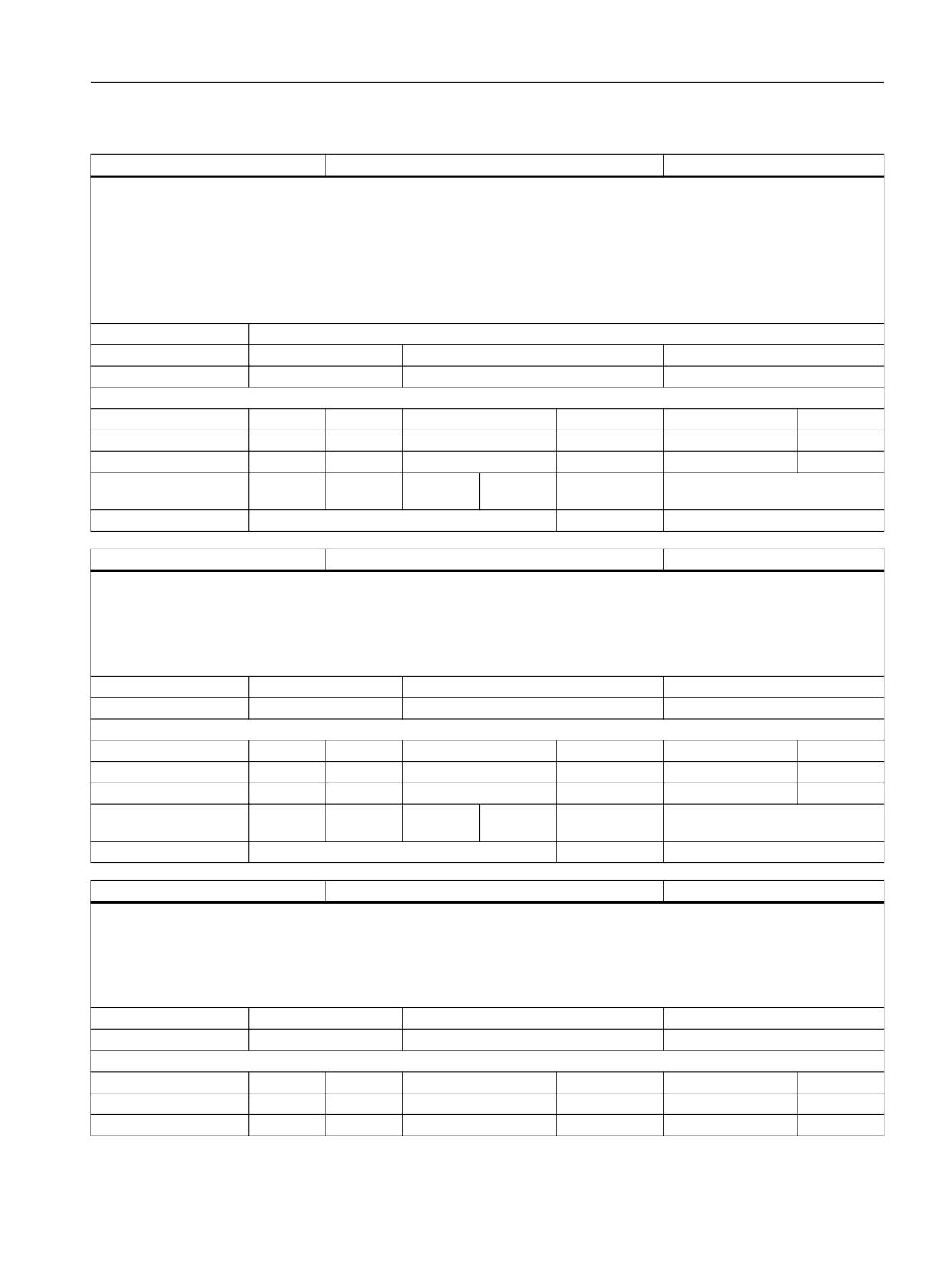
$P_ISO2_HNO [n]
H number in ISO2 mode
INT
Description:
Contains the offset numbers of H selected for the 3 geometry dimensions.
(Tool length offset) Indexing corresponding to
$P_TOOLL[n].
Value = -1: H99 is programmed, or it has been activated in Siemens mode D1.
= -2: A D>2 has been programmed in Siemens mode
= -3: It cannot be activated in ISO2 mode.
Index 1:
Geometry index of the tool length compensation
Unit
Init value
Min
Max
-
0
-3
2147483647
Read/Write properties:
TP
SA
TP/SA safety
NC-Variable
Safety
OEM-CC
Read:
X
-
7
X
7
-
Write:
-
-
0
-
0
-
Axis entry:
Overlap chan-
channel-specific
nel:
Scan mode:
Not classified
Link:
No restrictions
$P_ISO2_DNO
D number in ISO2 mode
INT
Description:
Contains the offset number D selected for the radius
Value = -1: H99 is programmed, or it has been activated in Siemens mode D1.
= -2: A D>2 has been programmed in Siemens mode
= -3: It cannot be activated in ISO2 mode.
Unit
Init value
Min
Max
-
0
-3
2147483647
Read/Write properties:
TP
SA
TP/SA safety
NC-Variable
Safety
OEM-CC
Read:
X
-
7
X
7
-
Write:
-
-
0
-
0
-
Axis entry:
Overlap chan-
channel-specific
nel:
Scan mode:
Not classified
Link:
No restrictions
$P_ISO3_DNO
D number in ISO3 mode
INT
Description:
Contains the offset number of H selected for ISO3 mode
Value = -1: H99 is programmed, or it has been activated in Siemens mode D1.
= -2: A D>2 has been programmed in Siemens mode
= -3: It cannot be activated in ISO2 mode.
Unit
Init value
Min
Max
-
0
-3
2147483647
Read/Write properties:
TP
SA
TP/SA safety
NC-Variable
Safety
OEM-CC
Read:
X
-
7
X
7
-
Write:
-
-
0
-
0
-
System variables
List Manual, 10/2020, 6FC5397-6AP40-6BA4
197
List of system variables
3.2 Channel-specific system variables
$P_ISO3_DNO
D number in ISO3 mode
INT
Axis entry:
Overlap chan-
channel-specific
nel:
Scan mode:
Not classified
Link:
No restrictions
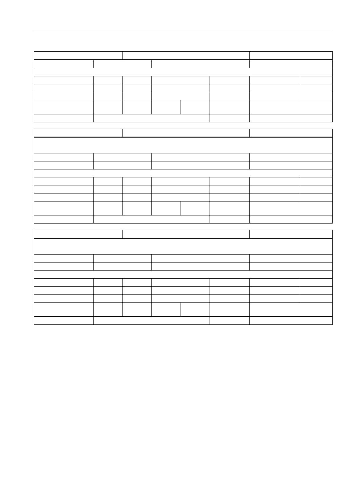
$AC_PREP_ACT_LOAD
Current preprocessing runtime
DOUBLE
Description:
The variable $AC_PREP_ACT_LOAD returns the current preprocessing runtime in the channel.
Unit
Init value
Min
Max
-
0.0
-1.8E+308
1.8E+308
Read/Write properties:
TP
SA
TP/SA safety
NC-Variable
Safety
OEM-CC
Read:
X
X
7
X
7
-
Write:
-
-
0
-
0
-
Axis entry:
Overlap chan-
channel-specific
nel:
Scan mode:
Not classified
Link:
Not classified
$AC_PREP_MAX_LOAD
Longest preprocessing runtime
DOUBLE
Description:
The variable $AC_PREP_MAX_LOAD returns the longest net preprocessing runtime in the channel.
Unit
Init value
Min
Max
-
0.0
-1.8E+308
1.8E+308
Read/Write properties:
TP
SA
TP/SA safety
NC-Variable
Safety
OEM-CC
Read:
X
X
7
X
7
-
Write:
X
X
7
-
0
-
Axis entry:
Overlap chan-
channel-specific
nel:
Scan mode:
Not classified
Link:
Not classified
$AC_PREP_MIN_LOAD
Shortest preprocessing runtime
DOUBLE
Description:
The variable $AC_PREP_MIN_LOAD returns the shortest net preprocessing runtime in the channel.
Unit
Init value
Min
Max
-
0.0
-1.8E+308
1.8E+308
Read/Write properties:
TP
SA
TP/SA safety
NC-Variable
Safety
OEM-CC
Read:
X
X
7
X
7
-
Write:
X
X
7
-
0
-
Axis entry:
Overlap chan-
channel-specific
nel:
Scan mode:
Not classified
Link:
Not classified
$AC_PREP_ACT_LOAD_GROSS
Current preprocessing runtime
DOUBLE
Description:
The variable $AC_PREP_ACT_LOAD_GROSS returns the current gross preprocessing runtime in the channel.
Unit
Init value
Min
Max
System variables
198
List Manual, 10/2020, 6FC5397-6AP40-6BA4
List of system variables
3.2 Channel-specific system variables
$AC_PREP_ACT_LOAD_GROSS
Current preprocessing runtime
DOUBLE
-
0.0
-1.8E+308
1.8E+308
Read/Write properties:
TP
SA
TP/SA safety
NC-Variable
Safety
OEM-CC
Read:
X
X
7
X
7
-
Write:
-
-
0
-
0
-
Axis entry:
Overlap chan-
channel-specific
nel:
Scan mode:
Not classified
Link:
Not classified
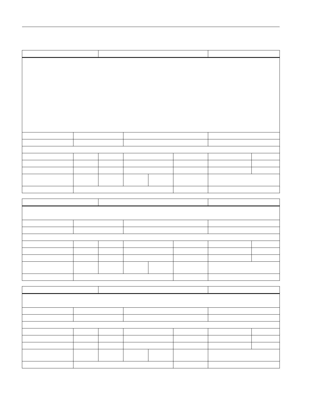
$AC_PREP_MAX_LOAD_GROSS
Longest preprocessing runtime
DOUBLE
Description:
The variable $AC_PREP_MAX_LOAD_GROSS returns the longest gross preprocessing runtime in the channel.
Unit
Init value
Min
Max
-
0.0
-1.8E+308
1.8E+308
Read/Write properties:
TP
SA
TP/SA safety
NC-Variable
Safety
OEM-CC
Read:
X
X
7
X
7
-
Write:
X
X
7
-
0
-
Axis entry:
Overlap chan-
channel-specific
nel:
Scan mode:
Not classified
Link:
Not classified
$AC_PREP_MIN_LOAD_GROSS
Shortest preprocessing runtime
DOUBLE
Description:
The variable $AC_PREP_MIN_LOAD_GROSS returns the shortest, gross preprocessing runtime in the channel.
Unit
Init value
Min
Max
-
0.0
-1.8E+308
1.8E+308
Read/Write properties:
TP
SA
TP/SA safety
NC-Variable
Safety
OEM-CC
Read:
X
X
7
X
7
-
Write:
X
X
7
-
0
-
Axis entry:
Overlap chan-
channel-specific
nel:
Scan mode:
Not classified
Link:
Not classified
System variables
List Manual, 10/2020, 6FC5397-6AP40-6BA4
199
List of system variables
3.2 Channel-specific system variables
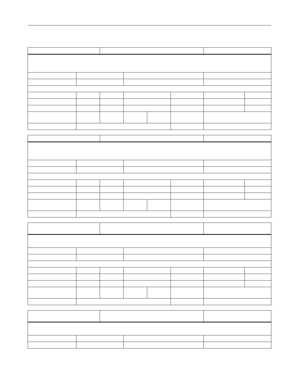
$AC_IPO_STATE
Status identifier of active functions
INT
Description:
$AC_IPO_STATE
The variable returns selected information about whether specific
functions are active:
Bit 0: Free-form surfaces mode is active
Bit 1: Compressor active
Bit 2: Vector interpolation (e.g. large circle interpolation) is active for tool orientation
Bit 3: Reserved for smoothing
Note:
This variable can only be read in synchronized actions, and not
directly in the part program.
Unit
Init value
Min
Max
-
0
-2147483648
2147483647
Read/Write properties:
TP
SA
TP/SA safety
NC-Variable
Safety
OEM-CC
Read:
-
X
0
X
7
X
Write:
-
-
0
-
0
-
Axis entry:
Overlap chan-
Cross-channel
nel:
Scan mode:
Not classified
Link:
Not classified
$AC_CTOL
Active contour tolerance
DOUBLE
Description:
$AC_CTOL defines the contour tolerance for compressors and smoothing with which the current main run block was prepared.
Unit
Init value
Min
Max
mm
0.0
-1.8E+308
1.8E+308
Read/Write properties:
TP
SA
TP/SA safety
NC-Variable
Safety
OEM-CC
Read:
runin stp
X
7
X
7
X
Write:
-
-
0
-
0
-
Axis entry:
Overlap chan-
channel-specific
nel:
Scan mode:
Not classified
Link:
Not classified
$AC_OTOL
Active orientation tolerance
DOUBLE
Description:
$AC_OTOL defines the orientation tolerance for compressors and smoothing with which the current main run block was prepared.
Unit
Init value
Min
Max
deg.
0.0
-1.8E+308
1.8E+308
Read/Write properties:
TP
SA
TP/SA safety
NC-Variable
Safety
OEM-CC
Read:
runin stp
X
7
X
7
X
Write:
-
-
0
-
0
-
Axis entry:
Overlap chan-
channel-specific
nel:
Scan mode:
Not classified
Link:
Not classified
System variables
200
List Manual, 10/2020, 6FC5397-6AP40-6BA4
List of system variables
3.2 Channel-specific system variables
$P_CTOL
Programmed contour tolerance
DOUBLE
Description:
$P_CTOL states the contour tolerance for compressors and smoothing programmed with CTOL in the part program. If no value is programmed,
the variable returns -1.
Unit
Init value
Min
Max
mm
0.0
-1.0
1.8E+308
Read/Write properties:
TP
SA
TP/SA safety
NC-Variable
Safety
OEM-CC
Read:
X
-
7
-
0
-
Write:
-
-
0
-
0
-
Axis entry:
Overlap chan-
channel-specific
nel:
Scan mode:
Not classified
Link:
Not classified
$P_OTOL
Programmed orientation tolerance
DOUBLE
Description:
$P_OTOL states the orientation tolerance for compressors and smoothing programmed with OTOL in the part program. If no value is pro-
grammed, the variable returns -1.
Unit
Init value
Min
Max
deg.
0.0
-1.0
1.8E+308
Read/Write properties:
TP
SA
TP/SA safety
NC-Variable
Safety
OEM-CC
Read:
X
-
7
-
0
-
Write:
-
-
0
-
0
-
Axis entry:
Overlap chan-
channel-specific
nel:
Scan mode:
Not classified
Link:
Not classified
$AC_FGROUP_MASK
Bit-coded value of axes that contribute to the path ve-
INT
locity
Description:
The variable returns a bit-coded value of channel axes programmed with the FGROUP command that contribute to the path velocity.
Unit
Init value
Min
Max
-
0
0
0xFFFF
Read/Write properties:
TP
SA
TP/SA safety
NC-Variable
Safety
OEM-CC
Read:
runin stp
X
7
X
7
X
Write:
-
-
0
-
0
-
Axis entry:
Overlap chan-
channel-specific
nel:
Scan mode:
Not classified
Link:
Not classified
$P_FGROUP_MASK
Bit-coded mask of axes that contribute to the path ve-
INT
locity
Description:
The variable returns a bit-coded value from programmed channel axes that contribute to the path velocity via the FGROUP command.
Unit
Init value
Min
Max
-
0
0
0xFFFF
System variables
List Manual, 10/2020, 6FC5397-6AP40-6BA4
201
List of system variables
3.2 Channel-specific system variables
$P_FGROUP_MASK
Bit-coded mask of axes that contribute to the path ve-
INT
locity
Read/Write properties:
TP
SA
TP/SA safety
NC-Variable
Safety
OEM-CC
Read:
X
-
7
-
0
-
Write:
-
-
0
-
0
-
Axis entry:
Overlap chan-
channel-specific
nel:
Scan mode:
Not classified
Link:
Not classified
$AC_AUXFU_EXT [168]
Extension of the active auxiliary function
INT
Description:
The array variable $AC_AUXFU_EXT[n] is used to read the extension of the last auxiliary function collected for an auxiliary function group
(search run) or output. Auxiliary functions are assigned to groups. The index corresponds to the group number decremented by one. The index
0 thus determines the extension of the last output auxiliary function of the 1st group. If an auxiliary function has not yet been output for the
specified group, then the variable returns the value -1. The associated value of the auxiliary function can be determined by the variable
$AC_AUXFU_VALUE[n]. The variable $AC_AUXFU_STATE[n] determines the current output status.
Index 1:
The index corresponds to the auxiliary function group number decremented by one.
Unit
Init value
Min
Max
-
0
-2147483648
2147483647
Read/Write properties:
TP
SA
TP/SA safety
NC-Variable
Safety
OEM-CC
Read:
runin stp
X
7
X
7
X
Write:
-
-
0
-
0
-
Axis entry:
Overlap chan-
channel-specific
nel:
Scan mode:
Not classified
Link:
Not classified
$AC_AUXFU_STATE [168]
Output status of the active auxiliary function
INT
Description:
The array variable $AC_AUXFU_STATE[n] is used to read the output status of the last auxiliary function collected for an auxiliary function group
(search run) or output. Auxiliary functions are assigned to groups. The index corresponds to the group number decremented by one. The index
0 thus determines the status of the last output auxiliary function of the 1st group. If an auxiliary function has not yet been output for the
specifed group, then the variable returns the value 0. If the value is greater than zero, then the value of the associated auxiliary function can
be determined by the variable $AC_AUXFU_VALUE[n]. The variable $AC_AUXFU_EXT[n] determines the current extension of the auxiliary
function.
The variable returns the following values
0: Auxiliary function not available
1: Auxiliary function has been collected by means of a search run
2: Auxiliary function has been output to the PLC
3: Auxiliary function has been output to the PLC and the transport acknowledgement has been made.
4: Auxiliary function has been accepted is being managed by the PLC.
5: Auxiliary function is being managed by the PLC and the function acknowledgement has been made.
Index 1:
The index corresponds to the auxiliary function group number decremented by one.
Unit
Init value
Min
Max
-
0
0
5
Read/Write properties:
TP
SA
TP/SA safety
NC-Variable
Safety
OEM-CC
Read:
runin stp
X
7
X
7
X
Write:
-
-
0
-
0
-
System variables
202
List Manual, 10/2020, 6FC5397-6AP40-6BA4
List of system variables
3.2 Channel-specific system variables
$AC_AUXFU_STATE [168]
Output status of the active auxiliary function
INT
Axis entry:
Overlap chan-
channel-specific
nel:
Scan mode:
Not classified
Link:
Not classified
$AC_AUXFU_VALUE [168]
Value of the active auxiliary function
DOUBLE
Description:
The array variable $AC_AUXFU_VALUE[n] is used to read the value of the last auxiliary function collected for an auxiliary function group (search
run) or output. Auxiliary functions are assigned to groups. The index corresponds to the group number decremented by one. The index 0 thus
determines the value of the last output auxiliary function of the 1st group. If an auxiliary function has not yet been output for the specified
group, then the variable returns the value -1. The associated extension can be determined by the variable $AC_AUXFU_EXT[n]. The variable
$AC_AUXFU_STATE[n] determines the current output status.
Index 1:
The index corresponds to the auxiliary function group number decremented by one.
Unit
Init value
Min
Max
-
0.0
-2147483648
2147483647
Read/Write properties:
TP
SA
TP/SA safety
NC-Variable
Safety
OEM-CC
Read:
runin stp
X
7
X
7
X
Write:
-
-
0
-
0
-
Axis entry:
Overlap chan-
channel-specific
nel:
Scan mode:
Not classified
Link:
Not classified
$AC_AUXFU_TICK [168,2]
Output counter of the active auxiliary function
INT
Description:
The array variable $AC_AUXFU_TICK[groupIndex, n] is used to read the three output counters of the last auxiliary function collected for an
auxiliary function group (search run) or output.
The variable is changed each time an auxiliary function is changed.
n = 0: Output sequence counter (all outputs within one IPO cycle)
n = 1: Package counter within an output sequence in the interpolation cycle
n = 2: Auxiliary function counter within a package
An auxiliary function package consists of a maximum of 10 auxiliary functions. Two packages per channel can be executed in each IPO cycle
during SERUPRO. An output sequence of up to 20 packages can be executed through all channels in one IPO cycle.
All the auxiliary functions collected in one IPO cycle have the same sequence counter.
All the auxiliary functions collected in one package (block or synact) have the same package counter.
The auxiliary function counter is incremented for each auxiliary function collected.
Index 1:
The index corresponds to the auxiliary function group number decremented by one.
Index 2:
The index corresponds to the counter type
Unit
Init value
Min
Max
-
0
-2147483648
2147483647
Read/Write properties:
TP
SA
TP/SA safety
NC-Variable
Safety
OEM-CC
Read:
runin stp
X
7
X
7
X
Write:
-
-
0
-
0
-
Axis entry:
Overlap chan-
channel-specific
nel:
Scan mode:
Not classified
Link:
Not classified
System variables
List Manual, 10/2020, 6FC5397-6AP40-6BA4
203
List of system variables
3.2 Channel-specific system variables
$AC_AUXFU_TYPE [168]
Types of active auxiliary function
CHAR
Description:
The array variable $AC_AUXFU_TYPE[n] is used to read the types M, H, S, T, D, F, L of the last auxiliary function collected for an auxiliary function
group (search run) or output. Auxiliary functions are assigned to groups. The index corresponds to the group number decremented by one. The
index 0 thus determines the types of the last output auxiliary function of the 1st group. If an auxiliary function has not yet been output for the
specifed group, then the variable returns the value "". The associated value of the auxiliary function can be determined by the variable
$AC_AUXFU_VALUE[n]. The variable $AC_AUXFU_STATE[n] determines the current output status.
Index 1:
The index corresponds to the auxiliary function group number decremented by one.
Unit
Init value
Min
Max
-
0
0
CHAR_MAX
Read/Write properties:
TP
SA
TP/SA safety
NC-Variable
Safety
OEM-CC
Read:
runin stp
X
7
X
7
X
Write:
-
-
0
-
0
-
Axis entry:
Overlap chan-
channel-specific
nel:
Scan mode:
Not classified
Link:
Not classified
$AC_AUXFU_PREDEF_INDEX [168]
Predefined index of the active auxiliary function
INT
Description:
The array variable $AC_AUXFU_PREDEF_INDEX[n] is used to read the predefined index of the last auxiliary function collected for an auxiliary
function group (search run) or output. Auxiliary functions are assigned to groups. The array index corresponds to the group number decre-
mented by one. The index 0 thus determines the predefined index of the last output auxiliary function of the 1st group. If an auxiliary function
has not yet been output for the specifed group or if the auxiliary function is a user-defined auxiliary function, then the variable returns the value
-1. The associated value of the auxiliary function can be determined by the variable $AC_AUXFU_VALUE[n]. The variable $AC_AUXFU_STATE[n]
determines the current output status.
Index 1:
The index corresponds to the auxiliary function group number decremented by one.
Unit
Init value
Min
Max
-
0
-1
2147483647
Read/Write properties:
TP
SA
TP/SA safety
NC-Variable
Safety
OEM-CC
Read:
runin stp
X
7
X
7
X
Write:
-
-
0
-
0
-
Axis entry:
Overlap chan-
channel-specific
nel:
Scan mode:
Not classified
Link:
Not classified
System variables
204
List Manual, 10/2020, 6FC5397-6AP40-6BA4
List of system variables
3.2 Channel-specific system variables
$AC_AUXFU_SPEC [168]
Output specification of the active auxiliary function
INT
Description:
The array variable $AC_AUXFU_SPEC[n] is used to read the output specification corresponding to $MC_AUXFU_PREDEF_SPEC[n], $MC_AUX-
FU_ASSIGN_SPEC[n] of the last auxiliary function collected for an auxiliary function group (search run) or output. Auxiliary functions are
assigned to groups. The index corresponds to the group number decremented by one. The index 0 thus determines the specification of the last
output auxiliary function of the 1st group. The associated value of the auxiliary function can be determined by the variable $AC_AUXFU_VAL-
UE[n]. The variable $AC_AUXFU_STATE[n] determines the current output status.
The output specification is bit-coded:
Bit 0 = 1 acknowledgment "normal" after an OB1 cycle
Bit 1 = 1 acknowledgment "quick" with OB40
Bit 2 = 1 No predefined auxiliary function
Bit 3 = 1 No output to the PLC
Bit 4 = 1 Spindle reaction after acknowledgement by the PLC
Bit 5 = 1 Output before the motion
Bit 6 = 1 Output during the motion
Bit 7 = 1 Output at end of block
Bit 8 = 1 No output after block search types 1, 2, 4
Bit 9 = 1 Collection during block search type 5 (SERUPRO)
Bit10 = 1 No output during block search type 5 (SERUPRO)
Bit 11 = 1 Cross-channel auxiliary function (SERUPRO)
Bit 12 = 1 Output via synchronized action
Bit 13 = 1 Implicit auxiliary function
Bit 14 = 1 Active M01
Bit 15 = 1 No output during running-in test
Bit 16 = 1 Nibbling off
Bit 17 = 1 Nibbling on
Bit 18 = 1 Nibbling
Index 1:
The index corresponds to the auxiliary function group number decremented by one.
Unit
Init value
Min
Max
-
0
-2147483648
2147483647
Read/Write properties:
TP
SA
TP/SA safety
NC-Variable
Safety
OEM-CC
Read:
runin stp
X
7
X
7
X
Write:
-
-
0
-
0
-
Axis entry:
Overlap chan-
channel-specific
nel:
Scan mode:
Not classified
Link:
Not classified
$P_TRAFRAME_P
Frame of the workpiece component of an active orien-
FRAME
tation transformation
Description:
This variable returns the frame, which describes the current rotation and offset of the workpiece part of an active kinematic orientation
transformation.
Here, workpiece part means the kinematic chain defined between machine zero and workpiece reference point.
Unit
Init value
Min
Max
-
Read/Write properties:
TP
SA
TP/SA safety
NC-Variable
Safety
OEM-CC
System variables
List Manual, 10/2020, 6FC5397-6AP40-6BA4
205
List of system variables
3.2 Channel-specific system variables
$P_TRAFRAME_P
Frame of the workpiece component of an active orien-
FRAME
tation transformation
Read:
X
-
7
-
0
-
Write:
-
-
0
-
0
-
Axis entry:
GEO
CHAN
MACH
SPIN
Overlap chan-
channel-specific
nel:
Scan mode:
Not classified
Link:
No restrictions
$P_TRAFRAME_T
Frame of the workpiece component of an active orien-
FRAME
tation transformation
Description:
This variable returns the frame, which describes the current rotation and offset of the tool part of an active kinematic orientation transfor-
mation.
Here, tool part means the kinematic chain defined between machine zero and tool reference point.
Unit
Init value
Min
Max
-
Read/Write properties:
TP
SA
TP/SA safety
NC-Variable
Safety
OEM-CC
Read:
X
-
7
-
0
-
Write:
-
-
0
-
0
-
Axis entry:
GEO
CHAN
MACH
SPIN
Overlap chan-
channel-specific
nel:
Scan mode:
Not classified
Link:
No restrictions
$P_FZ
Programmed tooth feed
DOUBLE
Description:
The variable $P_FZ is used to read the last programmed tooth feed FZ.
Unit
Init value
Min
Max
mm/min
0
2.2E-308
1.8E+308
Read/Write properties:
TP
SA
TP/SA safety
NC-Variable
Safety
OEM-CC
Read:
X
-
7
-
0
-
Write:
-
-
0
-
0
-
Axis entry:
Overlap chan-
channel-specific
nel:
Scan mode:
Not classified
Link:
Not classified
$AC_FZ
Active programmed tooth feed
DOUBLE
Description:
The variable $AC_FZ is used to read the active programmed tooth feed FZ.
Unit
Init value
Min
Max
mm/min
0
2.2E-308
1.8E+308
Read/Write properties:
TP
SA
TP/SA safety
NC-Variable
Safety
OEM-CC
Read:
runin stp
X
7
X
7
-
Write:
-
-
0
-
0
-
Axis entry:
Overlap chan-
channel-specific
nel:
Scan mode:
Not classified
Link:
Not classified
System variables
206
List Manual, 10/2020, 6FC5397-6AP40-6BA4
List of system variables
3.2 Channel-specific system variables
$P_F_TYPE
Types of programmed feed
INT
Description:
The variable $P_F_TYPE is used to read the type of the last programmed feed.
Unit
Init value
Min
Max
-
0
ICFEED_METRIC_TIME
ICFEED_INCH_TEETH
Read/Write properties:
TP
SA
TP/SA safety
NC-Variable
Safety
OEM-CC
Read:
X
-
7
-
0
-
Write:
-
-
0
-
0
-
Axis entry:
Overlap chan-
channel-specific
nel:
Scan mode:
Not classified
Link:
Not classified
$AC_F_TYPE
Types of active programmed feed
INT
Description:
The variable $AC_F_TYPE is used to read the type of the active programmed feed.
Unit
Init value
Min
Max
-
0
0
31
Read/Write properties:
TP
SA
TP/SA safety
NC-Variable
Safety
OEM-CC
Read:
runin stp
X
7
X
7
-
Write:
-
-
0
-
0
-
Axis entry:
Overlap chan-
channel-specific
nel:
Scan mode:
Not classified
Link:
Not classified
$P_SVC [1]
Programmed cutting speed
DOUBLE
Description:
The variable $P_SVC[n] is used to read the last programmed cutting speed SVC.
n: Number of the spindle
Index 1:
n: Spindle number (0 ... max. spindle number)
Unit
Init value
Min
Max
mm/min
0
2.2E-308
1.8E+308
Read/Write properties:
TP
SA
TP/SA safety
NC-Variable
Safety
OEM-CC
Read:
X
-
7
-
0
-
Write:
-
-
0
-
0
-
Axis entry:
Overlap chan-
channel-specific
nel:
Scan mode:
Not classified
Link:
Not classified
$AC_SVC [1]
Active programmed cutting speed
DOUBLE
Description:
The variable $AC_SVC is used to read the active programmed cutting speed SVC.
n: Number of the spindle
Index 1:
n: Spindle number (0 ... max. spindle number)
Unit
Init value
Min
Max
System variables
List Manual, 10/2020, 6FC5397-6AP40-6BA4
207
List of system variables
3.2 Channel-specific system variables
$AC_SVC [1]
Active programmed cutting speed
DOUBLE
mm/min
0
2.2E-308
1.8E+308
Read/Write properties:
TP
SA
TP/SA safety
NC-Variable
Safety
OEM-CC
Read:
runin stp
X
7
X
7
-
Write:
-
-
0
-
0
-
Axis entry:
Overlap chan-
channel-specific
nel:
Scan mode:
Not classified
Link:
Not classified
$P_S_TYPE [1]
Type of spindle programming
INT
Description:
The variable $P_S_TYPE is used to read the type of spindle programming.
0 Spindle not programmed
1 Spindle speed S in rpm
2 Cutting speed SVC in m/min or ft/min
3 Constant cutting speed S in m/min or ft/min
4 Constant grinding wheel peripheral speed S in m/s or ft/s
Index 1:
n: Spindle number (0 ... max. spindle number)
Unit
Init value
Min
Max
-
0
0
31
Read/Write properties:
TP
SA
TP/SA safety
NC-Variable
Safety
OEM-CC
Read:
X
-
7
-
0
-
Write:
-
-
0
-
0
-
Axis entry:
Overlap chan-
channel-specific
nel:
Scan mode:
Not classified
Link:
Not classified
$AC_S_TYPE [1]
Types of active spindle programming
INT
Description:
The variable $P_S_TYPE is used to read the active type of spindle programming.
0 Spindle not programmed
1 Spindle speed S in rpm
2 Cutting speed SVC in m/min or ft/min
3 Constant cutting speed S in m/min or ft/min
4 Constant grinding wheel peripheral speed S in m/s or ft/s
Index 1:
n: Spindle number (0 ... max. spindle number)
Unit
Init value
Min
Max
-
0
0
31
Read/Write properties:
TP
SA
TP/SA safety
NC-Variable
Safety
OEM-CC
Read:
runin stp
X
7
X
7
-
Write:
-
-
0
-
0
-
Axis entry:
Overlap chan-
channel-specific
nel:
Scan mode:
Not classified
Link:
Not classified
System variables
208
List Manual, 10/2020, 6FC5397-6AP40-6BA4
List of system variables
3.2 Channel-specific system variables
$VC_SGEAR [n]
Currently activated spindle gear stage
INT
Description:
The variable $VC_SGEAR[spino] determines the currently activated spindle gear stage. $AC_SGEAR[spino] determines the set gear stage in the
main run. In the case of the search run, the actual gear stage can vary from the set gear stage, as a gear stage change cannot take place during
the search run. Using $VC_SGEAR[spino] and $AC_SGEAR[spino], it can be checked whether a gear stage change should take place following
a search run.
The following values are possible:
1: 1. Gear stage is active
5: 5. Gear stage is active
Index 1:
0 ... max. spindle number
Unit
Init value
Min
Max
-
0
1
5
Read/Write properties:
TP
SA
TP/SA safety
NC-Variable
Safety
OEM-CC
Read:
runin stp
X
7
X
7
X
Write:
-
-
0
-
0
-
Axis entry:
Overlap chan-
channel-specific
nel:
Scan mode:
Not classified
Link:
Not classified
$P_ORI_POS [2,3]
Positions of the orientation axes in the case of orienta-
DOUBLE
tion programming
Description:
The angles of the orientation axes, which result from orientation programming.
In this case, the first index (0 or 1) refers to the solution, whereas the second index (0..2) refers to the orientation axis, see also $P_ORI_SOL
and $P_ORI_STAT.
When the function ORISOLH is called in the mode "Direct tool alignment", the variables $P_ORI_POS[0 /1, 1] and P_ORI_POS[0 /1, 2] contain
the values of the two angles BETA und GAMMA belonging to both solutions.
Index 1:
Index of the solution
Index 2:
Index of the orientation axis
Unit
Init value
Min
Max
-
0.0
2.2E-308
1.8E+308
Read/Write properties:
TP
SA
TP/SA safety
NC-Variable
Safety
OEM-CC
Read:
X
-
7
-
0
-
Write:
-
-
0
-
0
-
Axis entry:
Overlap chan-
channel-specific
nel:
Scan mode:
Not classified
Link:
No restrictions
System variables
List Manual, 10/2020, 6FC5397-6AP40-6BA4
209
List of system variables
3.2 Channel-specific system variables
$P_ORI_DIFF [2,3]
Deviation of axis positions from theor. value in the case
DOUBLE
of orientation progr.
Description:
The difference between the exact positions of the orientation axes and those provided in $P_ORI_POS, which result from orientation pro-
gramming.
The content may be unequal to zero only if the positions are gridded (Hirth tooth system), i.e if the system data $NT_HIRTH_INCR of the
affected axis is unequal to zero and if this axis is a manual rotary axis.
In this case, the first index (0 or 1) refers to the solution, whereas the second index (0..2) refers to the orientation axis, see also $P_ORI_SOL.
Index 1:
Index of the solution
Index 2:
Index of the orientation axis
Unit
Init value
Min
Max
-
0.0
2.2E-308
1.8E+308
Read/Write properties:
TP
SA
TP/SA safety
NC-Variable
Safety
OEM-CC
Read:
X
-
7
-
0
-
Write:
-
-
0
-
0
-
Axis entry:
Overlap chan-
channel-specific
nel:
Scan mode:
Not classified
Link:
No restrictions
System variables
210
List Manual, 10/2020, 6FC5397-6AP40-6BA4
List of system variables
3.2 Channel-specific system variables
$P_ORI_SOL
Number of solutions in the case of orientation program-
INT
ming
Description:
If the axis positions are calculated for an orientation transformation with more than one orientation axis which should result in a specified
orientation, there is generally more than one solution.
This system data contains the number of valid solutions together with additional status information.
The content of $P_ORI_SOL is coded as follows:
Negative values: General error states.
-1: No solutions have been calculated for the active transformation (missing call of ORISOL).
-2: No transformation is active or the active transformation is not an orientation transformation, which is able to return positions for a
specified orientation programming.
-5: On calling ORISOLH for "Swivel direct", no solution was found.
-6: On calling ORISOLH for "Swivel direct", the angle GAMMA was too large.
-7: On calling ORISOLH for "Swivel direct", an angle was specified that could not be set because of the Hirth tooth system.
Units digit: Number of mathematically possible solutions without considering axis limits and possible error conditions.
0: A solution does not exist, i.e. the required orientation cannot be set.
1: One solution exists.
2: Two solutions exist.
9: An infinite number of solutions exist, i.e. the position of at least one orientation axis is not specified. The unspecified axis can be determined
from the hundreds digit or from the system variable $P_ORI_STAT.
Tens digit: Bit-coded display for violated axis limits. The exact cause of the error can be determined from the system variable $P_ORI_STAT.
Bit 0 (value 10): At least one axis limit of the 1st orientation axis is violated for at least one solution.
Bit 1 (value 20): At least one axis limit of the 2nd orientation axis is violated for at least one solution.
Bit 2 (value 40): At least one axis limit of the 3rd orientation axis is violated for at least one solution.
Hundreds digit: Bit-coded display for non-defined axis positions (can only occur if there are an infinite number of solutions, i.e. if the units digit
is equal to 9).
Bit 0 (value 100): The position of the 1st orientation axis is not defined.
Bit 1 (value 200): The position of the 2nd orientation axis is not defined.
Bit 2 (value 400): The position of the 3rd orientation axis is not defined.
The identifiers 1st, 2nd and 3rd orientation axis refer to the definition of the axes in the transformation data $NT_ROT_AX_NAME.
Unit
Init value
Min
Max
-
0
-2147483648
2147483647
Read/Write properties:
TP
SA
TP/SA safety
NC-Variable
Safety
OEM-CC
Read:
X
-
7
-
0
-
Write:
-
-
0
-
0
-
Axis entry:
Overlap chan-
channel-specific
nel:
Scan mode:
Not classified
Link:
No restrictions
System variables
List Manual, 10/2020, 6FC5397-6AP40-6BA4
211
List of system variables
3.2 Channel-specific system variables
$P_ORI_STAT [ORIDIM]
Status of the orientation axes
INT
Description:
The system variable contains the status of each orientation axis following the call of ORISOL.
The index n of $P_ORI_STAT[n] corresponds to the index of the affected orientation axis in the transformation data $NT_ROT_AX_NAME[n].
The content of $P_ORI_SOL is coded as follows:
Negative values: General error states.
-1: The status is not defined (missing call of ORISOL).
-2: No transformation is active or the active transformation is not an orientation transformation, which is able to return positions for a
specified orientation programming.
-3: The axis is not contained in the active transformation.
-4: The position of the axis cannot be calculated, because the desired orientation cannot be achieved with the specified kinematics, even with
any assumed traversing range of the axis.
-5: On calling the function ORISOLH for "Swivel direct", axis positions were specified in such a way that either the orientation vector or the
orientation normal vector of the tool was aligned parallel to the first orientation axis, the position of which is to be calculated. In these cases,
the position of this axis is not defined.
-6: On calling ORISOLH for "Swivel direct", the angle GAMMA was too large.
-7: On calling ORISOLH for "Swivel direct", an angle was specified that could not be set because of the Hirth tooth system.
-8: The first orientation axis must not be parameterized as a Hirth axis.
-9: Both the second and third rotary axes are parameterized as Hirth axes. A maximum of only one of the two axes may be a Hirth axis.
-10: No adaptation to the Hirth tooth system was found.
Units digit: Bit-coded display for violated axis limits of the first solution.
Bit 0 (value 1): The first solution violates the lower axis limit.
Bit 1 (value 2): The first solution violates the upper axis limit.
Tens digit: Bit-coded display for violated axis limits of the second solution.
Bit 0 (value 10): The second solution violates the lower axis limit.
Bit 1 (value 20): The second solution violates the upper axis limit.
Hundreds digit: Displays a non-defined axis position.
Bit 0 (value 100): The position of the orientation axis is not defined, i.e. the required orientation is achieved through any setting of the rotary
axis (pole setting). This information is also contained the system variable $P_ORI_SOL.
Several fault codes, which display violation of the axis limits, can occur simultaneously. As, in the case of violation of an axis limit, an attempt
is made to achieve a position within the permitted axis limits by adding or subtracting multiples of 360 degrees, if this is not possible - it is not
clearly defined, whether the lower or upper axis limit was violated.
If a solution is not available for the desired orientation ($P_ORI_SOL equals 0), the status of the orientation axes contained in the transformation
is 0.
Index 1:
--
Unit
Init value
Min
Max
-
0
-2147483648
2147483647
Read/Write properties:
TP
SA
TP/SA safety
NC-Variable
Safety
OEM-CC
Read:
X
-
7
-
0
-
Write:
-
-
0
-
0
-
Axis entry:
Overlap chan-
channel-specific
nel:
Scan mode:
Not classified
Link:
No restrictions
System variables
212
List Manual, 10/2020, 6FC5397-6AP40-6BA4
List of system variables
3.2 Channel-specific system variables
$P_MTOOLN
Number of defined Multitools
INT
Description:
$P_MTOOLN
Number of defined Multitools, which are assigned to the channel
OPI block type= MTV
Unit
Init value
Min
Max
-
0
-2
1500
Read/Write properties:
TP
SA
TP/SA safety
NC-Variable
Safety
OEM-CC
Read:
X
-
7
X
7
-
Write:
-
-
0
-
0
-
Axis entry:
Overlap chan-
channel-specific
nel:
Scan mode:
Not classified
Link:
No restrictions
$P_MTOOLMT [1500]
Multitool number
INT
Description:
$P_MTOOLMT[i]
i-te Multitool number
OPI block type= MTV
Index 1:
i-th multitool, with i= 1,..., $P_MTOOLN
Unit
Init value
Min
Max
-
0
-2
1500
Read/Write properties:
TP
SA
TP/SA safety
NC-Variable
Safety
OEM-CC
Read:
X
-
7
X
7
-
Write:
-
-
0
-
0
-
Axis entry:
Overlap chan-
channel-specific
nel:
Scan mode:
Not classified
Link:
No restrictions
$P_MTOOLNT [32000]
Number of tools in Multitool
INT
Description:
$P_MTOOLNT
Number of tools in Multitool
Index 1:
Number of the multitool; 1,..., SLMAXTOOLNUMBER
Unit
Init value
Min
Max
-
0
-3
72
Read/Write properties:
TP
SA
TP/SA safety
NC-Variable
Safety
OEM-CC
Read:
X
-
7
-
0
-
Write:
-
-
0
-
0
-
Axis entry:
Overlap chan-
channel-specific
nel:
Scan mode:
Not classified
Link:
No restrictions
System variables
List Manual, 10/2020, 6FC5397-6AP40-6BA4
213
List of system variables
3.2 Channel-specific system variables
$P_MTOOLT [32000,72]
T number of the i-th tool in MT
INT
Description:
$P_MTOOLT
T number of the i-th tool in Multitool
Index 1:
Number of the multitool; 1,..., SLMAXTOOLNUMBER
Index 2:
i-th tool in the multitool, with i= 1,..., $P_MTOOLNT
Unit
Init value
Min
Max
-
0
-2
1500
Read/Write properties:
TP
SA
TP/SA safety
NC-Variable
Safety
OEM-CC
Read:
X
-
7
-
0
-
Write:
-
-
0
-
0
-
Axis entry:
Overlap chan-
channel-specific
nel:
Scan mode:
Not classified
Link:
No restrictions
$A_MYMTN [32000]
MT number of the proprietary multitool of a tool
INT
Description:
$A_MYMTN[t]
MT number of the proprietary multitool of the tool with the T no. t.
> 0 The tool with the T number t is a multitool with the MT number
= 0 The tool with the T number t is not a multitool
= -1 TMMG function inactive
= -2 Multitool function inactive
= -3 t is not WZ_T_Nr.
Index 1:
t: T number 1 - SLMAXTOOLNUMBER
Unit
Init value
Min
Max
-
0
-3
32000
Read/Write properties:
TP
SA
TP/SA safety
NC-Variable
Safety
OEM-CC
Read:
X
X
7
X
7
X
Write:
-
-
0
-
0
-
Axis entry:
Overlap chan-
channel-specific
nel:
Scan mode:
Not classified
Link:
No restrictions
$A_TOOLMTN [32000]
-
INT
Description:
$A_TOOLMTN[t]
Multitool number of tool t
Index 1:
t: T number 1 - SLMAXTOOLNUMBER
Unit
Init value
Min
Max
-
0
-3
32000
Read/Write properties:
TP
SA
TP/SA safety
NC-Variable
Safety
OEM-CC
Read:
X
X
7
X
7
X
Write:
-
-
0
-
0
-
System variables
214
List Manual, 10/2020, 6FC5397-6AP40-6BA4
List of system variables
3.2 Channel-specific system variables
$A_TOOLMTN [32000]
-
INT
Axis entry:
Overlap chan-
channel-specific
nel:
Scan mode:
Not classified
Link:
No restrictions
$A_MYMTLN [32000]
-
INT
Description:
$A_MYMTLN[t]
Number of the proprietary Multitool tool location with the T No. t.
Index 1:
t: T number 1 - SLMAXTOOLNUMBER
Unit
Init value
Min
Max
-
0
-3
32000
Read/Write properties:
TP
SA
TP/SA safety
NC-Variable
Safety
OEM-CC
Read:
X
X
7
X
7
X
Write:
-
-
0
-
0
-
Axis entry:
Overlap chan-
channel-specific
nel:
Scan mode:
Not classified
Link:
No restrictions
$A_TOOLMTLN [32000]
-
INT
Description:
$A_TOOLMTLN[t]
Multitool location number of tool t
Index 1:
t: T number 1 - SLMAXTOOLNUMBER
Unit
Init value
Min
Max
-
0
-3
32000
Read/Write properties:
TP
SA
TP/SA safety
NC-Variable
Safety
OEM-CC
Read:
X
X
7
X
7
X
Write:
-
-
0
-
0
-
Axis entry:
Overlap chan-
channel-specific
nel:
Scan mode:
Not classified
Link:
No restrictions
$AC_TC_TOOLIS
Is a simple tool or a Multitool transported?
INT
Description:
$AC_TC_TOOLIS
-1: At the time of reading, no tool command is active.
0: the transported tool is an individual tool.
1: the transported tool is an MT with a location number as distance coding.
2: the transported tool is an MT with length distance as distance coding.
3: the transported tool is an MT with angle distance as distance coding.
Unit
Init value
Min
Max
-
-1
-1
3
Read/Write properties:
TP
SA
TP/SA safety
NC-Variable
Safety
OEM-CC
Read:
runin stp
X
7
X
7
X
System variables
List Manual, 10/2020, 6FC5397-6AP40-6BA4
215
List of system variables
3.2 Channel-specific system variables
$AC_TC_TOOLIS
Is a simple tool or a Multitool transported?
INT
Write:
-
-
0
-
0
-
Axis entry:
Overlap chan-
channel-specific
nel:
Scan mode:
Not classified
Link:
Not classified
$AC_TC_MTDIST
Distance between tool in Multitool and the reference
DOUBLE
point
Description:
$AC_TC_MTDIST
Distance between tool in Multitool and the reference point.
-1.0: At the time of reading, no tool management command is active.
Unit
Init value
Min
Max
-
0
-1.0
1000.0
Read/Write properties:
TP
SA
TP/SA safety
NC-Variable
Safety
OEM-CC
Read:
runin stp
X
7
X
7
X
Write:
-
-
0
-
0
-
Axis entry:
Overlap chan-
channel-specific
nel:
Scan mode:
Not classified
Link:
Not classified
$AC_TC_MTNLOC
Number of locations for tool change and tool transport
INT
contained in the MT
Description:
$AC_TC_MTNLOC
Number of locations for tool change and tool transport contained in the MT.
-1: At the time of reading, no tool management command is active.
0: The new tool of the command at the PLC is a single tool.
>=2: The new tool of the command at the PLC is an MT with the specified number of locations.
Unit
Init value
Min
Max
-
-1
-1
72
Read/Write properties:
TP
SA
TP/SA safety
NC-Variable
Safety
OEM-CC
Read:
runin stp
X
7
X
7
X
Write:
-
-
0
-
0
-
Axis entry:
Overlap chan-
channel-specific
nel:
Scan mode:
Not classified
Link:
Not classified
$AC_TC_MTTN
Number of the Multitool with the new tool
INT
Description:
$AC_TC_MTTN
Number of the Multitool with the new tool
-1: At the time of reading, no tool management command is active.
0: The new tool of the command at the PLC is a single tool.
>0: The new tool of the command at the PLC is an MT with this number.
Unit
Init value
Min
Max
-
-1
-1
32000
System variables
216
List Manual, 10/2020, 6FC5397-6AP40-6BA4
List of system variables
3.2 Channel-specific system variables
$AC_TC_MTTN
Number of the Multitool with the new tool
INT
Read/Write properties:
TP
SA
TP/SA safety
NC-Variable
Safety
OEM-CC
Read:
runin stp
X
7
X
7
X
Write:
-
-
0
-
0
-
Axis entry:
Overlap chan-
channel-specific
nel:
Scan mode:
Not classified
Link:
Not classified
$AC_TC_MTLTN
Number of the Multitool location with the new tool
INT
Description:
$AC_TC_MTLTN
Number of the Multitool location with the new tool.
-1: At the time of reading, no tool management command is active.
0: The new tool of the command at the PLC is a single tool.
>0: MT location number of the target location of the new tool.
Unit
Init value
Min
Max
-
-1
-1
32000
Read/Write properties:
TP
SA
TP/SA safety
NC-Variable
Safety
OEM-CC
Read:
runin stp
X
7
X
7
X
Write:
-
-
0
-
0
-
Axis entry:
Overlap chan-
channel-specific
nel:
Scan mode:
Not classified
Link:
Not classified
$AC_PRTIME_B
Program runtime per block
DOUBLE
Description:
The variable $AC_PRTIME_B "ProgramRunTIME-Block" determines the program runtime per block.
During the simulation, the anticipated processing time of the blocks in the part program is calculated, and made available in this system variable
and the OPI variable 'acPRTimeB'.
Unit
Init value
Min
Max
-
0.0
0
1.8E+308
Read/Write properties:
TP
SA
TP/SA safety
NC-Variable
Safety
OEM-CC
Read:
runin stp
X
7
X
7
X
Write:
-
-
0
-
0
-
Axis entry:
Overlap chan-
channel-specific
nel:
Scan mode:
Not classified
Link:
Not classified
$AC_STOLF
Active G00 tolerance factor
DOUBLE
Description:
$AC_STOLF defines the G00 tolerance factor for compressors and smoothing, which was used to prepare the current main run block.
If a G00 toleranz factor is not programmed with STOLF = <...>, the value of machine data $MC_G0_TOLERANCE_FACTOR is read.
If rapid traverse (G00) is not active, this variable will return the value 1.
Unit
Init value
Min
Max
-
0.0
-1.8E+308
1.8E+308
System variables
List Manual, 10/2020, 6FC5397-6AP40-6BA4
217
List of system variables
3.2 Channel-specific system variables
$AC_STOLF
Active G00 tolerance factor
DOUBLE
Read/Write properties:
TP
SA
TP/SA safety
NC-Variable
Safety
OEM-CC
Read:
runin stp
X
7
X
7
X
Write:
-
-
0
-
0
-
Axis entry:
Overlap chan-
channel-specific
nel:
Scan mode:
Not classified
Link:
Not classified
$AC_CTOL_G0_ABS
Active G00 tolerance value of the contour
DOUBLE
Description:
$AC_CTOL_G0_ABS states the G00 tolerance value for compressors and smoothing, with which the contour is smoothed in the current main
run block.
If a rapid traverse (G00) is not active, this variable returns the value of CTOL.
Unit
Init value
Min
Max
-
0.0
-1.8E+308
1.8E+308
Read/Write properties:
TP
SA
TP/SA safety
NC-Variable
Safety
OEM-CC
Read:
runin stp
X
7
X
7
X
Write:
-
-
0
-
0
-
Axis entry:
Overlap chan-
channel-specific
nel:
Scan mode:
Not classified
Link:
Not classified
$AC_OTOL_G0_ABS
Active G00 tolerance value of the orientation
DOUBLE
Description:
$AC_OTOL_G0_ABS states the G00 tolerance value for compressors and smoothing with which the orientation is smoothed in the current main
run block.
If a rapid traverse (G00) is not active, this variable returns the value of OTOL.
Unit
Init value
Min
Max
-
0.0
-1.8E+308
1.8E+308
Read/Write properties:
TP
SA
TP/SA safety
NC-Variable
Safety
OEM-CC
Read:
runin stp
X
7
X
7
X
Write:
-
-
0
-
0
-
Axis entry:
Overlap chan-
channel-specific
nel:
Scan mode:
Not classified
Link:
Not classified
$P_STOLF
Programmed G00 tolerance factor
DOUBLE
Description:
$P_STOLF names the G00 tolerance factor, which is programmed with STOLF in the part program for compressors and smoothing. If a value
is not programmed, the variable returns the value of
MD $MC_G0_TOLERANCE_FACTOR. If fast motion (G00) is not active, this variable returns the value 1.
Unit
Init value
Min
Max
-
0.0
2.2E-308
1.8E+308
Read/Write properties:
TP
SA
TP/SA safety
NC-Variable
Safety
OEM-CC
Read:
X
-
7
-
0
-
System variables
218
List Manual, 10/2020, 6FC5397-6AP40-6BA4
List of system variables
3.2 Channel-specific system variables
$P_STOLF
Programmed G00 tolerance factor
DOUBLE
Write:
-
-
0
-
0
-
Axis entry:
Overlap chan-
channel-specific
nel:
Scan mode:
Not classified
Link:
Not classified
$P_CTOL_G0_ABS
Programmed G00 tolerance value of the contour
DOUBLE
Description:
$P_CTOL_G0_ABS states the programmed G00 tolerance value with which the contour is smoothed.
If a rapid traverse (G00) is not active, this variable returns the value of CTOL.
Unit
Init value
Min
Max
-
0.0
2.2E-308
1.8E+308
Read/Write properties:
TP
SA
TP/SA safety
NC-Variable
Safety
OEM-CC
Read:
X
-
7
-
0
-
Write:
-
-
0
-
0
-
Axis entry:
Overlap chan-
channel-specific
nel:
Scan mode:
Not classified
Link:
Not classified
$P_OTOL_G0_ABS
Programmed G00 tolerance value of the orientation
DOUBLE
Description:
$P_OTOL_G0_ABS states the programmed G00 tolerance value with which the orientation is smoothed.
If a rapid traverse (G00) is not active, this variable returns the value of OTOL.
Unit
Init value
Min
Max
-
0.0
2.2E-308
1.8E+308
Read/Write properties:
TP
SA
TP/SA safety
NC-Variable
Safety
OEM-CC
Read:
X
-
7
-
0
-
Write:
-
-
0
-
0
-
Axis entry:
Overlap chan-
channel-specific
nel:
Scan mode:
Not classified
Link:
Not classified
$P_TMNOIS [32000]
Actual number, T number, magazine number or MT
INT
number
Description:
$P_TMNOIS[t]
3 = Index is the number of a defined tool
and the number of a defined magazine
2 = Index is the number of a defined magazine
1 = Index is the T number of a defined tool
0 = Index is the MT number of a defined Multitool
-3 = invalid index. Is neither the number of a tool nor the number of a Multitool.
Index 1:
The T number or MT number of a defined tool or multitool.
Unit
Init value
Min
Max
-
-3
-3
3
Read/Write properties:
System variables
List Manual, 10/2020, 6FC5397-6AP40-6BA4
219
List of system variables
3.2 Channel-specific system variables
$P_TMNOIS [32000]
Actual number, T number, magazine number or MT
INT
number
TP
SA
TP/SA safety
NC-Variable
Safety
OEM-CC
Read:
X
-
7
-
0
-
Write:
-
-
0
-
0
-
Axis entry:
Overlap chan-
channel-specific
nel:
Scan mode:
Not classified
Link:
No restrictions
$AC_BLOCK_PROGINFO
Block information
INT
Description:
The variable $AC_BLOCK_PROGINFO returns information about the current main run block.
The variable is bit-coded.
Bit 0: Block is end of main program ( M02, M17, M30 or RET(ASUB) )
Bit 1: Block is end of subprogram
Bit 2: Block is last initializing block
Unit
Init value
Min
Max
-
0
0
2147483647
Read/Write properties:
TP
SA
TP/SA safety
NC-Variable
Safety
OEM-CC
Read:
runin stp
X
7
X
7
X
Write:
-
-
0
-
0
-
Axis entry:
Overlap chan-
channel-specific
nel:
Scan mode:
Not classified
Link:
Not classified
$P_WP_STAT
Error status after calling the WORKPIECE process
INT
Description:
Contains the error status of the last call of the WORKPIECE process
The variable is coded as follows:
0: No error occurred when the function was called.
1: There is no memory space available for creating a workpiece protection zone.
2: The name of the specified kinematic chain was not found.
3: The name of the specified kinematic chain link was not found.
4: An invalid frame name was specified (only the identifiers of programmable frames are allowed).
5: The specified protection zone type cannot be interpreted by the NCK.
6: Invalid name of the workpiece protection zone. Workpiece protection zones must start with __WORKP.
7: No protection zone definition with the specified name was found.
8: Reserved (error code not assigned).
9: Reserved (error code not assigned).
10: No protection zone type specified.
11: Less than three parameters were specified for the protection zone type "Box".
12: Less than two parameters were specified for the protection zone type "CYLINDER".
-
The error status is reset to 0 on Reset, but it is only changed when the WORKPIECE process is called again.
Unit
Init value
Min
Max
-
0
-2147483648
2147483647
Read/Write properties:
System variables
220
List Manual, 10/2020, 6FC5397-6AP40-6BA4
List of system variables
3.2 Channel-specific system variables
$P_WP_STAT
Error status after calling the WORKPIECE process
INT
TP
SA
TP/SA safety
NC-Variable
Safety
OEM-CC
Read:
X
-
7
X
7
-
Write:
-
-
0
-
0
-
Axis entry:
Overlap chan-
channel-specific
nel:
Scan mode:
Not classified
Link:
Not classified
$P_FIX_STAT
Error status after calling the Fixture procedure
INT
Description:
Contains the error status of the last call of the FIXTURE process
The variable is coded as follows:
0: No error occurred when the function was called.
1: There is no memory space available for creating a workholder protection zone.
2: The name of the specified kinematic chain was not found.
3: The name of the specified kinematic chain link was not found.
4: An invalid frame name was specified (only the identifiers of programmable frames are allowed).
5: The specified protection zone type cannot be interpreted by the NCK.
6: Reserved (error code not assigned).
7: No protection zone definition with the specified name was found.
8: The name of the workholder protection zone was not specified.
9: Invalid name of workholder protection zone. Workholder protection zones must start with __FIXTURE.
10: No protection zone type specified.
11: Less than three parameters were specified for the protection zone type "Box".
12: Less than two parameters were specified for the protection zone type "CYLINDER".
-
The error status is reset to 0 on Reset, but it is only changed when the FIXTURE process is called again.
Unit
Init value
Min
Max
-
0
-2147483648
2147483647
Read/Write properties:
TP
SA
TP/SA safety
NC-Variable
Safety
OEM-CC
Read:
X
-
7
X
7
-
Write:
-
-
0
-
0
-
Axis entry:
Overlap chan-
channel-specific
nel:
Scan mode:
Not classified
Link:
Not classified
System variables
List Manual, 10/2020, 6FC5397-6AP40-6BA4
221
List of system variables
3.2 Channel-specific system variables
$PC_TRAFO_ROT_CHAIN_INDEX [2]
Index of the i-th rotary axis in the kinematic chain
INT
Description:
Supplies the position of a rotary axis (orientation axis) in the internal representation of a transformation.
The position of the orientation axis is defined as follows:
If one runs through the kinematic forces of an active transformation from the table to the tool, then the first orientation axis receives index 0,
the second orientation axis index 1 etc.
It makes (presently) sense only to apply this system variable if an orientation transformation is active with specified kinematic chains. if this
requirement is not met, the return value is -1.
Exampe:
$NT_ROT_AX_NAME[n, 0] = "ORI_TOOL"
$NT_ROT_AX_NAME[n, 1] = "ORI_PART"
$NT_ROT_AX_NAME[n, 2] = ""
If "ORI_TOOL" - as the name implies - rotates the tool and "ORI_PART" the workpiece, one receives the following values as a result from reading
out $PC_TRAFO_ROT_CHAIN_INDEX:
_INDEX = $PC_TRAFO_ROT_CHAIN_INDEX[0] = 1
; _INDEX = 1, since the first orientation axis is the second orientation axis in the kinematic
chain.
_INDEX = $PC_TRAFO_ROT_CHAIN_INDEX[1] = 0
; _INDEX = 0, since the second orientation axis is the first orientation axis in the kinematic
chain.
_INDEX = $PC_TRAFO_ROT_CHAIN_INDEX[2] = -1
; _INDEX = -1 since no third orientation axis is defined (5-axis transformation).
Index 1:
Array index i points to the corresponding entry in the system variable $NT_ROT_AX_NAME[n, i]
Unit
Init value
Min
Max
-
0
-2147483648
2147483647
Read/Write properties:
TP
SA
TP/SA safety
NC-Variable
Safety
OEM-CC
Read:
X
-
7
X
7
-
Write:
-
-
0
-
0
-
Axis entry:
Overlap chan-
channel-specific
nel:
Scan mode:
Not classified
Link:
Not classified
System variables
222
List Manual, 10/2020, 6FC5397-6AP40-6BA4
List of system variables
3.2 Channel-specific system variables
$PC_TRAFO_ROT_CHAN_AX_IN [2]
Channel axis of the n-th rotary axis of a transformer
AXIS
Description:
Supplies the channel axis identifier of the i-th rotary axis (orientation axis) in the internal representation of a transformation.
The i-th orientation axis is defined as follows:
If one runs through the kinematic chain of an active transformation from workpiece to tool, the first orientation axis will receive index 0, the
second orientation axis index 1 etc.
Index i can be determined with the help of system variable $PC_TRAFO_ROT_CHAIN_INDEX from the entry in system date
$NT_ROT_AX_NAME[n, j].
Example
:
DEF AXIS B_AX_CHAN
DEF INT CHAIN_INDEX
$NT_ROT_AX_NAME[n, 0] = "ROT_TOOL_B" ; refers e.g. to a kinematic chain element describing machine axis B11.
TRAFOON("ORI_TRAFO_TEST")
; activate orientation transformation
CHAIN_INDEX = $PC_TRAFO_ROT_CHAIN_INDEX[0]
; supplies e.g. value 1 if B11 rotates the tool in a 5-axis transformation.
B_AX_CHAN = $PC_TRAFO_ROT_CHAN_AX[CHAIN_INDEX ]
; detemine channel axis identifier of machine axis B11
G0 AX[B_AX_CHAN] = 45.
; traverse axis as a channel axis
It only makes sense (presently) to apply this system variable if the orientation transformation is active. If this requirement is not met, alarm
14782 will be output.
Index 1:
Array index i points to the position of the axis in the internal representation of a kinematic chain for describing a
kinematic transformation.
Unit
Init value
Min
Max
-
0
Read/Write properties:
TP
SA
TP/SA safety
NC-Variable
Safety
OEM-CC
Read:
X
-
7
X
7
-
Write:
-
-
0
-
0
-
Axis entry:
Overlap chan-
channel-specific
nel:
Scan mode:
Not classified
Link:
Not classified
$PC_TRAFO_ROT_CHAN_AX_EX [2]
Channel axis of the n-th rotary axis of a transformer
AXIS
Description:
Supplies the channel axis identifier of the rotary axis (orientation axis) defined in the transformation date $NT_ROT_AX_NAME[n, i] of the
currently active transformation.
Is the currently active orientation transformation not defined with the help of kinematic chains, then the return value of this system variable
is the same as with system variable $PC_TRAFO_ROT_CHAN_AX_IN.
This system variable can (presently) be applied only sensibly if the orientation transformation is active. If this requirement is not met, alarm
14782 will be output.
Index 1:
Array index i points to the index in the transformation data $NT_ROT_AX_NAME, which defines the rotary axis
(orientation axis) of a kinematic transformation.
Unit
Init value
Min
Max
-
0
Read/Write properties:
TP
SA
TP/SA safety
NC-Variable
Safety
OEM-CC
System variables
List Manual, 10/2020, 6FC5397-6AP40-6BA4
223
List of system variables
3.2 Channel-specific system variables
$PC_TRAFO_ROT_CHAN_AX_EX [2]
Channel axis of the n-th rotary axis of a transformer
AXIS
Read:
X
-
7
X
7
-
Write:
-
-
0
-
0
-
Axis entry:
Overlap chan-
channel-specific
nel:
Scan mode:
Not classified
Link:
Not classified
$AC_TRAFO_TYPE_NAME
Transformation type (string)
STRING
Description:
Examples: "TRANSMIT" and "TRAORI_STAT"
Index 3:
Max. string length
Unit
Init value
Min
Max
-
""
Read/Write properties:
TP
SA
TP/SA safety
NC-Variable
Safety
OEM-CC
Read:
runin stp
X
7
X
7
X
Write:
-
-
0
-
0
-
Axis entry:
Overlap chan-
channel-specific
nel:
Scan mode:
Not classified
Link:
No restrictions
$PC_TRAFO_TYPE_NAME
Transformation type (string)
STRING
Description:
Examples: "TRANSMIT" and "TRAORI_STAT"
Index 3:
MAXSTRINGLEN
Unit
Init value
Min
Max
-
""
Read/Write properties:
TP
SA
TP/SA safety
NC-Variable
Safety
OEM-CC
Read:
X
-
7
-
0
-
Write:
-
-
0
-
0
-
Axis entry:
Overlap chan-
channel-specific
nel:
Scan mode:
Not classified
Link:
No restrictions
$P_CUTMODK
Last programmed value of CUTMODK
STRING
Description:
$P_CUTMODK
Reads the currently valid value which was last programmed with the language command CUTMODK (Name of the orientation transformation
defined by kinematic chains for which the cutting edge data modification is to be activated).
Index 3:
32
Unit
Init value
Min
Max
-
""
Read/Write properties:
TP
SA
TP/SA safety
NC-Variable
Safety
OEM-CC
Read:
X
-
7
-
0
-
Write:
-
-
0
-
0
-
System variables
224
List Manual, 10/2020, 6FC5397-6AP40-6BA4
List of system variables
3.2 Channel-specific system variables
$P_CUTMODK
Last programmed value of CUTMODK
STRING
Axis entry:
Overlap chan-
channel-specific
nel:
Scan mode:
Not classified
Link:
No restrictions
$AC_CUTMODK
Valid value of CUTMODK in current block
STRING
Description:
$AC_CUTMODK
Reads the currently valid value of the language command CUTMODK in the current block (name of the orientation transformation defined by
kinematic chains, for which the cutting edge data modification is to be activated).
Index 3:
Max. string length
Unit
Init value
Min
Max
-
""
Read/Write properties:
TP
SA
TP/SA safety
NC-Variable
Safety
OEM-CC
Read:
runin stp
X
7
X
7
X
Write:
-
-
0
-
0
-
Axis entry:
Overlap chan-
channel-specific
nel:
Scan mode:
Not classified
Link:
No restrictions
$AC_SIM_TIME_STEP
Time step in the simulation
DOUBLE
Description:
The variable $AC_SIM_TIME_STEP determines the current time interval in seconds during the simulation, A time interval corresponds to 1..n
interpolation cycles in the real machining time. Each time interval in the simulation is executed in an interpolation cycle.
The value of the variable is greater than zero if bit 4 is set in $MN_PROG_TEST_MASK and the simulation is selected.
Unit
Init value
Min
Max
s
0.0
0
1.8E+308
Read/Write properties:
TP
SA
TP/SA safety
NC-Variable
Safety
OEM-CC
Read:
-
X
0
X
7
X
Write:
-
-
0
-
0
-
Axis entry:
Overlap chan-
channel-specific
nel:
Scan mode:
Not classified
Link:
Not classified
$AC_SIM_TIME_BLOCK
Current real machining time of a block
DOUBLE
Description:
The variable $AC_SIM_TIME_BLOCK determines the current real machining time of a block in seconds during the simulation. The real machining
time of a block is the time that passes in the case of normal program execution, and not the time that passes during the simulation.
The value of the variable is greater than zero if bit 4 is set in $MN_PROG_TEST_MASK and the simulation has been selected.
Unit
Init value
Min
Max
s
0.0
0
1.8E+308
Read/Write properties:
TP
SA
TP/SA safety
NC-Variable
Safety
OEM-CC
Read:
-
X
0
X
7
X
Write:
-
-
0
-
0
-
System variables
List Manual, 10/2020, 6FC5397-6AP40-6BA4
225
List of system variables
3.2 Channel-specific system variables
$AC_SIM_TIME_BLOCK
Current real machining time of a block
DOUBLE
Axis entry:
Overlap chan-
channel-specific
nel:
Scan mode:
Not classified
Link:
Not classified
$P_SIM_MODE
Simulation mode
INT
Description:
The variable $P_SIM_MODE determines the simulation mode. The following values are possible:
0: No simulation active.
1: Simulation mode is active.
Unit
Init value
Min
Max
-
0
0
1
Read/Write properties:
TP
SA
TP/SA safety
NC-Variable
Safety
OEM-CC
Read:
X
-
7
-
0
-
Write:
-
-
0
-
0
-
Axis entry:
Overlap chan-
channel-specific
nel:
Scan mode:
Not classified
Link:
Not classified
$AC_SIM_MODE
Simulation mode
INT
Description:
The variable $AC_SIM_MODE determines the simulation mode. The following values are possible:
0: No simulation active.
1: Simulation mode is active.
Unit
Init value
Min
Max
-
0
0
1
Read/Write properties:
TP
SA
TP/SA safety
NC-Variable
Safety
OEM-CC
Read:
runin stp
X
7
X
7
X
Write:
-
-
0
-
0
-
Axis entry:
Overlap chan-
channel-specific
nel:
Scan mode:
Not classified
Link:
Not classified
$AC_COLLPOS
Collision position in world coordinate system
DOUBLE
Description:
Point of contact of two collision bodies when a collision alarm occurs.
Unit
Init value
Min
Max
Linear / angular position
0
-1.8E+308
1.8E+308
Read/Write properties:
TP
SA
TP/SA safety
NC-Variable
Safety
OEM-CC
Read:
X
X
7
X
7
X
Write:
-
-
0
-
0
-
Axis entry:
Overlap chan-
Cross-channel
nel:
Scan mode:
Not classified
Link:
Not classified
System variables
226
List Manual, 10/2020, 6FC5397-6AP40-6BA4
List of system variables
3.2 Channel-specific system variables
$P_CUTMOD_ERR
Error condition after last call of CUTMOD
INT
Description:
Error condition after the last call of the CUTMOD function (the CUTMOD function can also be called implicitly on tool change).
The variable is reset to zero on RESET.
It is initially reset at each tool change, and rewritten if required.
The variable is bit-coded. The bits have the following meanings:
Bit 0: No valid cutting direction is defined for the active tool.
Bit 1: The edge angles (clearance angle and holder angle) of the active tool are both zero.
Bit 2: The clearance angle of the active tool has an impermissible value (less than 0 degrees or greater than 180 degrees).
Bit 3: The holder angle of the active tool has an impermissible value (less than 0 degrees or greater than 90 degrees).
Bit 4: The cutting tip angle of the active tool has an impermissible value (less than 0 degrees or greater than 90 degrees).
Bit 5: The cutting edge position - holder angle combination of the active tool is impermissible (with cutting edge positions 1 through 4, the
holder angle must be less than or equal to 90 degrees, with cutting edge positions 5 through 8, it must greater than or equal to 90 degrees).
Bit 6: Impermissible rotation of the active tool (the tool was rotated through +/-90 degrees (with a tolerance of about 1 degree) out of the active
machining plane. As a result, the cutting edge position is no longer defined in the machining plane.
Bit 7: The cutting plate does not lie in the machining plane, and the angle between cutting plate and machining plane exceeds the upper limit
specified in the setting data $SC_CUTMOD_PLANE_TOL.
Unit
Init value
Min
Max
-
0
0
2147483647
Read/Write properties:
TP
SA
TP/SA safety
NC-Variable
Safety
OEM-CC
Read:
X
-
7
-
0
-
Write:
-
-
0
-
0
-
Axis entry:
Overlap chan-
channel-specific
nel:
Scan mode:
Not classified
Link:
No restrictions
$P_ATD [36,n]
Cutting edge parameters of the stated cutting edge, ac-
DOUBLE
tive tool
Description:
$P_ATD[n, dNo]
Active tool offsets of cutting edge dNo
n: Parameter number 1 to 36
n = 1-25 $TC_DP1 to $TC_DP25
n = 26 $TC_DPCE Number of the cutting edge (function: Unique D number)
n = 27 $TC_DPH H number of the cutting edge (function: ISO mode)
n = 28 $TC_DPV Tool orientation (function: Tool orientation)
n = 29 $TC_DPV3 Component 1 of the tool orientation (function: Tool orientation)
n = 30 $TC_DPV4 Component 2 of the tool orientation (function: Tool orientation)
n = 31 $TC_DPV5 Component 3 of the tool orientation (function: Tool orientation)
n = 32 $TC_DPVN3 Normal vector component 1 (function: Tool orientation)
n = 33 $TC_DPVN4 Normal vector component 2 (function: Tool orientation)
n = 34 $TC_DPVN5 Normal vector component 3 (function: Tool orientation)
n = 35 $TC_DPNT Number of teeth on the cutting edge
n = 36 $TC_DPROT Base angle of rotation of the cutting edge
If an offset parameter belongs to a function that is not active, an alarm is output.
Index 1:
n: Parameter numbers 1 - 36
Index 2:
Cutting edge number
System variables
List Manual, 10/2020, 6FC5397-6AP40-6BA4
227
List of system variables
3.2 Channel-specific system variables
$P_ATD [36,n]
Cutting edge parameters of the stated cutting edge, ac-
DOUBLE
tive tool
Unit
Init value
Min
Max
-
0.0
-1.8E+308
1.8E+308
Read/Write properties:
TP
SA
TP/SA safety
NC-Variable
Safety
OEM-CC
Read:
X
-
7
-
0
-
Write:
-
-
0
-
0
-
Axis entry:
Overlap chan-
channel-specific
nel:
Scan mode:
Program sensitive
Link:
No restrictions
$P_ATDT [36,n]
Active tool offsets of the stated cutting edge (active
DOUBLE
tool)
Description:
$P_ATDT[n]
Active tool offsets
n: Parameter numbers 1 - 36
n = 1-25 $TC_DP1 to $TC_DP25
n = 26 $TC_DPCE Number of the cutting edge (function: Unique D number)
n = 27 $TC_DPH H number of the cutting edge (function: ISO mode)
n = 28 $TC_DPV Tool orientation (function: Tool orientation)
n = 29 $TC_DPV3 Component 1 of the tool orientation (function: Tool orientation)
n = 30 $TC_DPV4 Component 2 of the tool orientation (function: Tool orientation)
n = 31 $TC_DPV5 Component 3 of the tool orientation (function: Tool orientation)
n = 32 $TC_DPVN3 Normal vector component 1 (function: Tool orientation)
n = 33 $TC_DPVN4 Normal vector component 2 (function: Tool orientation)
n = 34 $TC_DPVN5 Normal vector component 3 (function: Tool orientation)
n = 35 $TC_DPNT Number of teeth on the cutting edge
n = 36 $TC_DPROT Base angle of rotation of the cutting edge
An alarm is issued if a compensation parameter belongs to a function that is not active.
Index 1:
n: Parameter numbers 1 - 36
Index 2:
Cutting edge number
Unit
Init value
Min
Max
-
0.0
-1.8E+308
1.8E+308
Read/Write properties:
TP
SA
TP/SA safety
NC-Variable
Safety
OEM-CC
Read:
X
-
7
-
0
-
Write:
-
-
0
-
0
-
Axis entry:
Overlap chan-
channel-specific
nel:
Scan mode:
Program sensitive
Link:
No restrictions
$PC_GCC_STATE
-
INT
Description:
reserved
Unit
Init value
Min
Max
-
0
0
3
Read/Write properties:
System variables
228
List Manual, 10/2020, 6FC5397-6AP40-6BA4
List of system variables
3.2 Channel-specific system variables
$PC_GCC_STATE
-
INT
TP
SA
TP/SA safety
NC-Variable
Safety
OEM-CC
Read:
X
-
7
X
7
-
Write:
X
-
7
X
7
-
Axis entry:
Overlap chan-
channel-specific
nel:
Scan mode:
Not classified
Link:
Not classified
$AC_TRAFO_NAME
Transformation name (string)
STRING
Description:
Example: "6-axis transformation"
Index 3:
Max. string length
Unit
Init value
Min
Max
-
""
Read/Write properties:
TP
SA
TP/SA safety
NC-Variable
Safety
OEM-CC
Read:
runin stp
X
7
X
7
-
Write:
-
-
0
-
0
-
Axis entry:
Overlap chan-
channel-specific
nel:
Scan mode:
Not classified
Link:
No restrictions
$P_TH_OF_D
Tool holder or spindle that determines the active offset
INT
D
Description:
$P_TH_OF_D
Tool holder or spindle on which the active tool is mounted, which contains the active D offset.
>0: Successful read access
0: No tool holder or spindle available as reference because, for example, no D offset is active.
-1: Function is not available because TMFD is active.
If read as an OPI variable, this applies to the status in the current main run block.
Unit
Init value
Min
Max
-
0
-1
20
Read/Write properties:
TP
SA
TP/SA safety
NC-Variable
Safety
OEM-CC
Read:
X
-
7
X
7
-
Write:
-
-
0
-
0
-
Axis entry:
Overlap chan-
channel-specific
nel:
Scan mode:
Not classified
Link:
No restrictions
System variables
List Manual, 10/2020, 6FC5397-6AP40-6BA4
229
List of system variables
3.2 Channel-specific system variables
$P_MTHNUM_BEFORE_SEARCH
Master tool holder or spindle before search run
INT
Description:
$P_MTHNUM_BEFORE_SEARCH
Tool holder or spindle before search run or test mode was started.
>0: Successful read access
0: No tool holder or spindle available as reference because, for example, no D offset is active.
-1: Function is not available because TMFD is active.
If the search run or test mode has ended, as from the next D programming, this variable contains the same value as $P_MTHNUM.
If read as an OPI variable, this applies to the status in the current main run block.
Unit
Init value
Min
Max
-
0
-1
20
Read/Write properties:
TP
SA
TP/SA safety
NC-Variable
Safety
OEM-CC
Read:
X
-
7
X
7
-
Write:
-
-
0
-
0
-
Axis entry:
Overlap chan-
channel-specific
nel:
Scan mode:
Not classified
Link:
No restrictions
$P_D_BEFORE_SEARCH
active offset D before search run
INT
Description:
$P_D_BEFORE_SEARCH
The active D offset before search run or test mode was started.
>0: Successful read access
0: No tool holder or spindle available as reference because, for example, no D offset was or is active.
-1: Function is not available because TMFD is active.
If the search run or test mode has ended, as from the next D programming, this variable contains the same value as $P_TOOL.
If read as an OPI variable, this applies to the status in the current main run block.
Unit
Init value
Min
Max
-
0
-1
32000
Read/Write properties:
TP
SA
TP/SA safety
NC-Variable
Safety
OEM-CC
Read:
X
-
7
X
7
-
Write:
-
-
0
-
0
-
Axis entry:
Overlap chan-
channel-specific
nel:
Scan mode:
Not classified
Link:
No restrictions
System variables
230
List Manual, 10/2020, 6FC5397-6AP40-6BA4
List of system variables
3.2 Channel-specific system variables
$P_DL_BEFORE_SEARCH
active offset DL before search run
INT
Description:
$P_DL_BEFORE_SEARCH
The active setup or sum offset before search run or test mode was started.
>0: Successful read access
0: No tool holder or spindle available as reference because, for example, no DL offset was or is active.
-1: Function is not available because TMFD is active.
If the search run or test mode has ended, as from the next D or DL programming, this variable contains the same value as $P_DLNO.
If read as an OPI variable, this applies to the status in the current main run block.
Unit
Init value
Min
Max
-
0
-1
6
Read/Write properties:
TP
SA
TP/SA safety
NC-Variable
Safety
OEM-CC
Read:
X
-
7
X
7
-
Write:
-
-
0
-
0
-
Axis entry:
Overlap chan-
channel-specific
nel:
Scan mode:
Not classified
Link:
No restrictions
$AC_TOOL_O_ACT [3,2]
Active setpoint orientation
DOUBLE
Description:
$AC_TOOL_O_ACT[n,i]
Active set orientation in various coordinate systems.
n = 1, 2, 3: components of the vector
i = 0, 1, 2: coordinate system (0 : BCS, 1: PCS, 2: SZS)
Index 1:
n: Components 1 - 3
Index 2:
Coordinate system (0: BCS, 1: PCS, 2: ENS)
Unit
Init value
Min
Max
-
0.0
-1.0
1.0
Read/Write properties:
TP
SA
TP/SA safety
NC-Variable
Safety
OEM-CC
Read:
runin stp
X
7
X
7
X
Write:
-
-
0
-
0
-
Axis entry:
Overlap chan-
channel-specific
nel:
Scan mode:
Not classified
Link:
No restrictions
$AC_TOOL_O_END [3,2]
Final orientation of the active block
DOUBLE
Description:
$AC_TOOL_O_END[n,i]
End orientation of the active block in various coordinate systems:
n = 1, 2, 3: components of the vector
i = 0, 1, 2: coordinate system (0 : BCS, 1: PCS, 2: SZS)
Index 1:
n: Components 1 - 3
Index 2:
Coordinate system (0: BCS, 1: PCS, 2: ENS)
Unit
Init value
Min
Max
-
0.0
-1.0
1.0
System variables
List Manual, 10/2020, 6FC5397-6AP40-6BA4
231
List of system variables
3.2 Channel-specific system variables
$AC_TOOL_O_END [3,2]
Final orientation of the active block
DOUBLE
Read/Write properties:
TP
SA
TP/SA safety
NC-Variable
Safety
OEM-CC
Read:
runin stp
X
7
X
7
X
Write:
-
-
0
-
0
-
Axis entry:
Overlap chan-
channel-specific
nel:
Scan mode:
Not classified
Link:
No restrictions
$AC_TOOL_O_DIFF [2]
Remaining angle to the orientation in the active block
DOUBLE
Description:
$AC_TOOL_O_DIFF[i]
Residual angle of the tool orientation in the active block in various coordinate systems:
i = 0, 1, 2: coordinate system (0 : BCS, 1: PCS, 2: SZS)
Residual angle of the tool orientation in the active block
Index 1:
Coordinate system (0: BCS, 1: PCS, 2: ENS)
Unit
Init value
Min
Max
deg.
0.0
0.0
360.0
Read/Write properties:
TP
SA
TP/SA safety
NC-Variable
Safety
OEM-CC
Read:
runin stp
X
7
X
7
X
Write:
-
-
0
-
0
-
Axis entry:
Overlap chan-
channel-specific
nel:
Scan mode:
Not classified
Link:
No restrictions
$P_TOOL_O [3,2]
Active tool orientation
DOUBLE
Description:
$P_TOOL_O[n,i]
Active tool orientation in various coordinate systems:
n = 1, 2, 3: components of the vector
i = 0, 1, 2: coordinate system (0 : BCS, 1: PCS, 2: SZS)
Index 1:
n: Components 1 - 3
Index 2:
Coordinate system (0: BCS, 1: PCS, 2: ENS)
Unit
Init value
Min
Max
-
0.0
-1.8E+308
1.8E+308
Read/Write properties:
TP
SA
TP/SA safety
NC-Variable
Safety
OEM-CC
Read:
X
-
7
-
0
-
Write:
-
-
0
-
0
-
Axis entry:
Overlap chan-
channel-specific
nel:
Scan mode:
Not classified
Link:
No restrictions
System variables
232
List Manual, 10/2020, 6FC5397-6AP40-6BA4
List of system variables
3.2 Channel-specific system variables
$VC_TOOL_O [3,2]
Actual orientation
DOUBLE
Description:
$VC_TOOLO[n,i]
Actual orientation in various coordinate systems
n = 1, 2, 3: components of the vector
i = 0, 1, 2: coordinate system (0 : BCS, 1: PCS, 2: SZS)
Index 1:
n: Components 1 - 3
Index 2:
Coordinate system (0: BCS, 1: PCS, 2: ENS)
Unit
Init value
Min
Max
-
0.0
-1.0
1.0
Read/Write properties:
TP
SA
TP/SA safety
NC-Variable
Safety
OEM-CC
Read:
runin stp
X
7
X
7
X
Write:
-
-
0
-
0
-
Axis entry:
Overlap chan-
channel-specific
nel:
Scan mode:
Not classified
Link:
No restrictions
$VC_TOOL_O_DIFF [2]
Angle between set and actual orientation
DOUBLE
Description:
$VC_TOOL_O_DIFF[i]
Angle between set and actual orientation in various coordinate systems:
i = 0, 1, 2: coordinate system (0 : BCS, 1: PCS, 2: SZS)
Index 1:
Coordinate system (0: BCS, 1: PCS, 2: ENS)
Unit
Init value
Min
Max
deg.
0.0
0.0
180.0
Read/Write properties:
TP
SA
TP/SA safety
NC-Variable
Safety
OEM-CC
Read:
runin stp
X
7
X
7
X
Write:
-
-
0
-
0
-
Axis entry:
Overlap chan-
channel-specific
nel:
Scan mode:
Not classified
Link:
No restrictions
System variables
List Manual, 10/2020, 6FC5397-6AP40-6BA4
233
List of system variables
3.2 Channel-specific system variables
$AC_TOOL_R_ACT [3,2]
Active tool rotation direction
DOUBLE
Description:
$AC_TOOL_R_ACT[n,i]
Active set direction of rotation vector in various coordinate systems
Vector scaled to the length 1 with the components
(n = 1, 2, 3) with the value range -1, ..., 1.
1: x-component
2: y-component
3: z-component
If no tool is active, the following directional vectors are returned as a function of the current plane:
G17: (0, 1, 0)
G18: (1, 0, 0)
G19: (0, 0, 1)
i = 0, 1, 2: coordinate system (0 : BCS, 1: PCS, 2: SZS)
G19: (0, 0, 1)
Index 1:
n: Components 1 - 3
Index 2:
Coordinate system (0: BCS, 1: PCS, 2: ENS)
Unit
Init value
Min
Max
-
0.0
-1.0
1.0
Read/Write properties:
TP
SA
TP/SA safety
NC-Variable
Safety
OEM-CC
Read:
runin stp
X
7
X
7
X
Write:
-
-
0
-
0
-
Axis entry:
Overlap chan-
channel-specific
nel:
Scan mode:
Not classified
Link:
No restrictions
$AC_TOOL_R_END [3,2]
End rotation direction vector
DOUBLE
Description:
$AC_TOOL_R_END[n,i]
End direction of rotation vector of the active block in various coordinate systems
Vector scaled to the length 1 with the components
(n = 1, 2, 3) with the value range -1, ..., 1.
1: x-component
2: y-component
3: z-component
If no tool is active, the following directional vectors are returned as a function of the current plane:
G17: (0, 1, 0)
G18: (1, 0, 0)
G19: (0, 0, 1)
i = 0, 1, 2: coordinate system (0 : BCS, 1: PCS, 2: SZS)
Index 1:
n: Components 1 - 3
Index 2:
Coordinate system (0: BCS, 1: PCS, 2: ENS)
Unit
Init value
Min
Max
-
0.0
-1.0
1.0
Read/Write properties:
TP
SA
TP/SA safety
NC-Variable
Safety
OEM-CC
System variables
234
List Manual, 10/2020, 6FC5397-6AP40-6BA4
List of system variables
3.2 Channel-specific system variables
$AC_TOOL_R_END [3,2]
End rotation direction vector
DOUBLE
Read:
runin stp
X
7
X
7
X
Write:
-
-
0
-
0
-
Axis entry:
Overlap chan-
channel-specific
nel:
Scan mode:
Not classified
Link:
No restrictions
$AC_TOOL_R_DIFF [2]
Remaining angle of the tool rotation direction
DOUBLE
Description:
$AC_TOOL_R_DIFF[i]
Residual angle of the rotational direction of tool in the active block, value range 0 ... 180 degrees
in various coordinate systems:
i = 0, 1, 2: coordinate system (0 : BCS, 1: PCS, 2: SZS)
Residual angle of the rotational direction of tool in the active block, value range 0 ... 180 degrees.
Index 1:
Coordinate system (0: BCS, 1: PCS, 2: ENS)
Unit
Init value
Min
Max
deg.
0.0
0.0
180.0
Read/Write properties:
TP
SA
TP/SA safety
NC-Variable
Safety
OEM-CC
Read:
runin stp
X
7
X
7
X
Write:
-
-
0
-
0
-
Axis entry:
Overlap chan-
channel-specific
nel:
Scan mode:
Not classified
Link:
No restrictions
$P_TOOL_R [3,2]
Programmed tool rotation direction
DOUBLE
Description:
$P_TOOL_R[n,i]
Programmed rotational direction of tool in various coordinate systems
Vector scaled to the length 1 with the components
(n = 1, 2, 3) with the value range -1, ..., 1.
1: x-component
2: y-component
3: z-component
If no tool is active, the following directional vectors are returned as a function of the active plane:
G17: (0, 1, 0)
G18: (1, 0, 0)
G19: (0, 0, 1)
i = 0, 1, 2: coordinate system (0 : BCS, 1: PCS, 2: SZS)
G19: (0, 0, 1)
Index 1:
n: Components 1 - 3
Index 2:
Coordinate system (0: BCS, 1: PCS, 2: ENS)
Unit
Init value
Min
Max
-
0.0
-1.0
1.0
Read/Write properties:
TP
SA
TP/SA safety
NC-Variable
Safety
OEM-CC
Read:
X
-
7
-
0
-
Write:
-
-
0
-
0
-
System variables
List Manual, 10/2020, 6FC5397-6AP40-6BA4
235
List of system variables
3.2 Channel-specific system variables
$P_TOOL_R [3,2]
Programmed tool rotation direction
DOUBLE
Axis entry:
Overlap chan-
channel-specific
nel:
Scan mode:
Not classified
Link:
No restrictions
$VC_TOOL_R [3,2]
Actual rotation direction vector
DOUBLE
Description:
$VC_TOOL_R[n,i]
Actual direction of rotation vector in various coordinate systems
Vector scaled to the length 1 with the components
(n = 1, 2, 3) with the value range -1, ..., 1.
1: x-component
2: y-component
3: z-component
If no tool is active, the following directional vectors are returned as a function of the active plane:
G17: (0, 1, 0)
G18: (1, 0, 0)
G19: (0, 0, 1)
i = 0, 1, 2: coordinate system (0 : BCS, 1: PCS, 2: SZS)
Index 1:
n: Components 1 - 3
Index 2:
Coordinate system (0: BCS, 1: PCS, 2: ENS)
Unit
Init value
Min
Max
-
0.0
-1.0
1.0
Read/Write properties:
TP
SA
TP/SA safety
NC-Variable
Safety
OEM-CC
Read:
runin stp
X
7
X
7
X
Write:
-
-
0
-
0
-
Axis entry:
Overlap chan-
channel-specific
nel:
Scan mode:
Not classified
Link:
No restrictions
$VC_TOOL_R_DIFF [2]
Angle between set and actual rotation
DOUBLE
Description:
$VC_TOOL_R_DIFF[i]
Angle between set and actual direction of rotation of the tool in degrees, value range 0 ... 180 degrees in various coordinate systems:
i = 0, 1, 2: coordinate system (0 : BCS, 1: PCS, 2: SZS)
Angle between set and actual direction of rotation of the tool in degrees, value range 0 ... 180 degrees.
Index 1:
Coordinate system (0: BCS, 1: PCS, 2: ENS)
Unit
Init value
Min
Max
deg.
0.0
0.0
180.0
Read/Write properties:
TP
SA
TP/SA safety
NC-Variable
Safety
OEM-CC
Read:
runin stp
X
7
X
7
X
Write:
-
-
0
-
0
-
Axis entry:
Overlap chan-
channel-specific
nel:
Scan mode:
Not classified
Link:
No restrictions
System variables
236
List Manual, 10/2020, 6FC5397-6AP40-6BA4
List of system variables
3.2 Channel-specific system variables
$P_EXTBUF [INMAXFILESTACK]
Name of the reload buffer of a program level for Execute
STRING
from external
Description:
$P_EXTBUF[n]
Returns the name of the reload buffer in the passive file system for program level n for Execute from external. If program level n is not processed
in the mode "Execute from external", $P_EXTBUF[n] returns an empty string.
Examples:
The main program MAIN.MPF is selected in the first channel by HMI Operate for Execute from external:
$P_EXTBUF[0] returns the program name "_N_MAIN_MPF".
In the first subprogram level, a part program is executed by means of the EXTCALL command:
$P_EXTBUF[1] returns the program name "_N_EXTBUF11_SYF".
Index 1:
n: Defines the program level from which the program name of the reload buffer is to be read for Execute from
external. Numerical value: 0 to 17
Index 3:
Max. string length
Unit
Init value
Min
Max
-
""
Read/Write properties:
TP
SA
TP/SA safety
NC-Variable
Safety
OEM-CC
Read:
X
-
7
-
0
-
Write:
-
-
0
-
0
-
Axis entry:
Overlap chan-
channel-specific
nel:
Scan mode:
Not classified
Link:
Not classified
$P_EXTPATH [INMAXFILESTACK]
Path of the reload buffer of a program level for Execute
STRING
from external
Description:
$P_EXTPATH[n]
Returns the path of the reload buffer in the passive file system for program level n for Execute from external. If program level n is not processed
in the mode "Execute from external", $P_EXTPATH[n] returns an empty string.
Examples:
The main program MAIN.MPF is selected in the first channel by HMI Operate for Execute from external:
$P_EXTPATH[0] returns the path "/_N_EXT_DIR/_N_EXTMOD_DIR/_N_CHAN1_DIR/".
In the first subprogram level, a part program is executed by means of the EXTCALL command:
$P_EXTPATH[1] returns the path "/SYF_DIR/".
Index 1:
n: Defines the program level from which the program path of the reload buffer is to be read for Execute from
external. Numerical value: 0 to 17
Index 3:
Max. string length
Unit
Init value
Min
Max
-
""
Read/Write properties:
TP
SA
TP/SA safety
NC-Variable
Safety
OEM-CC
Read:
X
-
7
-
0
-
Write:
-
-
0
-
0
-
Axis entry:
Overlap chan-
channel-specific
nel:
Scan mode:
Not classified
Link:
Not classified
System variables
List Manual, 10/2020, 6FC5397-6AP40-6BA4
237
List of system variables
3.2 Channel-specific system variables
$P_OFF_O [3]
Programmed offset for tool orientation
DOUBLE
Description:
$P_OFF_O[n]
Programmed offset for the tool orientation
n = 1, 2, 3
1: x-component of the vector
2: y-component of the vector
3: z-component of the vector
Index 1:
n: Components 1 - 3
Unit
Init value
Min
Max
-
0.0
-1.8E+308
1.8E+308
Read/Write properties:
TP
SA
TP/SA safety
NC-Variable
Safety
OEM-CC
Read:
X
-
7
-
0
-
Write:
X
-
7
-
0
-
Axis entry:
Overlap chan-
channel-specific
nel:
Scan mode:
Not classified
Link:
No restrictions
$P_OFF_R [3]
Programmed offset for rotation of tool
DOUBLE
Description:
$P_OFF_R[n]
Programmed offset for the rotation of the tool (only with 6-axis kinematics)
n = 1, 2, 3
1: x-component of the vector
2: y-component of the vector
3: z-component of the vector
Index 1:
n: Components 1 - 3
Unit
Init value
Min
Max
-
0.0
-1.8E+308
1.8E+308
Read/Write properties:
TP
SA
TP/SA safety
NC-Variable
Safety
OEM-CC
Read:
X
-
7
-
0
-
Write:
X
-
7
-
0
-
Axis entry:
Overlap chan-
channel-specific
nel:
Scan mode:
Not classified
Link:
No restrictions
$P_OFF_LEAD
Programmed offset for LEAD angle
DOUBLE
Description:
$P_OFF_LEAD
Programmed offset for the LEAD angle.
The interpretation of the LEAD angle is defined by
MD $MC_ORIPATH_MODE.
The offset angle only becomes effective if
the geo axes move.
Unit
Init value
Min
Max
System variables
238
List Manual, 10/2020, 6FC5397-6AP40-6BA4
List of system variables
3.2 Channel-specific system variables
$P_OFF_LEAD
Programmed offset for LEAD angle
DOUBLE
deg.
0.0
-90.0
90.0
Read/Write properties:
TP
SA
TP/SA safety
NC-Variable
Safety
OEM-CC
Read:
X
-
7
-
0
-
Write:
X
-
7
-
0
-
Axis entry:
Overlap chan-
channel-specific
nel:
Scan mode:
Not classified
Link:
No restrictions
$P_OFF_TILT
Programmed offset for TILT angle
DOUBLE
Description:
$P_OFF_LEAD
Programmed offset for the LEAD angle.
The interpretation of the LEAD angle is defined by
MD $MC_ORIPATH_MODE.
The offset angle only becomes effective if
the geo axes move.
Unit
Init value
Min
Max
deg.
0.0
-90.0
90.0
Read/Write properties:
TP
SA
TP/SA safety
NC-Variable
Safety
OEM-CC
Read:
X
-
7
-
0
-
Write:
X
-
7
-
0
-
Axis entry:
Overlap chan-
channel-specific
nel:
Scan mode:
Not classified
Link:
No restrictions
$P_OFF_THETA
Programmed offset for THETA angle
DOUBLE
Description:
$P_OFF_THETA
Programmed offset for the THETA angle.
The offset angle THETA only becomes effective if
the geo axes move and there are 6-axis kinematics.
Unit
Init value
Min
Max
deg.
0.0
-180.0
180.0
Read/Write properties:
TP
SA
TP/SA safety
NC-Variable
Safety
OEM-CC
Read:
X
-
7
-
0
-
Write:
X
-
7
-
0
-
Axis entry:
Overlap chan-
channel-specific
nel:
Scan mode:
Not classified
Link:
No restrictions
System variables
List Manual, 10/2020, 6FC5397-6AP40-6BA4
239
List of system variables
3.2 Channel-specific system variables
$AC_OFF_O [3]
Offset for tool orientation
DOUBLE
Description:
$AC_OFF_O[n]
Offset for the current tool orientation
n = 1, 2, 3
1: x-component of the vector
2: y-component of the vector
3: z-component of the vector
Index 1:
n: Components 1 - 3
Unit
Init value
Min
Max
-
0.0
-1.8E+308
1.8E+308
Read/Write properties:
TP
SA
TP/SA safety
NC-Variable
Safety
OEM-CC
Read:
runin stp
X
7
X
7
X
Write:
runin stp
X
7
X
7
X
Axis entry:
Overlap chan-
channel-specific
nel:
Scan mode:
Not classified
Link:
No restrictions
$AC_OFF_R [3]
Offset for rotating the tool
DOUBLE
Description:
$AC_OFF_R[n]
Offset for the current rotation of the tool
n = 1, 2, 3
1: x-component of the vector
2: y-component of the vector
3: z-component of the vector
Index 1:
n: Components 1 - 3
Unit
Init value
Min
Max
-
0.0
-1.8E+308
1.8E+308
Read/Write properties:
TP
SA
TP/SA safety
NC-Variable
Safety
OEM-CC
Read:
runin stp
X
7
X
7
X
Write:
runin stp
X
7
X
7
X
Axis entry:
Overlap chan-
channel-specific
nel:
Scan mode:
Not classified
Link:
No restrictions
$AC_OFF_LEAD
Current offset for LEAD angle
DOUBLE
Description:
$AC_OFF_LEAD
Current offset for the LEAD angle.
The interpretation of the LEAD angle is defined by
MD $MC_ORIPATH_MODE.
The offset angle only becomes effective if
the geo axes move.
Unit
Init value
Min
Max
System variables
240
List Manual, 10/2020, 6FC5397-6AP40-6BA4
List of system variables
3.2 Channel-specific system variables
$AC_OFF_LEAD
Current offset for LEAD angle
DOUBLE
deg.
0.0
-90.0
90.0
Read/Write properties:
TP
SA
TP/SA safety
NC-Variable
Safety
OEM-CC
Read:
runin stp
X
7
X
7
X
Write:
runin stp
X
7
X
7
X
Axis entry:
Overlap chan-
channel-specific
nel:
Scan mode:
Not classified
Link:
No restrictions
$AC_OFF_TILT
Current offset for TILT angle
DOUBLE
Description:
$AC_OFF_TILT
Current offset for the TILT angle.
The interpretation of the TILT angle is defined by
MD $MC_ORIPATH_MODE.
The offset angle only becomes effective if
the geo axes move.
Unit
Init value
Min
Max
deg.
0.0
-90.0
90.0
Read/Write properties:
TP
SA
TP/SA safety
NC-Variable
Safety
OEM-CC
Read:
runin stp
X
7
X
7
X
Write:
runin stp
X
7
X
7
X
Axis entry:
Overlap chan-
channel-specific
nel:
Scan mode:
Not classified
Link:
No restrictions
$AC_OFF_THETA
Current offset for THETA angle
DOUBLE
Description:
$AC_OFF_THETA
Current offset for the THETA angle.
The offset angle THETA only becomes effective if
the geo axes move and there are 6-axis kinematics.
Unit
Init value
Min
Max
deg.
0.0
-180.0
180.0
Read/Write properties:
TP
SA
TP/SA safety
NC-Variable
Safety
OEM-CC
Read:
runin stp
X
7
X
7
X
Write:
runin stp
X
7
X
7
X
Axis entry:
Overlap chan-
channel-specific
nel:
Scan mode:
Not classified
Link:
No restrictions
System variables
List Manual, 10/2020, 6FC5397-6AP40-6BA4
241
List of system variables
3.2 Channel-specific system variables
$AC_OFF_ORI_LIMIT [2]
Maximum possible override of tool orientation reached
BOOL
Description:
$AC_ORI_OFF_LIMIT[i]
Maximum possible override of the tool orientation has been reached.
The maximum possible deviation is set by the angle in $SC_OFF_ORI_LIMIT[i].
i = 0: Maximum possible deviation of the tool orientation has been reached.
i = 1: Maximum deviation of the rotation vector has been reached (only with 6-axis kinematics).
Index 1:
0: Maximum deviation of orientation vector, 1: Maximum deviation of rotation vector
Unit
Init value
Min
Max
-
0
FALSE
TRUE
Read/Write properties:
TP
SA
TP/SA safety
NC-Variable
Safety
OEM-CC
Read:
runin stp
X
7
X
7
X
Write:
-
-
0
-
0
-
Axis entry:
Overlap chan-
channel-specific
nel:
Scan mode:
Not classified
Link:
No restrictions
$AC_TOOL_O_CORR [3,2]
Total set orientation
DOUBLE
Description:
$AC_TOOL_O_CORR[n,i]
Total current set orientation in various coordinate systems, including any existing overrides of the orientation:
n = 1, 2, 3: components of the vector
i = 0, 1, 2: coordinate system (0 : BCS, 1: PCS, 2: SZS)
The vector is scaled to the length 1.
Index 1:
n: Components 1 - 3
Index 2:
Coordinate system (0: BCS, 1: PCS, 2: ENS)
Unit
Init value
Min
Max
-
0.0
-1.0
1.0
Read/Write properties:
TP
SA
TP/SA safety
NC-Variable
Safety
OEM-CC
Read:
runin stp
X
7
X
7
X
Write:
-
-
0
-
0
-
Axis entry:
Overlap chan-
channel-specific
nel:
Scan mode:
Not classified
Link:
No restrictions
$AC_TOOL_R_CORR [3,2]
Total rotational direction of tool
DOUBLE
Description:
$AC_TOOL_O_CORR[n,i]
Total active direction of rotation of the tool in various coordinate systems, including any existing overrides:
n = 1, 2, 3: components of the vector
i = 0, 1, 2: coordinate system (0 : BCS, 1: PCS, 2: SZS)
The vector is scaled to the length 1.
Index 1:
n: Components 1 - 3
Index 2:
Coordinate system (0: BCS, 1: PCS, 2: ENS)
Unit
Init value
Min
Max
System variables
242
List Manual, 10/2020, 6FC5397-6AP40-6BA4
List of system variables
3.2 Channel-specific system variables
$AC_TOOL_R_CORR [3,2]
Total rotational direction of tool
DOUBLE
-
0.0
-1.0
1.0
Read/Write properties:
TP
SA
TP/SA safety
NC-Variable
Safety
OEM-CC
Read:
runin stp
X
7
X
7
X
Write:
-
-
0
-
0
-
Axis entry:
Overlap chan-
channel-specific
nel:
Scan mode:
Not classified
Link:
No restrictions
$AC_TOOL_O_CORRD [3,2]
Active override of the orientation
DOUBLE
Description:
$AC_TOOL_O_CORRD[n,i]
Active override in various coordinate systems:
n = 1, 2, 3: components of the vector
i = 0, 1, 2: coordinate system (0 : BCS, 1: PCS, 2: SZS)
This vector is the difference between the two vectors $AC_TOOL_O_CORR and $AC_TOOL_O_ACT.
Index 1:
n: Components 1 - 3
Index 2:
Coordinate system (0: BCS, 1: PCS, 2: ENS)
Unit
Init value
Min
Max
-
0.0
-1.0
1.0
Read/Write properties:
TP
SA
TP/SA safety
NC-Variable
Safety
OEM-CC
Read:
runin stp
X
7
X
7
X
Write:
-
-
0
-
0
-
Axis entry:
Overlap chan-
channel-specific
nel:
Scan mode:
Not classified
Link:
No restrictions
$AC_TOOL_R_CORRD [3,2]
Active override of the tool rotation
DOUBLE
Description:
$AC_TOOL_R_CORRD[n,i]
Active override of the rotation of the tool in various coordinate systems:
n = 1, 2, 3: components of the vector
i = 0, 1, 2: coordinate system (0 : BCS, 1: PCS, 2: SZS)
This vector is the difference between the two vectors $AC_TOOL_R_CORR and $AC_TOOL_R_ACT.
Index 1:
n: Components 1 - 3
Index 2:
Coordinate system (0: BCS, 1: PCS, 2: ENS)
Unit
Init value
Min
Max
-
0.0
-1.0
1.0
Read/Write properties:
TP
SA
TP/SA safety
NC-Variable
Safety
OEM-CC
Read:
runin stp
X
7
X
7
X
Write:
-
-
0
-
0
-
Axis entry:
Overlap chan-
channel-specific
nel:
Scan mode:
Not classified
Link:
No restrictions
System variables
List Manual, 10/2020, 6FC5397-6AP40-6BA4
243
List of system variables
3.2 Channel-specific system variables
$P_SEARCH_SMODE [n]
Block search: spindle mode
INT
Description:
$P_SEARCH_SMODE[n]
n: Number of the spindle
The spindle mode from the last spindle programming in the block search is returned.
0: No spindle present in the channel or spindle is active in another channel or
is being used by PLC (FC18) or synchronized actions.
1: Speed control mode
2: Positioning mode
3: Synchronous mode
4: Axis mode
Index 1:
n: Spindle number (0 ... max. spindle number)
Unit
Init value
Min
Max
-
0
0
4
Read/Write properties:
TP
SA
TP/SA safety
NC-Variable
Safety
OEM-CC
Read:
X
-
7
-
0
-
Write:
-
-
0
-
0
-
Axis entry:
Overlap chan-
channel-specific
nel:
Scan mode:
Not classified
Link:
Not classified
$P_IS_EES_PATH [INMAXFILESTACK]
Determine type of path notation
BOOL
Description:
$P_IS_EES_PATH[n]
Query whether the path returned by $P_PATH[n] or the program name returned by $P_PROG[n] corresponds to the NCK notation (FALSE) or
the EES notation (TRUE) (EES: Execution from External Storage):
FALSE (0):
$P_PATH[n] and $P_PROG[n] return NCK notation. That means each identifier has a prefix "_N_". The separator for the extension is "_".
Example of a path and a program name in NCK notation: "/_N_WKS_DIR/_N_MYWPD_WPD/" and "_N_MYPROG_MPF" respectively
Note: A path in NCK notation can refer to both the passive file system as well as to the global part program memory (GDIR) in EES mode.
TRUE (1):
$P_PATH[n] and $P_PROG[n] return EES notation. That means the identifiers do not have a prefix "_N_". The separator for the extension is ".".
Example of a path and a program name in EES notation: "//DEV1:/WKS.DIR/MYWPD.WPD/" and "MYPROG.MPF" respectively
Index 1:
n: defines the program plane, from which the path information is to be read. Numerical value: 0 to 17
Unit
Init value
Min
Max
-
FALSE
FALSE
TRUE
Read/Write properties:
TP
SA
TP/SA safety
NC-Variable
Safety
OEM-CC
Read:
X
-
7
-
0
-
Write:
-
-
0
-
0
-
Axis entry:
Overlap chan-
channel-specific
nel:
Scan mode:
Not classified
Link:
Not classified
System variables
244
List Manual, 10/2020, 6FC5397-6AP40-6BA4
List of system variables
3.2 Channel-specific system variables
$P_CUTMODKA
Modification of tool point direction active with CUT-
BOOL
MODK
Description:
$P_CUTMODKA
Modification of tool point direction active for a transformation defined with kinematic chains.
Unit
Init value
Min
Max
-
FALSE
FALSE
TRUE
Read/Write properties:
TP
SA
TP/SA safety
NC-Variable
Safety
OEM-CC
Read:
X
-
7
-
0
-
Write:
-
-
0
-
0
-
Axis entry:
Overlap chan-
channel-specific
nel:
Scan mode:
Not classified
Link:
No restrictions
$AC_CUTMODKA
Modification of tool point direction active with CUT-
BOOL
MODK
Description:
$AC_CUTMODK
Modification of tool point direction active for a transformation defined with kinematic chains.
Unit
Init value
Min
Max
-
FALSE
FALSE
TRUE
Read/Write properties:
TP
SA
TP/SA safety
NC-Variable
Safety
OEM-CC
Read:
runin stp
X
7
X
7
X
Write:
-
-
0
-
0
-
Axis entry:
Overlap chan-
channel-specific
nel:
Scan mode:
Not classified
Link:
No restrictions
$P_M_TOOL_LENGTH_INDEX [n]
Assignment of tool length components for milling tools
INT
Description:
$P_M_TOOL_LENGTH_INDEX
The system variable returns the number of the tool length components (1, 2 or 3 corresponding to the length components L1, L2, L3) for milling
tools, which is assigned to the geometry axis which was transferred as an index.
Milling tools in this context are all tools with a tool type not lying between 400 and 599.
The assignment does not take into account any rotations (e.g. as a result of kinematic transformations) or frames. It depends on the active plane
and the setting data SD42950 $SC_TOOL_LENGTH_TYPE and SD42940 $SC_TOOL_LENGTH_CONST. Active mirrorings of a frame can affect the
output value if setting data SD42900 $SC_MIRROR_TOOL_LENGTH is set, see below.
If the tool length component is active with a negative sign, the index is output with a negative sign. This can be the case if the hundreds digit
of setting data SD42940 $SC_TOOL_LENGTH_CONST is equal to 1, or if mirroring of the affected axis is active on account of setting data
$SC_MIRROR_TOOL_LENGTH. If both causes are active simultaneously, the resulting sign is positive once more.
Adapter transformations are not taken into account because they are tool-specific.
Index 1:
Name of a geometry axis
Unit
Init value
Min
Max
-
1
-2147483648
2147483647
Read/Write properties:
TP
SA
TP/SA safety
NC-Variable
Safety
OEM-CC
Read:
X
-
7
-
0
-
System variables
List Manual, 10/2020, 6FC5397-6AP40-6BA4
245
List of system variables
3.2 Channel-specific system variables
$P_M_TOOL_LENGTH_INDEX [n]
Assignment of tool length components for milling tools
INT
Write:
-
-
0
-
0
-
Axis entry:
GEO
Overlap chan-
channel-specific
nel:
Scan mode:
Not classified
Link:
No restrictions
$AC_M_TOOL_LENGTH_INDEX [n]
Assignment of tool length components for milling tools
INT
Description:
$AC_M_TOOL_LENGHT_INDEX
The system variable returns the number of the tool length components (1, 2 or 3 corresponding to the length components L1, L2, L3) for milling
tools, which is assigned to the geometry axis which was transferred as an index.
Milling tools in this context are all tools with a tool type not lying between 400 and 599.
The assignment does not take into account any rotations (e.g. as a result of kinematic transformations) or frames. It depends on the active plane
and the setting data SD42950 $SC_TOOL_LENGTH_TYPE and SD42940 $SC_TOOL_LENGTH_CONST. Active mirrorings of a frame can affect the
output value if setting data SD42900 $SC_MIRROR_TOOL_LENGTH is set, see below.
If the tool length component is active with a negative sign, the index is output with a negative sign. This can be the case if the hundreds digit
of setting data SD42940 $SC_TOOL_LENGTH_CONST is equal to 1, or if mirroring of the affected axis is active on account of setting data
$SC_MIRROR_TOOL_LENGTH. If both causes are active simultaneously, the resulting sign is positive once more.
Adapter transformations are not taken into account because they are tool-specific.
Index 1:
Name of a geometry axis
Unit
Init value
Min
Max
-
1
-2147483648
2147483647
Read/Write properties:
TP
SA
TP/SA safety
NC-Variable
Safety
OEM-CC
Read:
runin stp
X
7
X
7
-
Write:
-
-
0
-
0
-
Axis entry:
GEO
Overlap chan-
channel-specific
nel:
Scan mode:
Not classified
Link:
No restrictions
$P_T_TOOL_LENGTH_INDEX [n]
Assignment of tool length components for turning tools
INT
Description:
$P_T_TOOL_LENGHT_INDEX
The system variable returns the number of the tool length components (1, 2 or 3 corresponding to the length components L1, L2, L3) for turning
and grinding tools, which is assigned to the geometry axis which was transferred as an index.
Turning and grinding tools in this context are all tools with a tool type lying between 400 and 599.
The assignment does not take into account any rotations (e.g. as a result of kinematic transformations) or frames. It depends on the active plane
and the setting data SD42950 $SC_TOOL_LENGTH_TYPE, SD42940 $SC_TOOL_LENGTH_CONST and SD42942 $SC_TOOL_LENGTH_CONST_T.
Active mirrorings of a frame can affect the output value if setting data SD42900 $SC_MIRROR_TOOL_LENGTH is set, see below.
If the tool length component is active with a negative sign, the index is output with a negative sign. This can be the case if the hundreds digit
of setting data SD42940 $SC_TOOL_LENGTH_CONST or the hundreds digit of setting data SD42942 $SC_TOOL_LENGTH_CONST_T is equal to
1, or if mirroring of the affected axis is active on account of setting data $SC_MIRROR_TOOL_LENGTH. If both causes are active simultaneously,
the resulting sign is positive once more.
Adapter transformations are not taken into account because they are tool-specific.
Index 1:
Name of a geometry axis
Unit
Init value
Min
Max
-
1
-2147483648
2147483647
Read/Write properties:
TP
SA
TP/SA safety
NC-Variable
Safety
OEM-CC
Read:
X
-
7
-
0
-
Write:
-
-
0
-
0
-
System variables
246
List Manual, 10/2020, 6FC5397-6AP40-6BA4
List of system variables
3.2 Channel-specific system variables
$P_T_TOOL_LENGTH_INDEX [n]
Assignment of tool length components for turning tools
INT
Axis entry:
GEO
Overlap chan-
channel-specific
nel:
Scan mode:
Not classified
Link:
No restrictions
$AC_T_TOOL_LENGTH_INDEX [n]
Assignment of tool length components for turning tools
INT
Description:
$AC_T_TOOL_LENGTH_INDEX
The system variable returns the number of the tool length components (1, 2 or 3 corresponding to the length components L1, L2, L3) for turning
and grinding tools, which is assigned to the geometry axis which was transferred as an index.
Turning and grinding tools in this context are all tools with a tool type lying between 400 and 599.
The assignment does not take into account any rotations (e.g. as a result of kinematic transformations) or frames. It depends on the active plane
and the setting data SD42950 $SC_TOOL_LENGTH_TYPE, SD42940 $SC_TOOL_LENGTH_CONST and SD42942 $SC_TOOL_LENGTH_CONST_T.
Active mirrorings of a frame can affect the output value if setting data SD42900 $SC_MIRROR_TOOL_LENGTH is set, see below.
If the tool length component is active with a negative sign, the index is output with a negative sign. This can be the case if the hundreds digit
of setting data SD42940 $SC_TOOL_LENGTH_CONST or the hundreds digit of setting data SD42942 $SC_TOOL_LENGTH_CONST_T is equal to
1, or if mirroring of the affected axis is active on account of setting data $SC_MIRROR_TOOL_LENGTH. If both causes are active simultaneously,
the resulting sign is positive once more.
Adapter transformations are not taken into account because they are tool-specific.
Index 1:
Name of a geometry axis
Unit
Init value
Min
Max
-
1
-2147483648
2147483647
Read/Write properties:
TP
SA
TP/SA safety
NC-Variable
Safety
OEM-CC
Read:
runin stp
X
7
X
7
-
Write:
-
-
0
-
0
-
Axis entry:
GEO
Overlap chan-
channel-specific
nel:
Scan mode:
Not classified
Link:
No restrictions
$P_ACT_TOOL_LENGTH_INDEX [n]
Assignment of tool length components for the active
INT
tool
Description:
$P_ACT_TOOL_LENGTH_INDEX
The system variable returns the number of the tool length components (1, 2 or 3 corresponding to the length components L1, L2, L3) of the
active tool, which is assigned to the geometry axis which was transferred as an index.
The assignment does not take into account any rotations (e.g. as a result of kinematic transformations) or frames. It depends on the type of
the active tool, the active plane, any active adapter transformation and the setting data SD42950 $SC_TOOL_LENGTH_TYPE, SD42940
$SC_TOOL_LENGTH_CONST and SD42942 $SC_TOOL_LENGTH_CONST_T. Active mirrorings of a frame can affect the output value if setting
data SD42900 $SC_MIRROR_TOOL_LENGTH is set, see below.
If the tool length component is active with a negative sign, the index is output with a negative sign. This can be the case if the hundreds digit
of setting data SD42940 $SC_TOOL_LENGTH_CONST or the hundreds digit of setting data SD42942 $SC_TOOL_LENGTH_CONST_T is equal to
1, or if mirroring of the affected axis is active on account of setting data $SC_MIRROR_TOOL_LENGTH. If both causes are active simultaneously,
the resulting sign is positive once more.
This system variable also takes adapter transformations into account.
If no tool is active, the value 0 is returned.
Index 1:
Name of a geometry axis
Unit
Init value
Min
Max
-
1
-2147483648
2147483647
Read/Write properties:
TP
SA
TP/SA safety
NC-Variable
Safety
OEM-CC
System variables
List Manual, 10/2020, 6FC5397-6AP40-6BA4
247
List of system variables
3.2 Channel-specific system variables
$P_ACT_TOOL_LENGTH_INDEX [n]
Assignment of tool length components for the active
INT
tool
Read:
X
-
7
-
0
-
Write:
-
-
0
-
0
-
Axis entry:
GEO
Overlap chan-
channel-specific
nel:
Scan mode:
Not classified
Link:
No restrictions
$AC_ACT_TOOL_LENGTH_INDEX [n]
Assignment of tool length components for the active
INT
tool
Description:
$AC_ACT_TOOL_LENGHT_INDEX
The system variable returns the number of the tool length components (1, 2 or 3 corresponding to the length components L1, L2, L3) of the
active tool, which is assigned to the geometry axis which was transferred as an index.
The assignment does not take into account any rotations (e.g. as a result of kinematic transformations) or frames. It depends on the type of
the active tool, the active plane, any active adapter transformation and the setting data SD42950 $SC_TOOL_LENGTH_TYPE, SD42940
$SC_TOOL_LENGTH_CONST and SD42942 $SC_TOOL_LENGTH_CONST_T. Active mirrorings of a frame can affect the output value if setting
data SD42900 $SC_MIRROR_TOOL_LENGTH is set, see below.
If the tool length component is active with a negative sign, the index is output with a negative sign. This can be the case if the hundreds digit
of setting data SD42940 $SC_TOOL_LENGTH_CONST or the hundreds digit of setting data SD42942 $SC_TOOL_LENGTH_CONST_T is equal to
1, or if mirroring of the affected axis is active on account of setting data $SC_MIRROR_TOOL_LENGTH. If both causes are active simultaneously,
the resulting sign is positive once more.
This system variable also takes adapter transformations into account.
If no tool is active, the value 0 is returned.
Index 1:
Name of a geometry axis
Unit
Init value
Min
Max
-
1
-2147483648
2147483647
Read/Write properties:
TP
SA
TP/SA safety
NC-Variable
Safety
OEM-CC
Read:
runin stp
X
7
X
7
-
Write:
-
-
0
-
0
-
Axis entry:
GEO
Overlap chan-
channel-specific
nel:
Scan mode:
Not classified
Link:
No restrictions
$P_TOOLBIN [3]
Active binormal vector of the tool orientation
DOUBLE
Description:
$P_TOOLBIN[n]
This system variable returns the binormal vector of the tool orientation scaled to length 1.
The vector is equal to the (scaled) cross product of the vector $P_TOOLROT (normal tool vector) and $P_TOOLO (tool orientation). If $P_TOOL-
ROT and $P_TOOLO are at right-angles to each other, $P_TOOLBIN (abscissa), $P_TOOLROT (ordinate) and $P_TOOLO (applicate) form a
clockwise, orthogonal coordinate system. This condition has to be fulfilled unless the tool orientation and normal tool vector are explicitly
specified otherwise by tool data $TC_DPV... or $TC_DPVN.
Index 1:
n: Components 1 - 3
Unit
Init value
Min
Max
-
0.0
-1.8E+308
1.8E+308
Read/Write properties:
TP
SA
TP/SA safety
NC-Variable
Safety
OEM-CC
Read:
X
-
7
-
0
-
Write:
-
-
0
-
0
-
System variables
248
List Manual, 10/2020, 6FC5397-6AP40-6BA4
List of system variables
3.2 Channel-specific system variables
$P_TOOLBIN [3]
Active binormal vector of the tool orientation
DOUBLE
Axis entry:
Overlap chan-
channel-specific
nel:
Scan mode:
Not classified
Link:
No restrictions
$AC_MEAS_GFR
Frame selection for grinding frames
INT
Description:
Variable for workpiece and tool measurement.
The composition of the desired frame chain can be specified using the variable $AC_MEAS_GFR in order to convert one position into a position
in another coordinate system. The value of the variable ranges from 1 to 100 for the up to 100 settable frames.
Application:
$AC_MEAS_GFR = 1
The GS1 frame is included in the calculation of the new total frame.
Unit
Init value
Min
Max
-
0
0
100
Read/Write properties:
TP
SA
TP/SA safety
NC-Variable
Safety
OEM-CC
Read:
X
-
7
X
7
-
Write:
X
-
7
X
7
-
Axis entry:
Overlap chan-
channel-specific
nel:
Scan mode:
Not classified
Link:
Not classified
$P_GFRAME
Active grinding frame
FRAME
Description:
The variable $P_GFRAME is used to program the active grinding frame. A grinding data management frame $P_GFR[n] becomes the active
grinding frame as a result of the execution of GFRAME0 to GFRAME100.
On reset, the activation of a grinding frame depends on the following machine data:
Bit0 in $MC_RESET_MODE_MASK
$MC_GCODE_RESET_MODE[63]
$MC_GCODE_RESET_VALUES[63]
Unit
Init value
Min
Max
-
Read/Write properties:
TP
SA
TP/SA safety
NC-Variable
Safety
OEM-CC
Read:
X
-
7
X
7
-
Write:
X
-
7
-
0
-
Axis entry:
GEO
CHAN
MACH
SPIN
Overlap chan-
channel-specific
nel:
Scan mode:
Not classified
Link:
No restrictions
System variables
List Manual, 10/2020, 6FC5397-6AP40-6BA4
249
List of system variables
3.2 Channel-specific system variables
$P_GFRNUM
Number of active grinding frame
INT
Description:
The variable $P_GFRNUM determines the number of the active grinding frame. A grinding data management frame $P_GFR[n] becomes the
active grinding frame as a result of the execution of GFRAME0 to GFRAME100.
GFRAME0: $P_GFRNUM = 0
GFRAME100: $P_GFRNUM = 100
On reset, the activation of a grinding frame depends on the following machine data:
Bit0 in $MC_RESET_MODE_MASK
$MC_GCODE_RESET_MODE[63]
$MC_GCODE_RESET_VALUES[63]
Unit
Init value
Min
Max
-
0
0
100
Read/Write properties:
TP
SA
TP/SA safety
NC-Variable
Safety
OEM-CC
Read:
X
-
7
X
7
-
Write:
-
-
0
-
0
-
Axis entry:
Overlap chan-
channel-specific
nel:
Scan mode:
Not classified
Link:
No restrictions
$AC_IN_KEY_G [8]
Grinding: Reading in of grinding input [n]
BOOL
Description:
The variable enables the corresponding value for the NCK grinding input [n] to be read in from the PLC. Writing by the PLC user program is only
successful if write is enabled by $AC_IN_KEY_G_ENABLE[n] and the PLC interface.
Index 1:
Number of grinding input
Unit
Init value
Min
Max
-
FALSE
FALSE
TRUE
Read/Write properties:
TP
SA
TP/SA safety
NC-Variable
Safety
OEM-CC
Read:
runin stp
X
7
X
7
X
Write:
-
-
0
-
0
-
Axis entry:
Overlap chan-
channel-specific
nel:
Scan mode:
Not classified
Link:
Not classified
$AC_IN_KEY_G_ISENABLE [8]
Grinding: Enable status of grinding input [n]
BOOL
Description:
The variable for the specific grinding input [n] the logic operation (AND) of the enable states of PLC and NCK.
Index 1:
Number of grinding input
Unit
Init value
Min
Max
-
FALSE
FALSE
TRUE
Read/Write properties:
TP
SA
TP/SA safety
NC-Variable
Safety
OEM-CC
Read:
runin stp
X
7
X
7
X
Write:
-
-
0
-
0
-
Axis entry:
Overlap chan-
channel-specific
nel:
Scan mode:
Not classified
Link:
Not classified
System variables
250
List Manual, 10/2020, 6FC5397-6AP40-6BA4
List of system variables
3.2 Channel-specific system variables
$AC_IN_KEY_G_RUN_OUT [8]
Grinding: Status (NCK) of grinding function [n]
BOOL
Description:
The variable enables activation/deactivation of the specific grinding function [n] in the part program.
Index 1:
Number of grinding input
Unit
Init value
Min
Max
-
FALSE
FALSE
TRUE
Read/Write properties:
TP
SA
TP/SA safety
NC-Variable
Safety
OEM-CC
Read:
runin stp
X
7
X
7
X
Write:
runin stp
X
7
-
0
X
Axis entry:
Overlap chan-
channel-specific
nel:
Scan mode:
Not classified
Link:
Not classified
$AC_IN_KEY_G_ENABLE [8]
Grinding: Enable grinding input [n]
BOOL
Description:
The variable issues the enable signal of the corresponding grinding input [n] on the NCK side. A program reset automatically blocks all inputs.
Index 1:
Number of grinding input
Unit
Init value
Min
Max
-
FALSE
FALSE
TRUE
Read/Write properties:
TP
SA
TP/SA safety
NC-Variable
Safety
OEM-CC
Read:
runin stp
X
7
X
7
X
Write:
X
X
7
X
7
X
Axis entry:
Overlap chan-
channel-specific
nel:
Scan mode:
Not classified
Link:
Not classified
$AC_IN_KEY_G_RUN_IN [8]
Grinding: Status (PLC) of grinding function [n]
BOOL
Description:
The variable enables the status bit of the PLC for the specific grinding function [n] to be read in the PLC.
Index 1:
Number of grinding input
Unit
Init value
Min
Max
-
FALSE
FALSE
TRUE
Read/Write properties:
TP
SA
TP/SA safety
NC-Variable
Safety
OEM-CC
Read:
runin stp
X
7
X
7
X
Write:
-
-
0
-
0
-
Axis entry:
Overlap chan-
channel-specific
nel:
Scan mode:
Not classified
Link:
Not classified
System variables
List Manual, 10/2020, 6FC5397-6AP40-6BA4
251
List of system variables
3.2 Channel-specific system variables
$AC_IPO_BUFLA
Fill level of IPO buffer in percent without Look Ahead
INT
proportion
Description:
The $AC_IPO_BUFLA variable determines the useful fill level of the IPO buffer in percent without the Look Ahead component.
The value is read from the part program without preprocessing stop.
Unit
Init value
Min
Max
-
0
0
100
Read/Write properties:
TP
SA
TP/SA safety
NC-Variable
Safety
OEM-CC
Read:
X
X
7
X
7
X
Write:
-
-
0
-
0
-
Axis entry:
Overlap chan-
channel-specific
nel:
Scan mode:
Not classified
Link:
Not classified
$AC_TRAFO_CORR_ELEM_P [4,3]
Offset of a correction element in the part chain of a
DOUBLE
transformation.
Description:
The variable supplies vector $NK_OFF_DIR[..] of a correction element in the part chain of an active orientation transformation defined using
kinematic chains. The first index of the system variable refers to the section of the part chain with the specified index. For information about
the terms "Correction element" and "Section", refer to the documentation on the CORRTRAFO measuring function.
The second index is the index of the vector component.
Index 1:
Index of the correction element
Index 2:
Index of the vector component
Unit
Init value
Min
Max
mm
0.0
2.2E-308
1.8E+308
Read/Write properties:
TP
SA
TP/SA safety
NC-Variable
Safety
OEM-CC
Read:
runin stp
X
7
X
7
-
Write:
-
-
0
-
0
-
Axis entry:
Overlap chan-
channel-specific
nel:
Scan mode:
Not classified
Link:
No restrictions
$AC_TRAFO_CORR_ELEM_T [4,3]
Offset of a correction element in the tool chain of a
DOUBLE
transformation.
Description:
The variable supplies vector $NK_OFF_DIR[..] of a correction element in the part chain of an active orientation transformation defined using
kinematic chains. The first index of the system variable refers to the section of the part chain with the specified index. For information about
the terms "Correction element" and "Section", refer to the documentation on the CORRTRAFO measuring function.
The second index is the index of the vector component
Index 1:
Index of the correction element
Index 2:
Index of the vector component
Unit
Init value
Min
Max
mm
0.0
2.2E-308
1.8E+308
Read/Write properties:
TP
SA
TP/SA safety
NC-Variable
Safety
OEM-CC
Read:
runin stp
X
7
X
7
-
Write:
-
-
0
-
0
-
System variables
252
List Manual, 10/2020, 6FC5397-6AP40-6BA4
List of system variables
3.2 Channel-specific system variables
$AC_TRAFO_CORR_ELEM_T [4,3]
Offset of a correction element in the tool chain of a
DOUBLE
transformation.
Axis entry:
Overlap chan-
channel-specific
nel:
Scan mode:
Not classified
Link:
No restrictions
$AC_TRAFO_ORIAX_DIR_P [3,3]
Axis vector of an orientation axis in the part chain of a
DOUBLE
transformation.
Description:
The variable supplies vector $NK_OFF_DIR[..] (direction vector) of an orientation axis in the part chain of an active orientation transformation
defined using kinematic chains. The first index of the system variable specifies the index of the orientation axes when counting from the start
of the chain to the end of the chain.
The second index is the index of the vector component.
Index 1:
Index of the orientation axis
Index 2:
Index of the vector component
Unit
Init value
Min
Max
-
0.0
2.2E-308
1.8E+308
Read/Write properties:
TP
SA
TP/SA safety
NC-Variable
Safety
OEM-CC
Read:
runin stp
X
7
X
7
-
Write:
-
-
0
-
0
-
Axis entry:
Overlap chan-
channel-specific
nel:
Scan mode:
Not classified
Link:
No restrictions
$AC_TRAFO_ORIAX_DIR_T [3,3]
Axis vector of an orientation axis in the tool chain of a
DOUBLE
transformation.
Description:
The variable supplies vector $NK_OFF_DIR[..] (direction vector) of an orientation axis in the part chain of an active orientation transformation
defined using kinematic chains. The first index of the system variable specifies the index of the orientation axes when counting from the start
of the chain to the end of the chain.
The second index is the index of the vector component.
Index 1:
Index of the orientation axis
Index 2:
Index of the vector component
Unit
Init value
Min
Max
-
0.0
2.2E-308
1.8E+308
Read/Write properties:
TP
SA
TP/SA safety
NC-Variable
Safety
OEM-CC
Read:
runin stp
X
7
X
7
-
Write:
-
-
0
-
0
-
Axis entry:
Overlap chan-
channel-specific
nel:
Scan mode:
Not classified
Link:
No restrictions
System variables
List Manual, 10/2020, 6FC5397-6AP40-6BA4
253
List of system variables
3.2 Channel-specific system variables
$AC_TRAFO_ORIAX_LOC [31]
Index of an orientation axis in the kin. chain of an ori-
INT
entation transformation.
Description:
The variable supplies the decimal-coded index of an orientation axis in the kinematic chain of an orientation transformation. The tens location
designates the subchain in which the orientation axis is contained (0: part chain; 1: tool chain) - and the ones location, the index of the axis
when counting from the origin of the chain to the end of the chain.
The parameter must have the channel axis name (type AXIS) of a rotary axis, which is defined as orientation axis in an active orientation
transformation.
When reading, the following error codes can occur:
-1 no transformation is active.
-2 no orientation transformation defined using kinematic chains is active.
-3 the specified channel axis is not an orientation axis of the active transformation.
Index 1:
Maximum axis number
Unit
Init value
Min
Max
-
0
-3
12
Read/Write properties:
TP
SA
TP/SA safety
NC-Variable
Safety
OEM-CC
Read:
runin stp
X
7
X
7
-
Write:
-
-
0
-
0
-
Axis entry:
Overlap chan-
channel-specific
nel:
Scan mode:
Not classified
Link:
No restrictions
$AC_TRAFO_SECTION_P [4,3]
Section in the part chain of a transformation.
DOUBLE
Description:
The variable supplies the vector of the section in the part chain of an active orientation transformation defined using kinematic chains in global
coordinates. The first index of the system variable refers to the section of the part chain with the specified index. For the "Section" term, refer
to the documentation on measuring function CORRTRAFO.
The second index is the index of the vector component.
Index 1:
Index of the section
Index 2:
Index of the vector component
Unit
Init value
Min
Max
mm
0.0
2.2E-308
1.8E+308
Read/Write properties:
TP
SA
TP/SA safety
NC-Variable
Safety
OEM-CC
Read:
runin stp
X
7
X
7
-
Write:
-
-
0
-
0
-
Axis entry:
Overlap chan-
channel-specific
nel:
Scan mode:
Not classified
Link:
No restrictions
$AC_TRAFO_SECTION_T [4,3]
Section in the tool chain of a transformation.
DOUBLE
Description:
The variable supplies the vector of the section in the part chain of an active orientation transformation defined using kinematic chains in global
coordinates. The first index of the system variable refers to the section of the part chain with the specified index. For the "Section" term, refer
to the documentation on measuring function CORRTRAFO
The second index is the index of the vector component
Index 1:
Index of the section
Index 2:
Index of the vector component
System variables
254
List Manual, 10/2020, 6FC5397-6AP40-6BA4
List of system variables
3.2 Channel-specific system variables
$AC_TRAFO_SECTION_T [4,3]
Section in the tool chain of a transformation.
DOUBLE
Unit
Init value
Min
Max
mm
0.0
2.2E-308
1.8E+308
Read/Write properties:
TP
SA
TP/SA safety
NC-Variable
Safety
OEM-CC
Read:
runin stp
X
7
X
7
-
Write:
-
-
0
-
0
-
Axis entry:
Overlap chan-
channel-specific
nel:
Scan mode:
Not classified
Link:
No restrictions
$P_PROG_NAME [INMAXFILESTACK]
Program name of a program level without prefix and
STRING
suffix
Description:
$P_PROG_NAME[n]
Supplies the name of the program at program level n without prefix "_N_" and without suffix (file extension) and suffix separator.
If the program level is executed in the "Execute from external", then the $P_PROG_NAME refers to the name of the post load buffer.
Examples:
In program level 0 = main program name, program_N_MYPROG_MPF is executed
$P_PROG_NAME[0]
supplies the name of the program at program level 0 without prefix and suffix, i.e. "MYPROG".
At program level 1 in the post load buffer /_N_SYF_DIR/_N_EXTBUF11_SYF, an NC program is executed with EXTCALL command
$P_PROG_NAME[1]
supplies the name of the program at program level 1 without prefix and suffix, i.e. "EXTBUF11".
Index 1:
n: Specifies the program level from which the program name is to be read. Numerical value: 0 to 17
Index 3:
Max. string length
Unit
Init value
Min
Max
-
""
Read/Write properties:
TP
SA
TP/SA safety
NC-Variable
Safety
OEM-CC
Read:
X
-
7
-
0
-
Write:
-
-
0
-
0
-
Axis entry:
Overlap chan-
channel-specific
nel:
Scan mode:
Not classified
Link:
Not classified
System variables
List Manual, 10/2020, 6FC5397-6AP40-6BA4
255
List of system variables
3.2 Channel-specific system variables
$P_PROG_SUFFIX [INMAXFILESTACK]
Suffix of the program name of a program level
STRING
Description:
$P_PROG_SUFFIX[n]
Supplies the file extension (suffix) of the program name at program level n without suffix separator.
The file extension is always three characters long. In the passive filesystem, "_" is used as suffix separator and for program names in the EES-
notation "." (EES: Execution from External Storage).
If the program level is executed in the "Execute from external" mode, then $P_PROG_SUFFIX refers to the post load buffer.
Examples:
At program level 0 = main program name, program_N_MYPROG_MPF is executed
$P_PROG_SUFFIX[0]
supplies the file extension of the program at program level 0, i.e. "MPF".
At program level 1 in the post load buffer/_N_SYF_DIR/_N_EXTBUF11_SYF, an agency program is executed with EXTCALL command
$P_PROG_SUFFIX[1]
supplies the file extension of the program at program level 1, i.e. "SYF".
Index 1:
n: Specifies the program level from which the program name is to be read. Numerical value: 0 to 17
Index 3:
Max. string length
Unit
Init value
Min
Max
-
""
Read/Write properties:
TP
SA
TP/SA safety
NC-Variable
Safety
OEM-CC
Read:
X
-
7
-
0
-
Write:
-
-
0
-
0
-
Axis entry:
Overlap chan-
channel-specific
nel:
Scan mode:
Not classified
Link:
Not classified
System variables
256
List Manual, 10/2020, 6FC5397-6AP40-6BA4
List of system variables
3.2 Channel-specific system variables
$AC_SYNA_STATE [1399]
Status of a synchronized action
INT
Description:
The status of a synchronized action can be read via variable $AC_SNY_STATE[ID]. The index <ID> is the ID of the modal or static synchronized
action, for which the status should be read.
The value is bit coded.
Bit description:
Bit 0 = 0: No lock
Bit 0 = 1 PLC or synchronized actions are locked
Bit 1 = 0: PLC not locked
Bit 1 = 1: PLC locked
Bit 2 = 0: Synchronized action is not locked
Bit 2 = 1: Synchronized action is locked
The disables with which a synchronized action can be disabled have different priorities.
- Priority 1: Disable by PLC
- Priority 2: Disable by a synchronized action
- Priority 3: Single disable by PLC
Highest priority: 1
The system variable always returns the value of the disable with the highest priority.
Examples:
Disable
Value of variable
No disable
0
Channel-wide disable by PLC
3 (bit 0 and bit 1 are set)
Single disable by PLC
3 (bit 0 and bit 1 are set)
Channel-wide disable by PLC and a synchronized action
3 (bit 0 and bit 1 are set)
Disable by a synchronized action
5 (bit 0 and bit 2 are set)
Single disable by PLC and a synchronized action
5 (bit 0 and bit 2 are set)
Index 1:
Maximum number of modal motion synchronized actions
Unit
Init value
Min
Max
-
0
0
2147483647
Read/Write properties:
TP
SA
TP/SA safety
NC-Variable
Safety
OEM-CC
Read:
runin stp
X
7
X
7
X
Write:
-
-
0
-
0
-
Axis entry:
Overlap chan-
channel-specific
nel:
Scan mode:
Not classified
Link:
Not classified
$AC_MEAS_ORIWKS
Transformation behavior of the measuring interface
INT
Description:
Variable for the frame transformation of orientation axis coordinates.
The variable $AC_MEAS_ORIWKS specifies the frame transformation behavior of the measuring interface in respect of the orientation axis
coordinates.
The following values are possible:
0: Orientation axis coordinates are transformed as ORIMKS
1: Orientation axis coordinates are transformed as ORIWKS
2: The frame transformation of the orientation axis coordinates depends on the active G code ORIMKS or ORIWKS.
Unit
Init value
Min
Max
-
0
0
2
System variables
List Manual, 10/2020, 6FC5397-6AP40-6BA4
257
List of system variables
3.2 Channel-specific system variables
$AC_MEAS_ORIWKS
Transformation behavior of the measuring interface
INT
Read/Write properties:
TP
SA
TP/SA safety
NC-Variable
Safety
OEM-CC
Read:
X
-
7
X
7
-
Write:
X
-
7
X
7
-
Axis entry:
Overlap chan-
channel-specific
nel:
Scan mode:
Not classified
Link:
Not classified
$AC_ACT_ORI_TOOL_LENGTH [3]
Current tool length in the BCS
DOUBLE
Description:
The variable returns the tool length components of the active tool in the basic coordinate system (BCS).
This takes into account the tool orientation, including adapter data, mirroring and a possibly active, orientable tool carrier (TCARR).
The indices designate the geometry axes with the assignment:
1: X-axis (abscissa)
2: Y-axis (abscissa)
3: Z-axis (abscissa)
The tool lengths (deviating from standard) are measured from the tool reference point to the tool tip. This means that, if no additional rotation
is active, the components are output with inverted sign compared to the corresponding cutting edge data.
Index 1:
n: Components 1 - 3
Unit
Init value
Min
Max
mm
0.0
-1.8E+308
1.8E+308
Read/Write properties:
TP
SA
TP/SA safety
NC-Variable
Safety
OEM-CC
Read:
runin stp
X
7
X
7
-
Write:
-
-
0
-
0
-
Axis entry:
Overlap chan-
channel-specific
nel:
Scan mode:
Independent
Link:
No restrictions
$PC_TRAFO_NAME
Transformation name (string)
STRING
Description:
Example: "6-axis transformation"
Index 3:
MAXSTRINGLEN
Unit
Init value
Min
Max
-
""
Read/Write properties:
TP
SA
TP/SA safety
NC-Variable
Safety
OEM-CC
Read:
runin stp
-
7
-
0
-
Write:
-
-
0
-
0
-
Axis entry:
Overlap chan-
channel-specific
nel:
Scan mode:
Not classified
Link:
No restrictions
System variables
258
List Manual, 10/2020, 6FC5397-6AP40-6BA4
List of system variables
3.2 Channel-specific system variables
$P_OFF_O_DIR [3]
Programmed rotation vector for tool orientation
DOUBLE
Description:
$P_OFF_O_DIR[n]
Programmed rotation vector for offset of the tool orientation
n = 1, 2, 3
1: x-component of the vector
2: y-component of the vector
3: z-component of the vector
3: z-component of the vector
Index 1:
n: Components 1 - 3
Unit
Init value
Min
Max
-
0.0
-1.8E+308
1.8E+308
Read/Write properties:
TP
SA
TP/SA safety
NC-Variable
Safety
OEM-CC
Read:
X
-
7
-
0
-
Write:
X
-
7
-
0
-
Axis entry:
Overlap chan-
channel-specific
nel:
Scan mode:
Not classified
Link:
No restrictions
$P_OFF_R_DIR [3]
Programmed rotation vector for rotation of the tool
DOUBLE
Description:
$P_OFF_R_DIR[n]
Programmed rotation vector for the offset of the rotation of the tool (only with 6-axis kinematics)
n = 1, 2, 3
1: x-component of the vector
2: y-component of the vector
3: z-component of the vector
3: z-component of the vector
Is only relevant with 6-axis kinematics.
Index 1:
n: Components 1 - 3
Unit
Init value
Min
Max
-
0.0
-1.8E+308
1.8E+308
Read/Write properties:
TP
SA
TP/SA safety
NC-Variable
Safety
OEM-CC
Read:
X
-
7
-
0
-
Write:
X
-
7
-
0
-
Axis entry:
Overlap chan-
channel-specific
nel:
Scan mode:
Not classified
Link:
No restrictions
System variables
List Manual, 10/2020, 6FC5397-6AP40-6BA4
259
List of system variables
3.2 Channel-specific system variables
$P_OFF_O_ANGLE
Programmed angle of rotation for offset of the orienta-
DOUBLE
tion
Description:
$P_OFF_O_ANGLE
Programmed angle of rotation for rotation around the vector $P_OFF_O_DIR
for offset of the tool orientation.
Unit
Init value
Min
Max
deg.
0.0
-90.0
90.0
Read/Write properties:
TP
SA
TP/SA safety
NC-Variable
Safety
OEM-CC
Read:
X
-
7
-
0
-
Write:
X
-
7
-
0
-
Axis entry:
Overlap chan-
channel-specific
nel:
Scan mode:
Not classified
Link:
No restrictions
$P_OFF_R_ANGLE
Programmed angle of rotation for rotation of the orien-
DOUBLE
tation
Description:
$P_OFF_R_ANGLE
Programmed angle of rotation for rotation around the vector $P_OFF_R_DIR
for offset of the rotation of the tool orientation (only
with 6-axis kinematics).
Unit
Init value
Min
Max
deg.
0.0
-90.0
90.0
Read/Write properties:
TP
SA
TP/SA safety
NC-Variable
Safety
OEM-CC
Read:
X
-
7
-
0
-
Write:
X
-
7
-
0
-
Axis entry:
Overlap chan-
channel-specific
nel:
Scan mode:
Not classified
Link:
No restrictions
$AC_OFF_O_DIR [3]
Rotation vector for offset of the tool orientation
DOUBLE
Description:
$AC_OFF_O_DIR[n]
Rotation vector for offset for the current tool orientation
n = 1, 2, 3
1: x-component of the vector
2: y-component of the vector
3: z-component of the vector
3: z-component of the vector
Index 1:
n: Components 1 - 3
Unit
Init value
Min
Max
-
0.0
-1.8E+308
1.8E+308
Read/Write properties:
TP
SA
TP/SA safety
NC-Variable
Safety
OEM-CC
Read:
runin stp
X
7
-
0
-
System variables
260
List Manual, 10/2020, 6FC5397-6AP40-6BA4
List of system variables
3.2 Channel-specific system variables
$AC_OFF_O_DIR [3]
Rotation vector for offset of the tool orientation
DOUBLE
Write:
runin stp
X
7
-
0
-
Axis entry:
Overlap chan-
channel-specific
nel:
Scan mode:
Not classified
Link:
No restrictions
$AC_OFF_R_DIR [3]
Rotation vector for offset of the tool rotation
DOUBLE
Description:
$AC_OFF_R_DIR[n]
Rotation vector for offset for the current tool rotation
n = 1, 2, 3
1: x-component of the vector
2: y-component of the vector
3: z-component of the vector
Is only relevant for 6-axis kinematics.
Index 1:
n: Components 1 - 3
Unit
Init value
Min
Max
-
0.0
-1.8E+308
1.8E+308
Read/Write properties:
TP
SA
TP/SA safety
NC-Variable
Safety
OEM-CC
Read:
runin stp
X
7
-
0
-
Write:
runin stp
X
7
-
0
-
Axis entry:
Overlap chan-
channel-specific
nel:
Scan mode:
Not classified
Link:
No restrictions
$AC_OFF_O_ANGLE
Current angle of rotation for offset of the orientation
DOUBLE
Description:
$AC_OFF_O_ANGLE
Current angle of rotation for rotation around the vector $AC_OFF_O_DIR for
offset of the orientation.
Unit
Init value
Min
Max
deg.
0.0
-90.0
90.0
Read/Write properties:
TP
SA
TP/SA safety
NC-Variable
Safety
OEM-CC
Read:
runin stp
X
7
-
0
-
Write:
runin stp
X
7
-
0
-
Axis entry:
Overlap chan-
channel-specific
nel:
Scan mode:
Not classified
Link:
No restrictions
$AC_OFF_R_ANGLE
Current angle of rotation for offset of the rotation vector
DOUBLE
Description:
$AC_OFF_R_ANGLE
Current angle of rotation for rotation around the vector $AC_OFF_R_DIR for
offset of the rotation vector of the tool.
Is only relevant for 6-axis kinematics.
Unit
Init value
Min
Max
System variables
List Manual, 10/2020, 6FC5397-6AP40-6BA4
261
List of system variables
3.2 Channel-specific system variables
$AC_OFF_R_ANGLE
Current angle of rotation for offset of the rotation vector
DOUBLE
deg.
0.0
-90.0
90.0
Read/Write properties:
TP
SA
TP/SA safety
NC-Variable
Safety
OEM-CC
Read:
runin stp
X
7
-
0
-
Write:
runin stp
X
7
-
0
-
Axis entry:
Overlap chan-
channel-specific
nel:
Scan mode:
Not classified
Link:
No restrictions
$PC_TCARR_OFFSET [4,3]
Vector component n of offset vector m of the active tool
DOUBLE
carrier
Description:
When a tool carrier is active, a maximum of 4 offset vectors (l1 to l4) are defined. This system variable can be used to read out the vector
components. The first index designates the index of the offset vector (1...4), the second index the vector component (0...3).
If no tool carrier is active, every read access returns the value 0.
Index 1:
Field index m refers to the offset vector [m] (with m = 1...4) of the active tool carrier.
Index 2:
The field index refers to vector component n of the vector which was selected with field index m.
Unit
Init value
Min
Max
-
0
-1.8E+308
1.8E+308
Read/Write properties:
TP
SA
TP/SA safety
NC-Variable
Safety
OEM-CC
Read:
X
-
7
X
7
-
Write:
-
-
0
-
0
-
Axis entry:
Overlap chan-
channel-specific
nel:
Scan mode:
Not classified
Link:
Not classified
$PC_TCARR_AX_VECT [2,3]
Vector component n of the rotary axis vector m of the
DOUBLE
active tool carrier
Description:
When a tool carrier is active, a maximum of 2 rotary axes (v1 to v2) are defined. This system variable can be used to read out the vector
components. The first index designates the index of the rotary axis vector (1...2), the second index the vector component (0...3).
If no tool carrier is active, every read access returns the value 0.
Index 1:
Field index m refers to the rotary axis vector [m] (with m = 1...2) of the active tool carrier.
Index 2:
Field index n refers to the vector component of the vector which was selected with field index m.
Unit
Init value
Min
Max
-
0
-1.8E+308
1.8E+308
Read/Write properties:
TP
SA
TP/SA safety
NC-Variable
Safety
OEM-CC
Read:
X
-
7
X
7
-
Write:
-
-
0
-
0
-
Axis entry:
Overlap chan-
channel-specific
nel:
Scan mode:
Not classified
Link:
Not classified
System variables
262
List Manual, 10/2020, 6FC5397-6AP40-6BA4
List of system variables
3.2 Channel-specific system variables
$PC_TCARR_AX_OFFSET [2]
Basic position of the rotary axis.
DOUBLE
Description:
When a tool carrier is active, a maximum of 2 rotary axes are defined. This system variable can be used to read out the positions of the rotary
axes in relation to the basic position. The index designates the index of the rotary axis (1...2).
If no tool carrier is active, every read access returns the value 0.
Index 1:
Field index m refers to the rotary axis offset [m] (with m = 1...2) of the active tool carrier.
Unit
Init value
Min
Max
-
0.
-1.8E+308
1.8E+308
Read/Write properties:
TP
SA
TP/SA safety
NC-Variable
Safety
OEM-CC
Read:
X
-
7
X
7
-
Write:
-
-
0
-
0
-
Axis entry:
Overlap chan-
channel-specific
nel:
Scan mode:
Not classified
Link:
Not classified
$PC_TRAFO_NUM
Transformation data set number
INT
Description:
$PC_TRAFO_NUM
The variable contains the value 0, if no kinematic transformation or the persistent transformation is active.
If a conventionally defined (i.e. not by kinematic chains) transformation is active, the variable contains the number of the current transfor-
mation data set (the number n in the machine data $MC_TRAFO_TYPE_n).
With an active TRACON transformation, the data set number of the TRACON transformation is returned, in other words, not the data set number
of one of the included, chained part transformations.
If a transformation defined by kinematic chains is active, the variable contains the number of the $NT data set with an offset of 1000, this means
that the first transformation returns the value 1001. In this case, the system variable then returns the same value as $P_TRAFO_PARSET.
Unit
Init value
Min
Max
-
0
-2147483648
2147483647
Read/Write properties:
TP
SA
TP/SA safety
NC-Variable
Safety
OEM-CC
Read:
X
-
7
X
7
-
Write:
-
-
0
-
0
-
Axis entry:
Overlap chan-
channel-specific
nel:
Scan mode:
Not classified
Link:
Not classified
$AC_TOOL_O_CORR_DIR [3,2]
Active override of the orientation
DOUBLE
Description:
$AC_TOOL_O_CORR_DIR[n,i]
Active override of the tool orientation in different coordinate systems:
n = 1, 2, 3: Components of the vector
i = 0, 1, 2: Coordinate system (0 : BCS, 1: PCS, 2: SZS)
This vector is the direction vector of the plane created by the two vectors $AC_TOOL_O_CORR and $AC_TOOL_O_ACT.
Index 1:
n: Components 1 - 3
Index 2:
Coordinate system (0: BCS, 1: PCS, 2: ENS)
Unit
Init value
Min
Max
-
0.0
-1.0
1.0
Read/Write properties:
System variables
List Manual, 10/2020, 6FC5397-6AP40-6BA4
263
List of system variables
3.2 Channel-specific system variables
$AC_TOOL_O_CORR_DIR [3,2]
Active override of the orientation
DOUBLE
TP
SA
TP/SA safety
NC-Variable
Safety
OEM-CC
Read:
runin stp
X
7
X
7
X
Write:
-
-
0
-
0
-
Axis entry:
Overlap chan-
channel-specific
nel:
Scan mode:
Not classified
Link:
No restrictions
$AC_TOOL_O_CORR_ANGLE
Active override of the orientation
DOUBLE
Description:
$AC_TOOL_O_CORR_ANGLE
Active override of the tool orientation
This system variable returns the angle in degrees between the two vectors $AC_TOOL_O_CORR and $AC_TOOL_O_ACT. This angle does not
depend on the coordinate system in which the direction vector $AC_TOOL_O_CORR_DIR[] is read. If no override of the orientation is active in
the interpolator, this angle is 0.0
Unit
Init value
Min
Max
deg.
0.0
0.0
180.0
Read/Write properties:
TP
SA
TP/SA safety
NC-Variable
Safety
OEM-CC
Read:
runin stp
X
7
X
7
X
Write:
-
-
0
-
0
-
Axis entry:
Overlap chan-
channel-specific
nel:
Scan mode:
Not classified
Link:
No restrictions
$AC_TOOL_R_CORR_DIR [3,2]
Active override of the rotation vector of the orientation
DOUBLE
Description:
$AC_TOOL_R_CORR_DIR[n,i]
Active override of the rotation of the tool orientation in different coordinate systems (only with 6-axis kinematics):
n = 1, 2, 3: Components of the vector
i = 0, 1, 2: Coordinate system (0 : BCS, 1: PCS, 2: SZS)
This vector is the direction vector of the plane created by the two vectors $AC_TOOL_R_CORR and $AC_TOOL_R_ACT.
Index 1:
n: Components 1 - 3
Index 2:
Coordinate system (0: BCS, 1: PCS, 2: ENS)
Unit
Init value
Min
Max
-
0.0
-1.0
1.0
Read/Write properties:
TP
SA
TP/SA safety
NC-Variable
Safety
OEM-CC
Read:
runin stp
X
7
X
7
X
Write:
-
-
0
-
0
-
Axis entry:
Overlap chan-
channel-specific
nel:
Scan mode:
Not classified
Link:
No restrictions
System variables
264
List Manual, 10/2020, 6FC5397-6AP40-6BA4