SINUMERIK 840D sl. Service - Configuring Commissioning. Manual (2011-2020) - page 94
List of system variables
3.2 Channel-specific system variables
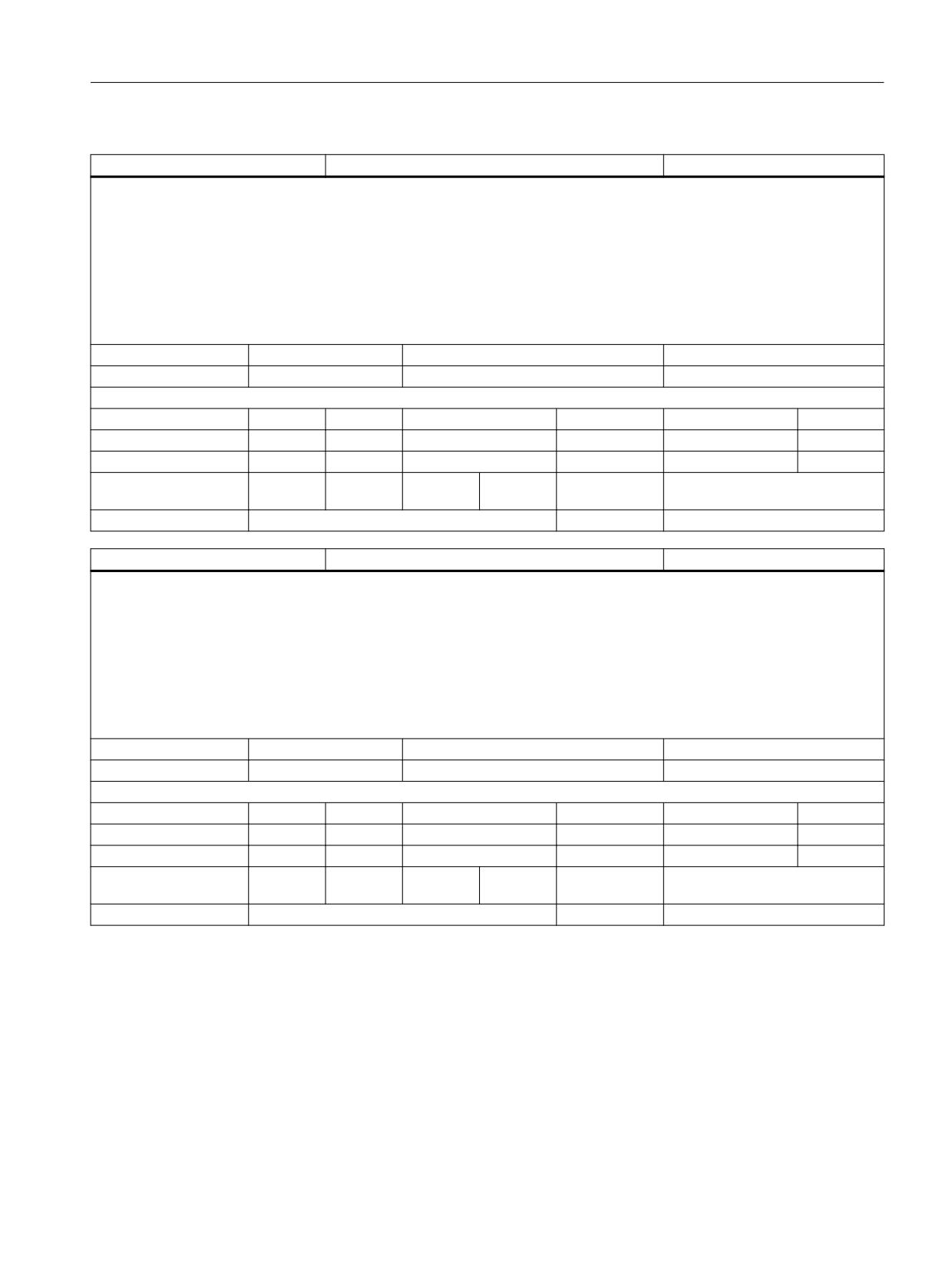
$AC_MEAS_P3_COORD
Coordinate system 3rd measuring point
INT
Description:
Variable for workpiece and tool measurement.
Variable $AC_MEAS_P3_COORD is used to set the coordinate system frame for the 3rd measuring point.
Application:
$AC_MEAS_P3_COORD = 0 ; WCS
$AC_MEAS_P3_COORD = 1 ; BCS
$AC_MEAS_P3_COORD = 2 ; MCS
$AC_MEAS_P3_COORD = 3 ; SZS
Unit
Init value
Min
Max
-
0
0
3
Read/Write properties:
TP
SA
TP/SA safety
NC-Variable
Safety
OEM-CC
Read:
X
-
7
X
7
-
Write:
X
-
7
X
7
-
Axis entry:
Overlap chan-
channel-specific
nel:
Scan mode:
Not classified
Link:
Not classified
$AC_MEAS_P4_COORD
Coordinate system 4th measuring point
INT
Description:
Variable for workpiece and tool measurement.
Variable $AC_MEAS_P4_COORD is used to set the coordinate system frame for the 4th measuring point.
Application:
$AC_MEAS_P4_COORD = 0 ; WCS
$AC_MEAS_P4_COORD = 1 ; BCS
$AC_MEAS_P4_COORD = 2 ; MCS
$AC_MEAS_P4_COORD = 3 ; SZS
Unit
Init value
Min
Max
-
0
0
3
Read/Write properties:
TP
SA
TP/SA safety
NC-Variable
Safety
OEM-CC
Read:
X
-
7
X
7
-
Write:
X
-
7
X
7
-
Axis entry:
Overlap chan-
channel-specific
nel:
Scan mode:
Not classified
Link:
Not classified
System variables
List Manual, 10/2020, 6FC5397-6AP40-6BA4
127
List of system variables
3.2 Channel-specific system variables
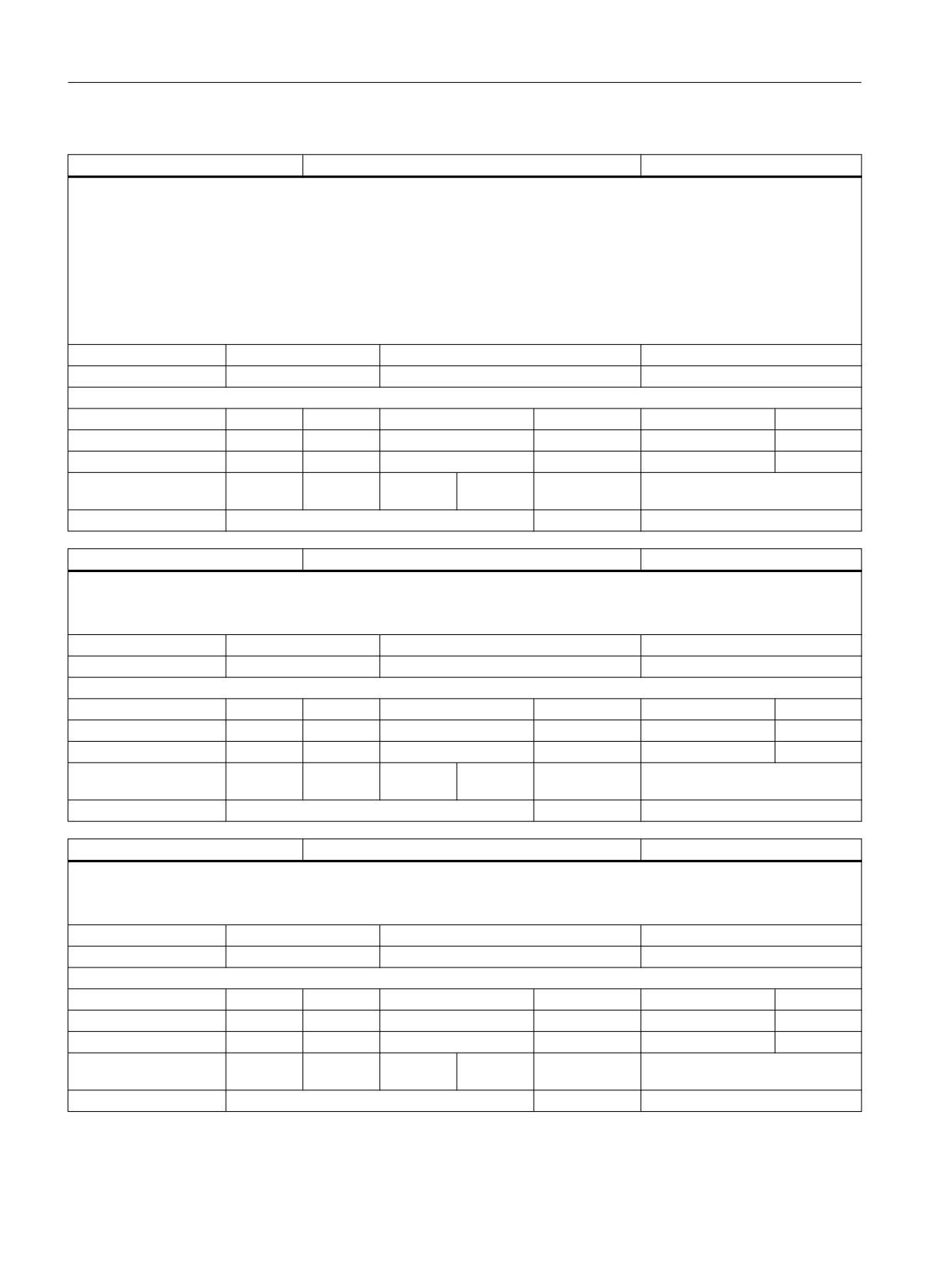
$AC_MEAS_SET_COORD
Coordinate system of position setpoint
INT
Description:
Variable for workpiece and tool measurement.
Variable $AC_MEAS_SET_COORD is used to set the coordinate system for the position setpoint.
Application:
$AC_MEAS_SET_COORD = 0 ; WCS
$AC_MEAS_SET_COORD = 1 ; BCS
$AC_MEAS_SET_COORD = 2 ; MCS
$AC_MEAS_SET_COORD = 3 ; SZS
Unit
Init value
Min
Max
-
0
0
3
Read/Write properties:
TP
SA
TP/SA safety
NC-Variable
Safety
OEM-CC
Read:
X
-
7
X
7
-
Write:
X
-
7
X
7
-
Axis entry:
Overlap chan-
channel-specific
nel:
Scan mode:
Not classified
Link:
Not classified
$AC_MEAS_WP_SETANGLE
Workpiece position angle setpoint
DOUBLE
Description:
Variable for workpiece and tool measurement.
Axial variable $AA_MEAS_WP_SETANGLE is used to define an angle setpoint for the workpiece position.
Unit
Init value
Min
Max
deg.
0.0
-1.8E+308
1.8E+308
Read/Write properties:
TP
SA
TP/SA safety
NC-Variable
Safety
OEM-CC
Read:
X
-
7
X
7
-
Write:
X
-
7
X
7
-
Axis entry:
Overlap chan-
channel-specific
nel:
Scan mode:
Not classified
Link:
Not classified
$AC_MEAS_CORNER_SETANGLE
Cutting angle setpoint for workpiece corner
DOUBLE
Description:
Variable for workpiece and tool measurement.
Variable $AA_MEAS_CORNER_SETANGLE is used to define an angle setpoint for the corner of a workpiece.
Unit
Init value
Min
Max
deg.
0.0
-1.8E+308
1.8E+308
Read/Write properties:
TP
SA
TP/SA safety
NC-Variable
Safety
OEM-CC
Read:
X
-
7
X
7
-
Write:
X
-
7
X
7
-
Axis entry:
Overlap chan-
channel-specific
nel:
Scan mode:
Not classified
Link:
Not classified
System variables
128
List Manual, 10/2020, 6FC5397-6AP40-6BA4
List of system variables
3.2 Channel-specific system variables
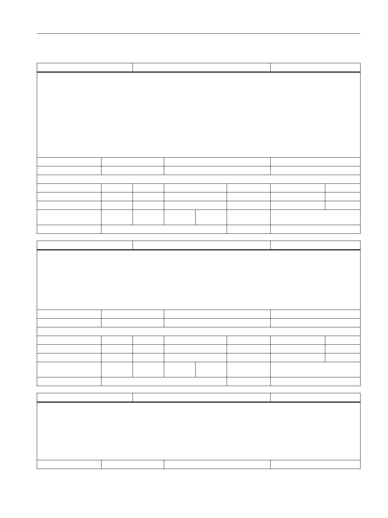
$AC_MEAS_DIR_APPROACH
Approach direction to workpiece
INT
Description:
Variable for workpiece and tool measurement.
Variable $AA_MEAS_DIR_APPROACH is used to define the direction of approach to the workpiece.
The following values are possible:
0:+x
1:-x
2:+y
3:-y
4:+z
5:-z
Unit
Init value
Min
Max
-
0
0
5
Read/Write properties:
TP
SA
TP/SA safety
NC-Variable
Safety
OEM-CC
Read:
X
-
7
X
7
-
Write:
X
-
7
X
7
-
Axis entry:
Overlap chan-
channel-specific
nel:
Scan mode:
Not classified
Link:
Not classified
$AC_MEAS_ACT_PLANE
Working plane for workpiece
INT
Description:
Variable for workpiece and tool measurement.
Variable $AC_MEAS_ACT_PLANE is used to define the working plane. The working plane is needed in order to define the tool orientation.
The following values are possible:
0: G17 working plane x/y infeed direction z
1: G18 working plane z/x infeed direction y
2: G19 working plane y/z infeed direction x
Unit
Init value
Min
Max
-
0
0
2
Read/Write properties:
TP
SA
TP/SA safety
NC-Variable
Safety
OEM-CC
Read:
X
-
7
X
7
-
Write:
X
-
7
X
7
-
Axis entry:
Overlap chan-
channel-specific
nel:
Scan mode:
Not classified
Link:
Not classified
$AC_MEAS_FINE_TRANS
Fine offset
INT
Description:
Variable for workpiece and tool measurement.
When measuring workpieces, translation offsets can be entered in the fine offset component of the selected frame. Variable
$AC_MEAS_FINE_TRANS is used for this purpose.
The following values are possible:
0: Translation offset is entered in coarse offset
1: Translation offset is entered in fine offset
Unit
Init value
Min
Max
System variables
List Manual, 10/2020, 6FC5397-6AP40-6BA4
129
List of system variables
3.2 Channel-specific system variables
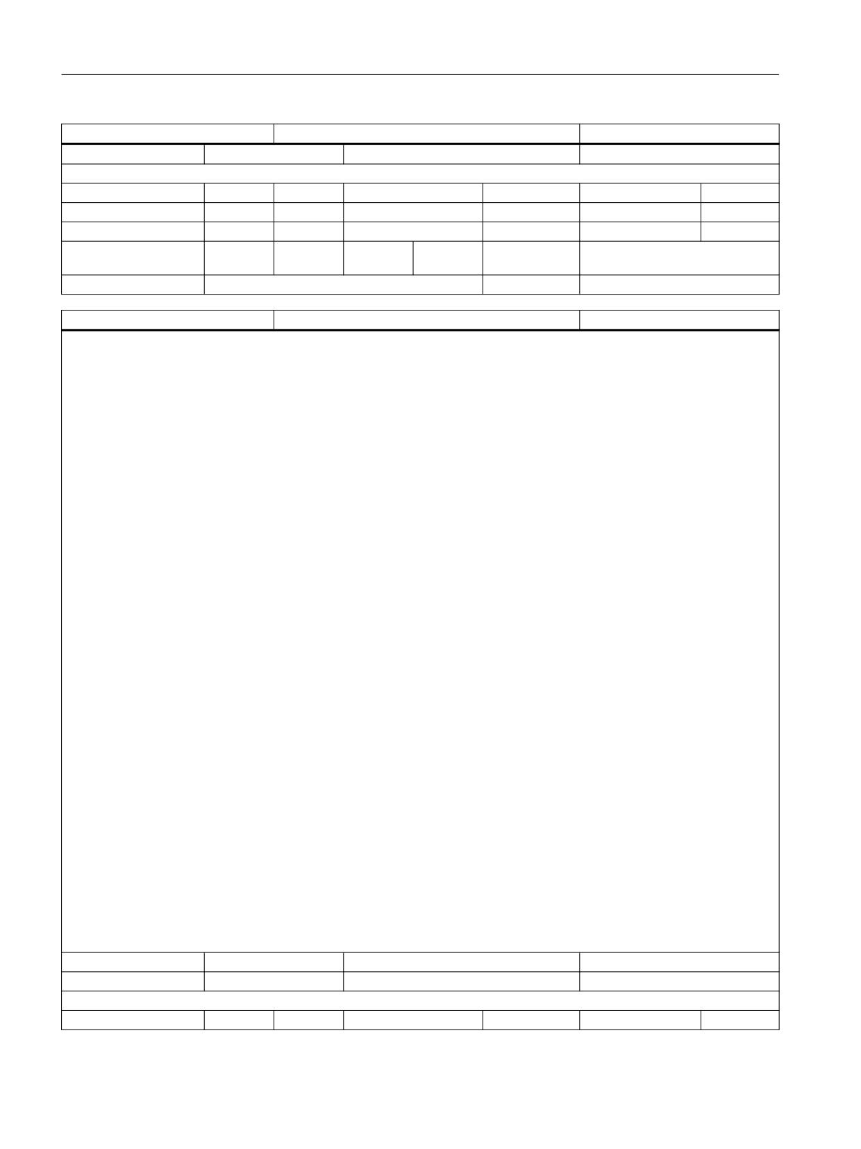
$AC_MEAS_FINE_TRANS
Fine offset
INT
-
0
0
1
Read/Write properties:
TP
SA
TP/SA safety
NC-Variable
Safety
OEM-CC
Read:
X
-
7
X
7
-
Write:
X
-
7
X
7
-
Axis entry:
Overlap chan-
channel-specific
nel:
Scan mode:
Not classified
Link:
Not classified
$AC_MEAS_FRAME_SELECT
Frame selection for workpiece measurement
INT
Description:
Variable for workpiece and tool measurement.
Variable $AC_MEAS_FRAME_SELECT is used to select the frame in which the calculated frame is entered.
The following values are possible:
0:
$P_SETFRAME
1:
$P_PARTFRAME
2:
$P_EXTFRAME
10..25:
$P_CHBFRAME[0..15]
50..65:
$P_NCBFRAME[0..15]
100..199: $P_IFRAME
500:
$P_TOOLFRAME
501:
$P_WPFRAME
502:
$P_TRAFRAME
503:
$P_PFRAME
504:
$P_CYCFRAME
505:
$P_RELFRAME (PCS)
506:
$P_RELFRAME (ACS)
1010..1025: $P_CHBFRAME[0..15], when G500 is active
1050..1065: $P_NCBFRAME[0..15], when G500 is active
2000:
$P_SETFR
2001:
$P_PARTFR
2002:
$P_EXTFR
2010..2025: $P_CHBFR[0..15]
2050..2065: $P_NCBFR[0..15]
2100..2199: $P_UIFR[0..99]
2500:
$P_TOOLFR
2501:
$P_WPFR
2502:
$P_TRAFR
2504:
$P_CYCFR
2505:
$P_RELFR (PCS)
2506:
$P_RELFR (ACS)
3010..3025: $P_CHBFR[0..15], when G500 is active
3050..3065: $P_NCBFR[0..15], when G500 is active
Unit
Init value
Min
Max
-
0
0
3065
Read/Write properties:
TP
SA
TP/SA safety
NC-Variable
Safety
OEM-CC
System variables
130
List Manual, 10/2020, 6FC5397-6AP40-6BA4
List of system variables
3.2 Channel-specific system variables
$AC_MEAS_FRAME_SELECT
Frame selection for workpiece measurement
INT
Read:
X
-
7
X
7
-
Write:
X
-
7
X
7
-
Axis entry:
Overlap chan-
channel-specific
nel:
Scan mode:
Not classified
Link:
Not classified
$AC_MEAS_CHSFR
Frame selection for system frames
INT
Description:
Variable for workpiece and tool measurement.
In order to convert a position from one coordinate system to another, $AC_MEAS_CHSFR can be used to define the composition of the desired
frame chain. The value of the variable should be selected according to the system frame bitmask $MC_MM_SYSTEM_FRAME_MASK.
Application:
$AC_MEAS_CHSFR = 'B1001'
Only the system frames for preset actual value and TOROT are included in the calculation of the new overall frame.
Unit
Init value
Min
Max
-
0
-2147483648
2147483647
Read/Write properties:
TP
SA
TP/SA safety
NC-Variable
Safety
OEM-CC
Read:
X
-
7
X
7
-
Write:
X
-
7
X
7
-
Axis entry:
Overlap chan-
channel-specific
nel:
Scan mode:
Not classified
Link:
Not classified
$AC_MEAS_NCBFR
Frame selection for global basic frames
INT
Description:
Variable for workpiece and tool measurement.
In order to convert a position from one coordinate system to another, $AC_MEAS_NCBFR can be used to define the composition of the desired
frame chain. The value of the variable should be interpreted as a bitmask from 0x0 to 0xFFFF for the global basic frames (up to 16 frames in
total).
Application:
$AC_MEAS_NCBFR = 'B11'
Only the first two global basic frames are included in the calculation of the new overall frame.
Unit
Init value
Min
Max
-
0
0
0xFFFF
Read/Write properties:
TP
SA
TP/SA safety
NC-Variable
Safety
OEM-CC
Read:
X
-
7
X
7
-
Write:
X
-
7
X
7
-
Axis entry:
Overlap chan-
channel-specific
nel:
Scan mode:
Not classified
Link:
Not classified
System variables
List Manual, 10/2020, 6FC5397-6AP40-6BA4
131
List of system variables
3.2 Channel-specific system variables
$AC_MEAS_CHBFR
Frame selection for channel basic frames
INT
Description:
Variable for workpiece and tool measurement.
In order to convert a position from one coordinate system to another, $AC_MEAS_CHBFR can be used to define the composition of the desired
frame chain. The value of the variable should be interpreted as a bitmask from 0x0 to 0xFFFF for the channel basic frames (up to 16 frames in
total).
Application:
$AC_MEAS_CHBFR = 'B11'
Only the first two channel basic frames are included in the calculation of the new overall frame.
Unit
Init value
Min
Max
-
0
0
0xFFFF
Read/Write properties:
TP
SA
TP/SA safety
NC-Variable
Safety
OEM-CC
Read:
X
-
7
X
7
-
Write:
X
-
7
X
7
-
Axis entry:
Overlap chan-
channel-specific
nel:
Scan mode:
Not classified
Link:
Not classified
$AC_MEAS_UIFR
Frame selection for settable frames
INT
Description:
Variable for workpiece and tool measurement.
In order to convert a position from one coordinate system to another, $AC_MEAS_UIFR can be used to define the composition of the desired
frame chain. The variable range for the settable frames is from 0 to 99 (up to 100 in total).
Application:
$AC_MEAS_UIFR = 1
The G54 frame is included in the calculation of the new overall frame.
Unit
Init value
Min
Max
-
0
0
99
Read/Write properties:
TP
SA
TP/SA safety
NC-Variable
Safety
OEM-CC
Read:
X
-
7
X
7
-
Write:
X
-
7
X
7
-
Axis entry:
Overlap chan-
channel-specific
nel:
Scan mode:
Not classified
Link:
Not classified
$AC_MEAS_PFRAME
Frame selection for the prog. frame
INT
Description:
Variable for workpiece and tool measurement.
In order to convert a position from one coordinate system to another, $AC_MEAS_PFRAME can be used to define the composition of the desired
frame chain.
The following values are allowed:
$AC_MEAS_PFRAME = 1 ; Programmable frame is not included in calculation
$AC_MEAS_PFRAME = 0 ; Programmable frame is included in calculation
Unit
Init value
Min
Max
-
0
0
1
Read/Write properties:
System variables
132
List Manual, 10/2020, 6FC5397-6AP40-6BA4
List of system variables
3.2 Channel-specific system variables
$AC_MEAS_PFRAME
Frame selection for the prog. frame
INT
TP
SA
TP/SA safety
NC-Variable
Safety
OEM-CC
Read:
X
-
7
X
7
-
Write:
X
-
7
X
7
-
Axis entry:
Overlap chan-
channel-specific
nel:
Scan mode:
Not classified
Link:
Not classified
$AC_MEAS_T_NUMBER
Tool selection
INT
Description:
Variable for workpiece and tool measurement.
Variable $AC_MEAS_T_NUMBER is used to select the tool for workpiece and tool measurement. The tool number of the active tool must match
the selected tool. The active tool is included in the calculation when T0 is selected. If no tool is selected, the tool selected by $AC_MEAS_T_NUM-
BER is used in the calculation.
Unit
Init value
Min
Max
-
0
0
2147483647
Read/Write properties:
TP
SA
TP/SA safety
NC-Variable
Safety
OEM-CC
Read:
X
-
7
X
7
-
Write:
X
-
7
X
7
-
Axis entry:
Overlap chan-
channel-specific
nel:
Scan mode:
Not classified
Link:
Not classified
$AC_MEAS_TOOL_MASK
Tool position
INT
Description:
Variable for workpiece and tool measurement.
Variable $AC_MEAS_TOOL_MASK specifies the tool position and considers the tool lengths for workpiece and tool measurement.
The following values are possible:
0x0: Default setting; all tool lengths are included
0x1: The radius of the tool is not included in the calculation
0x2: The tool is positioned in the x direction (G19)
0x4: The tool is positioned in the y direction (G18)
0x8: The tool is positioned in the z direction (G17)
0x10: The length of the tool is not included in the calculation.
0x20: The length of the active tool is included in the transformation of the coordinates of a position.
0x40: The tool is positioned in the x direction (G19)
0x80: The tool is positioned in the y direction (G18)
0x100: The tool is positioned in the z direction (G17)
0x200: Differences in the tool lengths are subtracted.
Whether or not the radius of a milling tool is included in the calculation is determined from the tool position and direction of approach. If the
direction of approach is not specified explicitly, it is derived from the selected plane. The direction of approach is in -z for G17, -y for G18 and
-x for G19.
Unit
Init value
Min
Max
-
0
0
0x10
Read/Write properties:
TP
SA
TP/SA safety
NC-Variable
Safety
OEM-CC
Read:
X
-
7
X
7
-
Write:
X
-
7
X
7
-
System variables
List Manual, 10/2020, 6FC5397-6AP40-6BA4
133
List of system variables
3.2 Channel-specific system variables
$AC_MEAS_TOOL_MASK
Tool position
INT
Axis entry:
Overlap chan-
channel-specific
nel:
Scan mode:
Not classified
Link:
Not classified
$AC_MEAS_D_NUMBER
Cutting edge selection
INT
Description:
Variable for workpiece and tool measurement.
Variable $AC_MEAS_D_NUMBER is used to select the tool cutting edge for workpiece and tool measurement. The tool cutting edge number of
the active tool must match the selected cutting edge. The active cutting edge is included in the calculation when D0 is selected. If no tool is
selected, the cutting edge selected by $AC_MEAS_D_NUMBER is used in the calculation.
Unit
Init value
Min
Max
-
0
0
2147483647
Read/Write properties:
TP
SA
TP/SA safety
NC-Variable
Safety
OEM-CC
Read:
X
-
7
X
7
-
Write:
X
-
7
X
7
-
Axis entry:
Overlap chan-
channel-specific
nel:
Scan mode:
Not classified
Link:
Not classified
System variables
134
List Manual, 10/2020, 6FC5397-6AP40-6BA4
List of system variables
3.2 Channel-specific system variables
$AC_MEAS_TYPE
Measurement type selection
INT
Description:
Variable for workpiece and tool measurement.
Variable $AC_MEAS_TYPE is used to select the type of measurement.
The following values are possible:
0: Default setting
1: x edge
2: y edge
3: z edge
4: Corner 1
5: Corner 2
6: Corner 3
7: Corner 4
8: Hole
9: Shaft
10: Tool length
11: Tool diameter
12: Groove
13: Web
14: Preset actual value memory for geo and special axes
15: Preset actual value memory for special axes only
16: Inclined edge
17: Plane_Angles (2 solid angles in one plane)
18: Plane_Normal (3 solid angles in one plane with specified setpoint)
19: Dimension_1 (1-dimensional setpoint specification)
20: Dimension_2 (2-dimensional setpoint specification)
21: Dimension_3 (3-dimensional setpoint specification)
22: ToolMagnifier (ShopTurn: Measurement of tool lengths with magnifier)
23: ToolMarkedPos (ShopTurn: Measurement of a tool length with marked position)
24: Coordinate transformation of a position
25: Rectangle
Unit
Init value
Min
Max
-
0
0
25
Read/Write properties:
TP
SA
TP/SA safety
NC-Variable
Safety
OEM-CC
Read:
X
-
7
X
7
-
Write:
X
-
7
X
7
-
Axis entry:
Overlap chan-
channel-specific
nel:
Scan mode:
Not classified
Link:
Not classified
System variables
List Manual, 10/2020, 6FC5397-6AP40-6BA4
135
List of system variables
3.2 Channel-specific system variables
$AC_MEAS_VALID
Validity bits of measurement variables.
INT
Description:
Variable for workpiece and tool measurement.
Variable $AC_MEAS_VALID is used to define which system variables are valid for the current measurement. The value should be set to 0 before
every measurement
The individual bits are set implicitly when the corresponding variables are written.
Bit 0:
$AA_MEAS_POINT1[axis]
Bit 1:
$AA_MEAS_POINT2[axis]
Bit 2:
$AA_MEAS_POINT3[axis]
Bit 3:
$AA_MEAS_POINT4[axis]
Bit 4:
$AA_MEAS_SETPOINT[axis]
Bit 5:
$AC_MEAS_WP_SETANGLE
Bit 6:
$AC_MEAS_CORNER_SETANGLE
Bit 7:
$AC_MEAS_T_NUMBER
Bit 8:
$AC_MEAS_D_NUMBER
Bit 9:
$AC_MEAS_DIR_APPROACH
Bit 10: $AC_MEAS_ACT_PLANE
Bit 11: $AC_MEAS_FRAME_SELECT
Bit 12: $AC_MEAS_TYPE
Bit 13: $AC_MEAS_FINE_TRANS
Bit 14: $AA_MEAS_SETANGLE[axis]
Bit 15: $AC_MEAS_SCALEUNIT
Bit 16: $AC_MEAS_TOOL_MASK
Bit 17: $AC_MEAS_P1_COORD
Bit 18: $AC_MEAS_P2_COORD
Bit 19: $AC_MEAS_P3_COORD
Bit 20: $AC_MEAS_P4_COORD
Bit 21: $AC_MEAS_SET_COORD
Bit 22: $AC_MEAS_CHSFR
Bit 23: $AC_MEAS_NCBFR
Bit 24: $AC_MEAS_CHBFR
Bit 25: $AC_MEAS_UIFR
Bit 26: $AC_MEAS_PFRAME
Bit 27: $AC_MEAS_INPUT
Bit 28: $AC_MEAS_GFR
Bit 29: $AC_MEAS_ORIWKS
Unit
Init value
Min
Max
-
0
-2147483648
2147483647
Read/Write properties:
TP
SA
TP/SA safety
NC-Variable
Safety
OEM-CC
Read:
X
-
7
X
7
-
Write:
X
-
7
X
7
-
Axis entry:
Overlap chan-
channel-specific
nel:
Scan mode:
Not classified
Link:
Not classified
System variables
136
List Manual, 10/2020, 6FC5397-6AP40-6BA4
List of system variables
3.2 Channel-specific system variables
$AC_MEAS_FRAME
Result frame for workpiece measurement
FRAME
Description:
Variable for workpiece and tool measurement.
Variable $AC_MEAS_FRAME is the result frame for workpiece measurement. This frame is calculated by the MEASURE() function or a PI service
and is not part of the active frame chain. The calculated result frame can then be copied into the selected frame ($AC_MEAS_FRAME_SELECT)
by the part program or a further PI service.
Unit
Init value
Min
Max
-
Read/Write properties:
TP
SA
TP/SA safety
NC-Variable
Safety
OEM-CC
Read:
X
-
7
X
7
-
Write:
X
-
7
-
0
-
Axis entry:
GEO
CHAN
MACH
SPIN
Overlap chan-
channel-specific
nel:
Scan mode:
Not classified
Link:
Not classified
$AC_MEAS_WP_ANGLE
Workpiece position angle
DOUBLE
Description:
Variable for workpiece and tool measurement.
Variable $AC_MEAS_WP_ANGLE is the calculated workpiece position angle for workpiece measurement. The value specifies the relative
position of the workpiece in the workpiece coordinate system (WCS).
Unit
Init value
Min
Max
deg.
0.0
-1.8E+308
1.8E+308
Read/Write properties:
TP
SA
TP/SA safety
NC-Variable
Safety
OEM-CC
Read:
X
-
7
X
7
-
Write:
-
-
0
-
0
-
Axis entry:
Overlap chan-
channel-specific
nel:
Scan mode:
Not classified
Link:
Not classified
$AC_MEAS_CORNER_ANGLE
Angle of a corner
DOUBLE
Description:
Variable for workpiece and tool measurement.
Variable $AC_MEAS_CORNER_ANGLE is the calculated cutting angle of the corner for workpiece measurement.
Unit
Init value
Min
Max
deg.
0.0
-1.8E+308
1.8E+308
Read/Write properties:
TP
SA
TP/SA safety
NC-Variable
Safety
OEM-CC
Read:
X
-
7
X
7
-
Write:
-
-
0
-
0
-
Axis entry:
Overlap chan-
channel-specific
nel:
Scan mode:
Not classified
Link:
Not classified
System variables
List Manual, 10/2020, 6FC5397-6AP40-6BA4
137
List of system variables
3.2 Channel-specific system variables
$AC_MEAS_DIAMETER
Tool diameter
DOUBLE
Description:
Variable for workpiece and tool measurement.
Variable $AC_MEAS_DIAMETER is the calculated diameter for tool measurement.
Unit
Init value
Min
Max
mm
0.0
-1.8E+308
1.8E+308
Read/Write properties:
TP
SA
TP/SA safety
NC-Variable
Safety
OEM-CC
Read:
X
-
7
X
7
-
Write:
-
-
0
-
0
-
Axis entry:
Overlap chan-
channel-specific
nel:
Scan mode:
Not classified
Link:
Not classified
$AC_MEAS_TOOL_LENGTH
Tool length
DOUBLE
Description:
Variable for workpiece and tool measurement.
Variable $AC_MEAS_TOOL_LENGTH is the calculated tool length for tool measurement.
Unit
Init value
Min
Max
mm
0.0
-1.8E+308
1.8E+308
Read/Write properties:
TP
SA
TP/SA safety
NC-Variable
Safety
OEM-CC
Read:
X
-
7
X
7
-
Write:
-
-
0
-
0
-
Axis entry:
Overlap chan-
channel-specific
nel:
Scan mode:
Not classified
Link:
Not classified
$AC_MEAS_RESULTS [10]
Measurement results
DOUBLE
Description:
Variable for workpiece and tool measurement.
Array variable $AC_MEAS_RESULTS[n] contains the calculation results. The measurement type ($AC_MEAS_TYPE) determines which elements
of the array are written.
Index 1:
Measurement results
Unit
Init value
Min
Max
-
0.0
-1.8E+308
1.8E+308
Read/Write properties:
TP
SA
TP/SA safety
NC-Variable
Safety
OEM-CC
Read:
X
-
7
X
7
-
Write:
-
-
0
-
0
-
Axis entry:
Overlap chan-
channel-specific
nel:
Scan mode:
Not classified
Link:
Not classified
System variables
138
List Manual, 10/2020, 6FC5397-6AP40-6BA4
List of system variables
3.2 Channel-specific system variables
$AC_MEAS_SCALEUNIT
Measurement unit
INT
Description:
Variable for workpiece and tool measurement.
The variable $AC_MEAS_SCALEUNIT specifies the unit of measurement according to the configuration of the input and output values.
The following values are possible:
0: The unit of measurement depends on the active G code INCH: G70/G700 METRIC: G71/G710
1: The unit of measurement corresponds to the configuration (default setting)
Unit
Init value
Min
Max
-
1
0
1
Read/Write properties:
TP
SA
TP/SA safety
NC-Variable
Safety
OEM-CC
Read:
X
-
7
X
7
-
Write:
X
-
7
X
7
-
Axis entry:
Overlap chan-
channel-specific
nel:
Scan mode:
Not classified
Link:
Not classified
$P_CHANNO
-
INT
Description:
Interrogate current channel number.
Unit
Init value
Min
Max
-
0
1
10
Read/Write properties:
TP
SA
TP/SA safety
NC-Variable
Safety
OEM-CC
Read:
X
-
7
-
0
-
Write:
-
-
0
-
0
-
Axis entry:
Overlap chan-
channel-specific
nel:
Scan mode:
Not classified
Link:
Not classified
$AC_SERUPRO
-
INT
Description:
$AC_SERUPRO
Interrogate whether search type Serupro is active. (Serupro: "Block search via program test")
Can be used in Synacts and the part program
$AC_SERUPRO == 0 Search type Serupro is not active
$AC_SERUPRO == 1 Search type Serupro is active
Unit
Init value
Min
Max
-
0
0
1
Read/Write properties:
TP
SA
TP/SA safety
NC-Variable
Safety
OEM-CC
Read:
X
X
7
X
7
X
Write:
-
-
0
-
0
-
Axis entry:
Overlap chan-
channel-specific
nel:
Scan mode:
Not classified
Link:
No restrictions
System variables
List Manual, 10/2020, 6FC5397-6AP40-6BA4
139
List of system variables
3.2 Channel-specific system variables
$AC_VACTBF
Path velocity in the BCS
DOUBLE
Description:
$AC_VACTBF supplies the path velocity in the basic coordinate system. FGroup and FGREF are taken into account.
Unit
Init value
Min
Max
Linear / angular speed
0.0
-1.8E+308
1.8E+308
Read/Write properties:
TP
SA
TP/SA safety
NC-Variable
Safety
OEM-CC
Read:
-
X
0
X
7
-
Write:
-
-
0
-
0
-
Axis entry:
Overlap chan-
channel-specific
nel:
Scan mode:
Not classified
Link:
Not classified
$AC_VACTWF
Path velocity in the WCS
DOUBLE
Description:
Path velocity in workpiece coordinate system. FGROUP and FGREF are taken into account.
Unit
Init value
Min
Max
Linear / angular speed
0.0
-1.8E+308
1.8E+308
Read/Write properties:
TP
SA
TP/SA safety
NC-Variable
Safety
OEM-CC
Read:
-
X
0
-
0
-
Write:
-
-
0
-
0
-
Axis entry:
Overlap chan-
channel-specific
nel:
Scan mode:
Not classified
Link:
Not classified
$P_CHBFR0
Access to 1st channel basic frame
FRAME
Description:
Access to 1st channel basic frame. Corresponds to $P_CHBFR[0].
Unit
Init value
Min
Max
-
Read/Write properties:
TP
SA
TP/SA safety
NC-Variable
Safety
OEM-CC
Read:
X
-
7
-
0
-
Write:
X
-
7
-
0
-
Axis entry:
GEO
CHAN
MACH
Overlap chan-
channel-specific
nel:
Scan mode:
Not classified
Link:
No restrictions
$P_CHBFR1
Access to 2nd channel basic frame
FRAME
Description:
Access to 2nd channel basic frame. Corresponds to $P_CHBFR[1].
Unit
Init value
Min
Max
-
Read/Write properties:
TP
SA
TP/SA safety
NC-Variable
Safety
OEM-CC
Read:
X
-
7
-
0
-
System variables
140
List Manual, 10/2020, 6FC5397-6AP40-6BA4
List of system variables
3.2 Channel-specific system variables
$P_CHBFR1
Access to 2nd channel basic frame
FRAME
Write:
X
-
7
-
0
-
Axis entry:
GEO
CHAN
MACH
Overlap chan-
channel-specific
nel:
Scan mode:
Not classified
Link:
No restrictions
$P_CHBFR2
Access to 3rd channel basic frame
FRAME
Description:
Access to 3rd channel basic frame. Corresponds to $P_CHBFR[2].
Unit
Init value
Min
Max
-
Read/Write properties:
TP
SA
TP/SA safety
NC-Variable
Safety
OEM-CC
Read:
X
-
7
-
0
-
Write:
X
-
7
-
0
-
Axis entry:
GEO
CHAN
MACH
Overlap chan-
channel-specific
nel:
Scan mode:
Not classified
Link:
No restrictions
$P_CHBFR3
Access to 4th channel basic frame
FRAME
Description:
Access to 4th channel basic frame. Corresponds to $P_CHBFR[3].
Unit
Init value
Min
Max
-
Read/Write properties:
TP
SA
TP/SA safety
NC-Variable
Safety
OEM-CC
Read:
X
-
7
-
0
-
Write:
X
-
7
-
0
-
Axis entry:
GEO
CHAN
MACH
Overlap chan-
channel-specific
nel:
Scan mode:
Not classified
Link:
No restrictions
$P_CHBFR4
Access to 5th channel basic frame
FRAME
Description:
Access to 5th channel basic frame. Corresponds to $P_CHBFR[4].
Unit
Init value
Min
Max
-
Read/Write properties:
TP
SA
TP/SA safety
NC-Variable
Safety
OEM-CC
Read:
X
-
7
-
0
-
Write:
X
-
7
-
0
-
Axis entry:
GEO
CHAN
MACH
Overlap chan-
channel-specific
nel:
Scan mode:
Not classified
Link:
No restrictions
System variables
List Manual, 10/2020, 6FC5397-6AP40-6BA4
141
List of system variables
3.2 Channel-specific system variables
$P_CHBFR5
Access to 6th channel basic frame
FRAME
Description:
Access to 6th channel basic frame. Corresponds to $P_CHBFR[5].
Unit
Init value
Min
Max
-
Read/Write properties:
TP
SA
TP/SA safety
NC-Variable
Safety
OEM-CC
Read:
X
-
7
-
0
-
Write:
X
-
7
-
0
-
Axis entry:
GEO
CHAN
MACH
Overlap chan-
channel-specific
nel:
Scan mode:
Not classified
Link:
No restrictions
$P_CHBFR6
Access to 7th channel basic frame
FRAME
Description:
Access to 7th channel basic frame. Corresponds to $P_CHBFR[6].
Unit
Init value
Min
Max
-
Read/Write properties:
TP
SA
TP/SA safety
NC-Variable
Safety
OEM-CC
Read:
X
-
7
-
0
-
Write:
X
-
7
-
0
-
Axis entry:
GEO
CHAN
MACH
Overlap chan-
channel-specific
nel:
Scan mode:
Not classified
Link:
No restrictions
$P_CHBFR7
Access to 8th channel basic frame
FRAME
Description:
Access to 8th channel basic frame. Corresponds to $P_CHBFR[7].
Unit
Init value
Min
Max
-
Read/Write properties:
TP
SA
TP/SA safety
NC-Variable
Safety
OEM-CC
Read:
X
-
7
-
0
-
Write:
X
-
7
-
0
-
Axis entry:
GEO
CHAN
MACH
Overlap chan-
channel-specific
nel:
Scan mode:
Not classified
Link:
No restrictions
$P_CHBFR8
Access to 9th channel basic frame
FRAME
Description:
Access to 9th channel basic frame. Corresponds to $P_CHBFR[8].
Unit
Init value
Min
Max
-
Read/Write properties:
TP
SA
TP/SA safety
NC-Variable
Safety
OEM-CC
Read:
X
-
7
-
0
-
System variables
142
List Manual, 10/2020, 6FC5397-6AP40-6BA4
List of system variables
3.2 Channel-specific system variables
$P_CHBFR8
Access to 9th channel basic frame
FRAME
Write:
X
-
7
-
0
-
Axis entry:
GEO
CHAN
MACH
Overlap chan-
channel-specific
nel:
Scan mode:
Not classified
Link:
No restrictions
$P_CHBFR9
Access to 10th channel basic frame
FRAME
Description:
Access to 10th channel basic frame. Corresponds to $P_CHBFR[9].
Unit
Init value
Min
Max
-
Read/Write properties:
TP
SA
TP/SA safety
NC-Variable
Safety
OEM-CC
Read:
X
-
7
-
0
-
Write:
X
-
7
-
0
-
Axis entry:
GEO
CHAN
MACH
Overlap chan-
channel-specific
nel:
Scan mode:
Not classified
Link:
No restrictions
$P_CHBFR10
Access to 11th channel basic frame
FRAME
Description:
Access to 11th channel basic frame. Corresponds to $P_CHBFR[10].
Unit
Init value
Min
Max
-
Read/Write properties:
TP
SA
TP/SA safety
NC-Variable
Safety
OEM-CC
Read:
X
-
7
-
0
-
Write:
X
-
7
-
0
-
Axis entry:
GEO
CHAN
MACH
Overlap chan-
channel-specific
nel:
Scan mode:
Not classified
Link:
No restrictions
$P_CHBFR11
Access to 12th channel basic frame
FRAME
Description:
Access to 12th channel basic frame. Corresponds to $P_CHBFR[11].
Unit
Init value
Min
Max
-
Read/Write properties:
TP
SA
TP/SA safety
NC-Variable
Safety
OEM-CC
Read:
X
-
7
-
0
-
Write:
X
-
7
-
0
-
Axis entry:
GEO
CHAN
MACH
Overlap chan-
channel-specific
nel:
Scan mode:
Not classified
Link:
No restrictions
System variables
List Manual, 10/2020, 6FC5397-6AP40-6BA4
143
List of system variables
3.2 Channel-specific system variables
$P_CHBFR12
Access to 13th channel basic frame
FRAME
Description:
Access to 13th channel basic frame. Corresponds to $P_CHBFR[12].
Unit
Init value
Min
Max
-
Read/Write properties:
TP
SA
TP/SA safety
NC-Variable
Safety
OEM-CC
Read:
X
-
7
-
0
-
Write:
X
-
7
-
0
-
Axis entry:
GEO
CHAN
MACH
Overlap chan-
channel-specific
nel:
Scan mode:
Not classified
Link:
No restrictions
$P_CHBFR13
Access to 14th channel basic frame
FRAME
Description:
Access to 14th channel basic frame. Corresponds to $P_CHBFR[13].
Unit
Init value
Min
Max
-
Read/Write properties:
TP
SA
TP/SA safety
NC-Variable
Safety
OEM-CC
Read:
X
-
7
-
0
-
Write:
X
-
7
-
0
-
Axis entry:
GEO
CHAN
MACH
Overlap chan-
channel-specific
nel:
Scan mode:
Not classified
Link:
No restrictions
$P_CHBFR14
Access to 15th channel basic frame
FRAME
Description:
Access to 15th channel basic frame. Corresponds to $P_CHBFR[14].
Unit
Init value
Min
Max
-
Read/Write properties:
TP
SA
TP/SA safety
NC-Variable
Safety
OEM-CC
Read:
X
-
7
-
0
-
Write:
X
-
7
-
0
-
Axis entry:
GEO
CHAN
MACH
Overlap chan-
channel-specific
nel:
Scan mode:
Not classified
Link:
No restrictions
$P_CHBFR15
Access to 16th channel basic frame
FRAME
Description:
Access to 16th channel basic frame. Corresponds to $P_CHBFR[15].
Unit
Init value
Min
Max
-
Read/Write properties:
TP
SA
TP/SA safety
NC-Variable
Safety
OEM-CC
Read:
X
-
7
-
0
-
System variables
144
List Manual, 10/2020, 6FC5397-6AP40-6BA4
List of system variables
3.2 Channel-specific system variables
$P_CHBFR15
Access to 16th channel basic frame
FRAME
Write:
X
-
7
-
0
-
Axis entry:
GEO
CHAN
MACH
Overlap chan-
channel-specific
nel:
Scan mode:
Not classified
Link:
No restrictions
$P_NCBFR0
Access to 1st NCU-global basic frame
FRAME
Description:
Access to 1st NCU-global basic frame. Corresponds to $P_NCBFR[0].
Unit
Init value
Min
Max
-
Read/Write properties:
TP
SA
TP/SA safety
NC-Variable
Safety
OEM-CC
Read:
X
-
7
-
0
-
Write:
X
-
7
-
0
-
Axis entry:
GEO
CHAN
MACH
Overlap chan-
channel-specific
nel:
Scan mode:
Not classified
Link:
No restrictions
$P_NCBFR1
Access to 2nd NCU-global basic frame
FRAME
Description:
Access to 2nd NCU-global basic frame. Corresponds to $P_NCBFR[1].
Unit
Init value
Min
Max
-
Read/Write properties:
TP
SA
TP/SA safety
NC-Variable
Safety
OEM-CC
Read:
X
-
7
-
0
-
Write:
X
-
7
-
0
-
Axis entry:
GEO
CHAN
MACH
Overlap chan-
channel-specific
nel:
Scan mode:
Not classified
Link:
No restrictions
$P_NCBFR2
Access to 3rd NCU-global basic frame
FRAME
Description:
Access to 3rd NCU-global basic frame. Corresponds to $P_NCBFR[2].
Unit
Init value
Min
Max
-
Read/Write properties:
TP
SA
TP/SA safety
NC-Variable
Safety
OEM-CC
Read:
X
-
7
-
0
-
Write:
X
-
7
-
0
-
Axis entry:
GEO
CHAN
MACH
Overlap chan-
channel-specific
nel:
Scan mode:
Not classified
Link:
No restrictions
System variables
List Manual, 10/2020, 6FC5397-6AP40-6BA4
145
List of system variables
3.2 Channel-specific system variables
$P_NCBFR3
Access to 4th NCU-global basic frame
FRAME
Description:
Access to 4th NCU-global basic frame. Corresponds to $P_NCBFR[3].
Unit
Init value
Min
Max
-
Read/Write properties:
TP
SA
TP/SA safety
NC-Variable
Safety
OEM-CC
Read:
X
-
7
-
0
-
Write:
X
-
7
-
0
-
Axis entry:
GEO
CHAN
MACH
Overlap chan-
channel-specific
nel:
Scan mode:
Not classified
Link:
No restrictions
$P_NCBFR4
Access to 5th NCU-global basic frame
FRAME
Description:
Access to 5th NCU-global basic frame. Corresponds to $P_NCBFR[4].
Unit
Init value
Min
Max
-
Read/Write properties:
TP
SA
TP/SA safety
NC-Variable
Safety
OEM-CC
Read:
X
-
7
-
0
-
Write:
X
-
7
-
0
-
Axis entry:
GEO
CHAN
MACH
Overlap chan-
channel-specific
nel:
Scan mode:
Not classified
Link:
No restrictions
$P_NCBFR5
Access to 6th NCU-global basic frame
FRAME
Description:
Access to 6th NCU-global basic frame. Corresponds to $P_NCBFR[5].
Unit
Init value
Min
Max
-
Read/Write properties:
TP
SA
TP/SA safety
NC-Variable
Safety
OEM-CC
Read:
X
-
7
-
0
-
Write:
X
-
7
-
0
-
Axis entry:
GEO
CHAN
MACH
Overlap chan-
channel-specific
nel:
Scan mode:
Not classified
Link:
No restrictions
$P_NCBFR6
Access to 7th NCU-global basic frame
FRAME
Description:
Access to 7th NCU-global basic frame. Corresponds to $P_NCBFR[6].
Unit
Init value
Min
Max
-
Read/Write properties:
TP
SA
TP/SA safety
NC-Variable
Safety
OEM-CC
Read:
X
-
7
-
0
-
System variables
146
List Manual, 10/2020, 6FC5397-6AP40-6BA4
List of system variables
3.2 Channel-specific system variables
$P_NCBFR6
Access to 7th NCU-global basic frame
FRAME
Write:
X
-
7
-
0
-
Axis entry:
GEO
CHAN
MACH
Overlap chan-
channel-specific
nel:
Scan mode:
Not classified
Link:
No restrictions
$P_NCBFR7
Access to 8th NCU-global basic frame
FRAME
Description:
Access to 8th NCU-global basic frame. Corresponds to $P_NCBFR[7].
Unit
Init value
Min
Max
-
Read/Write properties:
TP
SA
TP/SA safety
NC-Variable
Safety
OEM-CC
Read:
X
-
7
-
0
-
Write:
X
-
7
-
0
-
Axis entry:
GEO
CHAN
MACH
Overlap chan-
channel-specific
nel:
Scan mode:
Not classified
Link:
No restrictions
$P_NCBFR8
Access to 9th NCU-global basic frame
FRAME
Description:
Access to 9th NCU-global basic frame. Corresponds to $P_NCBFR[8].
Unit
Init value
Min
Max
-
Read/Write properties:
TP
SA
TP/SA safety
NC-Variable
Safety
OEM-CC
Read:
X
-
7
-
0
-
Write:
X
-
7
-
0
-
Axis entry:
GEO
CHAN
MACH
Overlap chan-
channel-specific
nel:
Scan mode:
Not classified
Link:
No restrictions
$P_NCBFR9
Access to 10th NCU-global basic frame
FRAME
Description:
Access to 10th NCU-global basic frame. Corresponds to $P_NCBFR[9].
Unit
Init value
Min
Max
-
Read/Write properties:
TP
SA
TP/SA safety
NC-Variable
Safety
OEM-CC
Read:
X
-
7
-
0
-
Write:
X
-
7
-
0
-
Axis entry:
GEO
CHAN
MACH
Overlap chan-
channel-specific
nel:
Scan mode:
Not classified
Link:
No restrictions
System variables
List Manual, 10/2020, 6FC5397-6AP40-6BA4
147
List of system variables
3.2 Channel-specific system variables
$P_NCBFR10
Access to 11th NCU-global basic frame
FRAME
Description:
Access to 11th NCU-global basic frame. Corresponds to $P_NCBFR[10].
Unit
Init value
Min
Max
-
Read/Write properties:
TP
SA
TP/SA safety
NC-Variable
Safety
OEM-CC
Read:
X
-
7
-
0
-
Write:
X
-
7
-
0
-
Axis entry:
GEO
CHAN
MACH
Overlap chan-
channel-specific
nel:
Scan mode:
Not classified
Link:
No restrictions
$P_NCBFR11
Access to 12th NCU-global basic frame
FRAME
Description:
Access to 12th NCU-global basic frame. Corresponds to $P_NCBFR[11].
Unit
Init value
Min
Max
-
Read/Write properties:
TP
SA
TP/SA safety
NC-Variable
Safety
OEM-CC
Read:
X
-
7
-
0
-
Write:
X
-
7
-
0
-
Axis entry:
GEO
CHAN
MACH
Overlap chan-
channel-specific
nel:
Scan mode:
Not classified
Link:
No restrictions
$P_NCBFR12
Access to 13th NCU-global basic frame
FRAME
Description:
Access to 13th NCU-global basic frame. Corresponds to $P_NCBFR[12].
Unit
Init value
Min
Max
-
Read/Write properties:
TP
SA
TP/SA safety
NC-Variable
Safety
OEM-CC
Read:
X
-
7
-
0
-
Write:
X
-
7
-
0
-
Axis entry:
GEO
CHAN
MACH
Overlap chan-
channel-specific
nel:
Scan mode:
Not classified
Link:
No restrictions
$P_NCBFR13
Access to 14th NCU-global basic frame
FRAME
Description:
Access to 14th NCU-global basic frame. Corresponds to $P_NCBFR[13].
Unit
Init value
Min
Max
-
Read/Write properties:
TP
SA
TP/SA safety
NC-Variable
Safety
OEM-CC
Read:
X
-
7
-
0
-
System variables
148
List Manual, 10/2020, 6FC5397-6AP40-6BA4
List of system variables
3.2 Channel-specific system variables
$P_NCBFR13
Access to 14th NCU-global basic frame
FRAME
Write:
X
-
7
-
0
-
Axis entry:
GEO
CHAN
MACH
Overlap chan-
channel-specific
nel:
Scan mode:
Not classified
Link:
No restrictions
$P_NCBFR14
Access to 15th NCU-global basic frame
FRAME
Description:
Access to 15th NCU-global basic frame. Corresponds to $P_NCBFR[14].
Unit
Init value
Min
Max
-
Read/Write properties:
TP
SA
TP/SA safety
NC-Variable
Safety
OEM-CC
Read:
X
-
7
-
0
-
Write:
X
-
7
-
0
-
Axis entry:
GEO
CHAN
MACH
Overlap chan-
channel-specific
nel:
Scan mode:
Not classified
Link:
No restrictions
$P_NCBFR15
Access to 16th NCU-global basic frame
FRAME
Description:
Access to 16th NCU-global basic frame. Corresponds to $P_NCBFR[15].
Unit
Init value
Min
Max
-
Read/Write properties:
TP
SA
TP/SA safety
NC-Variable
Safety
OEM-CC
Read:
X
-
7
-
0
-
Write:
X
-
7
-
0
-
Axis entry:
GEO
CHAN
MACH
Overlap chan-
channel-specific
nel:
Scan mode:
Not classified
Link:
No restrictions
$P_CHBFRAME0
Access to 1st current channel basic frame
FRAME
Description:
Access to 1st current channel basic frame. Corresponds to $P_CHBFRAME[0].
Unit
Init value
Min
Max
-
Read/Write properties:
TP
SA
TP/SA safety
NC-Variable
Safety
OEM-CC
Read:
X
-
7
-
0
-
Write:
X
-
7
-
0
-
Axis entry:
GEO
CHAN
MACH
Overlap chan-
channel-specific
nel:
Scan mode:
Not classified
Link:
No restrictions
System variables
List Manual, 10/2020, 6FC5397-6AP40-6BA4
149
List of system variables
3.2 Channel-specific system variables
$P_CHBFRAME1
Access to 2nd current channel basic frame
FRAME
Description:
Access to 2nd current channel basic frame. Corresponds to $P_CHBFRAME[1].
Unit
Init value
Min
Max
-
Read/Write properties:
TP
SA
TP/SA safety
NC-Variable
Safety
OEM-CC
Read:
X
-
7
-
0
-
Write:
X
-
7
-
0
-
Axis entry:
GEO
CHAN
MACH
Overlap chan-
channel-specific
nel:
Scan mode:
Not classified
Link:
No restrictions
$P_CHBFRAME2
Access to 3rd current channel basic frame
FRAME
Description:
Access to 3rd current channel basic frame. Corresponds to $P_CHBFRAME[2].
Unit
Init value
Min
Max
-
Read/Write properties:
TP
SA
TP/SA safety
NC-Variable
Safety
OEM-CC
Read:
X
-
7
-
0
-
Write:
X
-
7
-
0
-
Axis entry:
GEO
CHAN
MACH
Overlap chan-
channel-specific
nel:
Scan mode:
Not classified
Link:
No restrictions
$P_CHBFRAME3
Access to 4th current channel basic frame
FRAME
Description:
Access to 4th current channel basic frame. Corresponds to $P_CHBFRAME[3].
Unit
Init value
Min
Max
-
Read/Write properties:
TP
SA
TP/SA safety
NC-Variable
Safety
OEM-CC
Read:
X
-
7
-
0
-
Write:
X
-
7
-
0
-
Axis entry:
GEO
CHAN
MACH
Overlap chan-
channel-specific
nel:
Scan mode:
Not classified
Link:
No restrictions
$P_CHBFRAME4
Access to 5th current channel basic frame
FRAME
Description:
Access to 5th current channel basic frame. Corresponds to $P_CHBFRAME[4].
Unit
Init value
Min
Max
-
Read/Write properties:
TP
SA
TP/SA safety
NC-Variable
Safety
OEM-CC
Read:
X
-
7
-
0
-
System variables
150
List Manual, 10/2020, 6FC5397-6AP40-6BA4
List of system variables
3.2 Channel-specific system variables
$P_CHBFRAME4
Access to 5th current channel basic frame
FRAME
Write:
X
-
7
-
0
-
Axis entry:
GEO
CHAN
MACH
Overlap chan-
channel-specific
nel:
Scan mode:
Not classified
Link:
No restrictions
$P_CHBFRAME5
Access to 6th current channel basic frame
FRAME
Description:
Access to 6th current channel basic frame. Corresponds to $P_CHBFRAME[5].
Unit
Init value
Min
Max
-
Read/Write properties:
TP
SA
TP/SA safety
NC-Variable
Safety
OEM-CC
Read:
X
-
7
-
0
-
Write:
X
-
7
-
0
-
Axis entry:
GEO
CHAN
MACH
Overlap chan-
channel-specific
nel:
Scan mode:
Not classified
Link:
No restrictions
$P_CHBFRAME6
Access to 7th current channel basic frame
FRAME
Description:
Access to 7th current channel basic frame. Corresponds to $P_CHBFRAME[6].
Unit
Init value
Min
Max
-
Read/Write properties:
TP
SA
TP/SA safety
NC-Variable
Safety
OEM-CC
Read:
X
-
7
-
0
-
Write:
X
-
7
-
0
-
Axis entry:
GEO
CHAN
MACH
Overlap chan-
channel-specific
nel:
Scan mode:
Not classified
Link:
No restrictions
$P_CHBFRAME7
Access to 8th current channel basic frame
FRAME
Description:
Access to 8th current channel basic frame. Corresponds to $P_CHBFRAME[7].
Unit
Init value
Min
Max
-
Read/Write properties:
TP
SA
TP/SA safety
NC-Variable
Safety
OEM-CC
Read:
X
-
7
-
0
-
Write:
X
-
7
-
0
-
Axis entry:
GEO
CHAN
MACH
Overlap chan-
channel-specific
nel:
Scan mode:
Not classified
Link:
No restrictions
System variables
List Manual, 10/2020, 6FC5397-6AP40-6BA4
151
List of system variables
3.2 Channel-specific system variables
$P_CHBFRAME8
Access to 9th current channel basic frame
FRAME
Description:
Access to 9th current channel basic frame. Corresponds to $P_CHBFRAME[8].
Unit
Init value
Min
Max
-
Read/Write properties:
TP
SA
TP/SA safety
NC-Variable
Safety
OEM-CC
Read:
X
-
7
-
0
-
Write:
X
-
7
-
0
-
Axis entry:
GEO
CHAN
MACH
Overlap chan-
channel-specific
nel:
Scan mode:
Not classified
Link:
No restrictions
$P_CHBFRAME9
Access to 10th current channel basic frame
FRAME
Description:
Access to 10th current channel basic frame. Corresponds to $P_CHBFRAME[9].
Unit
Init value
Min
Max
-
Read/Write properties:
TP
SA
TP/SA safety
NC-Variable
Safety
OEM-CC
Read:
X
-
7
-
0
-
Write:
X
-
7
-
0
-
Axis entry:
GEO
CHAN
MACH
Overlap chan-
channel-specific
nel:
Scan mode:
Not classified
Link:
No restrictions
$P_CHBFRAME10
Access to 11th current channel basic frame
FRAME
Description:
Access to 11th current channel basic frame. Corresponds to $P_CHBFRAME[10].
Unit
Init value
Min
Max
-
Read/Write properties:
TP
SA
TP/SA safety
NC-Variable
Safety
OEM-CC
Read:
X
-
7
-
0
-
Write:
X
-
7
-
0
-
Axis entry:
GEO
CHAN
MACH
Overlap chan-
channel-specific
nel:
Scan mode:
Not classified
Link:
No restrictions
$P_CHBFRAME11
Access to 12th current channel basic frame
FRAME
Description:
Access to 12th current channel basic frame. Corresponds to $P_CHBFRAME[11].
Unit
Init value
Min
Max
-
Read/Write properties:
TP
SA
TP/SA safety
NC-Variable
Safety
OEM-CC
Read:
X
-
7
-
0
-
System variables
152
List Manual, 10/2020, 6FC5397-6AP40-6BA4
List of system variables
3.2 Channel-specific system variables
$P_CHBFRAME11
Access to 12th current channel basic frame
FRAME
Write:
X
-
7
-
0
-
Axis entry:
GEO
CHAN
MACH
Overlap chan-
channel-specific
nel:
Scan mode:
Not classified
Link:
No restrictions
$P_CHBFRAME12
Access to 13th current channel basic frame
FRAME
Description:
Access to 13th current channel basic frame. Corresponds to $P_CHBFRAME[12].
Unit
Init value
Min
Max
-
Read/Write properties:
TP
SA
TP/SA safety
NC-Variable
Safety
OEM-CC
Read:
X
-
7
-
0
-
Write:
X
-
7
-
0
-
Axis entry:
GEO
CHAN
MACH
Overlap chan-
channel-specific
nel:
Scan mode:
Not classified
Link:
No restrictions
$P_CHBFRAME13
Access to 14th current channel basic frame
FRAME
Description:
Access to 14th current channel basic frame. Corresponds to $P_CHBFRAME[13].
Unit
Init value
Min
Max
-
Read/Write properties:
TP
SA
TP/SA safety
NC-Variable
Safety
OEM-CC
Read:
X
-
7
-
0
-
Write:
X
-
7
-
0
-
Axis entry:
GEO
CHAN
MACH
Overlap chan-
channel-specific
nel:
Scan mode:
Not classified
Link:
No restrictions
$P_CHBFRAME14
Access to 15th current channel basic frame
FRAME
Description:
Access to 15th current channel basic frame. Corresponds to $P_CHBFRAME[14].
Unit
Init value
Min
Max
-
Read/Write properties:
TP
SA
TP/SA safety
NC-Variable
Safety
OEM-CC
Read:
X
-
7
-
0
-
Write:
X
-
7
-
0
-
Axis entry:
GEO
CHAN
MACH
Overlap chan-
channel-specific
nel:
Scan mode:
Not classified
Link:
No restrictions
System variables
List Manual, 10/2020, 6FC5397-6AP40-6BA4
153
List of system variables
3.2 Channel-specific system variables
$P_CHBFRAME15
Access to 16th current channel basic frame
FRAME
Description:
Access to 16th current channel basic frame. Corresponds to $P_CHBFRAME[15].
Unit
Init value
Min
Max
-
Read/Write properties:
TP
SA
TP/SA safety
NC-Variable
Safety
OEM-CC
Read:
X
-
7
-
0
-
Write:
X
-
7
-
0
-
Axis entry:
GEO
CHAN
MACH
Overlap chan-
channel-specific
nel:
Scan mode:
Not classified
Link:
No restrictions
$P_NCBFRAME0
1. 1st current NCU-global basic frame
FRAME
Description:
Access to 1st current NCU-global basic frame. Corresponds to $P_NCBFRAME[0].
Unit
Init value
Min
Max
-
Read/Write properties:
TP
SA
TP/SA safety
NC-Variable
Safety
OEM-CC
Read:
X
-
7
-
0
-
Write:
X
-
7
-
0
-
Axis entry:
GEO
CHAN
MACH
Overlap chan-
channel-specific
nel:
Scan mode:
Not classified
Link:
No restrictions
$P_NCBFRAME1
2. 1st current NCU-global basic frame
FRAME
Description:
Access to 2nd current NCU-global basic frame. Corresponds to $P_NCBFRAME[1].
Unit
Init value
Min
Max
-
Read/Write properties:
TP
SA
TP/SA safety
NC-Variable
Safety
OEM-CC
Read:
X
-
7
-
0
-
Write:
X
-
7
-
0
-
Axis entry:
GEO
CHAN
MACH
Overlap chan-
channel-specific
nel:
Scan mode:
Not classified
Link:
No restrictions
$P_NCBFRAME2
3. 1st current NCU-global basic frame
FRAME
Description:
Access to 3rd current NCU-global basic frame. Corresponds to $P_NCBFRAME[2].
Unit
Init value
Min
Max
-
Read/Write properties:
TP
SA
TP/SA safety
NC-Variable
Safety
OEM-CC
Read:
X
-
7
-
0
-
System variables
154
List Manual, 10/2020, 6FC5397-6AP40-6BA4
List of system variables
3.2 Channel-specific system variables
$P_NCBFRAME2
3. 1st current NCU-global basic frame
FRAME
Write:
X
-
7
-
0
-
Axis entry:
GEO
CHAN
MACH
Overlap chan-
channel-specific
nel:
Scan mode:
Not classified
Link:
No restrictions
$P_NCBFRAME3
4. 1st current NCU-global basic frame
FRAME
Description:
Access to 4th current NCU-global basic frame. Corresponds to $P_NCBFRAME[3].
Unit
Init value
Min
Max
-
Read/Write properties:
TP
SA
TP/SA safety
NC-Variable
Safety
OEM-CC
Read:
X
-
7
-
0
-
Write:
X
-
7
-
0
-
Axis entry:
GEO
CHAN
MACH
Overlap chan-
channel-specific
nel:
Scan mode:
Not classified
Link:
No restrictions
$P_NCBFRAME4
5. 1st current NCU-global basic frame
FRAME
Description:
Access to 5th current NCU-global basic frame. Corresponds to $P_NCBFRAME[4].
Unit
Init value
Min
Max
-
Read/Write properties:
TP
SA
TP/SA safety
NC-Variable
Safety
OEM-CC
Read:
X
-
7
-
0
-
Write:
X
-
7
-
0
-
Axis entry:
GEO
CHAN
MACH
Overlap chan-
channel-specific
nel:
Scan mode:
Not classified
Link:
No restrictions
$P_NCBFRAME5
6. 1st current NCU-global basic frame
FRAME
Description:
Access to 6th current NCU-global basic frame. Corresponds to $P_NCBFRAME[5].
Unit
Init value
Min
Max
-
Read/Write properties:
TP
SA
TP/SA safety
NC-Variable
Safety
OEM-CC
Read:
X
-
7
-
0
-
Write:
X
-
7
-
0
-
Axis entry:
GEO
CHAN
MACH
Overlap chan-
channel-specific
nel:
Scan mode:
Not classified
Link:
No restrictions
System variables
List Manual, 10/2020, 6FC5397-6AP40-6BA4
155
List of system variables
3.2 Channel-specific system variables
$P_NCBFRAME6
7. 1st current NCU-global basic frame
FRAME
Description:
Access to 7th current NCU-global basic frame. Corresponds to $P_NCBFRAME[6].
Unit
Init value
Min
Max
-
Read/Write properties:
TP
SA
TP/SA safety
NC-Variable
Safety
OEM-CC
Read:
X
-
7
-
0
-
Write:
X
-
7
-
0
-
Axis entry:
GEO
CHAN
MACH
Overlap chan-
channel-specific
nel:
Scan mode:
Not classified
Link:
No restrictions
$P_NCBFRAME7
8. 1st current NCU-global basic frame
FRAME
Description:
Access to 8th current NCU-global basic frame. Corresponds to $P_NCBFRAME[7].
Unit
Init value
Min
Max
-
Read/Write properties:
TP
SA
TP/SA safety
NC-Variable
Safety
OEM-CC
Read:
X
-
7
-
0
-
Write:
X
-
7
-
0
-
Axis entry:
GEO
CHAN
MACH
Overlap chan-
channel-specific
nel:
Scan mode:
Not classified
Link:
No restrictions
$P_NCBFRAME8
9. 1st current NCU-global basic frame
FRAME
Description:
Access to 9th current NCU-global basic frame. Corresponds to $P_NCBFRAME[8].
Unit
Init value
Min
Max
-
Read/Write properties:
TP
SA
TP/SA safety
NC-Variable
Safety
OEM-CC
Read:
X
-
7
-
0
-
Write:
X
-
7
-
0
-
Axis entry:
GEO
CHAN
MACH
Overlap chan-
channel-specific
nel:
Scan mode:
Not classified
Link:
No restrictions
$P_NCBFRAME9
10. 1st current NCU-global basic frame
FRAME
Description:
Access to 10th current NCU-global basic frame. Corresponds to $P_NCBFRAME[9].
Unit
Init value
Min
Max
-
Read/Write properties:
TP
SA
TP/SA safety
NC-Variable
Safety
OEM-CC
Read:
X
-
7
-
0
-
System variables
156
List Manual, 10/2020, 6FC5397-6AP40-6BA4
List of system variables
3.2 Channel-specific system variables
$P_NCBFRAME9
10. 1st current NCU-global basic frame
FRAME
Write:
X
-
7
-
0
-
Axis entry:
GEO
CHAN
MACH
Overlap chan-
channel-specific
nel:
Scan mode:
Not classified
Link:
No restrictions
$P_NCBFRAME10
11. 1st current NCU-global basic frame
FRAME
Description:
Access to 11th current NCU-global basic frame. Corresponds to $P_NCBFRAME[10].
Unit
Init value
Min
Max
-
Read/Write properties:
TP
SA
TP/SA safety
NC-Variable
Safety
OEM-CC
Read:
X
-
7
-
0
-
Write:
X
-
7
-
0
-
Axis entry:
GEO
CHAN
MACH
Overlap chan-
channel-specific
nel:
Scan mode:
Not classified
Link:
No restrictions
$P_NCBFRAME11
12. 1st current NCU-global basic frame
FRAME
Description:
Access to 12th current NCU-global basic frame. Corresponds to $P_NCBFRAME[11].
Unit
Init value
Min
Max
-
Read/Write properties:
TP
SA
TP/SA safety
NC-Variable
Safety
OEM-CC
Read:
X
-
7
-
0
-
Write:
X
-
7
-
0
-
Axis entry:
GEO
CHAN
MACH
Overlap chan-
channel-specific
nel:
Scan mode:
Not classified
Link:
No restrictions
$P_NCBFRAME12
13. 1st current NCU-global basic frame
FRAME
Description:
Access to 13th current NCU-global basic frame. Corresponds to $P_NCBFRAME[12].
Unit
Init value
Min
Max
-
Read/Write properties:
TP
SA
TP/SA safety
NC-Variable
Safety
OEM-CC
Read:
X
-
7
-
0
-
Write:
X
-
7
-
0
-
Axis entry:
GEO
CHAN
MACH
Overlap chan-
channel-specific
nel:
Scan mode:
Not classified
Link:
No restrictions
System variables
List Manual, 10/2020, 6FC5397-6AP40-6BA4
157
List of system variables
3.2 Channel-specific system variables
$P_NCBFRAME13
14. 1st current NCU-global basic frame
FRAME
Description:
Access to 14th current NCU-global basic frame. Corresponds to $P_NCBFRAME[13].
Unit
Init value
Min
Max
-
Read/Write properties:
TP
SA
TP/SA safety
NC-Variable
Safety
OEM-CC
Read:
X
-
7
-
0
-
Write:
X
-
7
-
0
-
Axis entry:
GEO
CHAN
MACH
Overlap chan-
channel-specific
nel:
Scan mode:
Not classified
Link:
No restrictions
$P_NCBFRAME14
15. 1st current NCU-global basic frame
FRAME
Description:
Access to 15th current NCU-global basic frame. Corresponds to $P_NCBFRAME[14].
Unit
Init value
Min
Max
-
Read/Write properties:
TP
SA
TP/SA safety
NC-Variable
Safety
OEM-CC
Read:
X
-
7
-
0
-
Write:
X
-
7
-
0
-
Axis entry:
GEO
CHAN
MACH
Overlap chan-
channel-specific
nel:
Scan mode:
Not classified
Link:
No restrictions
$P_NCBFRAME15
16. 1st current NCU-global basic frame
FRAME
Description:
16th current NCU-global basic frame Corresponds to $P_NCBFRAME[15].
Unit
Init value
Min
Max
-
Read/Write properties:
TP
SA
TP/SA safety
NC-Variable
Safety
OEM-CC
Read:
X
-
7
-
0
-
Write:
X
-
7
-
0
-
Axis entry:
GEO
CHAN
MACH
Overlap chan-
channel-specific
nel:
Scan mode:
Not classified
Link:
No restrictions
System variables
158
List Manual, 10/2020, 6FC5397-6AP40-6BA4
List of system variables
3.2 Channel-specific system variables
$P_TRAFO_CHAIN [4]
Programmed chained transformation
INT
Description:
$P_TRAFO_CHAIN[n]
Code numbers of chained transformations of programmed TRACON according to machine data $MC_TRAFO_TYPE_m.
Supplies the code number of the nth chained transformation of the programmed TRACON, starting with n=0.
$P_TRAFO_CHAIN[0] is the 1st chained transformation if a TRACON is programmed. If a TRACON command is not programmed, the code
number of the programmed transformation is returned (e.g. 257 for TRANSMIT). If there is no transformation programmed, the value '0' is
returned.
$P_TRAFO_CHAIN[1] is the 2nd chained transformation if a TRACON is programmed. Otherwise a '0' is returned.
The same applies accordingly for $P_TRAFO_CHAIN[2] and $P_TRAFO_CHAIN[3].
Index 1:
n: Index of the chained transformation.
Unit
Init value
Min
Max
-
0
0
2147483647
Read/Write properties:
TP
SA
TP/SA safety
NC-Variable
Safety
OEM-CC
Read:
X
-
7
-
0
-
Write:
-
-
0
-
0
-
Axis entry:
Overlap chan-
channel-specific
nel:
Scan mode:
Not classified
Link:
Not classified
$AC_TRAFO_CHAIN [4]
Active chained transformation
INT
Description:
$AC_TRAFO_CHAIN[n]
Code numbers of chained transformations of active TRACON according to machine data $MC_TRAFO_TYPE_m.
Supplies the code number of the nth chained transformation of the active TRACON, starting with n=0.
$AC_TRAFO_CHAIN[0] is the 1st chained transformation if a TRACON is programmed. If a TRACON command is not active, the code number of
the programmed transformation is returned (e.g. 257 for TRANSMIT). If no transformation is active, the value '0' is returned.
$AC_TRAFO_CHAIN[1] is the 2nd chained transformation if a TRACON is active. Otherwise a '0' is returned.
The same applies accordingly for $AC_TRAFO_CHAIN[2] and $AC_TRAFO_CHAIN[3].
Index 1:
n: Index of the chained transformation.
Unit
Init value
Min
Max
-
0
0
2147483647
Read/Write properties:
TP
SA
TP/SA safety
NC-Variable
Safety
OEM-CC
Read:
runin stp
X
7
X
7
X
Write:
-
-
0
-
0
-
Axis entry:
Overlap chan-
channel-specific
nel:
Scan mode:
Not classified
Link:
Not classified
System variables
List Manual, 10/2020, 6FC5397-6AP40-6BA4
159
List of system variables
3.2 Channel-specific system variables
$AC_MEAS_INPUT [10]
Measuring input parameter
DOUBLE
Description:
Variable for workpiece and tool measurement.
Array variable $AC_MEAS_INPUT[n] is used to enter measuring input parameters for workpiece and tool measurement. The control effect of
the parameters is documented in the measurement variants.
Index 1:
n=0..9: Measuring input parameters
Unit
Init value
Min
Max
-
0.0
-1.8E+308
1.8E+308
Read/Write properties:
TP
SA
TP/SA safety
NC-Variable
Safety
OEM-CC
Read:
X
-
7
X
7
-
Write:
X
-
7
X
7
-
Axis entry:
Overlap chan-
channel-specific
nel:
Scan mode:
Not classified
Link:
Not classified
$A_DBSB [MD_MAX-
PLC data byte (signed)
INT
NUM_VDI_VAR_DATA ]
Description:
Array variable $A_DBSB[n] is used to read and write a data byte (8 bits) from PLC. The byte is signed and can be read and written in the range
from -128 to 127.
A memory area is reserved in the communications buffer of these modules (DPR) for high-speed data exchange between PLC and NC. The PLC
uses function calls (FC) and the NCK uses $ variables to access this memory.
See also $A_DBB[n].
Index 1:
n: Position offset within the I/O area 0 - ...
Unit
Init value
Min
Max
-
0
-128
127
Read/Write properties:
TP
SA
TP/SA safety
NC-Variable
Safety
OEM-CC
Read:
runin stp
X
7
X
7
X
Write:
Mrun syn
X
7
-
0
X
Axis entry:
Overlap chan-
channel-specific
nel:
Scan mode:
Not classified
Link:
Not classified
$A_DBSW [MD_MAX-
PLC data word (signed)
INT
NUM_VDI_VAR_DATA ]
Description:
Array variable $A_DBSW[n] is used to read and write a data word (16 bits) from PLC. The word is signed and can be read and written in the range
from -32768 to 32767.
A memory area is reserved in the communications buffer of these modules (DPR) for high-speed data exchange between PLC and NC. The PLC
uses function calls (FC) and the NCK uses $ variables to access this memory.
See also $A_DBW[n].
Index 1:
n: Position offset within the I/O area 0 - ...
Unit
Init value
Min
Max
-
0
-32768
32767
Read/Write properties:
TP
SA
TP/SA safety
NC-Variable
Safety
OEM-CC
Read:
runin stp
X
7
X
7
X
System variables
160
List Manual, 10/2020, 6FC5397-6AP40-6BA4
List of system variables
3.2 Channel-specific system variables
$A_DBSW [MD_MAX-
PLC data word (signed)
INT
NUM_VDI_VAR_DATA ]
Write:
Mrun syn
X
7
-
0
X
Axis entry:
Overlap chan-
channel-specific
nel:
Scan mode:
Not classified
Link:
Not classified
$P_SUB_AXFCT
Substitution active
INT
Description:
Returns a bitmask according to machine data $MA_AXIS_LANG_SUB_MASK. An enabled bit means that the substitution of the corresponding
function is active:
Bit 0 = 1: Automatic gear stage change (M40)
and direct gear stage change (M41-M45)
Bit 1 = 1: Spindle positioning with SPOS/SPOSA/M19
Unit
Init value
Min
Max
-
0
0
3
Read/Write properties:
TP
SA
TP/SA safety
NC-Variable
Safety
OEM-CC
Read:
X
-
7
-
0
-
Write:
-
-
0
-
0
-
Axis entry:
Overlap chan-
channel-specific
nel:
Scan mode:
Program sensitive
Link:
No restrictions
$P_SUB_GEAR
Programmed gear stage
INT
Description:
Returns the programmed or calculated gear stage in the substitution subprogram of an NC language substitution configured with $MA_AX-
IS_LANG_SUB_MASK. Outside the substitution subprogram, the variable returns the gear stage of the master spindle.
Unit
Init value
Min
Max
-
0
41
45
Read/Write properties:
TP
SA
TP/SA safety
NC-Variable
Safety
OEM-CC
Read:
X
-
7
-
0
-
Write:
-
-
0
-
0
-
Axis entry:
Overlap chan-
channel-specific
nel:
Scan mode:
Program sensitive
Link:
No restrictions
$P_SUB_AUTOGEAR
Automatic gear stage change active
BOOL
Description:
In the substitution subprogram of an NC language substitution configured with $MA_AXIS_LANG_SUB_MASK, this variable indicates whether
an automatic gear stage change (M40) was active in the part program line which initiated the substitution process.
Outside the substitution process, the variable returns the current setting in the interpreter.
Unit
Init value
Min
Max
-
FALSE
FALSE
TRUE
Read/Write properties:
TP
SA
TP/SA safety
NC-Variable
Safety
OEM-CC
Read:
X
-
7
-
0
-
Write:
-
-
0
-
0
-
System variables
List Manual, 10/2020, 6FC5397-6AP40-6BA4
161
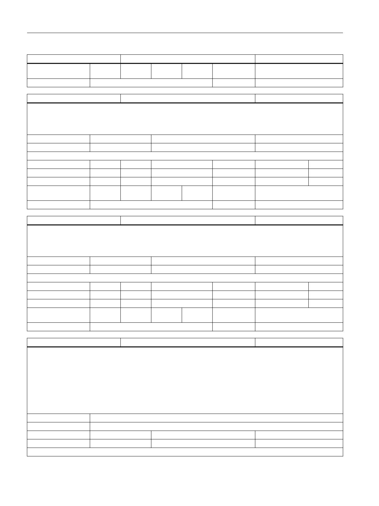
List of system variables
3.2 Channel-specific system variables
$P_SUB_AUTOGEAR
Automatic gear stage change active
BOOL
Axis entry:
Overlap chan-
channel-specific
nel:
Scan mode:
Program sensitive
Link:
No restrictions
$P_SUB_LA
Leading spindle of active coupling
AXIS
Description:
In the substitution subprogram of an NC language substitution configured with $MA_AXIS_LANG_SUB_MASK, this variable supplies the axis
identifier of the leading spindle of the active coupling which initiated the substitution process.
Outside the substitution process, the variable aborts program execution and triggers an alarm.
Unit
Init value
Min
Max
-
GEOAXISNUM
Read/Write properties:
TP
SA
TP/SA safety
NC-Variable
Safety
OEM-CC
Read:
X
-
7
-
0
-
Write:
-
-
0
-
0
-
Axis entry:
Overlap chan-
channel-specific
nel:
Scan mode:
Program sensitive
Link:
No restrictions
$P_SUB_CA
Following spindle of active coupling
AXIS
Description:
In the substitution subprogram of an NC language substitution configured with $MA_AXIS_LANG_SUB_MASK, this variable supplies the axis
identifier of the following spindle of the active coupling which initiated the substitution process.
Outside the substitution process, the variable aborts program execution and triggers an alarm.
Unit
Init value
Min
Max
-
GEOAXISNUM
Read/Write properties:
TP
SA
TP/SA safety
NC-Variable
Safety
OEM-CC
Read:
X
-
7
-
0
-
Write:
-
-
0
-
0
-
Axis entry:
Overlap chan-
channel-specific
nel:
Scan mode:
Program sensitive
Link:
No restrictions
$P_BLOCKNO [INMAXFILESTACK]
Modal block number level-specific
STRING
Description:
$P_BLOCKNO[n]
Supplies the last programmed block number of program level n.
Example:
$P_BLOCKNO[0]
Supplies the modal block number of the program on program level 0 = main program name.
MD 10284 $MN_DISPLAY_FUNCTION_MASK Bit0 must be = 1.
Block numbers programmed during DISPLOF cannot be read with $P_BLOCKNO.
Index 1:
n: Specifies the program level from which the block number is to be read. Numerical value: 0 to 11
Index 3:
Max. string length
Unit
Init value
Min
Max
-
""
Read/Write properties:
System variables
162
List Manual, 10/2020, 6FC5397-6AP40-6BA4
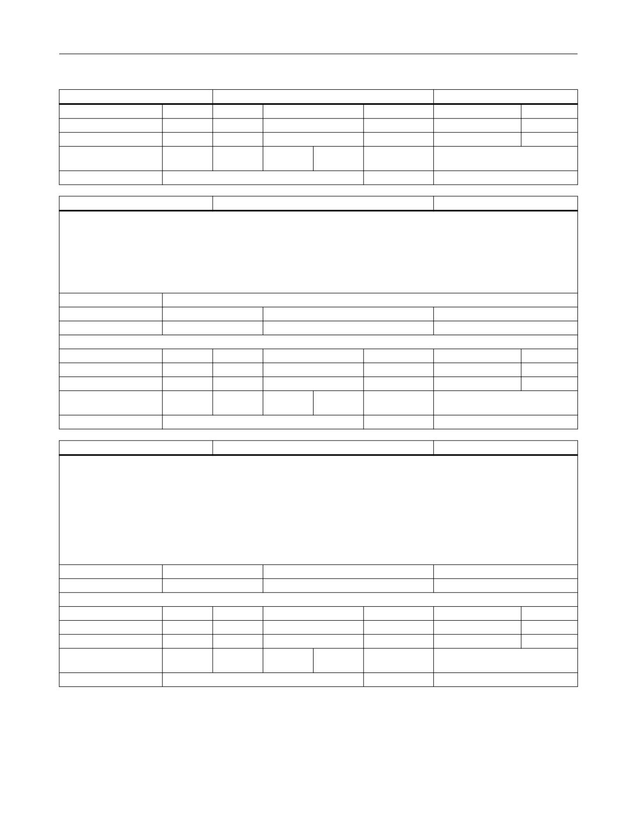
List of system variables
3.2 Channel-specific system variables
$P_BLOCKNO [INMAXFILESTACK]
Modal block number level-specific
STRING
TP
SA
TP/SA safety
NC-Variable
Safety
OEM-CC
Read:
X
-
7
X
7
-
Write:
-
-
0
-
0
-
Axis entry:
Overlap chan-
channel-specific
nel:
Scan mode:
Not classified
Link:
Not classified
$P_LINENO [INMAXFILESTACK]
Line number level-specific
INT
Description:
$P_LINENO[n]
Supplies the last programmed line number of program level n.
Example:
$P_LINENO[0]
Supplies the line number of the program on program level 0 = main program level.
Index 1:
n: Specifies the program level from which the line number is to be read. Numerical value: 0 to 11
Unit
Init value
Min
Max
-
0
-2147483648
2147483647
Read/Write properties:
TP
SA
TP/SA safety
NC-Variable
Safety
OEM-CC
Read:
X
-
7
X
7
-
Write:
-
-
0
-
0
-
Axis entry:
Overlap chan-
channel-specific
nel:
Scan mode:
Not classified
Link:
Not classified
$AC_AUTO_JOG_STATE
Status Jog in Auto
INT
Description:
1: Automatic is selected, $MN_JOG_MODE_MASK is set and the mode group is "BAG-Reset".
By actuating the +/- buttons or the handwheel, you can jog in Auto mode.
2: After a JOG movement has been performed, this mode group was switched by the system to JOG.
The VDI and OPI still display Automatic mode.
0:
Other
Remark: This information covers the whole mode group and is available to each mode group channel
via $AC_AUTO_JOG_STATE.
Unit
Init value
Min
Max
-
0
0
2
Read/Write properties:
TP
SA
TP/SA safety
NC-Variable
Safety
OEM-CC
Read:
-
X
0
X
7
X
Write:
-
-
0
-
0
-
Axis entry:
Overlap chan-
channel-specific
nel:
Scan mode:
Not classified
Link:
Not classified
System variables
List Manual, 10/2020, 6FC5397-6AP40-6BA4
163
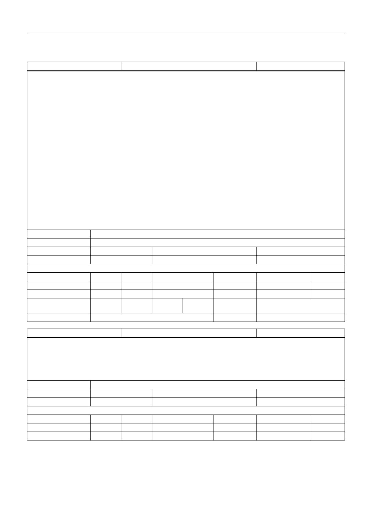
List of system variables
3.2 Channel-specific system variables
$AC_FIFO [n,m]
FIFO stack
DOUBLE
Description:
Variable $AC_FIFO[n,m] access the n-th. first in first out stack. See also $AC_FIFO1 .. $AC_FIFO10.
$MC_NUM_AC_FIFO is used to define the range of n values and thus the number of FIFO Stacks $AC_FIFO1 - $AC_FIFO10.
The elements of the stack memory are saved in R variables. The length of all FIFO stacks is configured with $MC_LEN_AC_FIFO.
$MC_START_AC_FIFO is used to specify the number of the start R variable, from which the FIFO elements are stored.
R variables assigned to FIFO areas should not be written elsewhere.
The number of R variables must be set in machine data $MC_MM_NUM_R_PARAM such that all FIFO variables can be stored:
$MC_MM_NUM_R_PARAM = $MC_MM_START_FIFO + $MC_NUM_AC_FIFO * ($MC_LEN_AC_FIFO + 6)
The FIFO variable is an array variable.
Indices 0 - 5 have special meanings:
m = 0: When written with index 0, a new value is stored in the FIFO.
When read with index 0, the oldest element is read and removed from the FIFO.
m=1: Access to the first element read
m=2: Access to the last element read
m=3: Total of all FIFO elements if Bit0 in $MC_MM_MODE_FIFO is set.
m=4: Number of elements available in the FIFO
m=5: Current write index relative to the start of the FIFO
m=6: Oldest element
m=7: Second oldest etc.
Index 1:
The dimension is configured via $MC_NUM_AC_FIFO.
Index 2:
The dimension is configured via $MC_LEN_AC_FIFO.
Unit
Init value
Min
Max
-
0.0
-1.8E+308
1.8E+308
Read/Write properties:
TP
SA
TP/SA safety
NC-Variable
Safety
OEM-CC
Read:
runin stp
X
7
X
7
X
Write:
X
X
7
-
0
X
Axis entry:
Overlap chan-
channel-specific
nel:
Scan mode:
Not classified
Link:
Not classified
$AC_AUXFU_M_VALUE [168]
Value of active m-auxiliary function
INT
Description:
The array variable $AC_AUXFU_M_VALUE[n] is used to read the value of the M auxiliary function that has been collected last for an auxiliary
function group (search run) or output. Auxiliary functions are assigned to groups. The index corresponds to the group number decremented
by one. The index 0 determines the value of the M auxiliary function output last for the 1st group. If an auxiliary function has not yet been output
for the group specified, the variable returns the value -1. The relevant extension can be determined with the variable $AC_AUXFU_M_EXT[n].
The variable $AC_AUXFU_M_STATE[n] determines the current output status.
Index 1:
The index corresponds to the auxiliary function group number decremented by one.
Unit
Init value
Min
Max
-
0
-2147483648
2147483647
Read/Write properties:
TP
SA
TP/SA safety
NC-Variable
Safety
OEM-CC
Read:
runin stp
X
7
X
7
X
Write:
-
-
0
-
0
-
System variables
164
List Manual, 10/2020, 6FC5397-6AP40-6BA4
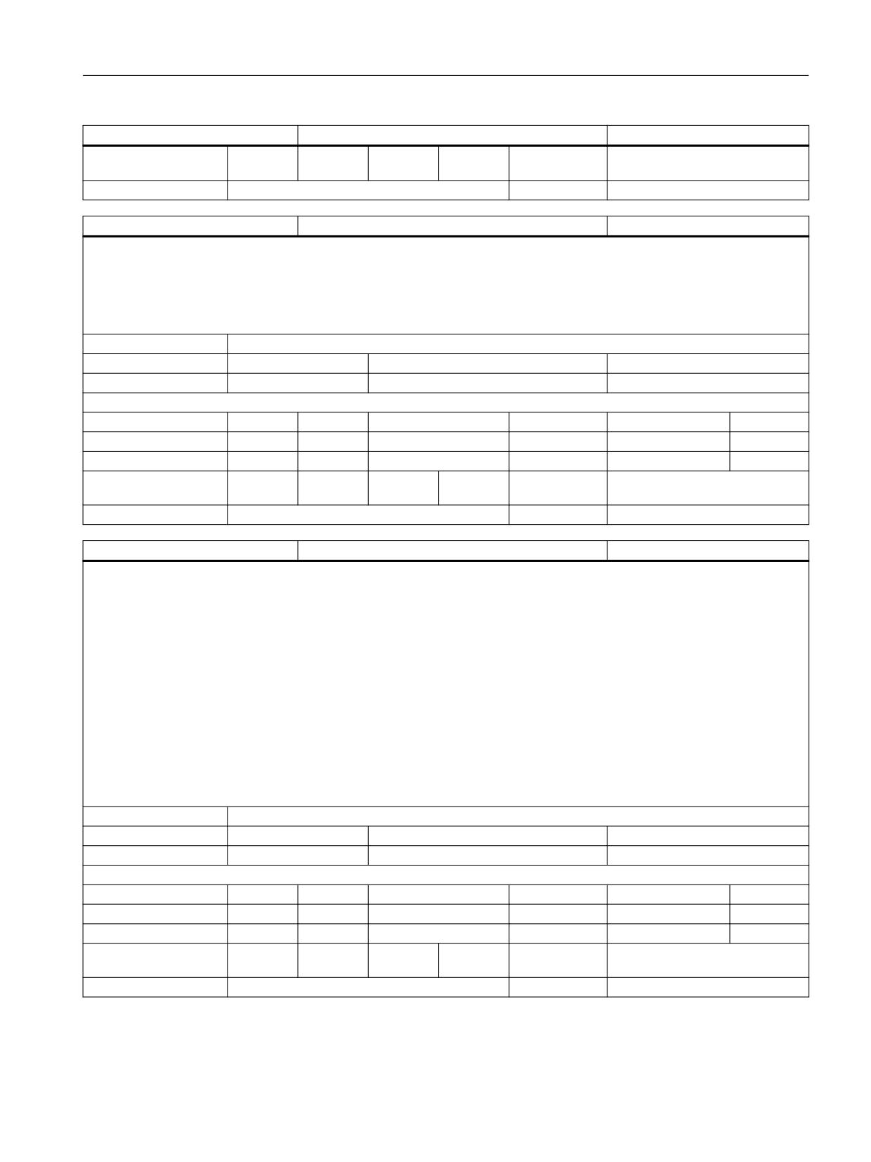
List of system variables
3.2 Channel-specific system variables
$AC_AUXFU_M_VALUE [168]
Value of active m-auxiliary function
INT
Axis entry:
Overlap chan-
channel-specific
nel:
Scan mode:
Not classified
Link:
Not classified
$AC_AUXFU_M_EXT [168]
Extension of active m-auxiliary function
INT
Description:
The array variable $AC_AUXFU_M_EXT[n] is used to read the extension of the M auxiliary function that has been collected last for an auxiliary
function group (search run) or output. Auxiliary functions are assigned to groups. The index corresponds to the group number decremented
by one. The index 0 determines the extension of the M auxiliary function output last for the 1st group. If an auxiliary function has not yet been
output for the group specified, the variable returns the value -1. The relevant value of the auxiliary function can be determined with the variable
$AC_AUXFU_M_VALUE[n]. The variable $AC_AUXFU_M_STATE[n] determines the current output status.
Index 1:
The index corresponds to the auxiliary function group number decremented by one.
Unit
Init value
Min
Max
-
0
-2147483648
2147483647
Read/Write properties:
TP
SA
TP/SA safety
NC-Variable
Safety
OEM-CC
Read:
runin stp
X
7
X
7
X
Write:
-
-
0
-
0
-
Axis entry:
Overlap chan-
channel-specific
nel:
Scan mode:
Not classified
Link:
Not classified
$AC_AUXFU_M_STATE [168]
Output state of axtive m-auxiliary function
INT
Description:
The array variable $AC_AUXFU_M_STATE[n] is used to read the output status of the M auxiliary function that has been collected last for an
auxiliary function group (search run) or output. Auxiliary functions are assigned to groups. The index corresponds to the group number
decremented by one. The index 0 determines the status of the M auxiliary function output last for the 1st group. If an auxiliary function has
not yet been output for the group specified, the variable returns the value 0. If the value is greater than 0, the relevant auxiliary function value
can be determined with the variable $AC_AUXFU_M_VALUE[n]. The variable $AC_AUXFU_M_EXT[n] determines the current extension of the
auxiliary function.
The variable returns the following values:
0: Auxiliary function not available
1: M-auxiliary function collected via search run
2: M-auxiliary function output to the PLC
3: M-auxiliary function output to the PLC, transfer has been acknowledged.
4: M-auxiliary function managed by the PLC and integrated into the PLC.
5: M-auxiliary function managed by the PLC, function has been acknowledged.
Index 1:
The index corresponds to the auxiliary function group number decremented by one.
Unit
Init value
Min
Max
-
0
0
5
Read/Write properties:
TP
SA
TP/SA safety
NC-Variable
Safety
OEM-CC
Read:
runin stp
X
7
X
7
X
Write:
-
-
0
-
0
-
Axis entry:
Overlap chan-
channel-specific
nel:
Scan mode:
Not classified
Link:
Not classified
System variables
List Manual, 10/2020, 6FC5397-6AP40-6BA4
165
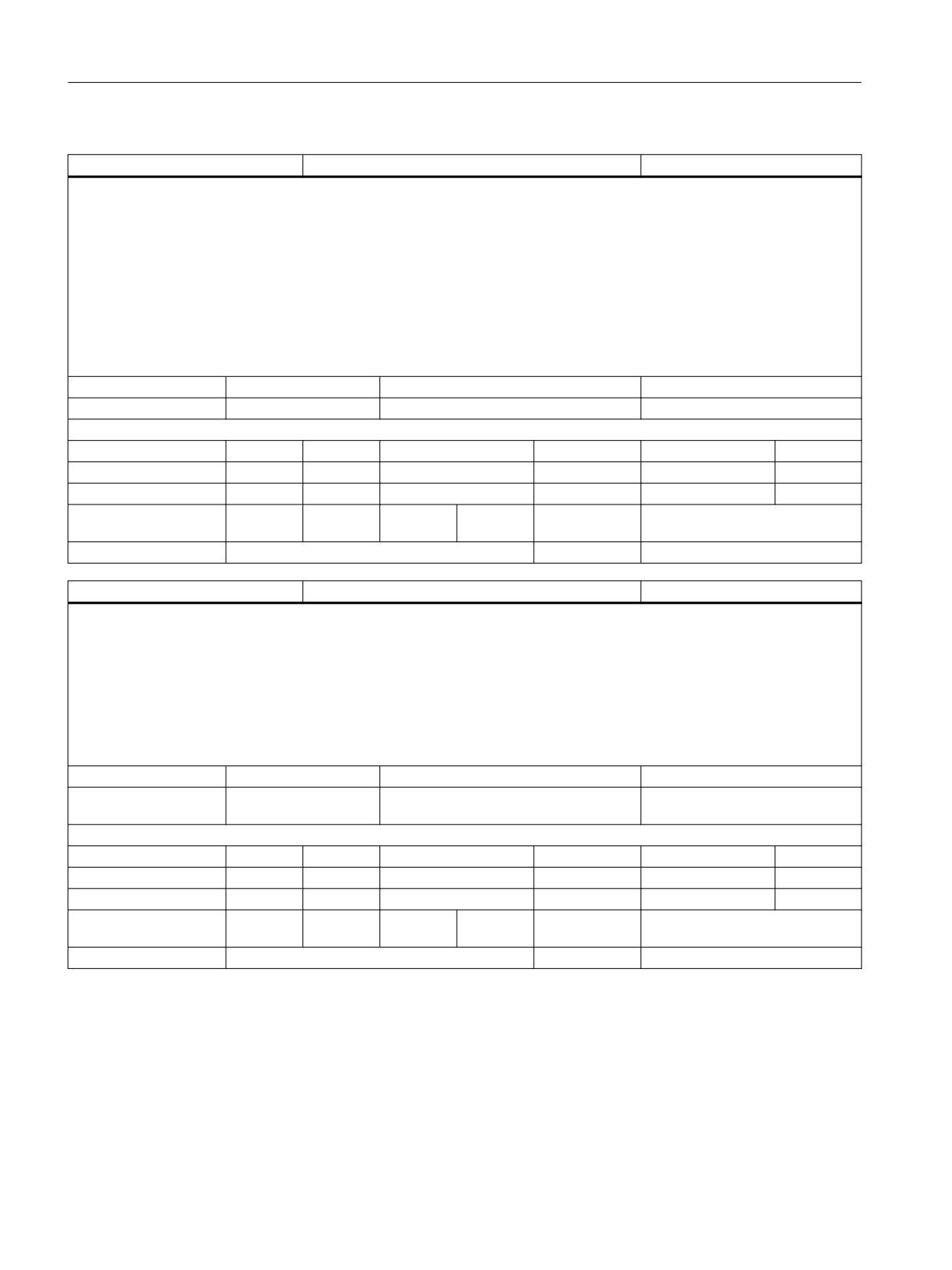
List of system variables
3.2 Channel-specific system variables
$P_THREAD_PITCH
programmed thread pitch
DOUBLE
Description:
$P_THREAD_PITCH provides the lead with G33, G34, G35, G331 and G332 programmed under the address I, J or K. Value 0 is supplied in the
RESET state or if no lead has been programmed. With G33, G34 and G35 a positive value is always returned. With G331 and G332, the sign
results from the spindle rotation direction: positive in clockwise direction (as with M3) or negative in counterclokckwise direction (as with M4).
In the following example, $P_THREAD_PITCH provides the value "1.5".
N11 M4 S500
N12 G33 Z10 K1.4
N13 G33 Z12 K1.5
N14 R1=$P_THREAD_PITCH ;R1=1.5
Unit
Init value
Min
Max
THREAD_PITCH
0.0
-1.8E+308
1.8E+308
Read/Write properties:
TP
SA
TP/SA safety
NC-Variable
Safety
OEM-CC
Read:
X
-
7
-
0
-
Write:
-
-
0
-
0
-
Axis entry:
Overlap chan-
channel-specific
nel:
Scan mode:
Not classified
Link:
Not classified
$P_THREAD_PITCH_INC
programmed thread pitch increment
DOUBLE
Description:
$P_THREAD_PITCH_INC supplies the value programmed under the address F for the lead change (G34/G35). Value 0 is supplied in the RESET
state or if no lead change has been programmed.
The returned value is positive in the case of G34 or negative in the case of G35.
Example:
M3 S400
G35 F2 Z10 K5
R1=$P_THREAD_PITCH_INC ;R1= -2
Unit
Init value
Min
Max
THREAD_PITCH_INCRE-
0.0
-1.8E+308
1.8E+308
MENT
Read/Write properties:
TP
SA
TP/SA safety
NC-Variable
Safety
OEM-CC
Read:
X
-
7
-
0
-
Write:
-
-
0
-
0
-
Axis entry:
Overlap chan-
channel-specific
nel:
Scan mode:
Not classified
Link:
Not classified
System variables
166
List Manual, 10/2020, 6FC5397-6AP40-6BA4
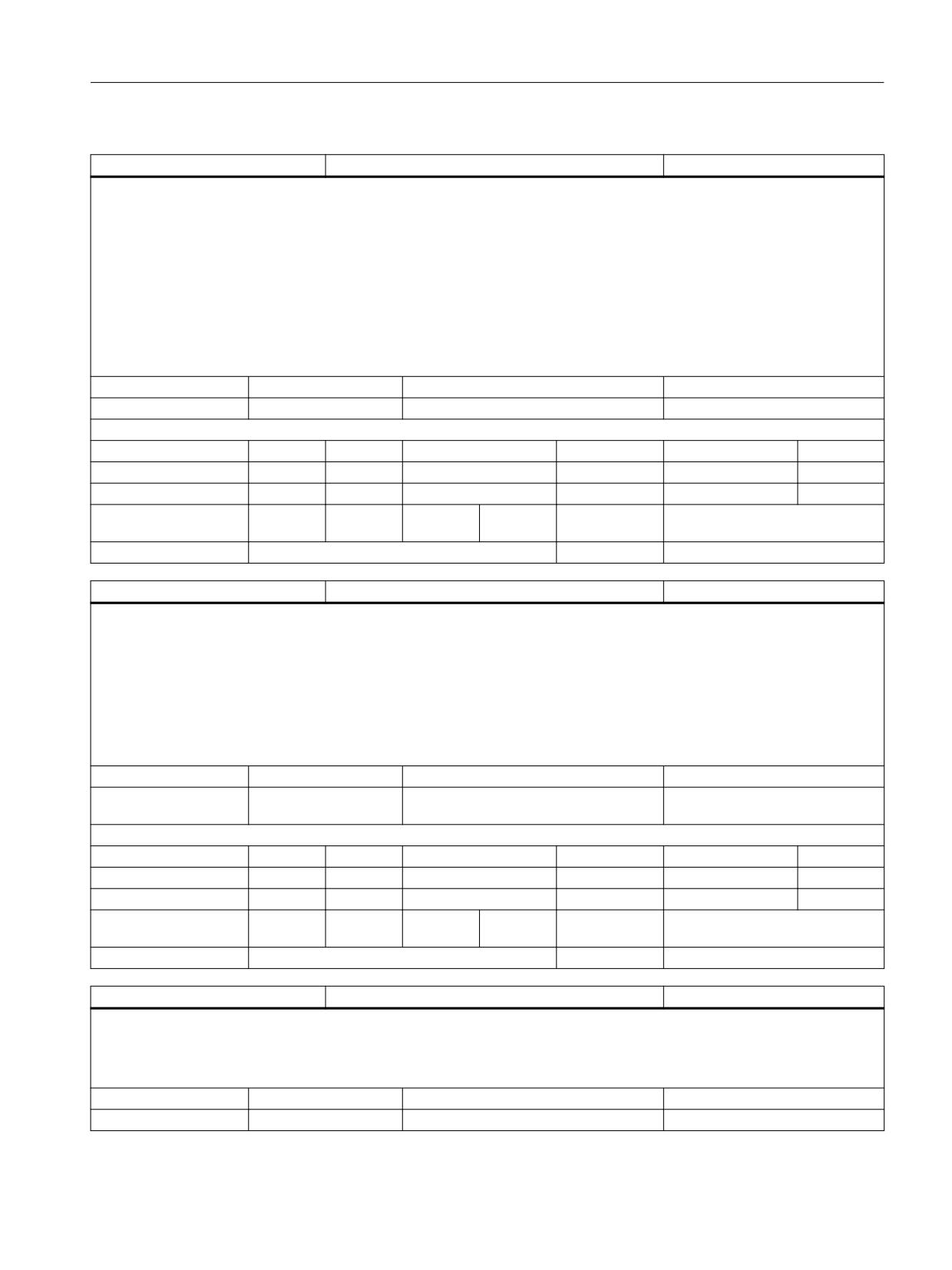
List of system variables
3.2 Channel-specific system variables
$AC_THREAD_PITCH
programmed thread pitch
DOUBLE
Description:
$AC_THREAD_PITCH provides the lead for G33, G34, G35, G331 and G332 programmed under address I, J or K. In the RESET state or if no lead
has been programmed, the value 0 is given. With G33, G34 and G35, a positive value is always returned. With G331 and G332, the sign from
the spindle rotating direction is as follows: positive for clockwise rotation (as with M3) or negative for counterclockwise rotation (as with M4).
In the following example, $AC_THREAD_PITCH provides the value "1.5" :
N11 M4 S500
N12 G33 Z10 K1.4
N13 G33 Z12 K1.5
N14 R1=$AC_THREAD_PITCH ;R1= 1.5
Unit
Init value
Min
Max
THREAD_PITCH
0.0
-1.8E+308
1.8E+308
Read/Write properties:
TP
SA
TP/SA safety
NC-Variable
Safety
OEM-CC
Read:
runin stp
X
7
X
7
X
Write:
-
-
0
-
0
-
Axis entry:
Overlap chan-
channel-specific
nel:
Scan mode:
Not classified
Link:
Not classified
$AC_THREAD_PITCH_INC
current thread pitch increment
DOUBLE
Description:
$AC_THREAD_PITCH_INC provides the value programmed under the address F for lead change (G34/G35). In the RESET state or if a change in
lead has not been programmed, the value 0 is supplied.
The returned value is positive for G34 and negative for G35.
Example:
M3 S400
G34 F4 Z10 K2
R1=$P_THREAD_PITCH_INC ;R1= 4
Unit
Init value
Min
Max
THREAD_PITCH_INCRE-
0.0
-1.8E+308
1.8E+308
MENT
Read/Write properties:
TP
SA
TP/SA safety
NC-Variable
Safety
OEM-CC
Read:
runin stp
X
7
X
7
X
Write:
-
-
0
-
0
-
Axis entry:
Overlap chan-
channel-specific
nel:
Scan mode:
Not classified
Link:
Not classified
$AC_THREAD_PITCH_ACT
current thread pitch just now
DOUBLE
Description:
$AC_THREAD_PITCH_ACT provides the current value for the lead. This value is continuously updated in blocks with G34 or G35 according to
the value programmed under F.
Only with thread blocks (G33, G34, G35, G331 and G332) a value unequal zero is supplied.
Unit
Init value
Min
Max
THREAD_PITCH
0.0
-1.8E+308
1.8E+308
System variables
List Manual, 10/2020, 6FC5397-6AP40-6BA4
167
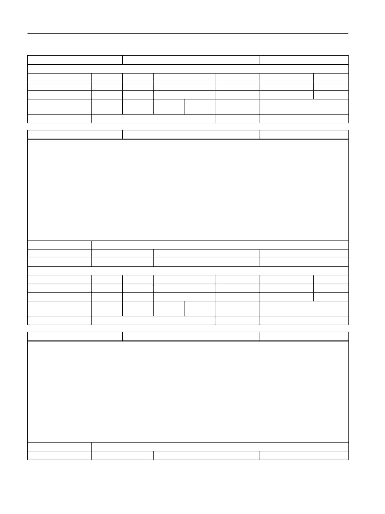
List of system variables
3.2 Channel-specific system variables
$AC_THREAD_PITCH_ACT
current thread pitch just now
DOUBLE
Read/Write properties:
TP
SA
TP/SA safety
NC-Variable
Safety
OEM-CC
Read:
runin stp
X
7
X
7
X
Write:
-
-
0
-
0
-
Axis entry:
Overlap chan-
channel-specific
nel:
Scan mode:
Not classified
Link:
Not classified
$P_TOOLROT [3]
Programmed tool rotation direction
DOUBLE
Description:
$P_TOOLROTn]
Programmed tool rotation vector
Normalized vector with length 1 and the components
(n = 1, 2, 3) in the range - 1, ..., 1.
1: x-component
2: y-component
3: z-component
If no tool is active, the following unit vector is returned, depending on the active plane:
G17: (0, 1, 0)
G18: (1, 0, 0)
G19: (0, 0, 1)
Index 1:
n: Components 1 - 3
Unit
Init value
Min
Max
-
0.0
-1.0
1.0
Read/Write properties:
TP
SA
TP/SA safety
NC-Variable
Safety
OEM-CC
Read:
X
-
7
-
0
-
Write:
-
-
0
-
0
-
Axis entry:
Overlap chan-
channel-specific
nel:
Scan mode:
Not classified
Link:
No restrictions
$AC_TOOLR_ACT [3]
Active tool rotation direction
DOUBLE
Description:
$AC_TOOLR_ACT[n]
Active command rotation vector
Normalized vector with length 1 and the components
(n = 1, 2, 3) in the range - 1, ..., 1.
1: x-component
2: y-component
3: z-component
If no tool is active, the following unit vector is returned, depending on the active plane:
G17: (0, 1, 0)
G18: (1, 0, 0)
G19: (0, 0, 1)
Index 1:
n: Components 1 - 3
Unit
Init value
Min
Max
System variables
168
List Manual, 10/2020, 6FC5397-6AP40-6BA4
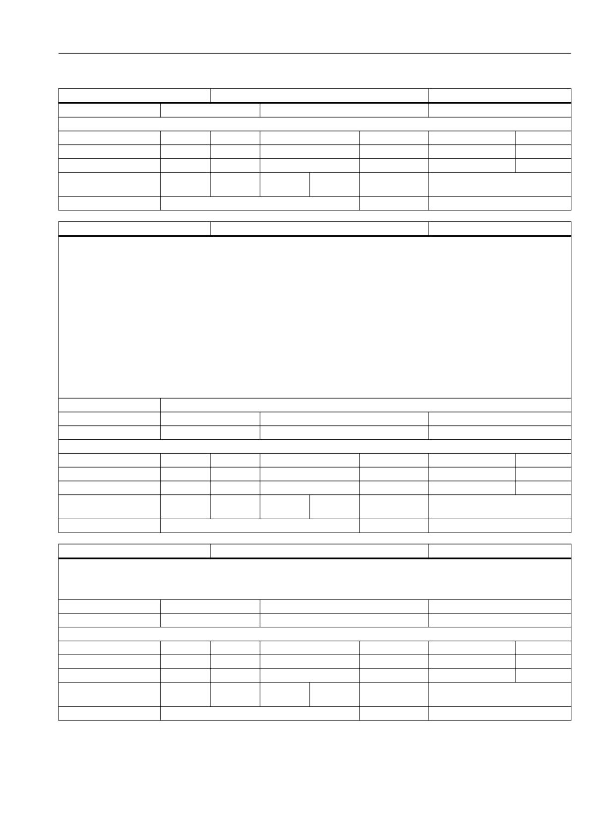
List of system variables
3.2 Channel-specific system variables
$AC_TOOLR_ACT [3]
Active tool rotation direction
DOUBLE
-
0.0
-1.0
1.0
Read/Write properties:
TP
SA
TP/SA safety
NC-Variable
Safety
OEM-CC
Read:
runin stp
X
7
X
7
X
Write:
-
-
0
-
0
-
Axis entry:
Overlap chan-
channel-specific
nel:
Scan mode:
Not classified
Link:
No restrictions
$AC_TOOLR_END [3]
End rotation direction vector
DOUBLE
Description:
$AC_TOOLR_END[n]
End rotation vector of active block
Normalized vector with length 1 and the components
(n = 1, 2, 3) in the range - 1, ..., 1.
1: x-component
2: y-component
3: z-component
If no tool is active, the following unit vector is returned, depending on the active plane:
G17: (0, 1, 0)
G18: (1, 0, 0)
G19: (0, 0, 1)
Index 1:
n: Components 1 - 3
Unit
Init value
Min
Max
-
0.0
-1.0
1.0
Read/Write properties:
TP
SA
TP/SA safety
NC-Variable
Safety
OEM-CC
Read:
runin stp
X
7
X
7
X
Write:
-
-
0
-
0
-
Axis entry:
Overlap chan-
channel-specific
nel:
Scan mode:
Not classified
Link:
No restrictions
$AC_TOOLR_DIFF
Remaining angle of the tool rotation direction
DOUBLE
Description:
$AC_TOOLR_DIFF
Remaining angle of tool rotation in active block in degree in the range 0 ... 180 degree.
Unit
Init value
Min
Max
deg.
0.0
0.0
180.0
Read/Write properties:
TP
SA
TP/SA safety
NC-Variable
Safety
OEM-CC
Read:
runin stp
X
7
X
7
X
Write:
-
-
0
-
0
-
Axis entry:
Overlap chan-
channel-specific
nel:
Scan mode:
Not classified
Link:
No restrictions
System variables
List Manual, 10/2020, 6FC5397-6AP40-6BA4
169
List of system variables
3.2 Channel-specific system variables
$VC_TOOLR [3]
Actual rotation direction vector
DOUBLE
Description:
$VC_TOOLR[n]
Actual tool rotation
Normalized vector with length 1 and the components
(n = 1, 2, 3) in the range - 1, ..., 1.
1: x-component
2: y-component
3: z-component
If no tool is active, the following unit vector is returned, depending on the active plane:
G17: (0, 1, 0)
G18: (1, 0, 0)
G19: (0, 0, 1)
Index 1:
n: Components 1 - 3
Unit
Init value
Min
Max
-
0.0
-1.0
1.0
Read/Write properties:
TP
SA
TP/SA safety
NC-Variable
Safety
OEM-CC
Read:
runin stp
X
7
X
7
X
Write:
-
-
0
-
0
-
Axis entry:
Overlap chan-
channel-specific
nel:
Scan mode:
Not classified
Link:
No restrictions
$VC_TOOLR_DIFF
Angle between set and actual rotation
DOUBLE
Description:
$VC_TOOLR_DIFF
Angle between command and actual tool rotation in degree in the range 0 ... 180 degree.
Unit
Init value
Min
Max
deg.
0.0
0.0
180.0
Read/Write properties:
TP
SA
TP/SA safety
NC-Variable
Safety
OEM-CC
Read:
runin stp
X
7
X
7
X
Write:
-
-
0
-
0
-
Axis entry:
Overlap chan-
channel-specific
nel:
Scan mode:
Not classified
Link:
No restrictions
$VC_TOOLR_STAT
Status of actual rotation direction vector
INT
Description:
$VC_TOOLR_STAT
Status of calculation of actual tool rotation:
0: MCS -> BCS Transformation in one ipo cycle
-1: MCS -> BCS transformation not in one ipo cycle possible
Unit
Init value
Min
Max
-
0
-1
0
Read/Write properties:
System variables
170
List Manual, 10/2020, 6FC5397-6AP40-6BA4
List of system variables
3.2 Channel-specific system variables
$VC_TOOLR_STAT
Status of actual rotation direction vector
INT
TP
SA
TP/SA safety
NC-Variable
Safety
OEM-CC
Read:
runin stp
X
7
X
7
X
Write:
-
-
0
-
0
-
Axis entry:
Overlap chan-
channel-specific
nel:
Scan mode:
Not classified
Link:
No restrictions
$P_SIMUL
Simulation search run active
BOOL
Description:
Value==TRUE
The part program is executed in the control under the Simulation search run mode.
The simulation search run is a search run (with calculation)
which is aborted with an
internal M30 once the end of the program has been reached.
The control is internally in search run mode, the variables $P_SEARCH,
$P_SERACH1, $P_SEARCH2 and $P_SERACHL are also correctly supplied.
Parts program adjustments can be made through variables
$P_SEARCH* or $P_SIMUL. $P_SIMUL is designed only for adjustments
restricted to the simulation search run.
Value==FALSE No simulation search run is active.
Unit
Init value
Min
Max
-
FALSE
FALSE
TRUE
Read/Write properties:
TP
SA
TP/SA safety
NC-Variable
Safety
OEM-CC
Read:
X
-
7
-
0
-
Write:
-
-
0
-
0
-
Axis entry:
Overlap chan-
channel-specific
nel:
Scan mode:
Current value
Link:
Not classified
$P_SUB_STAT
state of substitution subroutine
INT
Description:
A replacement of the tool programming has been configured (address D, DL, T or M function through which the tool change cycle is called up).
$P_SUB_STAT now permits polling to see if the substitution process is active and if the process is executed at the start or the end of the block:
Value 0: Substitution subprogram not active
Value 1: Substitution subprogram active,
call-up at start of block
Value 2: Substitution subprogram active,
call-up at end of block
The system variable is influenced by machine data
$MN_T_NO_FCT_CYCLE_MODE bit1 and 2.
Unit
Init value
Min
Max
-
0
0
2
Read/Write properties:
TP
SA
TP/SA safety
NC-Variable
Safety
OEM-CC
Read:
X
-
7
-
0
-
Write:
-
-
0
-
0
-
System variables
List Manual, 10/2020, 6FC5397-6AP40-6BA4
171
List of system variables
3.2 Channel-specific system variables
$P_SUB_STAT
state of substitution subroutine
INT
Axis entry:
Overlap chan-
channel-specific
nel:
Scan mode:
Program sensitive
Link:
No restrictions
$A_USEDND [128]
Workpiece counts for cutting edges
INT
Description:
$A_USEDND[ toolHolder ]
The number of cutting edges used in tool holder s, counted since the last setpiece command, including the currently active cutting edge.
toolHolder=1,...,maximum tool holder number
toolHolder=0 = The master tool holder is selected
Result = >0 = Number of cutting edges that have been used.
Result = 0 = There have been no cuts since the last setpiece command.
Result = -1 = Tool Management Tool Monitoring is not active.
Result = -2 = toolHolder is not the value of a defined tool holder.
Index 1:
toolHolder: Spindle number/tool holder number
Unit
Init value
Min
Max
-
0
0
2147483647
Read/Write properties:
TP
SA
TP/SA safety
NC-Variable
Safety
OEM-CC
Read:
runin stp
X
7
X
7
X
Write:
-
-
0
-
0
-
Axis entry:
Overlap chan-
channel-specific
nel:
Scan mode:
Not classified
Link:
Not classified
$A_USEDT [128,3000]
Workpiece counts for cutting edges
INT
Description:
$A_USEDT[ toolHolder, usedCuttingEdgeIndex ]
T number of the i-th tool, of the cutting edges that have been used or are still being used on the tool holder s since the last workpiece count.
toolHolder=1,...,maximum tool holder number
toolHolder=0 = Designates the master tool holder
usedCuttingEdgeIndex= 1 - $A_USEDND[ toolHolder ]
Result = >0 = T number (can occur several times) (if different D offsets of the tool were used).
Result = 0 = No more cutting edges used since the last workpiece count.
Result = -1 = Tool monitoring function is not active.
Result = -2 = toolHolder is the value of an undefined tool holder.
Index 1:
toolHolder: Spindle number/tool holder number
Index 2:
usedCuttingEdgeIndex: index (1 - $A_USEDND[ toolHolder ] )
Unit
Init value
Min
Max
-
0
0
2147483647
Read/Write properties:
TP
SA
TP/SA safety
NC-Variable
Safety
OEM-CC
Read:
runin stp
X
7
X
7
X
Write:
-
-
0
-
0
-
Axis entry:
Overlap chan-
channel-specific
nel:
Scan mode:
Not classified
Link:
Not classified
System variables
172
List Manual, 10/2020, 6FC5397-6AP40-6BA4
List of system variables
3.2 Channel-specific system variables
$A_USEDD [128,3000]
Workpiece counts for cutting edges
INT
Description:
$A_USEDD[ toolHolder, usedCuttingEdgeIndex ]
D number of the i-th tool, of the cutting edges that have been used or are still being used on the tool holder s since the last workpiece count.
toolHolder=1,...,maximum tool holder number
toolHolder=0 = Designates the master tool holder
usedCuttingEdgeIndex = 1 - $A_USEDND[ toolHolder ]
Result = >0 = D number (can occur several times) (if different D offsets of the tool were used).
Result = 0 = No more cutting edges used since the last workpiece count.
Result = -1 = Tool monitoring function is not active.
Result = -2 = toolHolder is the value of an undefined tool holder.
Index 1:
toolHolder: Spindle number/tool holder number
Index 2:
usedCuttingEdgeIndex: index ( 1 - $A_USEDND[ toolHolder ] )
Unit
Init value
Min
Max
-
0
0
2147483647
Read/Write properties:
TP
SA
TP/SA safety
NC-Variable
Safety
OEM-CC
Read:
runin stp
X
7
X
7
X
Write:
-
-
0
-
0
-
Axis entry:
Overlap chan-
channel-specific
nel:
Scan mode:
Not classified
Link:
Not classified
$AC_AUXFU_M_TICK [168]
Time stamp of active M auxiliary function
INT
Description:
Field variable $AC_AUXFU_M_TICK[n] is used to read the time stamp of the M auxiliary function collected (search run) or output last for an
auxiliary function group. Auxiliary functions are assigned to groups. The index corresponds to a group number decremented by one. Index 0
therefore determines the value of the M auxiliary function of the 1st group, which was output last. If no auxiliary function has been output for
the specific group, the variable indicates value -1. The respective value can be determined using variable $AC_AUXFU_M_VALUE[n] and the
respective extension using variable $AC_AUXFU_M_EXT[n]. Variable $AC_AUXFU_M_STATE[n] determines the current output state.
Index 1:
The index corresponds to the auxiliary function group number decremented by one.
Unit
Init value
Min
Max
-
0
-2147483648
2147483647
Read/Write properties:
TP
SA
TP/SA safety
NC-Variable
Safety
OEM-CC
Read:
runin stp
X
7
-
0
X
Write:
-
-
0
-
0
-
Axis entry:
Overlap chan-
channel-specific
nel:
Scan mode:
Not classified
Link:
Not classified
$AC_CONE_ANGLE
Cone angle
DOUBLE
Description:
$AC_CONE_ANGLE
Currently active cone angle for cone turning. The cone angle is set by default via the setting data $SC_CONE_ANGLE and is active in JOG mode
only.
Unit
Init value
Min
Max
deg.
0.0
-90
90
System variables
List Manual, 10/2020, 6FC5397-6AP40-6BA4
173
List of system variables
3.2 Channel-specific system variables
$AC_CONE_ANGLE
Cone angle
DOUBLE
Read/Write properties:
TP
SA
TP/SA safety
NC-Variable
Safety
OEM-CC
Read:
runin stp
X
7
X
7
-
Write:
-
-
0
-
0
-
Axis entry:
Overlap chan-
channel-specific
nel:
Scan mode:
Not classified
Link:
Not classified
$P_TECCYCLE
Context query in technology cycles
BOOL
Description:
To control the context-specific interpretation of program parts in technology cycles, preprocessing variable $P_TECCYCLE is available. Using this
variable, programs can be subdivided into synchronized action program parts and preprocessing program parts.
Example:
if ($P_TECCYCLE == TRUE)
; Program sequence for a technology cycle in synchronized action
else
; Program sequence for parts program cycle
endif
Unit
Init value
Min
Max
-
FALSE
FALSE
TRUE
Read/Write properties:
TP
SA
TP/SA safety
NC-Variable
Safety
OEM-CC
Read:
X
-
7
-
0
-
Write:
-
-
0
-
0
-
Axis entry:
Overlap chan-
channel-specific
nel:
Scan mode:
Not classified
Link:
Not classified
$AC_WORKAREA_CS_PLUS_ENABLE
Active coord.-specific working area limitation, positive
BOOL
[n]
valid
Description:
TRUE: The limitation in the positive direction for the specified axis in the active coordinate system-specific working area limitation is valid. (s.
$AC_WORKAREA_CS_LIMIT_PLUS[ ax])
Index 1:
Axis name of the working area limitation. Any axis names known in the channel are permitted as axis name.
Unit
Init value
Min
Max
-
FALSE
FALSE
TRUE
Read/Write properties:
TP
SA
TP/SA safety
NC-Variable
Safety
OEM-CC
Read:
runin stp
X
7
X
7
X
Write:
-
-
0
-
0
-
Axis entry:
GEO
CHAN
MACH
Overlap chan-
channel-specific
nel:
Scan mode:
Not classified
Link:
No restrictions
System variables
174
List Manual, 10/2020, 6FC5397-6AP40-6BA4
List of system variables
3.2 Channel-specific system variables
$AC_WORKAREA_CS_MINUS_ENABLE
Active coord.-specific working area limitation, negative
BOOL
[n]
valid
Description:
TRUE: The limitation in the negative direction for the specified axis in the active coordinate system-specific working area limitation is valid. (s.
$AC_WORKAREA_CS_LIMIT_MINUS[ ax])
Index 1:
Axis name of the working area limitation. Any axis names known in the channel are permitted as axis name.
Unit
Init value
Min
Max
-
FALSE
FALSE
TRUE
Read/Write properties:
TP
SA
TP/SA safety
NC-Variable
Safety
OEM-CC
Read:
runin stp
X
7
X
7
X
Write:
-
-
0
-
0
-
Axis entry:
GEO
CHAN
MACH
Overlap chan-
channel-specific
nel:
Scan mode:
Not classified
Link:
No restrictions
$AC_WORKAREA_CS_LIMIT_PLUS [n]
Coordinate system-specific working area limitation pos-
DOUBLE
itive
Description:
The limitation in the positive direction for the specified axis in the active coordinate system-specific working area limitation. This value is only
evaluated, if $AC_WORKAREA_CS_PLUS_ENABLE = TRUE.
Index 1:
Axis name of the working area limitation. Any axis names known in the channel are permitted as axis name.
Unit
Init value
Min
Max
Linear / angular position
0.0
-1.8E+308
1.8E+308
Read/Write properties:
TP
SA
TP/SA safety
NC-Variable
Safety
OEM-CC
Read:
runin stp
X
7
X
7
X
Write:
-
-
0
-
0
-
Axis entry:
GEO
CHAN
MACH
Overlap chan-
channel-specific
nel:
Scan mode:
Not classified
Link:
No restrictions
$AC_WORKAREA_CS_LIMIT_MINUS
Coordinate system-specific working area limitation neg-
DOUBLE
[n]
ative
Description:
The limitation in the negative direction for the specified axis in the active coordinate system-specific working area limitation. This value is only
evaluated, if $AC_WORKAREA_CS_MINUS_ENABLE = TRUE.
Index 1:
Axis name of the working area limitation. Any axis names known in the channel are permitted as axis name.
Unit
Init value
Min
Max
Linear / angular position
0.0
-1.8E+308
1.8E+308
Read/Write properties:
TP
SA
TP/SA safety
NC-Variable
Safety
OEM-CC
Read:
runin stp
X
7
X
7
X
Write:
-
-
0
-
0
-
Axis entry:
GEO
CHAN
MACH
Overlap chan-
channel-specific
nel:
Scan mode:
Not classified
Link:
No restrictions
System variables
List Manual, 10/2020, 6FC5397-6AP40-6BA4
175
List of system variables
3.2 Channel-specific system variables
$AC_WORKAREA_CS_COORD_SYS-
Coordinate system applies to the active working area
INT
TEM
limitation
Description:
Coordinate system in which the active, coordinate-specific working area limitation applies.
The following values apply:
Working area limitation applies in the WCS
Working area limitation applies in the SZS
Unit
Init value
Min
Max
-
0
0
2147483647
Read/Write properties:
TP
SA
TP/SA safety
NC-Variable
Safety
OEM-CC
Read:
runin stp
X
7
X
7
X
Write:
-
-
0
-
0
-
Axis entry:
Overlap chan-
channel-specific
nel:
Scan mode:
Not classified
Link:
No restrictions
$AC_WORKAREA_CS_GROUP
Group no. of the active, coord.-specific working area
INT
limitation
Description:
Number of the active group of the coordinate system-specific working area limitation. The value is determined in the NC program by the G code
WALCS0-WALCS10.
Unit
Init value
Min
Max
-
0
0
2147483647
Read/Write properties:
TP
SA
TP/SA safety
NC-Variable
Safety
OEM-CC
Read:
runin stp
X
7
X
7
X
Write:
-
-
0
X
7
-
Axis entry:
Overlap chan-
channel-specific
nel:
Scan mode:
Not classified
Link:
No restrictions
$P_ISO1FRAME
Active system frame for ISO G51.1 mirroring
FRAME
Description:
Variable $P_ISO1FRAME is used to program the active system frame for ISO G51.1 mirroring.
On a Reset, the activation of the system frame depends on the following machine data:
Bit0 in $MC_RESET_MODE_MASK
Bit7 in $MC_CHSFRAME_RESET_MASK
Unit
Init value
Min
Max
-
Read/Write properties:
TP
SA
TP/SA safety
NC-Variable
Safety
OEM-CC
Read:
X
-
7
X
7
-
Write:
X
-
7
-
0
-
Axis entry:
GEO
CHAN
MACH
SPIN
Overlap chan-
channel-specific
nel:
Scan mode:
Not classified
Link:
No restrictions
System variables
176
List Manual, 10/2020, 6FC5397-6AP40-6BA4
List of system variables
3.2 Channel-specific system variables
$P_ISO2FRAME
Active system frame for ISO G68 2DROT
FRAME
Description:
The variable $P_ISO2FRAME is used to program the active system frame for ISO G68 2DROT.
On a Reset, the activation of the system frame depends on the following machine data:
Bit0 in $MC_RESET_MODE_MASK
Bit8 in $MC_CHSFRAME_RESET_MASK
Unit
Init value
Min
Max
-
Read/Write properties:
TP
SA
TP/SA safety
NC-Variable
Safety
OEM-CC
Read:
X
-
7
X
7
-
Write:
X
-
7
-
0
-
Axis entry:
GEO
CHAN
MACH
SPIN
Overlap chan-
channel-specific
nel:
Scan mode:
Not classified
Link:
No restrictions
$P_ISO3FRAME
Active system frame for ISO G68 3DROT
FRAME
Description:
The variable $P_ISO3FRAME is used to program the active system frame for ISO G68 3DROT.
On a Reset, the activation of the system frame depends on the following machine data:
Bit0 in $MC_RESET_MODE_MASK
Bit9 in $MC_CHSFRAME_RESET_MASK
Unit
Init value
Min
Max
-
Read/Write properties:
TP
SA
TP/SA safety
NC-Variable
Safety
OEM-CC
Read:
X
-
7
X
7
-
Write:
X
-
7
-
0
-
Axis entry:
GEO
CHAN
MACH
SPIN
Overlap chan-
channel-specific
nel:
Scan mode:
Not classified
Link:
No restrictions
$P_ISO4FRAME
Active system frame for ISO G51 Scale
FRAME
Description:
The variable $P_ISO4FRAME is used to program the active system frame for ISO G51 Scale.
On a Reset, the activation of the system frame depends on the following machine data:
Bit0 in $MC_RESET_MODE_MASK
Bit10 in $MC_CHSFRAME_RESET_MASK
Unit
Init value
Min
Max
-
Read/Write properties:
TP
SA
TP/SA safety
NC-Variable
Safety
OEM-CC
Read:
X
-
7
X
7
-
Write:
X
-
7
-
0
-
Axis entry:
GEO
CHAN
MACH
SPIN
Overlap chan-
channel-specific
nel:
Scan mode:
Not classified
Link:
No restrictions
System variables
List Manual, 10/2020, 6FC5397-6AP40-6BA4
177
List of system variables
3.2 Channel-specific system variables
$P_ACSFRAME
Active frame between BCS and SZS
FRAME
Description:
The variable $P_ACSFRAME determines the active chained total frame between BCS and SZS.
The following applies to $MC_FRAME_ACS_SET = 0:
$P_ACSFRAME = $P_PARTFRAME : $P_SETFRAME : $P_EXTFRAME : $P_ISO1FRAME : $P_ISO2FRAME : $P_ISO3FRAME : $P_ACTBFRAME :
$P_IFRAME : $P_GFRAME : $P_TOOLFRAME : $P_WPFRAME
The following applies to $MC_FRAME_ACS_SET = 1:
$P_ACSFRAME = $P_PARTFRAME : $P_SETFRAME : $P_EXTFRAME : $P_ISO1FRAME : $P_ISO2FRAME : $P_ISO3FRAME : $P_ACTBFRAME :
$P_IFRAME : $P_GFRAME : $P_TOOLFRAME : $P_WPFRAME : $P_TRAFRAME : $P_PFRAME : $P_ISO4FRAME
Unit
Init value
Min
Max
-
Read/Write properties:
TP
SA
TP/SA safety
NC-Variable
Safety
OEM-CC
Read:
X
-
7
X
7
-
Write:
-
-
0
-
0
-
Axis entry:
GEO
CHAN
MACH
SPIN
Overlap chan-
channel-specific
nel:
Scan mode:
Not classified
Link:
No restrictions
$P_CUT_INV
Invert direction of spindle rotation
BOOL
Description:
$P_CUT_INV
This system variable is used to indicate whether or not the direction of spindle rotation has to be inverted for machining with the currently active
tool.
The variable has the value TRUE if the four following conditions are fulfilled:
1. A turning tool is active (tool types 500 to 599).
2. The cutting edge influencing has been activated with the language command CUTMOD = 1 or CUTMOD =2.
3. A tool carrier with orientation capability is active.
4. The tool carrier with orientation capability rotates the tool so that the resulting normal of the tool cutting edge to the initial position is rotated
more than 90 degrees (typically 180 degrees).
The content of the variable is FALSE if at least one of the four conditions has not been fulfilled.
Unit
Init value
Min
Max
-
FALSE
FALSE
TRUE
Read/Write properties:
TP
SA
TP/SA safety
NC-Variable
Safety
OEM-CC
Read:
X
-
7
X
7
-
Write:
-
-
0
-
0
-
Axis entry:
Overlap chan-
channel-specific
nel:
Scan mode:
Not classified
Link:
No restrictions
System variables
178
List Manual, 10/2020, 6FC5397-6AP40-6BA4
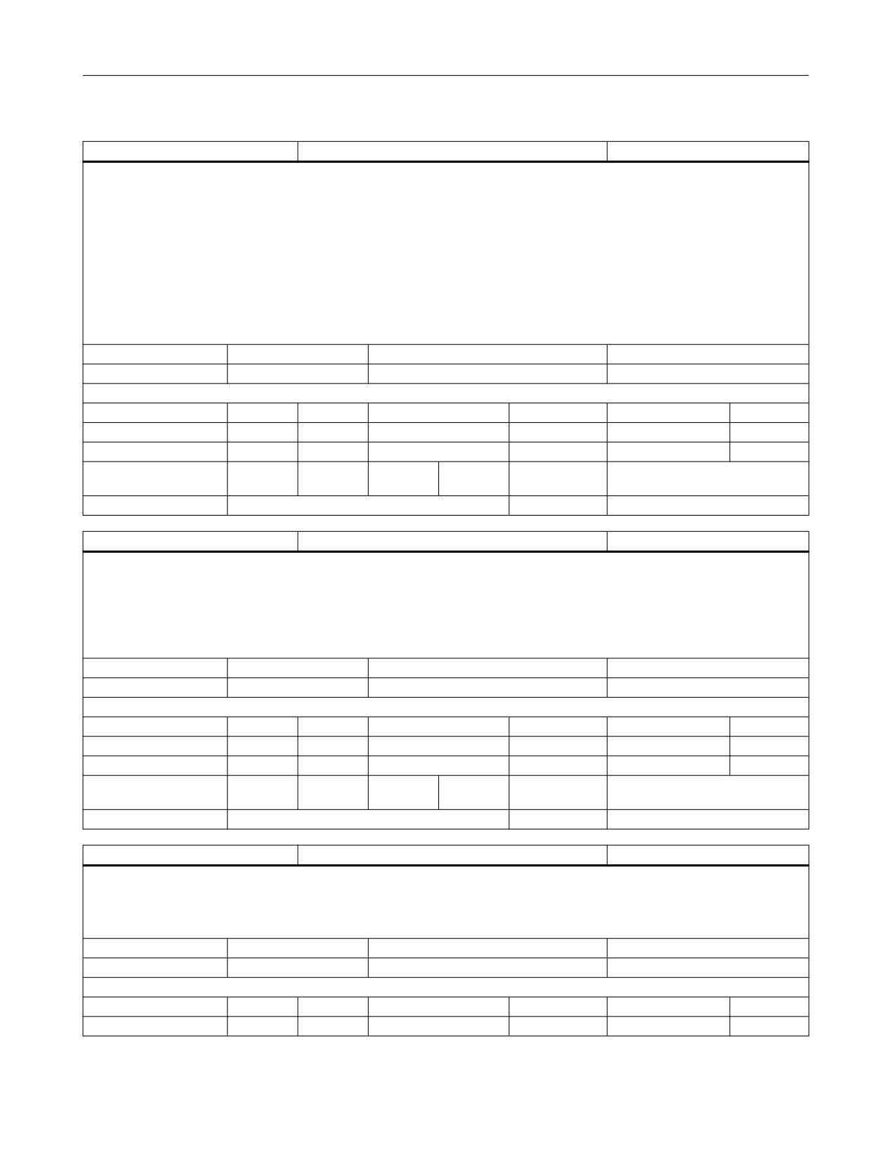
List of system variables
3.2 Channel-specific system variables
$AC_CUT_INV
Invert direction of spindle rotation
BOOL
Description:
This system variable $AC_CUT_INV is used to indicate whether or not the direction of spindle rotation has to be inverted for machining with the
currently active tool.
The variable has the value TRUE if the four following conditions are fulfilled:
1. A turning tool is active (tool types 500 to 599).
2. The cutting edge influencing has been activated with the language command CUTMOD = 1 or CUTMOD =2.
3. A tool carrier with orientation capability is active.
4. The tool carrier with orientation capability rotates the tool so that the resulting normal of the tool cutting edge to the initial position is rotated
more than 90 degrees (typically 180 degrees).
The content of the variable is FALSE if at least one of the four conditions has not been fulfilled.
Unit
Init value
Min
Max
-
FALSE
FALSE
TRUE
Read/Write properties:
TP
SA
TP/SA safety
NC-Variable
Safety
OEM-CC
Read:
runin stp
X
7
X
7
X
Write:
-
-
0
-
0
-
Axis entry:
Overlap chan-
channel-specific
nel:
Scan mode:
Not classified
Link:
No restrictions
$P_CUTMOD
The last programmed value of CUTMOD
INT
Description:
$P_CUTMOD
Reads the current valid value that was last programmed with the language command CUTMOD (number of the tool carrier for which the cutting
edge data modification is to be activated).
If the last programmed value was CUTMOD = -2 (activation with the currently active tool carrier with orientation capability), $P_CUTMOD does
not return the value -2 but the number of the active tool carrier with orientation capability at the time of programming.
Unit
Init value
Min
Max
-
0
-2
2147483647
Read/Write properties:
TP
SA
TP/SA safety
NC-Variable
Safety
OEM-CC
Read:
X
-
7
X
7
-
Write:
-
-
0
-
0
-
Axis entry:
Overlap chan-
channel-specific
nel:
Scan mode:
Not classified
Link:
No restrictions
$AC_CUTMOD
The value of CUTMOD in the current block.
INT
Description:
$AC_CUTMOD
Reads the currently valid value of the language command CUTMOD in the current block (number of the tool carrier for which the cutting edge
data modification is to be activated).
Unit
Init value
Min
Max
-
0
-2
2147483647
Read/Write properties:
TP
SA
TP/SA safety
NC-Variable
Safety
OEM-CC
Read:
runin stp
X
7
X
7
X
System variables
List Manual, 10/2020, 6FC5397-6AP40-6BA4
179
List of system variables
3.2 Channel-specific system variables
$AC_CUTMOD
The value of CUTMOD in the current block.
INT
Write:
-
-
0
-
0
-
Axis entry:
Overlap chan-
channel-specific
nel:
Scan mode:
Not classified
Link:
No restrictions
$P_CUTMOD_ANG
Tool rotation angle in the active machining plane
DOUBLE
Description:
The variable $P_CUTMOD_ANG reads the angle through which a tool has been rotated in the active machining plane, and on which the
determination of modified cutting edge data with the functions CUTMOD and/or $SC_CUTDIRMOD is based.
Unit
Init value
Min
Max
deg.
0.0
-360
360
Read/Write properties:
TP
SA
TP/SA safety
NC-Variable
Safety
OEM-CC
Read:
X
-
7
X
7
-
Write:
-
-
0
-
0
-
Axis entry:
Overlap chan-
channel-specific
nel:
Scan mode:
Not classified
Link:
No restrictions
$AC_CUTMOD_ANG
Tool rotation angle in the active machining plane
DOUBLE
Description:
The variable $AC_CUTMOD_ANG determines the angle through which a tool has been rotated in the active machining plane and on which the
determination of modified cutting edge data for the functions CUTMOD and/or $SC_CUTDIRMOD is based.
Unit
Init value
Min
Max
deg.
0.0
-360
360
Read/Write properties:
TP
SA
TP/SA safety
NC-Variable
Safety
OEM-CC
Read:
runin stp
X
7
X
7
X
Write:
-
-
0
-
0
-
Axis entry:
Overlap chan-
channel-specific
nel:
Scan mode:
Not classified
Link:
No restrictions
$P_SUB_SPOS
Language substitution for SPOS command active
BOOL
Description:
Returns an NC language substitution TRUE (1) configured with $MA_AXIS_LANG_SUB_MASK bit1 = 1 in the substitution subprogram if the
substitution was activated by the SPOS command.
Unit
Init value
Min
Max
-
FALSE
FALSE
TRUE
Read/Write properties:
TP
SA
TP/SA safety
NC-Variable
Safety
OEM-CC
Read:
X
-
7
-
0
-
Write:
-
-
0
-
0
-
Axis entry:
Overlap chan-
channel-specific
nel:
Scan mode:
Program sensitive
Link:
No restrictions
System variables
180
List Manual, 10/2020, 6FC5397-6AP40-6BA4
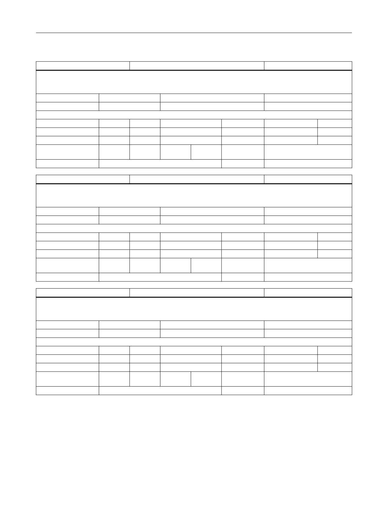
List of system variables
3.2 Channel-specific system variables
$P_SUB_SPOSA
Language substitution for SPOSA command active
BOOL
Description:
Returns an NC language substitution TRUE (1) configured with $MA_AXIS_LANG_SUB_MASK bit1 = 1 in the substitution subprogram if the
substitution was activated by the SPOSA command.
Unit
Init value
Min
Max
-
FALSE
FALSE
TRUE
Read/Write properties:
TP
SA
TP/SA safety
NC-Variable
Safety
OEM-CC
Read:
X
-
7
-
0
-
Write:
-
-
0
-
0
-
Axis entry:
Overlap chan-
channel-specific
nel:
Scan mode:
Program sensitive
Link:
No restrictions
$P_SUB_M19
Language substitution M19 active.
BOOL
Description:
Returns an NC language substitution TRUE (1) configured with $MA_AXIS_LANG_SUB_MASK bit1 = 1 in the substitution subprogram if the
substitution was activated by M19.
Unit
Init value
Min
Max
-
FALSE
FALSE
TRUE
Read/Write properties:
TP
SA
TP/SA safety
NC-Variable
Safety
OEM-CC
Read:
X
-
7
-
0
-
Write:
-
-
0
-
0
-
Axis entry:
Overlap chan-
channel-specific
nel:
Scan mode:
Program sensitive
Link:
No restrictions
$P_SUB_SPOSIT
SPOS/SPOSA position with language substitution
DOUBLE
Description:
Returns the programmed position of an NC language substitution configured with $MA_AXIS_LANG_SUB_MASK bit1 = 1 in the substitution
subprogram. If the variable is called outside this substitution process, the program execution is canceled with alarm 14055.
Unit
Init value
Min
Max
-
0.0
-1.8E+308
1.8E+308
Read/Write properties:
TP
SA
TP/SA safety
NC-Variable
Safety
OEM-CC
Read:
X
-
7
-
0
-
Write:
-
-
0
-
0
-
Axis entry:
Overlap chan-
channel-specific
nel:
Scan mode:
Program sensitive
Link:
No restrictions
System variables
List Manual, 10/2020, 6FC5397-6AP40-6BA4
181
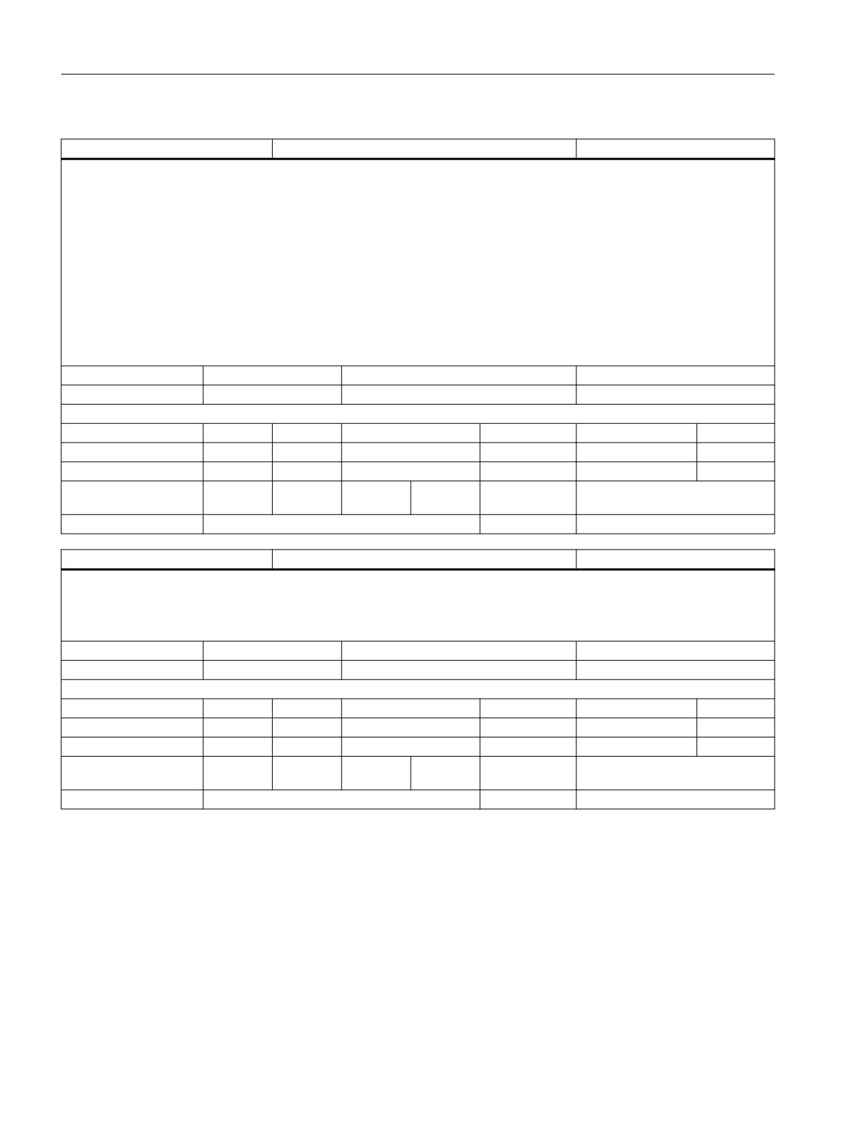
List of system variables
3.2 Channel-specific system variables
$P_SUB_SPOSMODE
Position approach mode with language substitution
INT
Description:
The variable $P_SUB_SPOSMODE determines, with a language substitution:
$MA_AXIS_LANG_SUB_MASK bit1 = 1
configured in the substitution subprogram, the position approach mode for the spindle position returned by $P_SUB_SPOSIT.
0: DC
1: AC
2: IC
3: DC
4: ACP
5: ACN
If the variable is called outside this substitution process, the program execution is canceled with alarm 14055.
Unit
Init value
Min
Max
-
0
0
5
Read/Write properties:
TP
SA
TP/SA safety
NC-Variable
Safety
OEM-CC
Read:
X
-
7
-
0
-
Write:
-
-
0
-
0
-
Axis entry:
Overlap chan-
channel-specific
nel:
Scan mode:
Program sensitive
Link:
No restrictions
$AC_SAFE_SYNA_MEM
Free safety synchronized action elements
INT
Description:
The variable $AC_SAFE_SYNA_MEM determines the number of free synchronized action elements for Safety Integrated. The maximum number
of elements is configured by $MC_MM_NUM_SAFE_SYNC_ELEMENTS.
The value is read from the part program without a preprocessing stop.
Unit
Init value
Min
Max
-
0
0
2147483647
Read/Write properties:
TP
SA
TP/SA safety
NC-Variable
Safety
OEM-CC
Read:
runin stp
X
7
X
7
X
Write:
-
-
0
-
0
-
Axis entry:
Overlap chan-
channel-specific
nel:
Scan mode:
Not classified
Link:
Not classified
System variables
182
List Manual, 10/2020, 6FC5397-6AP40-6BA4
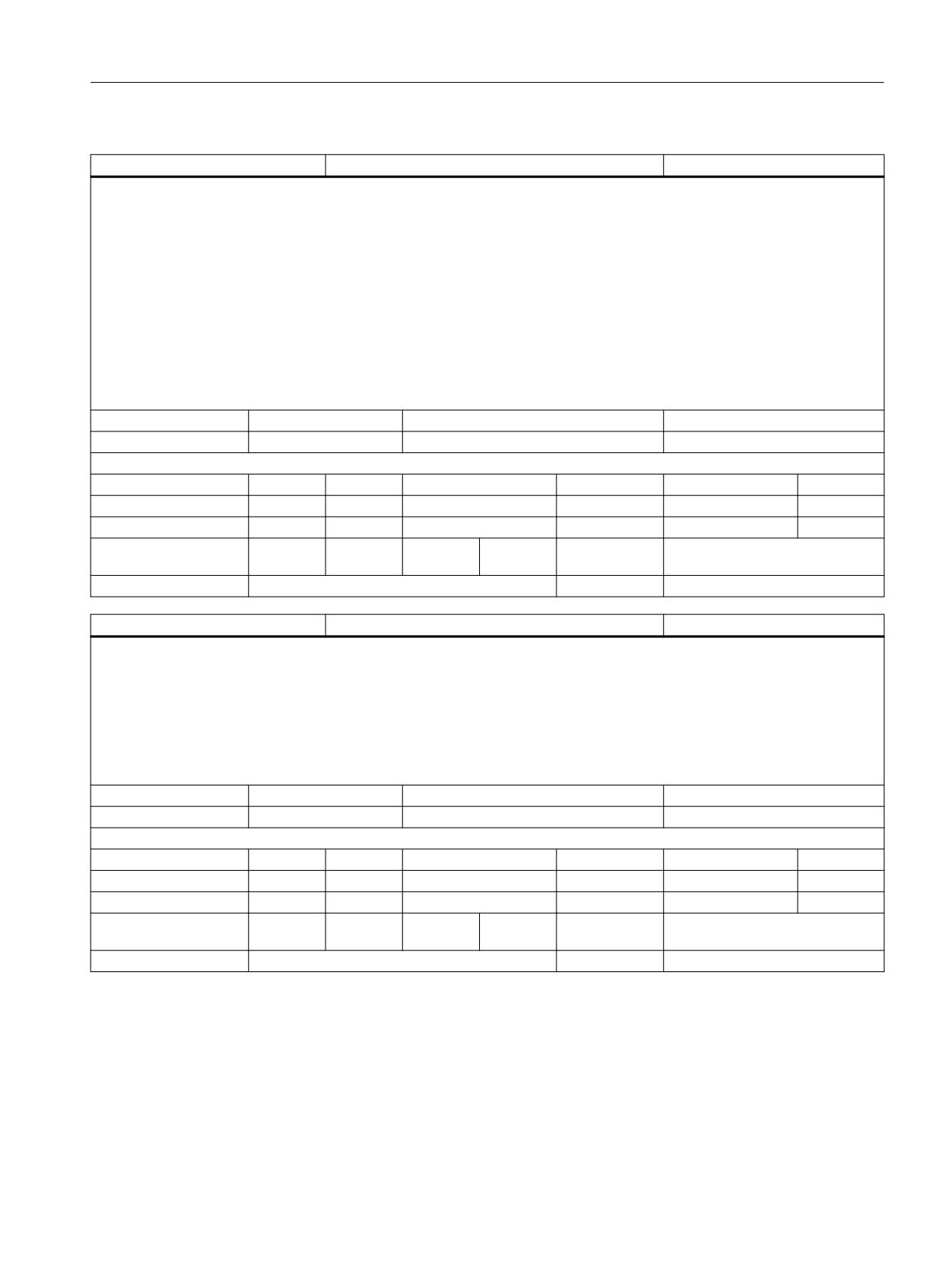
List of system variables
3.2 Channel-specific system variables
$AC_ACT_PROG_NET_TIME
Execution time of the selected NC program
DOUBLE
Description:
The current net runtime of the current program, in other words, the time during which the program was stopped has been deducted. If a part
program is restarted in automatic mode from the channel status RESET, $AC_ACT_PROG_NET_TIME is automatically reset to zero.
$AC_ACT_PROG_NET_TIME is reset to zero when M30 is reached. The net runtime does not include the time during which the program stops
because Override=0.
$AC_ACT_PROG_NET_TIME can be further manipulated with $AC_PROG_NET_TIME_TRIGGER.
Note: The RESET key does not reset $AC_ACT_PROG_NET_TIME to zero, it merely stops $AC_ACT_PROG_NET_TIME. $AC_ACT_PROG_NET_TIME
is not reset by default with GOTOS (except with the 828D). If GOTOS is to behave like program end M30, bit 0 of machine data
$MC_PROG_NET_TIMER_MODE must be set.
When an ASUB is started, $AC_ACT_PROG_NET_TIME is set to zero, and counts the runtime of the ASUB. $AC_ACT_PROG_NET_TIME is not reset
when Prog-Events is started. $AC_ACT_PROG_NET_TIME is additionally increased only with a start event, M30 ProgEvent and search run
ProgEvent. At the end of an ASUB, $AC_ACT_PROG_NET_TIME behaves the same as the RESET button, this means that.
$AC_ACT_PROG_NET_TIME is only stopped, it is not set to 0.
Unit
Init value
Min
Max
s
0.0
0
1.8E+308
Read/Write properties:
TP
SA
TP/SA safety
NC-Variable
Safety
OEM-CC
Read:
runin stp
X
7
X
7
X
Write:
-
-
0
-
0
-
Axis entry:
Overlap chan-
channel-specific
nel:
Scan mode:
Current value
Link:
No restrictions
$AC_OLD_PROG_NET_TIME
Runtime of the last NC program
DOUBLE
Description:
$AC_OLD_PROG_NET_TIME is the net runtime of the program that has just finished correctly, this means that the program was not canceled
with RESET, it was ended normally with M30. If a new program is started, $AC_OLD_PROG_NET_TIME remains unaffected until M30 is reached
again.
The implicit copying process from $AC_ACT_PROG_NET_TIME to $AC_OLD_PROG_NET_TIME takes place only if $AC_PROG_NET_TIME_TRIG-
GER is not written.
Note: $AC_OLD_PROG_NET_TIME is reset to zero by PI "Select program". $AC_OLD_PROG_NET_TIME is set to zero if the currently selected
program is edited. $AC_OLD_PROG_NET_TIME is not changed at the end of an ASUB or a Prog-Event.
Unit
Init value
Min
Max
s
0.0
0
1.8E+308
Read/Write properties:
TP
SA
TP/SA safety
NC-Variable
Safety
OEM-CC
Read:
X
X
7
X
7
X
Write:
-
-
0
X
7
-
Axis entry:
Overlap chan-
channel-specific
nel:
Scan mode:
Current value
Link:
No restrictions
System variables
List Manual, 10/2020, 6FC5397-6AP40-6BA4
183
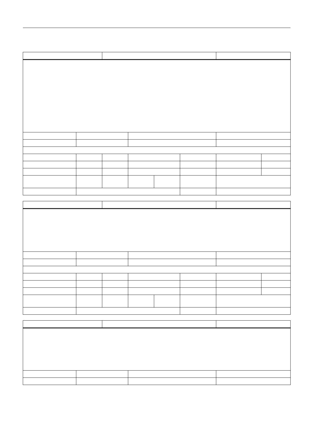
List of system variables
3.2 Channel-specific system variables
$AC_PROG_NET_TIME_TRIGGER
Trigger for runtime measurement
INT
Description:
$AC_PROG_NET_TIME_TRIGGER is used to selectively measure program sections. This means that by writing $AC_PROG_NET_TIME_TRIGGER
the program can switch time measurement on and off.
In order to exploit all trigger possibilities, certain values of $AC_PROG_NET_TIME_TRIGGER are assigned a special function:
0 = Neutral: The trigger is not active, the value is taken from Reset with the start button.
1 = Exit: Exits the measurement and copies $AC_ACT_PROG_NET_TIME to $AC_OLD_PROG_NET_TIME. $AC_ACT_PROG_NET_TIME is set to
zero, and then starts running again.
2 = Start: Starts the measurement and sets $AC_ACT_PROG_NET_TIME to zero. $AC_OLD_PROG_NET_TIME is not changed.
3 = Stop: Stops the measurement, does not change $AC_OLD_PROG_NET_TIME, and holds $AC_ACT_PROG_NET_TIME constant until continue.
4 = Continue: Continuation of the measurement, this means that a measurement that has been stopped is resumed.
$AC_ACT_PROG_NET_TIME continues to run. $AC_OLD_PROG_NET_TIME is not changed.
Unit
Init value
Min
Max
s
0
0
2147483647
Read/Write properties:
TP
SA
TP/SA safety
NC-Variable
Safety
OEM-CC
Read:
runin stp
X
7
X
7
X
Write:
runin stp
X
7
-
0
-
Axis entry:
Overlap chan-
channel-specific
nel:
Scan mode:
Program sensitive
Link:
No restrictions
$AC_OLD_PROG_NET_TIME_COUNT
Change counter for $AC_OLD_PROG_NET_TIME
INT
Description:
$AC_OLD_PROG_NET_TIME_COUNT is zero in the Power ON status. $AC_OLD_PROG_NET_TIME_COUNT is always increased when the NCK has
newly written $AC_OLD_PROG_NET_TIME. This enables the user to ensure that $AC_OLD_PROG_NET_TIME has been written. This means that,
if the user cancels the current program with reset, $AC_OLD_PROG_NET_TIME and $AC_OLD_PROG_NET_TIME_COUNT remain unchanged. As
oldProgNetTime is reset when a new program is selected, in this case oldProgNetTimeCount is also increased.
Note: Two programs running consecutively can have identical runtimes and be correctly terminated. The user can then only detect this by the
changed $AC_OLD_PROG_NET_TIME_COUNT.
Unit
Init value
Min
Max
s
0
0
2147483647
Read/Write properties:
TP
SA
TP/SA safety
NC-Variable
Safety
OEM-CC
Read:
X
X
7
X
7
X
Write:
-
-
0
-
0
-
Axis entry:
Overlap chan-
channel-specific
nel:
Scan mode:
Current value
Link:
No restrictions
$P_OPMODE
Selected mode
INT
Description:
The variable $P_OPMODE determines the mode selected via the PLC.
The variable returns the following values:
0: JOG (manual traverse)
1: MDA (Manual Data Automatic)
2: AUTOMATIC
Unit
Init value
Min
Max
-
0
0
2
System variables
184
List Manual, 10/2020, 6FC5397-6AP40-6BA4
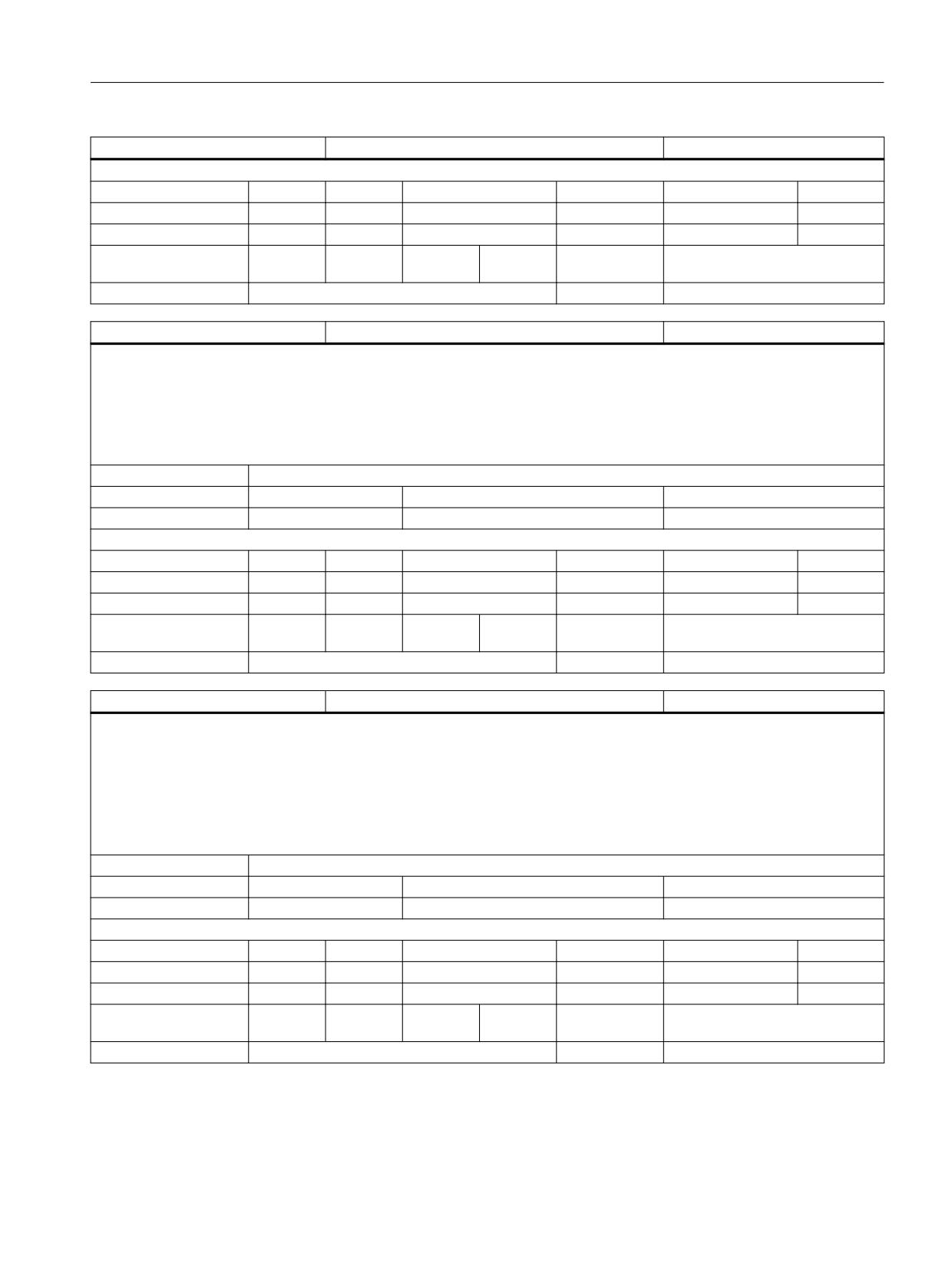
List of system variables
3.2 Channel-specific system variables
$P_OPMODE
Selected mode
INT
Read/Write properties:
TP
SA
TP/SA safety
NC-Variable
Safety
OEM-CC
Read:
X
-
7
-
0
-
Write:
-
-
0
-
0
-
Axis entry:
Overlap chan-
channel-specific
nel:
Scan mode:
Not classified
Link:
Not classified
$P_TOFF [n]
Programmed tool length offset
DOUBLE
Description:
$P_TOFF
Programmed tool length offset.
The variable returns the tool length offset which is assigned to the geometry axis defined as an index.
The system variable returns the offset values assigned to the tool length components irrespective of whether the offsets have been programmed
with TOFFL or TOFF.
Index 1:
Tool length offset of the tool length component in direction of the respective geometry axis with non-rotated tool.
Unit
Init value
Min
Max
mm
0.0
-1.8E+308
1.8E+308
Read/Write properties:
TP
SA
TP/SA safety
NC-Variable
Safety
OEM-CC
Read:
X
-
7
-
0
-
Write:
-
-
0
-
0
-
Axis entry:
GEO
Overlap chan-
channel-specific
nel:
Scan mode:
Not classified
Link:
Not classified
$AC_TOFFL [3]
Programmed tool length offset
DOUBLE
Description:
$AC_TOFFL
Programmed tool length offset.
The variable returns the offset assigned in $AC_TOFFL[1] to the tool length component L1. The same applies to indices 2 and 3.
$AC_TOFFL[0] accesses the offset of the length component L1 in the same way as $AC_TOFFL[1].
The system variable returns the offset values assigned to the tool length components irrespective of whether the offsets have been programmed
with TOFFL or TOFF.
Index 1:
Tool length offset of tool length components L1 (indices 0 or 1), L2 (index 2), or L3 (index 3)
Unit
Init value
Min
Max
mm
0.0
-1.8E+308
1.8E+308
Read/Write properties:
TP
SA
TP/SA safety
NC-Variable
Safety
OEM-CC
Read:
runin stp
X
7
X
7
-
Write:
-
-
0
-
0
-
Axis entry:
Overlap chan-
channel-specific
nel:
Scan mode:
Not classified
Link:
Not classified
System variables
List Manual, 10/2020, 6FC5397-6AP40-6BA4
185
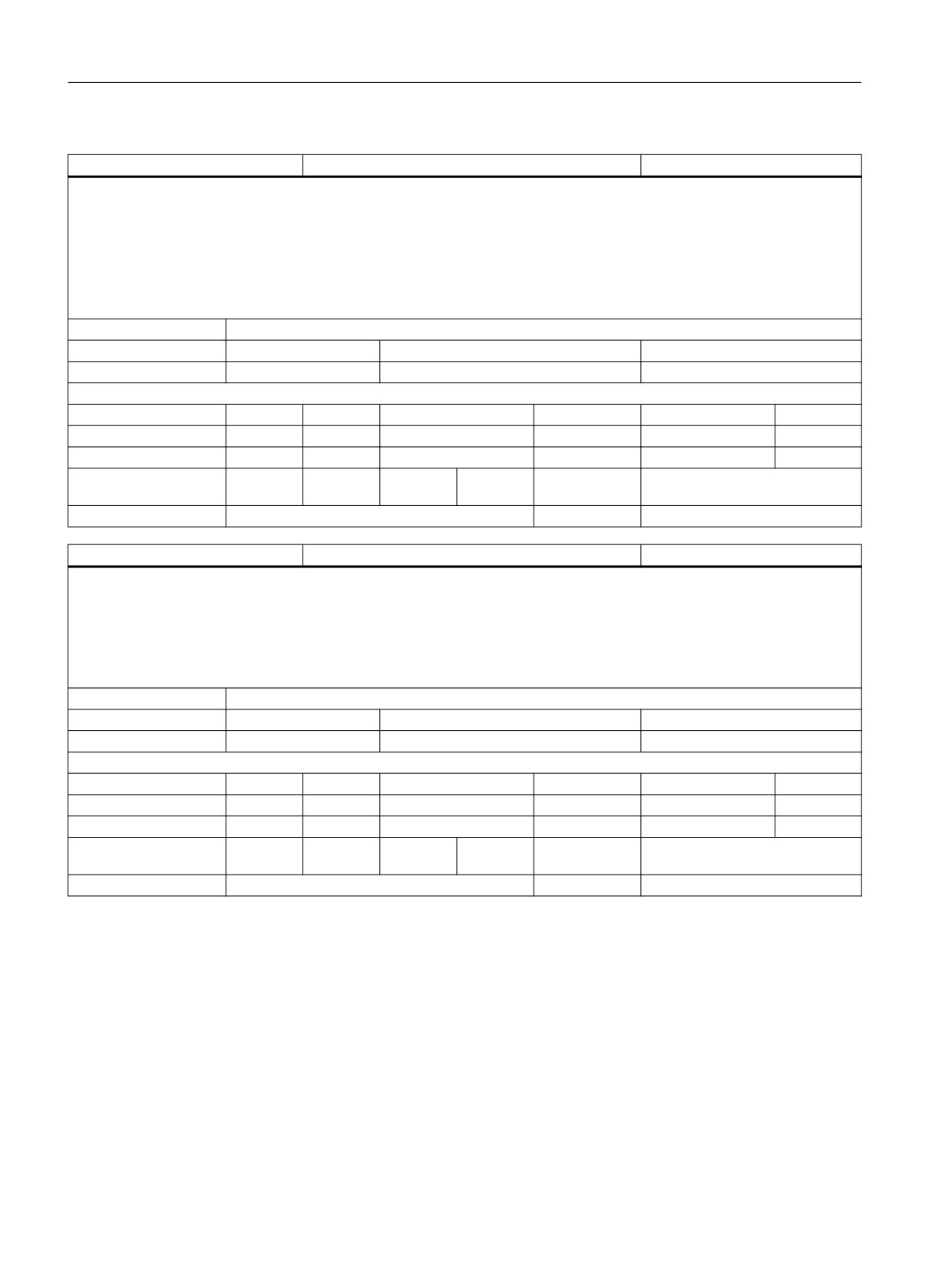
List of system variables
3.2 Channel-specific system variables
$P_TOFFL [3]
Programmed tool length offset
DOUBLE
Description:
$P_TOFFL
Programmed tool length offset.
The variable returns the offset assigned to the tool length component L1 in $P_TOFFL[1]. The same applies to indices 2 and 3.
$P_TOFFL[0] accesses the offset of the length component L1 in the same way as $P_TOFFL[1].
The system variable returns the offset values assigned to the tool length components irrespective of whether the offsets have been programmed
with TOFFL or TOFF.
Index 1:
Tool length offset of tool length components L1 (indices 0 or 1), L2 (index 2), or L3 (index 3)
Unit
Init value
Min
Max
mm
0.0
-1.8E+308
1.8E+308
Read/Write properties:
TP
SA
TP/SA safety
NC-Variable
Safety
OEM-CC
Read:
X
-
7
-
0
-
Write:
-
-
0
-
0
-
Axis entry:
Overlap chan-
channel-specific
nel:
Scan mode:
Not classified
Link:
Not classified
$AC_TOFF [n]
Programmed tool length offset
DOUBLE
Description:
$AC_TOFF
Programmed tool length offset.
The variable returns the tool length offset which is assigned to the geometry axis defined as an index.
The system variable returns the offset values assigned to the tool length components irrespective of whether the offsets have been programmed
with TOFFL or TOFF.
Index 1:
Tool length offset of the tool length component in direction of the respective geometry axis with non-rotated tool.
Unit
Init value
Min
Max
mm
0.0
-1.8E+308
1.8E+308
Read/Write properties:
TP
SA
TP/SA safety
NC-Variable
Safety
OEM-CC
Read:
runin stp
X
7
X
7
-
Write:
-
-
0
-
0
-
Axis entry:
GEO
Overlap chan-
channel-specific
nel:
Scan mode:
Not classified
Link:
Not classified
System variables
186
List Manual, 10/2020, 6FC5397-6AP40-6BA4
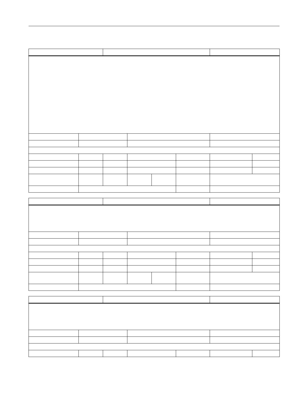
List of system variables
3.2 Channel-specific system variables
$AC_JOG_CIRCLE_SELECTED
JOG circles selected
BOOL
Description:
TRUE: JOG in circles is selected.
The function is selected via the NC/PLC interface signal DB21-30 DBX30.6 (JOG circle traverse), and the selection is confirmed via DB21-30
DBX377.6 (JOG circle traverse active).
The maximum and minimum circles and the machining characteristics are defined by setting data:
- $SC_JOG_CIRCLE_CENTRE defines the center of the circle,
- $SC_JOG_CIRCLE_RADIUS the radius of the circle
- $SC_JOG_CIRCLE_MODE the machining characteristics
(Traversing clockwise or anticlockwise on a circular path, internal or external machining;
Limitations of the circle with or without taking the tool radius offset into account).
- $SC_JOG_CIRCLE_START_ANGLE defines the starting angle
- $SC_JOG_CIRCLE_END_ANGLE defines the end angle
Unit
Init value
Min
Max
-
FALSE
FALSE
TRUE
Read/Write properties:
TP
SA
TP/SA safety
NC-Variable
Safety
OEM-CC
Read:
-
X
0
X
7
-
Write:
-
-
0
-
0
-
Axis entry:
Overlap chan-
channel-specific
nel:
Scan mode:
Not classified
Link:
Not classified
$P_TOFFR
Programmed tool radius offset
DOUBLE
Description:
$P_TOFFR
Programmed tool radius offset.
The variable returns the tool radius offset programmed with TOFFR.
Unit
Init value
Min
Max
mm
0.0
-1.8E+308
1.8E+308
Read/Write properties:
TP
SA
TP/SA safety
NC-Variable
Safety
OEM-CC
Read:
X
-
7
-
0
-
Write:
-
-
0
-
0
-
Axis entry:
Overlap chan-
channel-specific
nel:
Scan mode:
Not classified
Link:
Not classified
$AC_TOFFR
Programmed tool radius offset
DOUBLE
Description:
$P_TOFFR
Programmed tool radius offset.
The variable returns the tool radius offset programmed with TOFFR.
Unit
Init value
Min
Max
mm
0.0
-1.8E+308
1.8E+308
Read/Write properties:
TP
SA
TP/SA safety
NC-Variable
Safety
OEM-CC
System variables
List Manual, 10/2020, 6FC5397-6AP40-6BA4
187
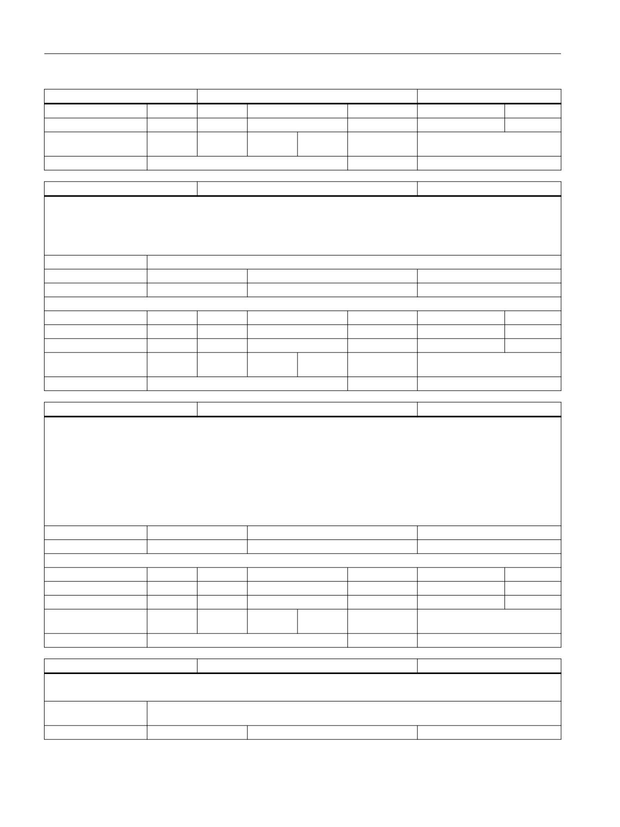
List of system variables
3.2 Channel-specific system variables
$AC_TOFFR
Programmed tool radius offset
DOUBLE
Read:
runin stp
X
7
X
7
-
Write:
-
-
0
-
0
-
Axis entry:
Overlap chan-
channel-specific
nel:
Scan mode:
Not classified
Link:
Not classified
$AC_STOP_COND [10]
Events for the machining stop
INT
Description:
The field variable $AC_STOP_COND[n] determines the events that led to machining stopping in the channel. The events are coded as positive
numerical values in the field elements (see user documentation for meanings). The field element with the field index 0 corresponds to the
highest priority event, higher indexed elements return correspondingly lower priority events. If the nth field element returns the value 0, this
means that there are no further stop events.
Index 1:
Maximum number of simultaneous stop conditions in a channel.
Unit
Init value
Min
Max
-
0
0
2147483647
Read/Write properties:
TP
SA
TP/SA safety
NC-Variable
Safety
OEM-CC
Read:
runin stp
X
7
X
7
X
Write:
-
-
0
-
0
-
Axis entry:
Overlap chan-
channel-specific
nel:
Scan mode:
Not classified
Link:
Not classified
$P_RELFRAME
Active system frame for relative coordinate systems
FRAME
Description:
The variable $P_RELFRAME is used for programming the active system frame for relative coordinate systems.
The system frame is configured in the following machine data:
Bit 11 in $MC_MM_SYSTEM_FRAME_MASK
Bit 11 in $MC_MM_SYSTEM_DATAFRAME_MASK
Bit 11 in $MC_CHSFRAME_RESET_MASK
Bit 11 in $MC_CHSFRAME_RESET_CLEAR_MASK
Bit 11 in $MC_CHSFRAME_POWERON_MASK
Unit
Init value
Min
Max
-
Read/Write properties:
TP
SA
TP/SA safety
NC-Variable
Safety
OEM-CC
Read:
X
-
7
X
7
-
Write:
X
-
7
-
0
-
Axis entry:
GEO
CHAN
MACH
SPIN
Overlap chan-
channel-specific
nel:
Scan mode:
Not classified
Link:
No restrictions
$P_INCOAP_B [n]
Parameters for COA application
BOOL
Description:
Defining and return parameters of the COA application "Cutting generator".
Index 1:
The array size is variable and is defined during power up by the COA application. The system variable $P_IN-
COAP_SIZE[0] can be used to scan the available array size.
Unit
Init value
Min
Max
System variables
188
List Manual, 10/2020, 6FC5397-6AP40-6BA4
List of system variables
3.2 Channel-specific system variables
$P_INCOAP_B [n]
Parameters for COA application
BOOL
-
FALSE
FALSE
TRUE
Read/Write properties:
TP
SA
TP/SA safety
NC-Variable
Safety
OEM-CC
Read:
X
-
7
X
7
-
Write:
X
-
7
X
7
-
Axis entry:
Overlap chan-
channel-specific
nel:
Scan mode:
Not classified
Link:
Not classified
$P_INCOAP_C [n]
Parameters for COA application
CHAR
Description:
Defining and return parameters of the COA application "Cutting generator".
Index 1:
The array size is variable and is defined during power up by the COA application. The system variable $P_IN-
COAP_SIZE[1] can be used to scan the available array size.
Unit
Init value
Min
Max
-
0
0
CHAR_MAX
Read/Write properties:
TP
SA
TP/SA safety
NC-Variable
Safety
OEM-CC
Read:
X
-
7
X
7
-
Write:
X
-
7
X
7
-
Axis entry:
Overlap chan-
channel-specific
nel:
Scan mode:
Not classified
Link:
Not classified
$P_INCOAP_I [n]
Parameters for COA application
INT
Description:
Defining and return parameters of the COA application "Cutting generator".
Index 1:
The array size is variable and is defined during power up by the COA application. The system variable $P_IN-
COAP_SIZE[2] can be used to scan the available array size.
Unit
Init value
Min
Max
-
0
-2147483648
2147483647
Read/Write properties:
TP
SA
TP/SA safety
NC-Variable
Safety
OEM-CC
Read:
X
-
7
X
7
-
Write:
X
-
7
X
7
-
Axis entry:
Overlap chan-
channel-specific
nel:
Scan mode:
Not classified
Link:
Not classified
$P_INCOAP_R [n]
Parameters for COA application
DOUBLE
Description:
Defining and return parameters of the COA application "Cutting generator".
Index 1:
The array size is variable and is defined during power up by the COA application. The system variable $P_IN-
COAP_SIZE[3] can be used to scan the available array size.
Unit
Init value
Min
Max
-
0.0
-1.8E+308
1.8E+308
Read/Write properties:
TP
SA
TP/SA safety
NC-Variable
Safety
OEM-CC
System variables
List Manual, 10/2020, 6FC5397-6AP40-6BA4
189
List of system variables
3.2 Channel-specific system variables
$P_INCOAP_R [n]
Parameters for COA application
DOUBLE
Read:
X
-
7
X
7
-
Write:
X
-
7
X
7
-
Axis entry:
Overlap chan-
channel-specific
nel:
Scan mode:
Not classified
Link:
Not classified
$P_INCOAP_S16 [n]
Parameters for COA application
STRING
Description:
Defining and return parameters of the COA application "Cutting generator".
Index 1:
The array size is variable and is defined during power up by the COA application. The system variable $P_IN-
COAP_SIZE[4] can be used to scan the available array size.
Index 3:
The string must be terminated with \0. The maximum string length is 16 bytes including the terminating null
character.
Unit
Init value
Min
Max
-
""
Read/Write properties:
TP
SA
TP/SA safety
NC-Variable
Safety
OEM-CC
Read:
X
-
7
X
7
-
Write:
X
-
7
X
7
-
Axis entry:
Overlap chan-
channel-specific
nel:
Scan mode:
Not classified
Link:
Not classified
$P_INCOAP_S32 [n]
Parameters for COA application
STRING
Description:
Defining and return parameters of the COA application "Cutting generator".
Index 1:
The array size is variable and is defined during power up by the COA application. The system variable $P_IN-
COAP_SIZE[5] can be used to scan the available array size.
Index 3:
The string must be terminated with \0. The maximum string length is 32 bytes including the terminating null
character.
Unit
Init value
Min
Max
-
""
Read/Write properties:
TP
SA
TP/SA safety
NC-Variable
Safety
OEM-CC
Read:
X
-
7
X
7
-
Write:
X
-
7
X
7
-
Axis entry:
Overlap chan-
channel-specific
nel:
Scan mode:
Not classified
Link:
Not classified
$P_INCOAP_S160 [n]
Parameters for COA application
STRING
Description:
Defining and return parameters of the COA application "Cutting generator".
Index 1:
The array size is variable and is defined during power up by the COA application. The system variable $P_IN-
COAP_SIZE[6] can be used to scan the available array size.
Index 3:
The string must be terminated with \0. The maximum string length is 160 bytes including the terminating null
character.
Unit
Init value
Min
Max
-
""
System variables
190
List Manual, 10/2020, 6FC5397-6AP40-6BA4
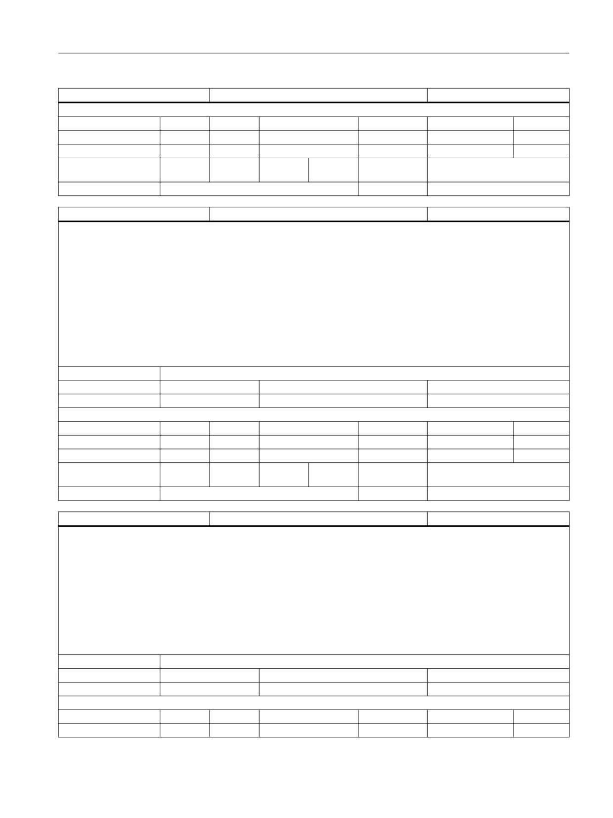
List of system variables
3.2 Channel-specific system variables
$P_INCOAP_S160 [n]
Parameters for COA application
STRING
Read/Write properties:
TP
SA
TP/SA safety
NC-Variable
Safety
OEM-CC
Read:
X
-
7
X
7
-
Write:
X
-
7
X
7
-
Axis entry:
Overlap chan-
channel-specific
nel:
Scan mode:
Not classified
Link:
Not classified
$P_INCOAP_SIZE [n]
Size of parameter fields for COA application
INT
Description:
$P_INCOAP_SIZE[ ] returns the currently available array size of the defining and return parameter $P_INCOAP_<type> of the COA application
"Cutting generator". The array size is variable, and is defined by the COA application during power-up.
The following assignments apply:
$P_INCOAP_SIZE[0] returns the array size of $P_INCOAP_B[ ]
$P_INCOAP_SIZE[1] returns the array size of $P_INCOAP_C[ ]
$P_INCOAP_SIZE[2] returns the array size of $P_INCOAP_I[ ]
$P_INCOAP_SIZE[3] returns the array size of $P_INCOAP_R[ ]
$P_INCOAP_SIZE[4] returns the array size of $P_INCOAP_S16[ ]
$P_INCOAP_SIZE[5] returns the array size of $P_INCOAP_S32[ ]
$P_INCOAP_SIZE[6] returns the array size of $P_INCOAP_S160[ ]
Index 1:
Index: 0 - 6
Unit
Init value
Min
Max
-
0
0
2147483647
Read/Write properties:
TP
SA
TP/SA safety
NC-Variable
Safety
OEM-CC
Read:
X
-
7
X
7
-
Write:
-
-
0
-
0
-
Axis entry:
Overlap chan-
channel-specific
nel:
Scan mode:
Not classified
Link:
Not classified
$AC_SMAXVELO [n]
Maximum possible spindle speed
DOUBLE
Description:
$AC_SMAXVELO[n]
n: Number of the spindle
Maximum possible spindle speed
The variable returns the maximum possible spindle speed for the spindle mode. This is taken from the lowest value of the active speed
limitations, and cannot be exceeded by speed programming or override > 100%.
A speed limitation is displayed by the VDI interface signal DB31..,DBX83.1 'Setpoint speed limited' and by $AC_SPIND_STATE, bit 10 (speed
limitation active).
The cause of the speed limitation can also be determined with the system variable $AC_SMAXVELO_INFO.
In oscillation mode (gear stage change), the variable returns the value for the spindle mode (speed-control mode).
Index 1:
n: Spindle number (0 ... max. spindle number)
Unit
Init value
Min
Max
rpm
0.0
0
1.8E+308
Read/Write properties:
TP
SA
TP/SA safety
NC-Variable
Safety
OEM-CC
Read:
runin stp
X
7
X
7
X
System variables
List Manual, 10/2020, 6FC5397-6AP40-6BA4
191
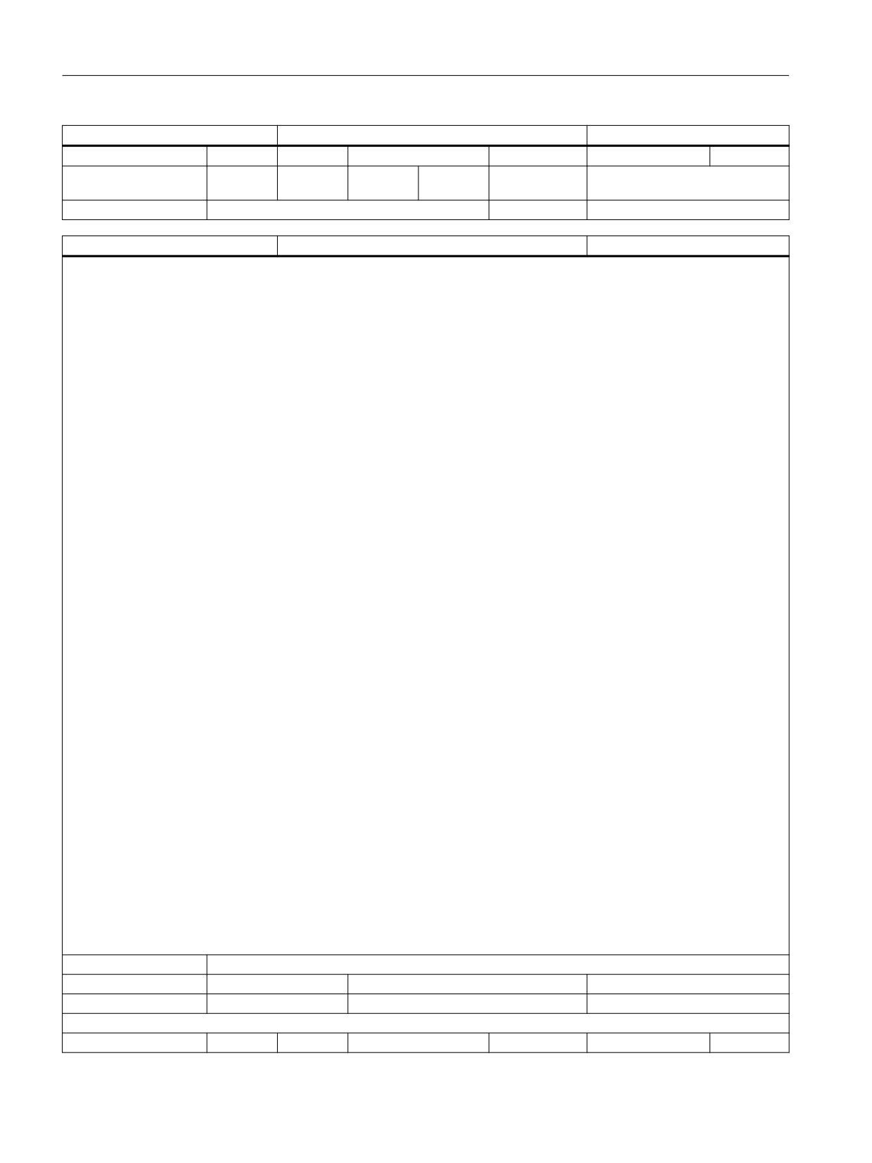
List of system variables
3.2 Channel-specific system variables
$AC_SMAXVELO [n]
Maximum possible spindle speed
DOUBLE
Write:
-
-
0
-
0
-
Axis entry:
Overlap chan-
Cross-channel
nel:
Scan mode:
Not classified
Link:
Not classified
$AC_SMAXVELO_INFO [n]
Identifier for the speed-limiting data
INT
Description:
$AC_SMAXVELO_INFO[n]
n: Number of the spindle
Identifier (info) for the speed limiting data (machine/setting data, etc.).
The system variable is additional information to $AC_SMAXVELO, and returns the
definitive data as an identifier/index. The value read can be used to determine the
speed limiting data from the following table.
0 No limitation (SERUPRO)
1 Maximum speed (chuck speed) of the spindle MD 35100 SPIND_VELO_LIMIT
2 The speed is limited to the maximum speed in the current gear stage MD 35130 GEAR_STEP_MAX_VELO_LIMIT
3 The speed is limited by position control to 90% of the lowest value contained in MD 35100 and MD 35130 (SPCON, SPOS, possibly with
COUPON,..)
4 The speed is limited by position control to MD 35135 GEAR_STEP_PC_MAX_VELO_LIMIT
5 The speed is limited to SD 43220 SPIND_MAX_VELO_G26 (G26 S.. or preset by HMI)
6 The speed is limited to MD 35160 SPIND_EXTERN_VELO_LIMIT because of set VDI interface signal DB31,...DBX3.6
7 The speed is limited to SD 43230 SPIND_MAX_VELO_LIMS with constant cutting speed (G96, G961, G962, G97, LIMS)
8 The speed is limited to safe speed (SS) by Safety Integrated
9 The speed is limited by preparation calculations
10 Limited to the maximum speed of the drive by drive parameter (e.g. SINAMICS p1082, p2000)
11 The speed is limited to MD 36300 ENC_FREQ_LIMIT at functions that require a functioning measuring system, for example, with position
control and G95, G96, G97, G973, G33, G34, G35 for the master spindle. The limitation takes into account the encoder speed, the master
spindle arrangement (direct/indirect), the master spindle limiting frequency and the current parameter set
12 The speed is limited by the axis mode. In the case of a synchronized spindle, axis mode is forced by the leading spindle.
13 The speed of the overlaid motion of the following spindle is limited to the dynamics remaining after the coupling. A larger motion
component of the overlaid motion can be achieved by reducing the leading spindle speed, for example, by programming G26 S, VELOLIM for
the leading spindle or VELOLIMA for the following spindle. The coupling factor has to be taken into account.
14 The speed of the leading spindle is limited by lack of dynamics of the following spindle or a high gear ratio
15 The speed of the master spindle is limited to MD 35550 DRILL_VELO_LIMIT when tapping with G331, G332.
16 The speed is limited by the programming of VELOLIM.
17 The speed is limited by tool parameter $TC_TP_MAX_VELO
18 Not used
19 Not used
20 The speed is limited by the NCU link.
21 The speed is limited by SD43235 SD_SPIND_USER_VELO_LIMIT, speed limited on the user side, e.g. by clamping device, chuck speed
22 The speed is limited by the programming of VELOLIMA
23 The speed is limited by the clamping state of the tool. If there is a Weiss spindle, the clamping state can be read from $VA_MOT_CLAMP-
ING_STATE[axn].
In oscillation mode (gear stage mode), the variable returns the value for spindle mode (speed-control mode)
Index 1:
n: Spindle number (0 ... max. spindle number)
Unit
Init value
Min
Max
-
0
0
17
Read/Write properties:
TP
SA
TP/SA safety
NC-Variable
Safety
OEM-CC
System variables
192
List Manual, 10/2020, 6FC5397-6AP40-6BA4
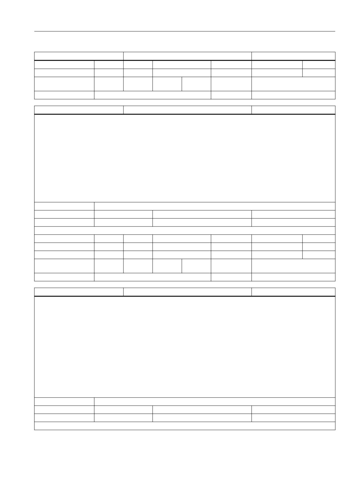
List of system variables
3.2 Channel-specific system variables
$AC_SMAXVELO_INFO [n]
Identifier for the speed-limiting data
INT
Read:
runin stp
X
7
X
7
X
Write:
-
-
0
-
0
-
Axis entry:
Overlap chan-
Cross-channel
nel:
Scan mode:
Not classified
Link:
Not classified
$AC_SMINVELO [n]
Minimum possible spindle speed
DOUBLE
Description:
$AC_SMINVELO[n]
n: Number of the spindle
Minimum possible spindle speed
The variable returns the minimum possible spindle for open-loop speed control mode. This is formed from the highest speed increase, and
cannot be undershot by speed programming or override < 100%
A speed increase is displayed by the VDI interface signal DB31..,DBX83.2 'Setpoint speed increased' and by $AC_SPIND_STATE, bit 11 (setpoint
speed increased).
The cause of the increase in speed (machine or setting data, G code, VDI interface etc.) can also be determined with the system variable
$AC_SMINVELO_INFO.
The increase in speed is effective only if the spindle is in open-loop speed control mode. The system variable always returns the definitive value
for the open-loop speed control mode, even if the spindle is in positioning or axis mode.
Index 1:
n: Spindle number (0 ... max. spindle number)
Unit
Init value
Min
Max
rpm
0.0
0
1.8E+308
Read/Write properties:
TP
SA
TP/SA safety
NC-Variable
Safety
OEM-CC
Read:
runin stp
X
7
X
7
X
Write:
-
-
0
-
0
-
Axis entry:
Overlap chan-
Cross-channel
nel:
Scan mode:
Not classified
Link:
Not classified
$AC_SMINVELO_INFO [n]
Identifier for the speed-raising data
INT
Description:
$AC_SMINVELO_INFO[n]
n: Number of the spindle
Identifier (info) for the speed-increasing data (machine/setting data etc.).
The system variable is additional information to $AC_SMINVELO, and returns the speed-increasing data as an identifier/index for the speed
control mode. The index can be used to determine the speed-increasing data from the following table.
0 Not used
1 Not used
2 Lower speed limit (minimum speed) of the current gear stage MD 35140 GEAR_STEP_MIN_VELO_LIMIT
3 Not used
4 Not used)
5 Lower speed limit (minimum speed) from SD 43210 SPIND_MIN_VELO_G25 (G25 S.. or preset by HMI)
In oscillation mode (gear stage change) and in axis mode, the variable returns values from the spindle mode.
Index 1:
n: Spindle number (0 ... max. spindle number)
Unit
Init value
Min
Max
-
0
0
5
Read/Write properties:
System variables
List Manual, 10/2020, 6FC5397-6AP40-6BA4
193
List of system variables
3.2 Channel-specific system variables
$AC_SMINVELO_INFO [n]
Identifier for the speed-raising data
INT
TP
SA
TP/SA safety
NC-Variable
Safety
OEM-CC
Read:
runin stp
X
7
X
7
X
Write:
-
-
0
-
0
-
Axis entry:
Overlap chan-
Cross-channel
nel:
Scan mode:
Not classified
Link:
Not classified
$AC_SMAXACC [n]
Effective acceleration of the spindle
DOUBLE
Description:
$AC_SMAXACC[n]
n: Number of the spindle
Active acceleration of the spindle.
The variable returns the active acceleration of the spindle for the spindle mode.
$AC_SPIND_STATE, bit 14 (spindle accelerating) is set for the duration of the acceleration to the defined setpoint speed.
$AC_SPIND_STATE, bit 15 (spindle braking) is set for the duration of the braking to the defined setpoint speed.
The data defining the acceleration can be determined with the system variable $AC_SMAXACC_INFO.
In oscillation mode (gear stage change), the variable returns the value for the spindle mode (speed-control mode).
Index 1:
n: Spindle number (0 ... max. spindle number)
Unit
Init value
Min
Max
rps²
0.0
0
1.8E+308
Read/Write properties:
TP
SA
TP/SA safety
NC-Variable
Safety
OEM-CC
Read:
runin stp
X
7
X
7
X
Write:
-
-
0
-
0
-
Axis entry:
Overlap chan-
Cross-channel
nel:
Scan mode:
Not classified
Link:
Not classified
System variables
194
List Manual, 10/2020, 6FC5397-6AP40-6BA4
List of system variables
3.2 Channel-specific system variables
$AC_SMAXACC_INFO [n]
Identifier for the active spindle acceleration data
INT
Description:
$AC_SMAXACC_INFO[n]
n: Number of the spindle
Identifier (info) for the machine data of the currently active spindle acceleration.
The system variable is additional information to $AC_SMAXACC, and returns the definitive data as an identifier/index. The index can be used
to determine the active acceleration data from the following table. The number range is the same as that in the system variable $AC_SMAX-
VELO_INFO:
0 No acceleration limitation (SERUPRO)
1 Not used
2 Acceleration in speed control mode without position control in the current gear stage MD 35200 GEAR_STEP_SPEEDCTRL_ACCEL
3 Not used
4 Acceleration in the current gear stage on account of position control MD 35210 GEAR_STEP_POSCTRL_ACCEL (SPCON, SPOS, possibly with
COUPON,..)
5 Not used
6 Not used
7 Not used
8 Not used
9 Acceleration limited by the preparation calculations
10 Not used
11 Not used
12 Acceleration limited by axis mode. In the case of a synchronized spindle, axis mode is forced by the leading spindle.
13 Acceleration of the overlaid motion of the following spindle is limited to the dynamics remaining after the coupling.
14 Acceleration of the leading spindle is limited by lack of dynamics in the following spindle or a high gear ratio
15 Acceleration of the master spindle MD 35212 GEAR_STEP_POSCTRL_ACCEL2 while tapping with G331, G332 (only with corresponding
configuration of the second data record)
16 Acceleration limited by programming of ACC or ACCFXS (synchronized action)
17 Acceleration limited by tool parameter $TC_TP_MAX_ACCEL
18 Not used
19 MD 32301 MA_JOG_MAX_ACCEL limits the acceleration in JOG mode.
20 Acceleration limited by NCU link.
21 Not used
22 Acceleration limited by programming of ACCLIMA
23 Not used
In oscillation mode (gear stage change), the variable returns the value for spindle mode (speed-control mode).
Index 1:
n: Spindle number (0 ... max. spindle number)
Unit
Init value
Min
Max
-
0
0
17
Read/Write properties:
TP
SA
TP/SA safety
NC-Variable
Safety
OEM-CC
Read:
runin stp
X
7
X
7
X
Write:
-
-
0
-
0
-
Axis entry:
Overlap chan-
Cross-channel
nel:
Scan mode:
Not classified
Link:
Not classified
System variables
List Manual, 10/2020, 6FC5397-6AP40-6BA4
195
List of system variables
3.2 Channel-specific system variables
$AC_SPIND_STATE [n]
Status of the spindle in speed control mode
INT
Description:
$AC_SPIND_STATE[n]
n: Number of the spindle
The variable $AC_SPIND_STATE returns the selected states of the spindle. For positioning and axis mode, the variable $AA_INPOS_STATE[Sn]
can also be read.
Bit 0: "Constant cutting speed active" (VDI interface signal DB31..,DBX84.0)
Bit 1: "GWPS active" (VDI interface signal DB31..,DBX84.1)
Bit 2: "CLGON active" (VDI interface signal DB31..,DBX84.2)
Bit 3: "Tapping without compensating chuck" (VDI interface signal DB31..,DBX84.3)
Bit 4: "Synchronous mode" (following spindle with synchronous spindle coupling) (VDI interface signal DB31..,DBX84.4)
Bit 5: "Positioning mode" (VDI interface signal DB31..,DBX84.5)
Bit 6: "Oscillation mode" (gear stage change) (VDI interface signal DB31..,DBX84.6)
Bit 7: "Open-loop speed control mode" (VDI interface signal DB31..,DBX84.7)
Bit 8: "Spindle programmed" (e.g. M3, M4 S.., FC18, ..) (VDI interface signal DB31..,DBX64.4/5 or 6/7)
Bit 9: "Speed limit exceeded" (VDI interface signal DB31..,DBX83.0)
Bit 10: "Setpoint speed limited" (VDI interface signal DB31..,DBX83.1) active if, as a result of programming or override, the speed would exceed
the maximum possible speed ($AC_SMAXVELO)
Bit 11: "Setpoint speed increased" (VDI interface signal DB31..,DBX83.2) active when, as a result of programming or override, the speed would
fall below the minimum possible speed (system variable $AC_SMINVELO)
Bit 12: "Spindle in setpoint range" (VDI interface signal DB31..,DBX83.5)
Bit 13: "Actual direction of rotation right" (VDI interface signal DB31..,DBX83.7)
Bit 14: "Spindle accelerates" is active as long as the spindle is accelerating to the defined setpoint speed on the setpoint side.
Bit 15: "Spindle brakes" is active as long as the spindle is braking to the defined setpoint speed or to a stop on the setpoint side.
Bit 16: "Spindle stationary" (VDI interface signal DB31..,DBX61.4)
Bit 17: "Tool with dynamic limitation active" (VDI interface signal DB31..,DBX85.0)
Bit 18: Reserved
Bit 19: "Spindle in position" (VDI interface signal DB31..,DBX85.5)
Bit 20: "Position control active" (VDI interface signal DB31..,DBX61.5)
Bit 21: "Referenced/synchronized 1" (VDI interface signal DB31..,DBX60.4)
Bit 22: "Referenced/synchronized 2" (VDI interface signal DB31..,DBX60.5)
Bit 23: The direction of rotation of the spindle is inverted due to the VDI interface signal "Invert M3/M4 " (DB31..,DBX17.6)
Index 1:
n: Spindle number (0 ... max. spindle number)
Unit
Init value
Min
Max
-
0
0
16777215
Read/Write properties:
TP
SA
TP/SA safety
NC-Variable
Safety
OEM-CC
Read:
runin stp
X
7
X
7
X
Write:
-
-
0
-
0
-
Axis entry:
Overlap chan-
Cross-channel
nel:
Scan mode:
Not classified
Link:
Not classified
System variables
196
List Manual, 10/2020, 6FC5397-6AP40-6BA4