SINUMERIK 840D sl. Service - Configuring Commissioning. Manual (2011-2020) - page 92
Switchover from Safety Integrated (system-integrated)
13.2 Comparison of the safety functions
Safety Integrated
Safety Integrated plus
Additional information
Safe Brake Test
SBT
--
--
(SI_BrakeTest [FB11])
Safe Brake Test
SBT
Safe Brake Test
SBT
(SIC/SCC)
(Safe Brake Test)
Safe Cams/cam track
SN
Safe Position
SP
Safe Cams (Page 381)
(Safe position)
Safe Cam
SCA
(Safe Cams)
Internal SOS deselection
--
Internal SOS deselection
--
Dyn. Stop D
--
--
--
--
--
Additional operations for the
--
See also: Instructions for the safe-
safety program of the F-PLC
ty program (Page 58)
See also
Parameterizing EMERGENCY STOP (Page 381)
13.2.2
STOP E
Safety Integrated
Safety Integrated allows STOP E to be initiated with a transition into SBH. To achieve this, the
initiation of ESR must be programmed, taking into account system tags
$AC_ESR_TRIGGER=1 and $VA_STOPSI or $VA_STOPESI. The timer can be
parameterized in p9554 "SI Motion transition time from STOP E to SBH" (drive monitoring
channel) and in the MD36954 $MA_SAFE_STOP_SWITCH_TIME_E (NC monitoring channel).
The initiation of STOP E - as a result of a fault - can be realized using PLC-SPL-CDC, FSEND-
FRECV communication or F-I/O fault (Page 390). The acknowledgment or the deselection can
be realized, either using a NC RESET or e.g. in the PLC program using SGE "Deselect ext.
STOP E" in "<axis DB>.DBX32.5".
Safety Integrated plus
Safety Integrated plus only supports STOP E as parameterizable fault response of safety
functions SLS and SLP. All safety functions can be parameterized in dedicated SINUMERIK
Operate screen forms. In the screen forms you can also set the fault response and the delay
time.
Safety Integrated plus
Commissioning Manual, 12/2019, 6FC5397-1FP40-6BA3
379
Switchover from Safety Integrated (system-integrated)
13.2 Comparison of the safety functions
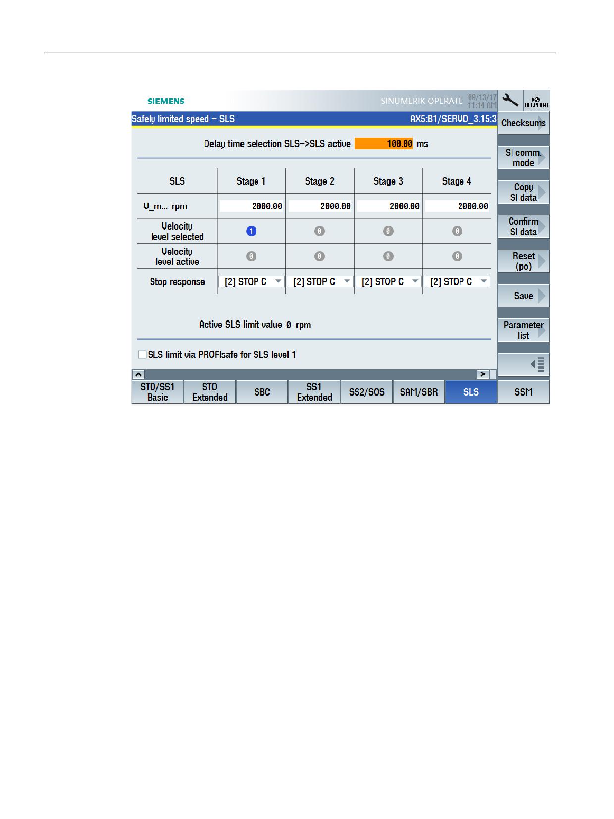
Figure 13-1
Selecting STOP E as stop response for SLS
SLS is acknowledged or deselected with STOP E in the safety program of the F-PLC by
resetting the corresponding bits in the drive addresses (via PROFIsafe telegram) - and
additional safety-relevant acknowledgment (PROFIsafe IEACK) along with a PROFIdrive reset.
See also: Acknowledgment (Page 327), Deselecting safety functions integrated in the drive
(Page 233).
For Safety Integrated plus, system tags $VA_STOPSI and $VA_STOPESI are also supplied.
13.2.3
SG override
Safety Integrated
Safety Integrated allows up to 4 safety-relevant velocity values to be used. Safety-relevant
velocities SG2 and SG4 can also be assigned 16 different percentage values, so that 34
different velocity values are available for each axis.
Safety Integrated plus
4 safety-relevant velocity values are also available for Safety Integrated plus. You can set these
4 values in the function-specific SINUMERIK Operate screen form.
In addition, the 1st safety-relevant velocity level can be assigned percentage values between
0 and 100% - to achieve a high level of granularity. To do this, in the associated screen form,
activate option "SLS limit via PROFIsafe for SLS level 1" - and in the safety program, access
the corresponding bit using the PROFIsafe telegram.
Safety Integrated plus
380
Commissioning Manual, 12/2019, 6FC5397-1FP40-6BA3
Switchover from Safety Integrated (system-integrated)
13.2 Comparison of the safety functions
This means that theoretically more than a 32,000 values can be defined.
13.2.4
Safe Cams
Safety Integrated
With Safety Integrated, depending on the particular application, you use the "Safe Software
Cams" or "Safe Cam Track" safety function.
● With "Safe software cams", up to 4 cam pairs are available for each axis. Here, the
precondition is that the axes involved are safely referenced.
● Alternatively, the "Safe Cam Track" function can be used, which can be used to evaluate a
total of 30 cams. Here, up to 4 cam tracks - with a maximum of 15 cams per cam track - are
available.
In both cases, you must configure the cams using the appropriate machine data or drive
parameters. SGA with information about the cams can be evaluated using Safe Programmable
Logic (SPL).
Safety Integrated plus
Safety Integrated plus allows safety-relevant cams to be implemented using two different
safety functions:
● Safety function SCA (Safe Cam) allows up to 30 safety-relevant cams per axis to be directly
configured in a function-specific SINUMERIK Operate screen form. To use this safety
function, you require process data S_ZSW_CAM1, which is only available in SIEMENS
telegram 903.
● SP (Safe Position) allows safety-relevant position values to be transferred (process data
S_XIST32) in SIEMENS telegram 902. The safety-relevant position values can be
evaluated in the F-PLC safety program to implement safety-relevant cams.
13.2.5
Parameterizing EMERGENCY STOP
For EMERGENCY STOP shutdowns, for Safety Integrated, the PLC basic program block
"SI_relay [FB10]" was used in conjunction with the corresponding NC SPL syntax for SI relay.
For example, when actuating an EMERGENCY STOP pushbutton, a STOP C or STOP D can
be initiated with delayed STOP A. The same EMERGENCY STOP shutdown operations can
also be implemented when using Safety Integrated plus:
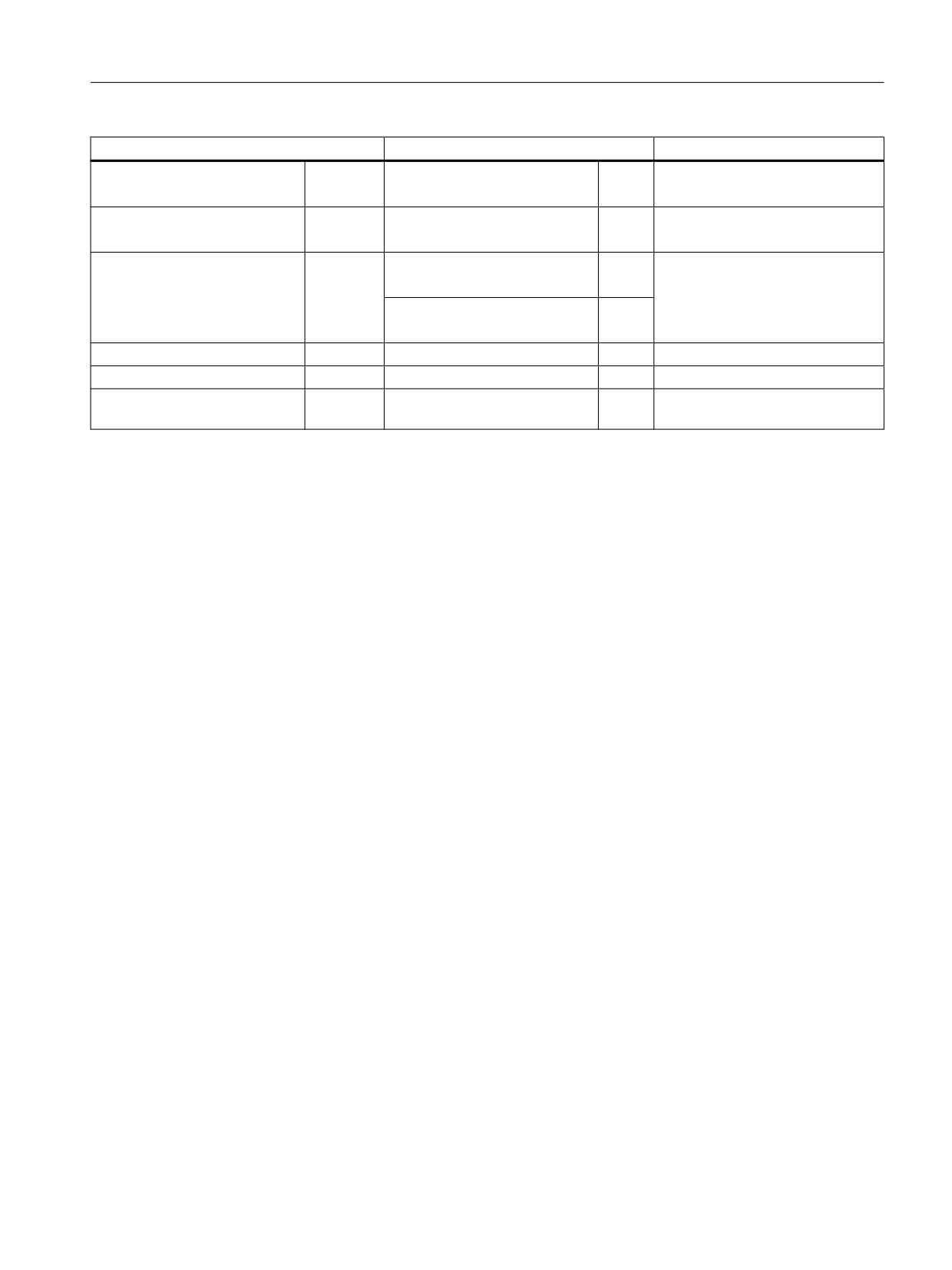
Table 13-2
Examples of EMERGENCY STOP shutdown operations in Safety Integrated and Safety
Integrated plus that can be parameterized
Safety Integrated
Safety Integrated plus
Ext. Stop C → Δt → STOP A
SS1
Ext. Stop D → Δt → STOP A
SS2e → Δt → STO
Safety Integrated plus
Commissioning Manual, 12/2019, 6FC5397-1FP40-6BA3
381
Switchover from Safety Integrated (system-integrated)
13.2 Comparison of the safety functions
Further, for Safety Integrated, external I/O devices can be shut down in a safety-relevant way
using an SI-relay.
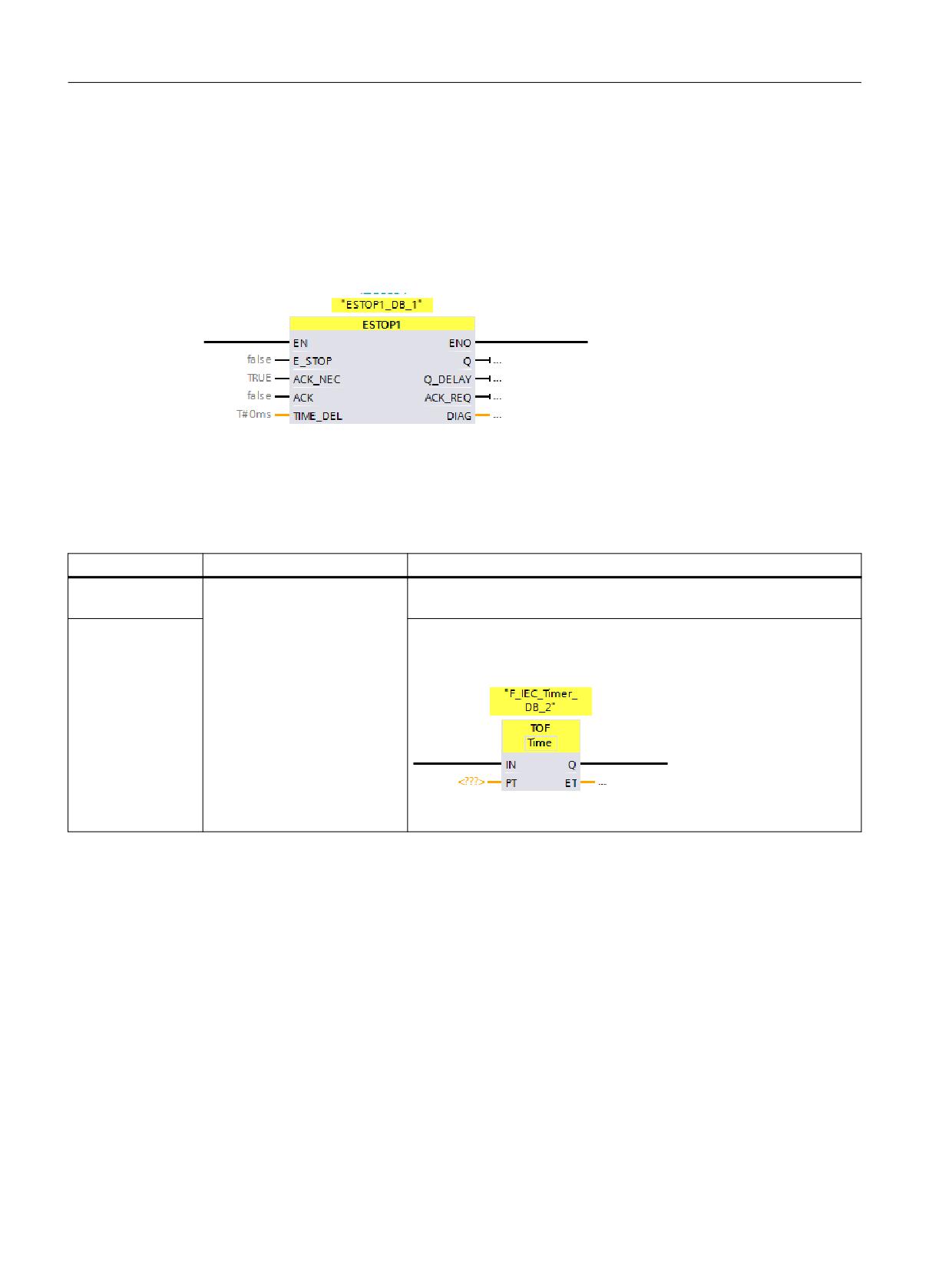
Instead of this function, for Safety Integrated Plus, the certified ESTOP1 operation is available.
Instruction ESTOP1 can be used to control the required stopping requirements in SINAMICS
Safety Integrated as well as the F-I/O.
The following differences exist when parameterizing the switch-off delay time of the
EMERGENCY STOP signal:
Table 13-3
Parameterizing the delay time of the EMERGENCY STOP signal
Delay time
Safety Integrated
Safety Integrated plus
Drive components
The safety relay block has 3
Parameterize the switch-off delay time directly in the SINUMERIK Op-
timers for different delay times.
erate screen form for the corresponding safety function.
F-I/O
You can specify 1 time in parameter Q_DELAY of the ESTOP1 oper-
ation. You can use the TOF operation for each additional delay time
that is required.
Safety Integrated plus
382
Commissioning Manual, 12/2019, 6FC5397-1FP40-6BA3

Switchover from Safety Integrated (system-integrated)
13.3 Additional differences when commissioning
13.3
Additional differences when commissioning
13.3.1
Overview
Several commissioning steps and functions of Safety Integrated plus and the corresponding
functions of Safety Integrated are compared in the following.
Commissioning step
Safety Integrated (SPL)
Safety Integrated plus (F-PLC)
Maximum number of axes that are
31 axes per NCU, of which, a maxi-
31 axes per NCU, of which, a maximum of 4
supported
mum of 6 can be connected to one
can be connected to one DRIVE CLiQ line.
DRIVE CLiQ line.
See also: AUTOHOTSPOT
Commissioning the F-I/O
Configuring in STEP 7 and parame-
Configuring and parameterizing the F-I/O in
terizing - partially redundantly - in
STEP 7 (TIA Portal).
STEP 7 and in SINUMERIK Oper-
See: Commissioning the F-I/O (Page 384)
ate using machine data.
Commissioning the safety functions
Commissioning in SINUMERIK Op-
SI drives and drive-integrated safety functions
erate using machine data that can
are commissioned using function-specific
be filtered and in some instances
screen forms in SINUMERIK Operate
using function-specific screen
See: Parameterizing the safety functions
forms.
(Page 387)
Programming the safety logic
Redundant programming as NC-
The complete safety program is programmed
SPL program (SAFE.SPF) and
in the TIA Portal using the operating concepts
PLC-SPL program.
known from standard PLC user programs. LAD
and FBD programming languages are used
with a scope of operations adapted to F-blocks.
F-I/O are accessed using system
F-I/O and drive telegrams are accessed via the
tags or data block "SPL [DB18]";
process image in the safety program and PLC
safety functions of the drives are ac-
user program. Some system tags are also
cessed (axis-specific SGE/SGA)
used.
via system tags or axis-DBs
See: Accessing status/control information
(Page 392)
Accessing status/control signals
Access is mainly realized via axis/
Access to process data of the telegrams, the
channel DB, SPL [DB18] and NC/
process image and F-I/O DB.
system tags.
See: Accessing status/control information
(Page 392)
Fault response to F-I/O faults
A fault message is displayed fol-
A fault message is displayed, the stop re-
lowed by a stop response for all ax-
sponse has to be configured depending on the
es
specific situation.
Configuring a fault response to com-
Passivation, provision of substitute
Passivation of the F-I/O or drive components
munication faults/errors
values for FSEND/FRECV, system-
involved, provision of substitute values
related STOP D/E response can be
(FSEND/FRECV), additional response can be
parameterized, additional response
configured.
can be configured.
See: Fault response and acknowledgment for
F-I/O faults (Page 390)
Safety Integrated plus
Commissioning Manual, 12/2019, 6FC5397-1FP40-6BA3
383
Switchover from Safety Integrated (system-integrated)
13.3 Additional differences when commissioning
Commissioning step
Safety Integrated (SPL)
Safety Integrated plus (F-PLC)
Acknowledging after a communica-
User acknowledgment using inter-
User acknowledgment by configuring an ac-
tion faults/errors
face signal DB18.FRDP_ACK_REI
knowledgment button with assignment to the
- and via a channel_1 reset.
corresponding F-I/O DB tag ("ACK_GL" or
"ACK_GLOB") and channel_1 reset (PROFI-
drive reset).
See: Fault response and acknowledgment for
F-I/O faults (Page 390)
See also: Implementing user acknowledgment
for global reintegration (Page 228).
Evaluating alarms using the NC
The NC checks safety alarms, and if
As Safety Integrated plus uses the safety func-
necessary suppresses an alarm, pri-
tions integrated in the drive, the NC does not
oritizes an alarm - or checks alarm
suppress alarms, prioritize alarms or check
numbers.
alarm numbers of safety messages of the drive.
See also: General information
about displaying and evaluating di-
agnostic information (Page 313)
13.3.2
Commissioning the F-I/O
Safety Integrated
Initially, you configure and parameterize the F-I/O in STEP 7. You then load the configuration
to the NCU, and also enter some settings in the machine data:
● F-source addresses (PROFIsafe addresses of the F-master)
● F-destination addresses (PROFIsafe addresses of the F-DI-/F-DO modules)
● Allocate symbolic names for F-modules (optional)
● Distribution of the computational load on the NC side
● Select F-user data signals to be transferred in the SPL (F-user data filter)
● Assign F-user data signals to be transferred to the SPL-SGE/SGA
Safety Integrated plus
You configure and parameterize the F-I/O completely in STEP 7 (TIA Portal).
Safety Integrated plus
384
Commissioning Manual, 12/2019, 6FC5397-1FP40-6BA3
Switchover from Safety Integrated (system-integrated)
13.3 Additional differences when commissioning
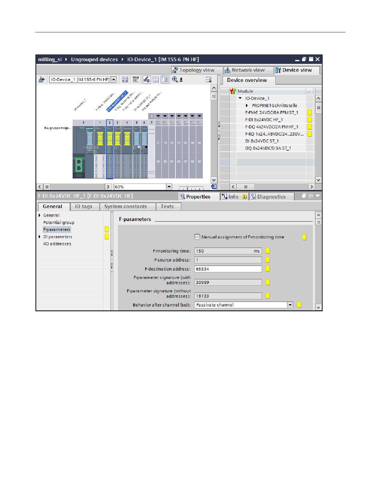
Figure 13-2
F-parameters of an F-DI
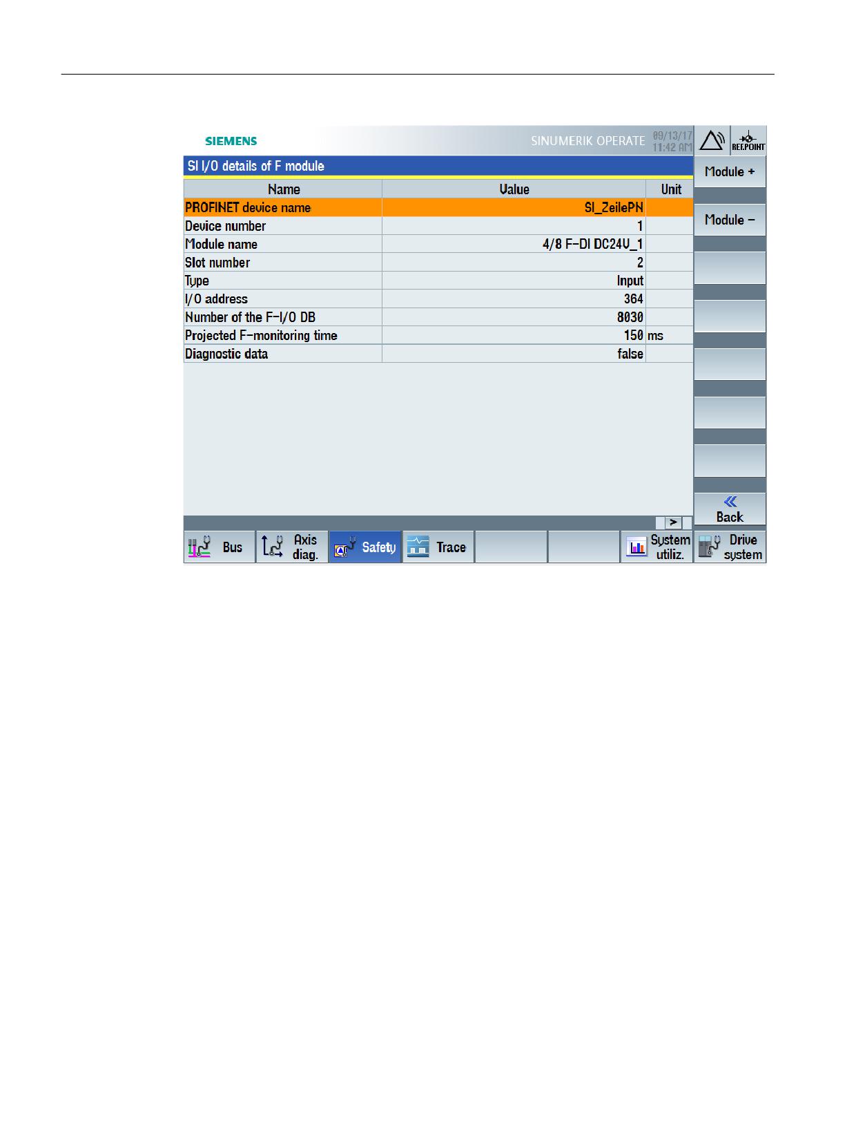
After you have loaded the configuration to the NCU, the F-I/O parameterization is automatically
accepted, and you can, for example, display detailed and diagnostic information relating to the
F-I/O directly in SINUMERIK Operate.
Safety Integrated plus
Commissioning Manual, 12/2019, 6FC5397-1FP40-6BA3
385
Switchover from Safety Integrated (system-integrated)
13.3 Additional differences when commissioning
Figure 13-3
Parameterization of an F-module taken from the TIA Portal configuration
Safety Integrated plus
386
Commissioning Manual, 12/2019, 6FC5397-1FP40-6BA3
Switchover from Safety Integrated (system-integrated)
13.3 Additional differences when commissioning
13.3.3
Parameterizing the safety functions
Safety Integrated
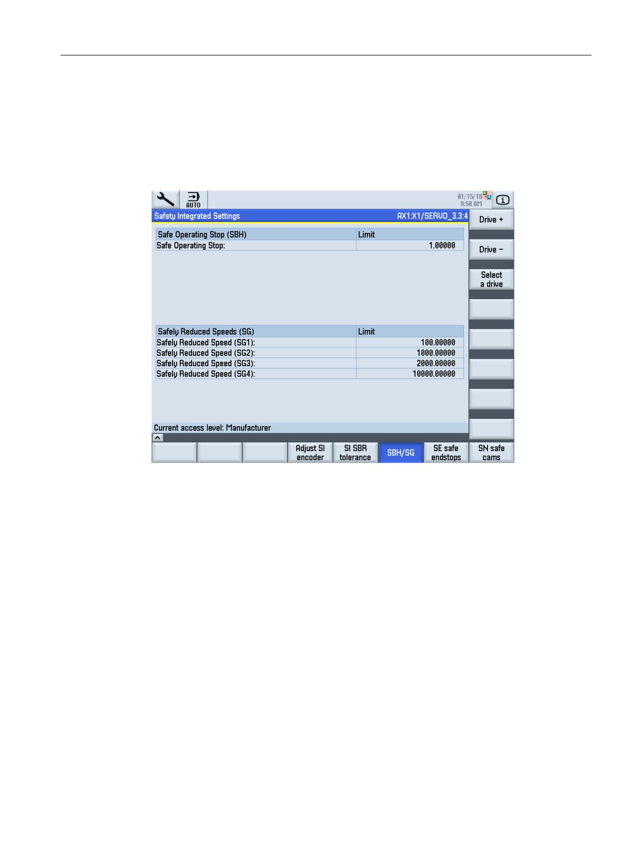
SINUMERIK Operate has function-specific (generally tabular) screen forms to enter some
general safety-relevant settings - as well as for the safety functions SBR, SBH/SG, SBC, safety-
relevant end positions and safety-relevant cams.
Figure 13-4
Parameterizing a safety function (SBH/SG)
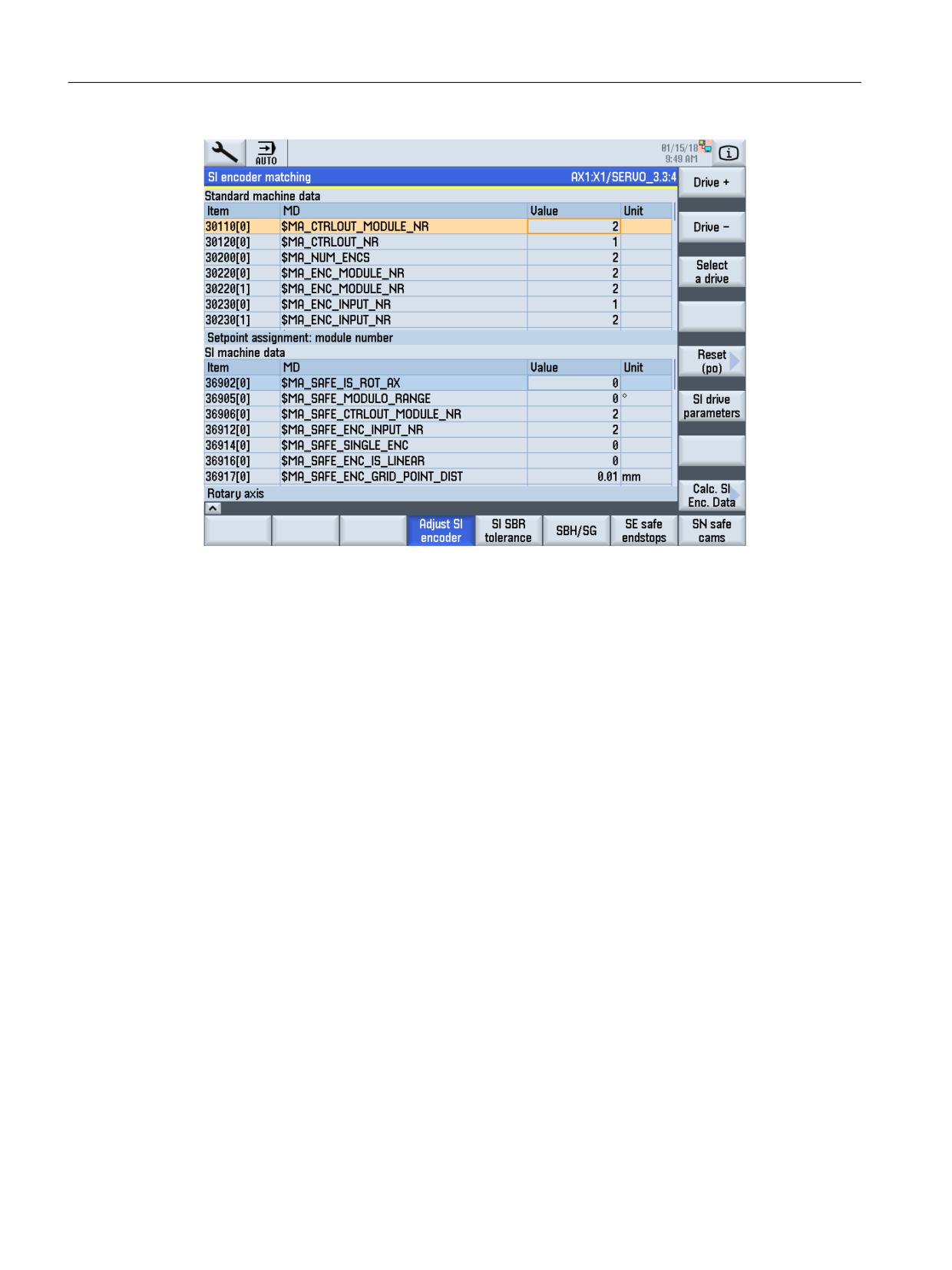
Additional settings and safety functions should be configured in SINUMERIK Operate using
machine data and drive parameters that can be filtered.
Safety Integrated plus
Commissioning Manual, 12/2019, 6FC5397-1FP40-6BA3
387
Switchover from Safety Integrated (system-integrated)
13.3 Additional differences when commissioning
Figure 13-5
Parameterizing using machine data (SI encoder adaptation)
Safety Integrated plus
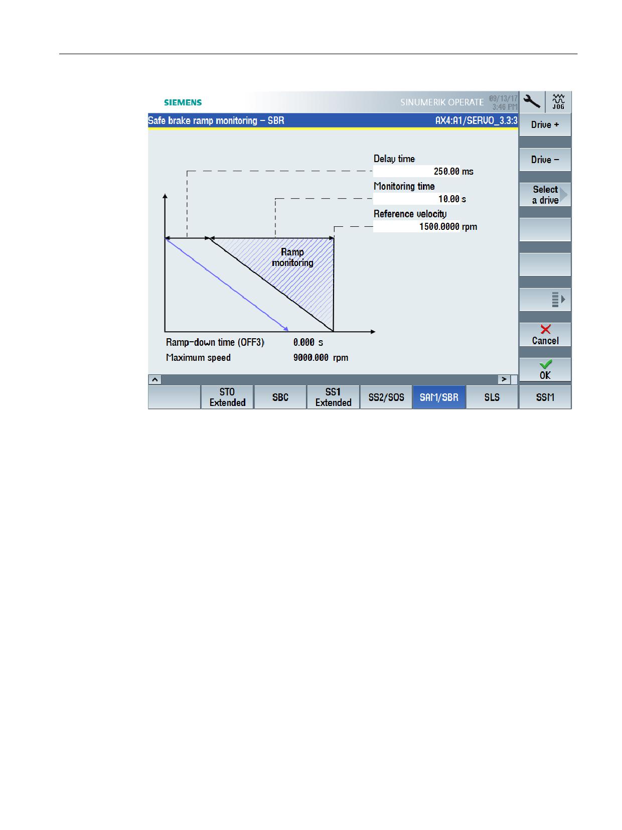
All of the drive-integrated safety functions as well as higher-level or general settings can be
configured using function-specific graphic SINUMERIK Operate screen forms.
Safety Integrated plus
388
Commissioning Manual, 12/2019, 6FC5397-1FP40-6BA3
Switchover from Safety Integrated (system-integrated)
13.3 Additional differences when commissioning
Figure 13-6
Parameterizing a safety function (SBR)
The "Recommended values" softkey is available as supplementary function; this allows
recommended values to be automatically calculated and entered. The basis for the calculated
recommended values is the corresponding equations to be taken into account for manual
parameterization.
Alternatively, all safety-relevant settings can be made in tabular expert lists ("Parameter list"
softkey), in which all parameters are listed which involve the corresponding safety function
Safety Integrated plus
Commissioning Manual, 12/2019, 6FC5397-1FP40-6BA3
389
Switchover from Safety Integrated (system-integrated)
13.3 Additional differences when commissioning
13.3.4
Fault response and acknowledgment for F-I/O faults
Safety Integrated
In the context of Safety Integrated, F-I/O faults are identified by evaluating the PROFIsafe
status of F-I/O devices. A system response is initiated if such a fault occurs:
Error detected by
System response
Drive/NC-CDC
STOP F
SPL-CDC
STOP D/E
(Redundant configuration of the stop response to be initiated in the machine
data and in data block SPL [DB18].)
Communication CDC
The SGE/SGA involved are brought into a failsafe state (substitute values
are provided). Substitute values can be specified.
Additional system-specific responses can be configured by reading out
DB18.DBX119.5.
Generally, the system response can involve passivation of all of the F-I/O modules - or only
those of the channel involved. The cause of the fault must be removed and acknowledged in
order to remove the fault and to reset the system response.
Safety Integrated plus
Safety Integrated plus responds to F-I/O faults by providing substitute values, i.e. passivation is
realized.
Safety Integrated plus
390
Commissioning Manual, 12/2019, 6FC5397-1FP40-6BA3
Switchover from Safety Integrated (system-integrated)
13.3 Additional differences when commissioning
The following options exist to adapt and supplement the response:
● Passivate all of the F-I/O modules - or only those of the channel involved.
● Reintegration (depassivation) of the F-I/O automatically, depending on the configuration,
with a user acknowledgment.
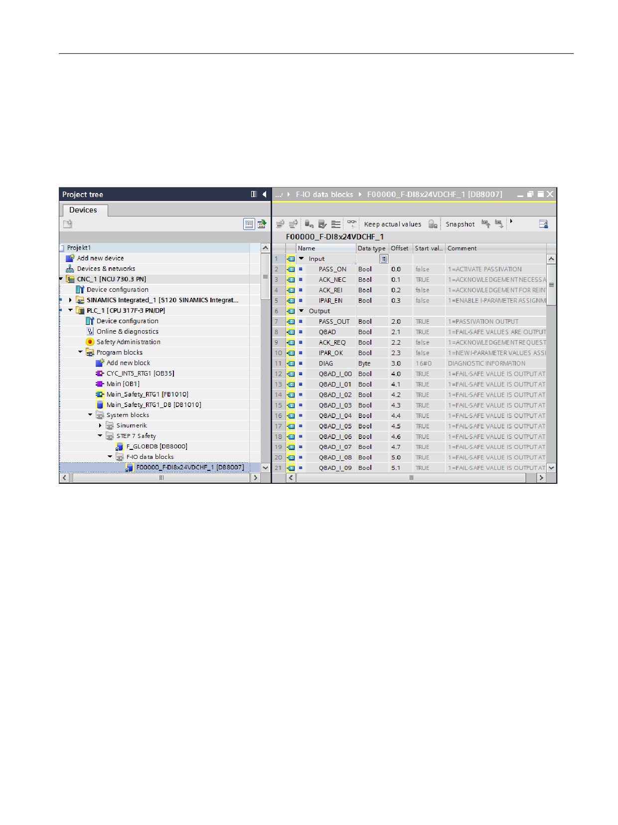
● In addition, each F-I/O has its own F-I/O DB. This means that you can access status
information and program user-specific system responses.
Figure 13-7
Example of an F-I/O DB
Additional information
● Implementing user acknowledgment for global reintegration (Page 228)
● System alarms and diagnostic screens for F-PLC and F-I/O. (Page 298)
Safety Integrated plus
Commissioning Manual, 12/2019, 6FC5397-1FP40-6BA3
391
Switchover from Safety Integrated (system-integrated)
13.3 Additional differences when commissioning
13.3.5
Accessing status/control information
As the safety functions of the two safety operating modes are implemented using different
subcomponents, there are some fundamental differences regarding the control options:
Access from → to
Safety Integrated
Safety Integrated plus
PLC program → F-I/O
SPL [DB18]
Process image
PLC program → drive
PLC program → safety function
Axis-specific signals for the sys-
Process data in telegrams (PRO-
tem-integrated safety functions
FIsafe, SIC/SCC)
PLC program → safety-relevant
in <axis DB>.DB22 … <axis
setting
DB>.DB125.
Axis-specific signals for drive-integrated safety functions in <axis
DB>.DB140 … <axis DB>.DB187 (mapped from SIC).
Control via terminals for drive-integrated safety functions (Basic
Functions)
∼ 20 NC variables
5 NC variables (mapped from
SIC)
NC part program → safety func-
∼ 50 system variables
2 system variables (mapped
tion
from SIC)
NC part program → safety-rele-
vant setting
Safety Integrated
For Safety Integrated, the basic PLC program automatically connects the I/O (F-user data) of
an F-module to the SPL interface in data block SPL [DB18]. It is not possible to connect them
in a PLC user program.
The safety functions are accessed on an axis-for-axis basis.
Safety Integrated plus
For Safety Integrated plus, F-I/O and safety-relevant drive telegrams are accessed via the
process image, as is the case for the standard I/O. The PLC user program can access this
status/control information, therefore allowing functional expansions to be made.
Safety functions are accessed on an axis-for-axis basis.
Safety Integrated plus
392
Commissioning Manual, 12/2019, 6FC5397-1FP40-6BA3
Switchover from Safety Integrated (system-integrated)
13.4 Procedure when switching over between systems
13.4
Procedure when switching over between systems
It is not possible to automatically migrate the safety functions from Safety Integrated to Safety
Integrated plus.
● The safety-relevant program code used in the two safety modes differs significantly. This
relates to the programming language and operations - as well as the positions and/or blocks
from where the safety program can be called.
● Instead of the safety functions of Safety Integrated integrated in the system, for Safety
Integrated plus, the drive-based safety functions of SINAMICS Safety Integrated are used;
although they are functionally comparable, they use different parameters and values
however.
However, the existing risk analysis and the safety concept can be used to create a new safety
program on this basis - and to configure the drive-integrated safety functions.
Fundamental approach when switching over
The procedure can be roughly split-up into the following steps:
1. Migrating a STEP 7 V5.x project to the TIA Portal
Safety Integrated plus is supported from SINUMERIK STEP 7 toolbox V14 (TIA Portal).
Information about migrating the standard components of a STEP 7 5.x project into the
TIA Portal is provided in the TIA Portal online help, search terms "Migrating SINUMERIK
PLC projects" and "Migrating PLC project".
2. Deleting components of the Safety Integrated (SPL) program from the TIA Portal project:
- Remove the access operations to SPL function blocks or functions - and to SPL data
blocks signals from your PLC user program.
(you can use the following commands to find these locations: "Cross-references" in the
shortcut menu of an SPL block, "Browse project" in the shortcut menu of the program
block folder)
- Delete the Safety Integrated (SPL) blocks used in the project:
SI_relay [FB10]
SI_BrakeTest [FB11]
SPL [DB18]
Additional blocks (e.g. test stop blocks "SI Pulse Teststop SL [FC264]", "SI External Stop
SL [FC265]")
3. Adapting the configuration (Page 214)
4. Setting the safety program (Page 223)
5. Commissioning safety functions integrated in the drive
- Comparison of the functions (Page 378)
- Configuring NC and drive-specific safety settings (Page 239)
- Safety functions integrated in the drive (Page 79)
Safety Integrated plus
Commissioning Manual, 12/2019, 6FC5397-1FP40-6BA3
393
Preface
Fundamental safety
1
instructions
2
Introduction
SINUMERIK
3
List of system variables
SINUMERIK 840D sl
System variables
A
Appendix A
List Manual
Valid for:
Control
SINUMERIK 840D sl / 840DE sl
Software
CNC software, Version 4.94
10/2020
6FC5397-6AP40-6BA4
Table of contents
Preface
3
1
Fundamental safety instructions
7
1.1
General safety instructions
7
1.2
Warranty and liability for application examples
7
1.3
Security information
7
2
Introduction
9
2.1
Elements of a system variables table
9
2.2
Structure of a system variables table
10
2.3
Channel-specific and NC-global arithmetic parameters (R / RG)
11
2.4
Supplementary conditions
12
3
List of system variables
13
3.1
Channel-specific synchronized action variables
13
3.2
Channel-specific system variables
14
3.3
Frames
272
3.4
Channel-specific protection zones
278
3.5
Tool holder data
284
3.6
Tool parameters
306
3.7
OEM user cutting edge data
320
3.8
Tool management monitoring data
390
3.9
OEM user monitoring data
394
3.10
Tool-related data
419
3.11
Tool-related grinding data
448
3.12
Magazine location data
452
3.13
OEM user magazine location data
456
3.14
Tool management magazine description data
483
3.15
OEM user tool management magazine description data
487
3.16
Magazine module parameters
511
3.17
Adapter data
513
3.18
Multitool data
517
3.19
Measurement system compensation values
573
3.20
Interpolatory compensation
575
System variables
List Manual, 10/2020, 6FC5397-6AP40-6BA4
5
Table of contents
3.21
NC-specific protection zones
579
3.22
Cycles parameterization
585
3.23
System data
617
3.24
Axial system variables
659
3.25
Safety Integrated
787
3.26
User-specific system variables
806
3.27
Kinematic chain
826
3.28
Orientation transformation
829
3.29
Protection area elements
847
3.30
Coordinate system-specific working area limitation
856
3.31
Tool data ISO dialect milling
858
3.32
Tool data ISO dialect turning
859
A
Appendix A
863
A.1
List of abbreviations
863
A.2
Documentation overview SINUMERIK 840D sl
869
Index
871
System variables
6
List Manual, 10/2020, 6FC5397-6AP40-6BA4
Fundamental safety instructions
1
1.1
General safety instructions
WARNING
Danger to life if the safety instructions and residual risks are not observed
If the safety instructions and residual risks in the associated hardware documentation are not
observed, accidents involving severe injuries or death can occur.
• Observe the safety instructions given in the hardware documentation.
• Consider the residual risks for the risk evaluation.
WARNING
Malfunctions of the machine as a result of incorrect or changed parameter settings
As a result of incorrect or changed parameterization, machines can malfunction, which in turn
can lead to injuries or death.
• Protect the parameterization against unauthorized access.
• Handle possible malfunctions by taking suitable measures, e.g. emergency stop or
emergency off.
1.2
Warranty and liability for application examples
Application examples are not binding and do not claim to be complete regarding configuration,
equipment or any eventuality which may arise. Application examples do not represent specific
customer solutions, but are only intended to provide support for typical tasks.
As the user you yourself are responsible for ensuring that the products described are operated
correctly. Application examples do not relieve you of your responsibility for safe handling when
using, installing, operating and maintaining the equipment.
1.3
Security information
Siemens provides products and solutions with industrial security functions that support the
secure operation of plants, systems, machines and networks.
In order to protect plants, systems, machines and networks against cyber threats, it is necessary
to implement - and continuously maintain - a holistic, state-of-the-art industrial security
concept. Siemens’ products and solutions constitute one element of such a concept.
Customers are responsible for preventing unauthorized access to their plants, systems,
machines and networks. Such systems, machines and components should only be connected to
System variables
List Manual, 10/2020, 6FC5397-6AP40-6BA4
7
Fundamental safety instructions
1.3 Security information
an enterprise network or the internet if and to the extent such a connection is necessary and only
when appropriate security measures (e.g. firewalls and/or network segmentation) are in place.
For additional information on industrial security measures that may be implemented, please
visit
Siemens’ products and solutions undergo continuous development to make them more secure.
Siemens strongly recommends that product updates are applied as soon as they are available
and that the latest product versions are used. Use of product versions that are no longer
supported, and failure to apply the latest updates may increase customer’s exposure to cyber
threats.
To stay informed about product updates, subscribe to the Siemens Industrial Security RSS Feed
under
services/cert.html#Subscriptions).
Further information is provided on the Internet:
Industrial Security Configuration Manual (https://support.industry.siemens.com/cs/ww/en/
view/108862708)
WARNING
Unsafe operating states resulting from software manipulation
Software manipulations, e.g. viruses, Trojans, or worms, can cause unsafe operating states in
your system that may lead to death, serious injury, and property damage.
• Keep the software up to date.
• Incorporate the automation and drive components into a holistic, state-of-the-art industrial
security concept for the installation or machine.
• Make sure that you include all installed products into the holistic industrial security concept.
• Protect files stored on exchangeable storage media from malicious software by with suitable
protection measures, e.g. virus scanners.
• On completion of commissioning, check all security-related settings.
System variables
8
List Manual, 10/2020, 6FC5397-6AP40-6BA4
Introduction
2
2.1
Elements of a system variables table
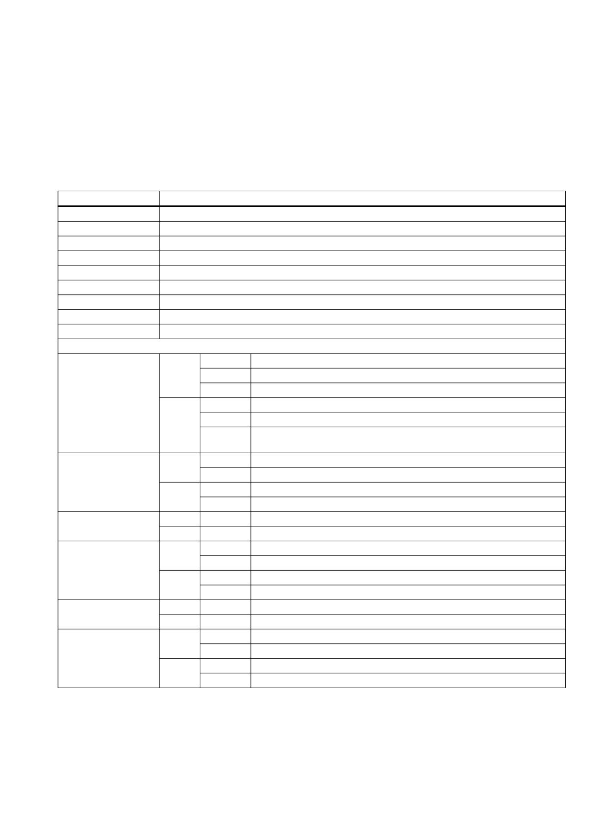
Field name
Meaning
Identifier
Name of system variables, optional with up to three indexes in square brackets
Brief description
Brief description of the system variables in a single block
Data type
Data type of the system variables, e.g. BOOL, BYTE, CHAR, INT, REAL, AXIS, FRAME, STRING
Description
Detailed description of the system variables.
Index 1 - Index n
Description and value range for index 1 ...n (optional)
Unit
Unit of the system variables, e.g. mm, s, degrees, m/s, m/s2, m/s3
Default value
Default value of the system variables
Minimum value
Minimum value of the system variables
Maximum value
Maximum value of the system variables
Properties of reading / writing the system variables
PP (part program)
Read
-
Reading in part program is not possible
X
Reading in part program is possible, no preprocessing stop occurs
VL_Stop
Reading in part program is possible, a preprocessing stop occurs
Write
X
Writing in part program is possible, no preprocessing stop occurs
VL_Stop
Writing in part program is possible, a preprocessing stop occurs
HL_Sync
Writing in part program is possible; it is performed synchronously with the
main run
SA (synchronized ac-
Read
-
Reading in a synchronized action is not possible
tion)
X
Reading in a synchronized action is possible
Write
-
Writing in a synchronized action is not possible
X
Writing in a synchronized action is possible
PP / SA access level
Read
0 - 7
Protection level for reading in part programs or synchronized actions
Write
0 - 7
Protection level for writing in part programs or synchronized actions
NC variable
Read
-
Reading via an NC variable or OPI is not possible
X
Reading via an NC variable or OPI is possible
Write
-
Reading via an NC variable or OPI is not possible
X
Writing via an NC variable or OPI is possible
Access level
Read
0 - 7
Protection level for reading via an NC variable or OPI
Write
0 - 7
Protection level for writing via an NC variable or OPI
OEM-CC
Read
-
Reading in a compile cycle or CC-binding is not possible
X
Reading in a compile cycle or CC-binding is not possible
Write
-
Writing in a compile cycle or CC-binding is not possible
X
Writing in a compile cycle or CC-binding is possible
System variables
List Manual, 10/2020, 6FC5397-6AP40-6BA4
9
Introduction
2.2 Structure of a system variables table
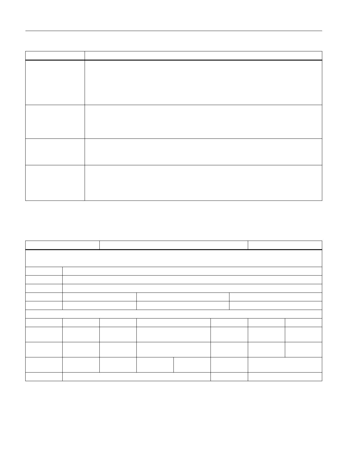
Field name
Meaning
Axis identifier
Permitted name of axis-specific indexes:
• GEO Geometry axis names
• CHAN: Channel axis names
• MACH: Machine axis name
• SPIN: Spindle name
Value determination
Properties relating to value determination:
• Channel-specific: value of the variables in the active channel
• Cross-channel: value of the axis-specific variables in the channel in which the axis is currently
active
Block search
Properties of the block search:
• Not classified
• program-sensitive
Link
Properties of the NCU link:
• No restrictions
• Not classified
• Lead-link axis
2.2
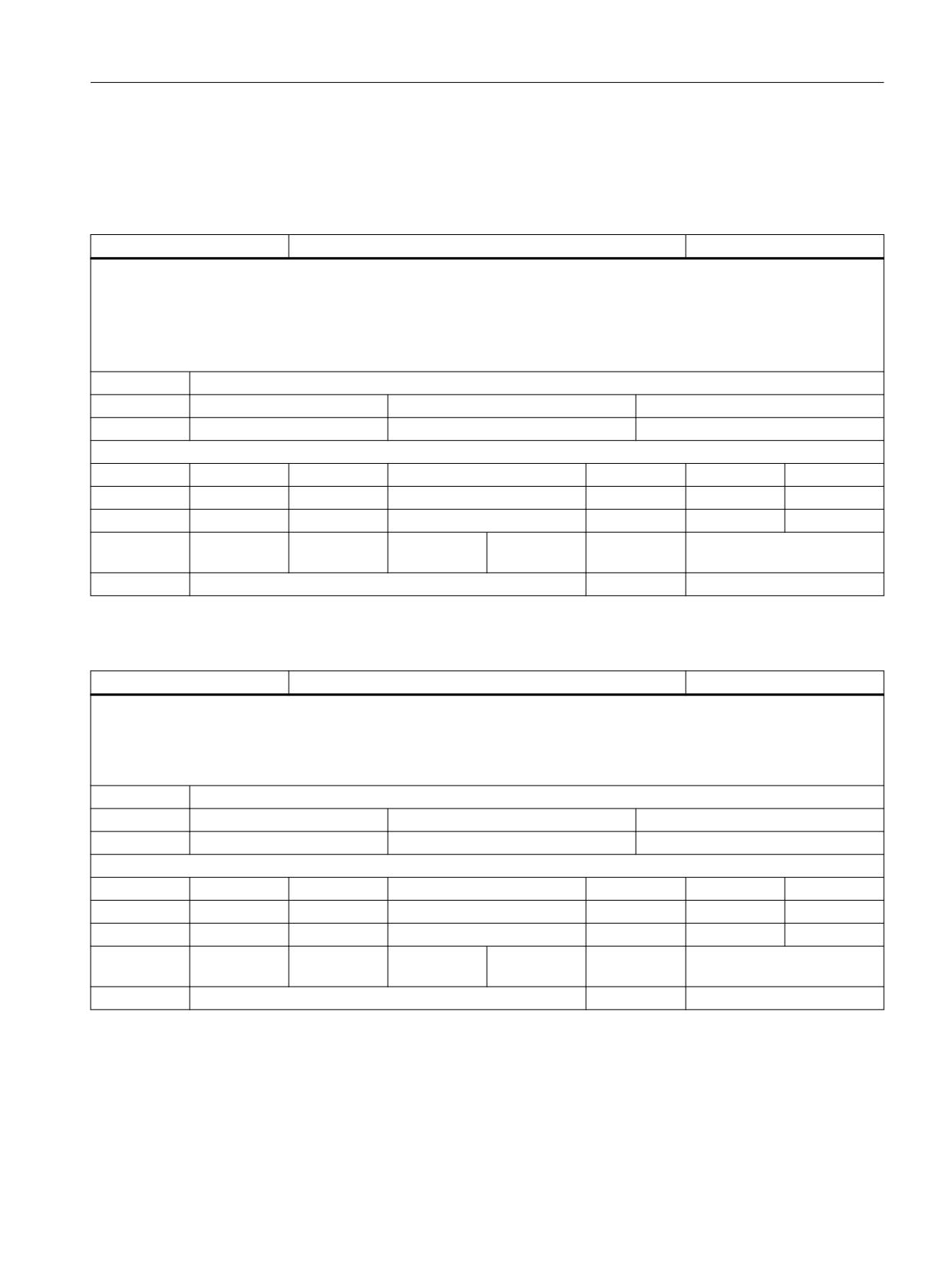
Structure of a system variables table
<Identifier[ Index 1, ... ]>
<short description>
<data type>
Description:
<descriptive text>
Index 1:
<description index 1>
Index 2:
<description index 2>
Index 3:
<description index 3>
Unit:
Default value
Minimum value
Maximum value
<unit>
<default value>
<minimum value>
<maximum value>
Properties of reading/writing:
PP
SA
PP / SA access level
NC variable
Access level
OEM-CC
Read:
<readability>
<readability>
<access level>
<NC variable>
<access lev-
<OEM CC>
el>
Write:
<writeability>
<writeability>
<access level>
<NC variable>
<access lev-
<OEM CC>
el>
Axis identifi-
GEO
CHAN
MACH
SPIN
Value deter-
<value determination proper-
er:
mination:
ty>
Search:
<search property>
Link:
<link property>
System variables
10
List Manual, 10/2020, 6FC5397-6AP40-6BA4
Introduction
2.3 Channel-specific and NC-global arithmetic parameters (R / RG)
2.3
Channel-specific and NC-global arithmetic parameters (R / RG)
Channel-specific arithmetic parameters (R)
R[ <index 1> ]
Channel-specific arithmetic parameters of type Real
DOUBLE
Description:
System variables Rn or R[n] are channel-specific arithmetic parameters of type REAL and are freely available to the user.
Programming in the part program: R<n> or R[<n>]
Programming in a synchronized action: $Rn or $R[<n>]
The channel-specific arithmetic parameters are stored retentively and can be read in and out via the data backup.
Index 1:
The maximum number of R parameters are specified in machine data MD28050 $MC_MM_NUM_R_PARAM.
Unit:
Default value
Minimum value
Maximum value
-
0.0
Max. negative DOUBLE value
Max. positive DOUBLE value
Properties of reading/writing:
PP
SA
PP / SA access level
NC variable
Access level
OEM_CC
Read:
X
X
7
X
7
X
Write:
X
X
7
X
7
X
Axis identifi-
-
-
-
-
Value deter-
channel-specific
er:
mination:
Search:
program-sensitive
Link:
No restrictions
Global arithmetic parameters (RG)
RG[ <index 1> ]
Global arithmetic parameters of type Real
DOUBLE
Description:
System variables RGn or RG[n] are NC-global arithmetic parameters of type REAL and are freely available to the user.
Programming in the part program: RG<n> or RG[<n>]
The NC-global arithmetic parameters are stored nonvolatilely and can be read in and out via the data backup.
Index 1:
The maximum number of R parameters are specified in machine data MD28050 $MC_MM_NUM_R_PARAM.
Unit:
Default value
Minimum value
Maximum value
-
0.0
Max. negative DOUBLE value
Max. positive DOUBLE value
Properties of reading/writing:
PP
SA
PP / SA access level
NC variable
Access level
OEM_CC
Read:
X
-
7
X
7
X
Write:
X
-
7
X
7
X
Axis identifi-
-
-
-
-
Value deter-
-
er:
mination:
Search:
program-sensitive
Link:
No restrictions
System variables
List Manual, 10/2020, 6FC5397-6AP40-6BA4
11
Introduction
2.4 Supplementary conditions
2.4
Supplementary conditions
Querying REAL and DOUBLE variables
We recommend programming querying of REAL or DOUBLE variables in NC programs and
synchronized actions as limit value evaluation.
Example: Querying the actual value of an axis $VA_IM to a specific value AXPOS ± 1*10-6
DEF REAL AXPOS = 123.456
IF ($VA_IM[<axis>] - 1ex-6) <= AXPOS <= ($VA_IM[<axis>] + 1ex-6)
ENDIF
System variables
12
List Manual, 10/2020, 6FC5397-6AP40-6BA4
List of system variables
3
3.1
Channel-specific synchronized action variables
$AC_MARKER [n]
User array variable of type Integer
INT
Description:
Array variable $AC_MARKER[n] is used to store application-related integer arithmetic results.
The variable is stored in DRAM or in SRAM depending on $MC_MM_BUFFERED_AC_MARKER. The array elements of the variable in volatile
memory (DRAM) are set to 0 on a Reset.
Index 1:
The dimension is defined via the MD $MC_MM_NUM_AC_MARKER.
Unit
Init value
Min
Max
-
0
-2147483648
2147483647
Read/Write properties:
TP
SA
TP/SA safety
NC-Variable
Safety
OEM-CC
Read:
runin stp
X
7
X
7
X
Write:
runin stp
X
7
-
0
X
Axis entry:
Overlap chan-
channel-specific
nel:
Scan mode:
Not classified
Link:
No restrictions
$AC_SYSTEM_MARKER [n]
System array variable of type Integer
INT
Description:
Array variable $AC_SYSTEM_MARKER[n] is used to store application-related integer arithmetic results. The variable is reserved for SIEMENS
applications.
The variable is stored in DRAM or in SRAM depending on $MC_MM_BUFFERED_AC_MARKER. The array elements of the variable in volatile
memory (DRAM) are set to 0 on a Reset.
Index 1:
The dimension is defined via the MD $MC_MM_NUM_AC_SYSTEM_MARKER.
Unit
Init value
Min
Max
-
0
-2147483648
2147483647
Read/Write properties:
TP
SA
TP/SA safety
NC-Variable
Safety
OEM-CC
Read:
runin stp
X
7
X
7
X
Write:
runin stp
X
7
-
0
X
Axis entry:
Overlap chan-
channel-specific
nel:
Scan mode:
Not classified
Link:
No restrictions
$AC_PARAM [n]
User array variable of type Real
DOUBLE
Description:
Array variable $AC_PARAM[n] is used to store application-related Real arithmetic results.
The variable is stored in DRAM or in SRAM depending on $MC_MM_BUFFERED_AC_PARAM. The array elements of the variable in volatile
memory (DRAM) are set to 0 on a Reset.
Index 1:
The dimension is defined via the MD $MC_MM_NUM_AC_PARAM.
Unit
Init value
Min
Max
-
0.0
-1.8E+308
1.8E+308
System variables
List Manual, 10/2020, 6FC5397-6AP40-6BA4
13
List of system variables
3.2 Channel-specific system variables
$AC_PARAM [n]
User array variable of type Real
DOUBLE
Read/Write properties:
TP
SA
TP/SA safety
NC-Variable
Safety
OEM-CC
Read:
runin stp
X
7
X
7
X
Write:
runin stp
X
7
-
0
X
Axis entry:
Overlap chan-
channel-specific
nel:
Scan mode:
Not classified
Link:
No restrictions
$AC_SYSTEM_PARAM [n]
System array variable of type Real
DOUBLE
Description:
Array variable $AC_SYSTEM_PARAM[n] is used to store application-related Real arithmetic results. The variable is reserved for SIEMENS appli-
cations.
The variable is stored in DRAM or in SRAM depending on $MC_MM_BUFFERED_AC_PARAM. The array elements of the variable in volatile
memory (DRAM) are set to 0 on a Reset.
Index 1:
The dimension is defined via the MD $MC_MM_NUM_AC_SYSTEM_PARAM.
Unit
Init value
Min
Max
-
0.0
-1.8E+308
1.8E+308
Read/Write properties:
TP
SA
TP/SA safety
NC-Variable
Safety
OEM-CC
Read:
runin stp
X
7
X
7
X
Write:
runin stp
X
7
-
0
X
Axis entry:
Overlap chan-
channel-specific
nel:
Scan mode:
Not classified
Link:
No restrictions
3.2
Channel-specific system variables
$P_UBFR
1st basic frame in the data management system
FRAME
Description:
Variable $P_UBFR is used to program the 1st basic frame in the data management system. G500, G54 .. G599 can be used to activate the
corresponding data management frame. The data management frames are stored in SRAM and can be read in and out using the data backup
feature. $P_UBFR is equivalent to $P_CHBFR[0].
Application:
$P_UBFR = ctrans(x,10) : crot(z,45)
$P_UBFR[y,tr] = 5
Unit
Init value
Min
Max
-
Read/Write properties:
TP
SA
TP/SA safety
NC-Variable
Safety
OEM-CC
Read:
X
-
7
-
0
-
Write:
X
-
7
-
0
-
Axis entry:
GEO
CHAN
MACH
SPIN
Overlap chan-
channel-specific
nel:
Scan mode:
Not classified
Link:
No restrictions
System variables
14
List Manual, 10/2020, 6FC5397-6AP40-6BA4
List of system variables
3.2 Channel-specific system variables
$P_SETFRAME
Active system frame for preset actual value memory
FRAME
Description:
Variable $P_SETFRAME is used to program the active system frame for preset actual value memory and scratching.
On a Reset, the activation of the system frame depends on the following machine data:
Bit0 in $MC_RESET_MODE_MASK
Bit0 in $MC_CHSFRAME_RESET_MASK
Unit
Init value
Min
Max
-
Read/Write properties:
TP
SA
TP/SA safety
NC-Variable
Safety
OEM-CC
Read:
X
-
7
X
7
-
Write:
X
-
7
-
0
-
Axis entry:
GEO
CHAN
MACH
SPIN
Overlap chan-
channel-specific
nel:
Scan mode:
Not classified
Link:
No restrictions
$P_EXTFRAME
Active system frame for external frame
FRAME
Description:
Variable $P_EXTFRAME is used to program the active system frame for the external work offset.
On a Reset, the activation of the system frame depends on the following machine data:
Bit0 in $MC_RESET_MODE_MASK
Bit1 in $MC_CHSFRAME_RESET_MASK
Unit
Init value
Min
Max
-
Read/Write properties:
TP
SA
TP/SA safety
NC-Variable
Safety
OEM-CC
Read:
X
-
7
X
7
-
Write:
X
-
7
-
0
-
Axis entry:
GEO
CHAN
MACH
SPIN
Overlap chan-
channel-specific
nel:
Scan mode:
Not classified
Link:
No restrictions
$P_PARTFRAME
Active system frame for toolholder
FRAME
Description:
Variable $P_PARTFRAME determines the active system frame for TCARR and PAROT.
On a Reset, the activation of the system frame depends on the following machine data:
Bit0 in $MC_RESET_MODE_MASK
$MC_GCODE_RESET_MODE[51]
$MC_GCODE_RESET_VALUES[51]
Unit
Init value
Min
Max
-
Read/Write properties:
TP
SA
TP/SA safety
NC-Variable
Safety
OEM-CC
Read:
X
-
7
X
7
-
Write:
X
-
7
-
0
-
System variables
List Manual, 10/2020, 6FC5397-6AP40-6BA4
15
List of system variables
3.2 Channel-specific system variables
$P_PARTFRAME
Active system frame for toolholder
FRAME
Axis entry:
GEO
CHAN
MACH
SPIN
Overlap chan-
channel-specific
nel:
Scan mode:
Not classified
Link:
No restrictions
$P_TOOLFRAME
Active system frame for TOROT
FRAME
Description:
Variable $P_TOOLFRAME determines the active system frame for TOROT and TOFRAME.
On a Reset, the activation of the system frame depends on the following machine data:
Bit0 in $MC_RESET_MODE_MASK
$MC_GCODE_RESET_MODE[52]
$MC_GCODE_RESET_VALUES[52]
Unit
Init value
Min
Max
-
Read/Write properties:
TP
SA
TP/SA safety
NC-Variable
Safety
OEM-CC
Read:
X
-
7
X
7
-
Write:
X
-
7
-
0
-
Axis entry:
GEO
CHAN
MACH
SPIN
Overlap chan-
channel-specific
nel:
Scan mode:
Not classified
Link:
No restrictions
$P_WPFRAME
Active system frame for the workpiece
FRAME
Description:
Variable $P_WPFRAME is used to program the active system frame for workpiece reference points.
On a Reset, the activation of the system frame depends on the following machine data:
Bit0 in $MC_RESET_MODE_MASK
Bit4 in $MC_CHSFRAME_RESET_MASK
Unit
Init value
Min
Max
-
Read/Write properties:
TP
SA
TP/SA safety
NC-Variable
Safety
OEM-CC
Read:
X
-
7
X
7
-
Write:
X
-
7
-
0
-
Axis entry:
GEO
CHAN
MACH
SPIN
Overlap chan-
channel-specific
nel:
Scan mode:
Not classified
Link:
No restrictions
$P_CYCFRAME
Active system frame for cycles
FRAME
Description:
Variable $P_CYCFRAME is used to program the active system frame for cycles.
On a Reset, the activation of the system frame depends on the following machine data:
Bit0 in $MC_RESET_MODE_MASK
Bit5 in $MC_CHSFRAME_RESET_MASK
Unit
Init value
Min
Max
-
Read/Write properties:
TP
SA
TP/SA safety
NC-Variable
Safety
OEM-CC
System variables
16
List Manual, 10/2020, 6FC5397-6AP40-6BA4
List of system variables
3.2 Channel-specific system variables
$P_CYCFRAME
Active system frame for cycles
FRAME
Read:
X
-
7
X
7
-
Write:
X
-
7
-
0
-
Axis entry:
GEO
CHAN
MACH
SPIN
Overlap chan-
channel-specific
nel:
Scan mode:
Not classified
Link:
No restrictions
$P_TRAFRAME
Active system frame for transformations
FRAME
Description:
Variable $P_TRAFRAME is used to program the active system frame for transformations. This system frame is configured as follows when a
transformation is selected with TRANSMIT or TRACYL:
$MN_FRAME_GEOAX_CHANGE_MODE = 1 oder 2
$MC_TRANSMIT_ROT_AX_FRAME_1 = 2
$MC_TRANSMIT_ROT_AX_FRAME_2 = 2
$MC_TRACYL_ROT_AX_FRAME_1 = 2
$MC_TRACYL_ROT_AX_FRAME_2 = 2
Unit
Init value
Min
Max
-
Read/Write properties:
TP
SA
TP/SA safety
NC-Variable
Safety
OEM-CC
Read:
X
-
7
X
7
-
Write:
X
-
7
-
0
-
Axis entry:
GEO
CHAN
MACH
SPIN
Overlap chan-
channel-specific
nel:
Scan mode:
Not classified
Link:
No restrictions
$P_CHBFRAME [n]
Active basic frame in channel
FRAME
Description:
Array variable $P_CHBFRAME[n] is used to program the nth active basic frame in the channel.
On a Reset, the activation of the basic frame depends on the following machine data:
Bit0 and Bit14 in $MC_RESET_MODE_MASK
$MC_CHBFRAME_RESET_MASK
Index 1:
The dimension is defined via $MC_MM_NUM_BASE_FRAMES.
Unit
Init value
Min
Max
-
Read/Write properties:
TP
SA
TP/SA safety
NC-Variable
Safety
OEM-CC
Read:
X
-
7
X
7
-
Write:
X
-
7
-
0
-
Axis entry:
GEO
CHAN
MACH
SPIN
Overlap chan-
channel-specific
nel:
Scan mode:
Not classified
Link:
No restrictions
System variables
List Manual, 10/2020, 6FC5397-6AP40-6BA4
17
List of system variables
3.2 Channel-specific system variables
$P_NCBFRAME [n]
Active global basic frame
FRAME
Description:
Array variable $P_NCBFRAME[n] is used to program the nth active global basic frame.
On a Reset, the activation of the basic frame depends on the following machine data:
Bit0 and Bit14 in $MC_RESET_MODE_MASK
$MN_NCBFRAME_RESET_MASK
Index 1:
The dimension is defined via $MN_MM_NUM_GLOBAL_BASE_FRAMES.
Unit
Init value
Min
Max
-
Read/Write properties:
TP
SA
TP/SA safety
NC-Variable
Safety
OEM-CC
Read:
X
-
7
X
7
-
Write:
X
-
7
-
0
-
Axis entry:
GEO
CHAN
MACH
SPIN
Overlap chan-
channel-specific
nel:
Scan mode:
Not classified
Link:
No restrictions
$P_ACTBFRAME
Active overall basic frame
FRAME
Description:
Variable $P_ACTBFRAME determines the active chained overall basic frame. This frame is produced by chaining together all valid (see
$P_NCBFRMASK) global basic frames and all valid (see $P_CHBFRMASK) basic frames in the channel. The overall basic frame is always recal-
culated when a basic frame is activated.
On a Reset, the activation of the basic frames depend on the following machine data:
Bit0 and Bit14 in $MC_RESET_MODE_MASK
$MN_NCBFRAME_RESET_MASK
$MC_CHBFRAME_RESET_MASK
Unit
Init value
Min
Max
-
Read/Write properties:
TP
SA
TP/SA safety
NC-Variable
Safety
OEM-CC
Read:
X
-
7
X
7
-
Write:
-
-
0
-
0
-
Axis entry:
GEO
CHAN
MACH
SPIN
Overlap chan-
channel-specific
nel:
Scan mode:
Not classified
Link:
No restrictions
$P_BFRAME
1. active basic frame in channel
FRAME
Description:
Variable $P_BFRAME is used to program the 1st active basic frame in the channel. The variable is equivalent to $P_CHBFRAME[0].
On a Reset, the activation of the basic frame depends on the following machine data:
Bit0 and Bit14 in $MC_RESET_MODE_MASK
$MC_CHBFRAME_RESET_MASK
Unit
Init value
Min
Max
-
Read/Write properties:
TP
SA
TP/SA safety
NC-Variable
Safety
OEM-CC
Read:
X
-
7
X
7
-
Write:
X
-
7
-
0
-
System variables
18
List Manual, 10/2020, 6FC5397-6AP40-6BA4
List of system variables
3.2 Channel-specific system variables
$P_BFRAME
1. active basic frame in channel
FRAME
Axis entry:
GEO
CHAN
MACH
SPIN
Overlap chan-
channel-specific
nel:
Scan mode:
Not classified
Link:
No restrictions
$P_IFRAME
Active settable frame
FRAME
Description:
Variable $P_IFRAME is used to program the active settable frame. A settable data management frame $P_UIFR[n] becomes the active settable
frame on execution of G500, G54 to G599.
On a Reset, the activation of the settable frame depends on the following machine data:
Bit0 in $MC_RESET_MODE_MASK
$MC_GCODE_RESET_MODE[7]
$MC_GCODE_RESET_VALUES[7]
Unit
Init value
Min
Max
-
Read/Write properties:
TP
SA
TP/SA safety
NC-Variable
Safety
OEM-CC
Read:
X
-
7
X
7
-
Write:
X
-
7
-
0
-
Axis entry:
GEO
CHAN
MACH
SPIN
Overlap chan-
channel-specific
nel:
Scan mode:
Not classified
Link:
No restrictions
$P_PFRAME
Programmable frame
FRAME
Description:
Variable $P_PFRAME is used to program the active programmable frame.
The programmable frame is retained on a Reset when the following setting is configured:
$MC_PFRAME_RESET_MODE = 1
Unit
Init value
Min
Max
-
Read/Write properties:
TP
SA
TP/SA safety
NC-Variable
Safety
OEM-CC
Read:
X
-
7
X
7
-
Write:
X
-
7
-
0
-
Axis entry:
GEO
CHAN
MACH
SPIN
Overlap chan-
channel-specific
nel:
Scan mode:
Not classified
Link:
No restrictions
$P_ACTFRAME
Active overall frame
FRAME
Description:
The variable $P_ACTFRAME determines the active chained total frame. The active total frame is calculated using the following formula:
$P_ACTFRAME = $P_PARTFRAME : $P_SETFRAME : $P_EXTFRAME : $P_ISO1FRAME : $P_ISO2FRAME : $P_ISO3FRAME : $P_ACTBFRAME :
$P_IFRAME : $P_GFRAME : $P_TOOLFRAME : $P_WPFRAME : $P_TRAFRAME : $P_PFRAME : $P_ISO4FRAME : $P_CYCFRAME
The total frame is recalculated each time a frame belonging to the frame chain is activated and upon a reset.
Unit
Init value
Min
Max
-
Read/Write properties:
TP
SA
TP/SA safety
NC-Variable
Safety
OEM-CC
Read:
X
-
7
X
7
-
System variables
List Manual, 10/2020, 6FC5397-6AP40-6BA4
19
List of system variables
3.2 Channel-specific system variables
$P_ACTFRAME
Active overall frame
FRAME
Write:
-
-
0
-
0
-
Axis entry:
GEO
CHAN
MACH
SPIN
Overlap chan-
channel-specific
nel:
Scan mode:
Not classified
Link:
No restrictions
$P_UIFRNUM
Number of active settable frames
INT
Description:
Variable $P_UIFRNUM is used to determine the number of the active settable frame. A settable data management frame $P_UIFR[n] becomes
the active settable frame on execution of G500, G54 to G599.
G500: $P_UIFRNUM = 0
G54: $P_UIFRNUM = 1
G599: $P_UIFRNUM = 99
On a Reset, the activation of the settable frame depends on the following machine data:
Bit0 in $MC_RESET_MODE_MASK
$MC_GCODE_RESET_MODE[7]
$MC_GCODE_RESET_VALUES[7]
Unit
Init value
Min
Max
-
0
0
99
Read/Write properties:
TP
SA
TP/SA safety
NC-Variable
Safety
OEM-CC
Read:
X
-
7
-
0
-
Write:
-
-
0
-
0
-
Axis entry:
Overlap chan-
channel-specific
nel:
Scan mode:
Not classified
Link:
No restrictions
$P_NCBFRMASK
Global basic frame mask
INT
Description:
Variable $P_NCBFRMASK is used to define the NCU-global basic frame included in the calculation of the overall basic frame $P_ACTBFRAME.
The variable is implemented in the form of a bit mask in which the global basic frames can be selected. On a Reset, the mask is initialized by
$MN_NCBFRAME_RESET_MASK.
Unit
Init value
Min
Max
-
0
0
0xFFFF
Read/Write properties:
TP
SA
TP/SA safety
NC-Variable
Safety
OEM-CC
Read:
X
-
7
-
0
-
Write:
X
-
7
-
0
-
Axis entry:
Overlap chan-
channel-specific
nel:
Scan mode:
Not classified
Link:
No restrictions
$P_CHBFRMASK
Basic frame mask in the channel
INT
Description:
Variable $P_CHBFRMASK is used to define the channel-specific basic frame included in the calculation of the overall basic frame $P_ACTB-
FRAME. The variable is implemented in the form of a bit mask in which the basic frames can be selected. On a Reset, the mask is initialized by
$MC_CHBFRAME_RESET_MASK.
Unit
Init value
Min
Max
-
0
0
0xFFFF
System variables
20
List Manual, 10/2020, 6FC5397-6AP40-6BA4
List of system variables
3.2 Channel-specific system variables
$P_CHBFRMASK
Basic frame mask in the channel
INT
Read/Write properties:
TP
SA
TP/SA safety
NC-Variable
Safety
OEM-CC
Read:
X
-
7
-
0
-
Write:
X
-
7
-
0
-
Axis entry:
Overlap chan-
channel-specific
nel:
Scan mode:
Not classified
Link:
No restrictions
$P_CHSFRMASK
System frame mask
INT
Description:
Variable $P_CHSFRMASK is used to define the channel-specific system frame included in the calculation of the overall frame $P_ACTFRAME. The
variable is implemented in the form of a bit mask in which the system frames can be selected. On a Reset, the mask is initialized by
$MC_CHSFRAME_RESET_MASK.
Unit
Init value
Min
Max
-
0
0
0x7FF
Read/Write properties:
TP
SA
TP/SA safety
NC-Variable
Safety
OEM-CC
Read:
X
-
7
-
0
-
Write:
X
-
7
-
0
-
Axis entry:
Overlap chan-
channel-specific
nel:
Scan mode:
Not classified
Link:
No restrictions
$P_AD [36]
Active tool offsets
DOUBLE
Description:
$P_AD[n]
Active tool offsets
n: Parameter numbers 1 - 36
n = 1-25 $TC_DP1 to $TC_DP25
n = 26 $TC_DPCE Number of the cutting edge (function: Unique D number)
n = 27 $TC_DPH H number of the cutting edge (function: ISO mode)
n = 28 $TC_DPV Tool orientation (function: Tool orientation)
n = 29 $TC_DPV3 Component 1 of the tool orientation (function: Tool orientation)
n = 30 $TC_DPV4 Component 2 of the tool orientation (function: Tool orientation)
n = 31 $TC_DPV5 Component 3 of the tool orientation (function: Tool orientation)
n = 32 $TC_DPVN3 Normal vector component 1 (function: Tool orientation)
n = 33 $TC_DPVN4 Normal vector component 2 (function: Tool orientation)
n = 34 $TC_DPVN5 Normal vector component 3 (function: Tool orientation)
n = 35 $TC_DPNT Number of teeth on the cutting edge
n = 36 $TC_DPROT Base angle of rotation of the cutting edge
An alarm is issued if a compensation parameter belongs to a function that is not active.
Index 1:
n: Parameter numbers 1 - 36
Unit
Init value
Min
Max
-
0.0
-1.8E+308
1.8E+308
Read/Write properties:
TP
SA
TP/SA safety
NC-Variable
Safety
OEM-CC
Read:
X
-
7
-
0
-
Write:
X
-
7
-
0
-
System variables
List Manual, 10/2020, 6FC5397-6AP40-6BA4
21
List of system variables
3.2 Channel-specific system variables
$P_AD [36]
Active tool offsets
DOUBLE
Axis entry:
Overlap chan-
channel-specific
nel:
Scan mode:
Program sensitive
Link:
No restrictions
$P_ADT [36]
Active tool offsets transformed
DOUBLE
Description:
$P_ADT[n]
Active tool offsets transformed
n: Parameter numbers 1 - 36
n = 1-25 $TC_DP1 to $TC_DP25
n = 26 $TC_DPCE Number of the cutting edge (function: Unique D number)
n = 27 $TC_DPH H number of the cutting edge (function: ISO mode)
n = 28 $TC_DPV Tool orientation (function: Tool orientation)
n = 29 $TC_DPV3 Component 1 of the tool orientation (function: Tool orientation)
n = 30 $TC_DPV4 Component 2 of the tool orientation (function: Tool orientation)
n = 31 $TC_DPV5 Component 3 of the tool orientation (function: Tool orientation)
n = 32 $TC_DPVN3 Normal vector component 1 (function: Tool orientation)
n = 33 $TC_DPVN4 Normal vector component 2 (function: Tool orientation)
n = 34 $TC_DPVN5 Normal vector component 3 (function: Tool orientation)
n = 35 $TC_DPNT Number of teeth on the cutting edge
n = 36 $TC_DPROT Base angle of rotation of the cutting edge
An alarm is issued if a compensation parameter belongs to a function that is not active.
Index 1:
n: Parameter numbers 1 - 36
Unit
Init value
Min
Max
-
0.0
-1.8E+308
1.8E+308
Read/Write properties:
TP
SA
TP/SA safety
NC-Variable
Safety
OEM-CC
Read:
X
-
7
-
0
-
Write:
X
-
7
-
0
-
Axis entry:
Overlap chan-
channel-specific
nel:
Scan mode:
Program sensitive
Link:
No restrictions
$P_DLNO
-
INT
Description:
$P_DLNO
Active additive offset number DL=0 - DL='max.'; 'max'= value of $MN_MM_MAX_SUMCORR_PER_CUTTEDGE
Unit
Init value
Min
Max
-
0
-2147483648
2147483647
Read/Write properties:
TP
SA
TP/SA safety
NC-Variable
Safety
OEM-CC
Read:
X
-
7
-
0
-
Write:
-
-
0
-
0
-
Axis entry:
Overlap chan-
channel-specific
nel:
Scan mode:
Not classified
Link:
No restrictions
System variables
22
List Manual, 10/2020, 6FC5397-6AP40-6BA4
List of system variables
3.2 Channel-specific system variables
$P_TOOL
-
INT
Description:
$P_TOOL
Active tool cutting edge D0 - D'max.'; 'max'= value of $MN_MM_MAX_CUTTING_EDGE_NO
Unit
Init value
Min
Max
-
0
-2147483648
2147483647
Read/Write properties:
TP
SA
TP/SA safety
NC-Variable
Safety
OEM-CC
Read:
X
-
7
-
0
-
Write:
-
-
0
-
0
-
Axis entry:
Overlap chan-
channel-specific
nel:
Scan mode:
Not classified
Link:
No restrictions
$P_TOOLNO
-
INT
Description:
$P_TOOLNO
Active tool number T0 - T32000; T can be an 8-digit number when 'flat D number' function is active
This command should not generally be used when magazine management is active.
When magazine management is active, GETEXET should be used instead.
(T number programming always works reliably when $MC_CUTTING_EDGE_DEFAULT=-1, or> 0.
In cases where $MC_CUTTING_EDGE_DEFAULT=0, or =-2, T number read errors can occur.
The T number mechanism is also reliable if it is programmed after D> 0.
Notice: Particularly with a setting of $MC_CUTTING_EDGE_DEFAULT=-2, $P_TOOLNO (the T no. of the active tool with which the currently
active D offset has been calculated) and GETEXET (the changed tool) can return different T numbers.
->see also $P_MTHSDC and the documentation relating to the subject of multiple toolholders/spindles.
Unit
Init value
Min
Max
-
0
0
32000
Read/Write properties:
TP
SA
TP/SA safety
NC-Variable
Safety
OEM-CC
Read:
X
-
7
-
0
-
Write:
-
-
0
-
0
-
Axis entry:
Overlap chan-
channel-specific
nel:
Scan mode:
Not classified
Link:
No restrictions
$P_TOOLP
-
INT
Description:
$P_TOOLP
Last programmed tool number T0 - T32000 (in operation without magazine management).
This command cannot be used when magazine management is active.
When magazine management is active, GETSELT must be used instead.
If the function 'T alarm delay after M06' is active, the
result T number = -1 if the preceding T address has been programmed incorrectly.
Unit
Init value
Min
Max
-
0
0
32000
Read/Write properties:
System variables
List Manual, 10/2020, 6FC5397-6AP40-6BA4
23
List of system variables
3.2 Channel-specific system variables
$P_TOOLP
-
INT
TP
SA
TP/SA safety
NC-Variable
Safety
OEM-CC
Read:
X
-
7
-
0
-
Write:
-
-
0
-
0
-
Axis entry:
Overlap chan-
channel-specific
nel:
Scan mode:
Program sensitive
Link:
No restrictions
$P_TOOLL [3]
$P_TOOLL[1] to $P_TOOLL[3] map $TC_DP3[] to
DOUBLE
$TC_DP5[].
Description:
$P_TOOLL[n]
$P_TOOLL[1] to $P_TOOLL[3] correspond to the values in $TC_DP3[] to $TC_DP5[], including active tool offsets, independently of the plane
selection and setting data such as $SC_TOOL_LENGTH_CONST etc.
Index 1:
n: Length 1 - 3
Unit
Init value
Min
Max
mm
0.0
-1.8E+308
1.8E+308
Read/Write properties:
TP
SA
TP/SA safety
NC-Variable
Safety
OEM-CC
Read:
X
-
7
-
0
-
Write:
-
-
0
-
0
-
Axis entry:
Overlap chan-
channel-specific
nel:
Scan mode:
Not classified
Link:
No restrictions
$P_TOOLO [3]
Active tool orientation
DOUBLE
Description:
$P_TOOLO[n]
Active tool orientation
Index 1:
n: Components 1 - 3
Unit
Init value
Min
Max
-
0.0
-1.8E+308
1.8E+308
Read/Write properties:
TP
SA
TP/SA safety
NC-Variable
Safety
OEM-CC
Read:
X
-
7
-
0
-
Write:
-
-
0
-
0
-
Axis entry:
Overlap chan-
channel-specific
nel:
Scan mode:
Not classified
Link:
No restrictions
$AC_TOOLO_ACT [3]
Active setpoint orientation
DOUBLE
Description:
$AC_TOOLO_ACT[n]
Active command orientation
Index 1:
n: Components 1 - 3
Unit
Init value
Min
Max
-
0.0
-1.0
1.0
Read/Write properties:
TP
SA
TP/SA safety
NC-Variable
Safety
OEM-CC
System variables
24
List Manual, 10/2020, 6FC5397-6AP40-6BA4
List of system variables
3.2 Channel-specific system variables
$AC_TOOLO_ACT [3]
Active setpoint orientation
DOUBLE
Read:
runin stp
X
7
X
7
X
Write:
-
-
0
-
0
-
Axis entry:
Overlap chan-
channel-specific
nel:
Scan mode:
Not classified
Link:
No restrictions
$AC_TOOLO_END [3]
Final orientation of the active block
DOUBLE
Description:
$AC_TOOLO_END[n]
End orientation of active block
Index 1:
n: Components 1 - 3
Unit
Init value
Min
Max
-
0.0
-1.0
1.0
Read/Write properties:
TP
SA
TP/SA safety
NC-Variable
Safety
OEM-CC
Read:
runin stp
X
7
X
7
X
Write:
-
-
0
-
0
-
Axis entry:
Overlap chan-
channel-specific
nel:
Scan mode:
Not classified
Link:
No restrictions
$AC_TOOLO_DIFF
Remaining angle to the orientation in the active block
DOUBLE
Description:
$AC_TOOLO_DIFF
Remaining angle of tool orientation in active block
Unit
Init value
Min
Max
deg.
0.0
0.0
360.0
Read/Write properties:
TP
SA
TP/SA safety
NC-Variable
Safety
OEM-CC
Read:
runin stp
X
7
X
7
X
Write:
-
-
0
-
0
-
Axis entry:
Overlap chan-
channel-specific
nel:
Scan mode:
Not classified
Link:
No restrictions
$VC_TOOLO [3]
Actual orientation
DOUBLE
Description:
$VC_TOOLO[n]
Actual orientation
Index 1:
n: Components 1 - 3
Unit
Init value
Min
Max
-
0.0
-1.0
1.0
Read/Write properties:
TP
SA
TP/SA safety
NC-Variable
Safety
OEM-CC
Read:
runin stp
X
7
X
7
X
Write:
-
-
0
-
0
-
System variables
List Manual, 10/2020, 6FC5397-6AP40-6BA4
25
List of system variables
3.2 Channel-specific system variables
$VC_TOOLO [3]
Actual orientation
DOUBLE
Axis entry:
Overlap chan-
channel-specific
nel:
Scan mode:
Not classified
Link:
No restrictions
$VC_TOOLO_DIFF
Angle between set and actual orientation
DOUBLE
Description:
$VC_TOOLO_DIFF
Angle between command and actual orientation
Unit
Init value
Min
Max
deg.
0.0
0.0
180.0
Read/Write properties:
TP
SA
TP/SA safety
NC-Variable
Safety
OEM-CC
Read:
runin stp
X
7
X
7
X
Write:
-
-
0
-
0
-
Axis entry:
Overlap chan-
channel-specific
nel:
Scan mode:
Not classified
Link:
No restrictions
$VC_TOOLO_STAT
Status of the calculation of the actual orientation
INT
Description:
$VC_TOOLO_STAT
Status of calculation of actual orientation
Unit
Init value
Min
Max
-
0
-1
2147483647
Read/Write properties:
TP
SA
TP/SA safety
NC-Variable
Safety
OEM-CC
Read:
runin stp
X
7
X
7
X
Write:
-
-
0
-
0
-
Axis entry:
Overlap chan-
channel-specific
nel:
Scan mode:
Not classified
Link:
No restrictions
$P_TC
Active toolholder
INT
Description:
$P_TC
Active toolholder
Unit
Init value
Min
Max
-
0
-2147483648
2147483647
Read/Write properties:
TP
SA
TP/SA safety
NC-Variable
Safety
OEM-CC
Read:
X
-
7
-
0
-
Write:
-
-
0
-
0
-
Axis entry:
Overlap chan-
channel-specific
nel:
Scan mode:
Not classified
Link:
No restrictions
System variables
26
List Manual, 10/2020, 6FC5397-6AP40-6BA4
List of system variables
3.2 Channel-specific system variables
$AC_TC
Active tool carrier
INT
Description:
$AC_TC
Active toolholder
Unit
Init value
Min
Max
-
0
-2147483648
2147483647
Read/Write properties:
TP
SA
TP/SA safety
NC-Variable
Safety
OEM-CC
Read:
runin stp
X
7
X
7
X
Write:
-
-
0
-
0
-
Axis entry:
Overlap chan-
channel-specific
nel:
Scan mode:
Not classified
Link:
No restrictions
$P_TCNUM
Number of tool carriers available in the channel
INT
Description:
$P_TCNUM
Number of available toolholders in the channel
Unit
Init value
Min
Max
-
0
-2147483648
2147483647
Read/Write properties:
TP
SA
TP/SA safety
NC-Variable
Safety
OEM-CC
Read:
X
-
7
-
0
-
Write:
-
-
0
-
0
-
Axis entry:
Overlap chan-
channel-specific
nel:
Scan mode:
Not classified
Link:
No restrictions
$P_TCANG [2]
Active angle of a tool carrier axis
DOUBLE
Description:
$P_TCANG[n]
Active angle of a toolholder axis
Index 1:
n: Angle 1 - 2
Unit
Init value
Min
Max
-
0.0
-1.8E+308
1.8E+308
Read/Write properties:
TP
SA
TP/SA safety
NC-Variable
Safety
OEM-CC
Read:
X
-
7
-
0
-
Write:
-
-
0
-
0
-
Axis entry:
Overlap chan-
channel-specific
nel:
Scan mode:
Not classified
Link:
No restrictions
System variables
List Manual, 10/2020, 6FC5397-6AP40-6BA4
27
List of system variables
3.2 Channel-specific system variables
$P_TCDIFF [2]
Angle difference with Hirth teeth
DOUBLE
Description:
$P_TCDIFF[n]
Difference between calculated and used angle of a toolholder axis
with angle incrementation (Hirth tooth system)
Index 1:
n: Angle 1 - 2
Unit
Init value
Min
Max
-
0.0
-1.8E+308
1.8E+308
Read/Write properties:
TP
SA
TP/SA safety
NC-Variable
Safety
OEM-CC
Read:
X
-
7
-
0
-
Write:
-
-
0
-
0
-
Axis entry:
Overlap chan-
channel-specific
nel:
Scan mode:
Not classified
Link:
No restrictions
$P_TCSOL
Solution number for tool carrier
INT
Description:
$P_TCSOL
Number of solutions when the angle of the axis of rotation of an orientable tool carrier is defined from a frame
In the case of 0 to 2 solutions, the relevant value is returned.
The return value is 3 when the number of solutions is infinite.
If the angles are specified (TCOABS), the number of solutions is always 1.
Unit
Init value
Min
Max
-
0
-2147483648
3
Read/Write properties:
TP
SA
TP/SA safety
NC-Variable
Safety
OEM-CC
Read:
X
-
7
-
0
-
Write:
-
-
0
-
0
-
Axis entry:
Overlap chan-
channel-specific
nel:
Scan mode:
Not classified
Link:
No restrictions
System variables
28
List Manual, 10/2020, 6FC5397-6AP40-6BA4
List of system variables
3.2 Channel-specific system variables
$P_TCSTAT
Status of an orientable tool carrier.
INT
Description:
$P_TCSTAT
Specifies the status of an orientatable toolholder.
The variable is bit-coded with the following bit meanings:
0x1
The first axis of rotation exists
0x2
The second axis of rotation exists
0x4
The angles used in the calculation are acquired from an orientation in the frame direction
0x8
The angles used in the calculation have been specified absolutely
0x10
The polar axis angle is uncertain with the toolholder orientated in the frame direction
0x1000
Only the tool is rotatable (kinematic type T)
0x2000
Only the workpiece is rotatable (kinetmatic type P)
0x4000
Tool and workpiece are rotatable (kinematic type M)
The bits specified here are not currently assigned.
Unit
Init value
Min
Max
-
0
-2147483648
2147483647
Read/Write properties:
TP
SA
TP/SA safety
NC-Variable
Safety
OEM-CC
Read:
X
-
7
-
0
-
Write:
-
-
0
-
0
-
Axis entry:
Overlap chan-
channel-specific
nel:
Scan mode:
Not classified
Link:
No restrictions
$P_TOOLR
Active tool radius
DOUBLE
Description:
$P_TOOLR
Active tool radius (total)
Unit
Init value
Min
Max
mm
0.0
-1.8E+308
1.8E+308
Read/Write properties:
TP
SA
TP/SA safety
NC-Variable
Safety
OEM-CC
Read:
X
-
7
-
0
-
Write:
-
-
0
-
0
-
Axis entry:
Overlap chan-
channel-specific
nel:
Scan mode:
Not classified
Link:
No restrictions
$P_TOOLND [32000]
Number of edges of tool T
INT
Description:
$P_TOOLND[t]
Number of tool edges of tool t
Index 1:
t: T number 1 - SLMAXTOOLNUMBER
Unit
Init value
Min
Max
-
0
-2147483648
2147483647
Read/Write properties:
TP
SA
TP/SA safety
NC-Variable
Safety
OEM-CC
System variables
List Manual, 10/2020, 6FC5397-6AP40-6BA4
29
List of system variables
3.2 Channel-specific system variables
$P_TOOLND [32000]
Number of edges of tool T
INT
Read:
X
-
7
-
0
-
Write:
-
-
0
-
0
-
Axis entry:
Overlap chan-
channel-specific
nel:
Scan mode:
Not classified
Link:
No restrictions
$P_TOOLEXIST [32000]
Tool exists with T no. t
BOOL
Description:
$P_TOOLEXIST[t]
Does the tool with T no. t exist
Index 1:
t: T number 1 - SLMAXTOOLNUMBER
Unit
Init value
Min
Max
-
FALSE
FALSE
TRUE
Read/Write properties:
TP
SA
TP/SA safety
NC-Variable
Safety
OEM-CC
Read:
X
-
7
-
0
-
Write:
-
-
0
-
0
-
Axis entry:
Overlap chan-
channel-specific
nel:
Scan mode:
Program sensitive
Link:
No restrictions
$P_D
Programmed D number (ISO2.1 mode)
INT
Description:
$P_D
Programmed D number in ISO_2.1 language mode
The D number is the tool offset number in ISO mode 2.1 (millling). If no tool offset is active, the value 0 is output.
The tool offset can be selected with D or H. However, this variable only ever contains the D value.
Unit
Init value
Min
Max
-
0
-2147483648
2147483647
Read/Write properties:
TP
SA
TP/SA safety
NC-Variable
Safety
OEM-CC
Read:
X
-
7
X
7
-
Write:
-
-
0
-
0
-
Axis entry:
Overlap chan-
channel-specific
nel:
Scan mode:
Program sensitive
Link:
No restrictions
$P_H
Programmed H number (ISO2.1 milling)
INT
Description:
$P_H
Programmed H number in ISO_2.1 language mode
The H number is the tool offset number in ISO mode 2.1 (millling). If no tool offset is active, the value 0 is output.
The tool offset can be selected with D or H. However, this variable only ever contains the H value.
Unit
Init value
Min
Max
-
0
-2147483648
2147483647
Read/Write properties:
TP
SA
TP/SA safety
NC-Variable
Safety
OEM-CC
System variables
30
List Manual, 10/2020, 6FC5397-6AP40-6BA4
List of system variables
3.2 Channel-specific system variables
$P_H
Programmed H number (ISO2.1 milling)
INT
Read:
X
-
7
X
7
-
Write:
-
-
0
-
0
-
Axis entry:
Overlap chan-
channel-specific
nel:
Scan mode:
Program sensitive
Link:
No restrictions
$A_TOOLMN [32000]
-
INT
Description:
$A_TOOLMN[t]
Magazine number of tool t
Index 1:
t: T number 1 - SLMAXTOOLNUMBER
Unit
Init value
Min
Max
-
0
-2147483648
2147483647
Read/Write properties:
TP
SA
TP/SA safety
NC-Variable
Safety
OEM-CC
Read:
X
X
7
X
7
X
Write:
-
-
0
-
0
-
Axis entry:
Overlap chan-
channel-specific
nel:
Scan mode:
Not classified
Link:
No restrictions
$A_TOOLMLN [32000]
-
INT
Description:
$A_TOOLMLN[t]
Magazine location number of tool t
Index 1:
t: T number 1 - SLMAXTOOLNUMBER
Unit
Init value
Min
Max
-
0
-2147483648
2147483647
Read/Write properties:
TP
SA
TP/SA safety
NC-Variable
Safety
OEM-CC
Read:
X
X
7
X
7
X
Write:
-
-
0
-
0
-
Axis entry:
Overlap chan-
channel-specific
nel:
Scan mode:
Not classified
Link:
No restrictions
$A_MYMN [32000]
-
INT
Description:
$A_MYMN[t]
Number of home magazine of tool with T no. t.
(A magazine becomes the home magazine of the tool if the tool is being loaded onto a
magazine location of kind 1 ($TC_MPP1=1).)
Resulting value = 0 = tool is not loaded (if $A_TOOLMN> 0, then manual tool).
Resulting value = -1 = tool management is not active
Resulting value = -2 = tool with T no. t does not exist.
Index 1:
t: T number 1 - SLMAXTOOLNUMBER
Unit
Init value
Min
Max
System variables
List Manual, 10/2020, 6FC5397-6AP40-6BA4
31
List of system variables
3.2 Channel-specific system variables
$A_MYMN [32000]
-
INT
-
0
-2147483648
2147483647
Read/Write properties:
TP
SA
TP/SA safety
NC-Variable
Safety
OEM-CC
Read:
X
X
7
X
7
X
Write:
-
-
0
-
0
-
Axis entry:
Overlap chan-
channel-specific
nel:
Scan mode:
Not classified
Link:
No restrictions
$A_MYMLN [32000]
-
INT
Description:
$A_MYMLN[t]
Number of the home magazine location of the tool with T no. t.
(A magazine location becomes the home magazine location of a tool if the tool is being loaded onto a magazine location of
kind 1 ($TC_MPP1=1).)
Resulting value = 0 = tool is not loaded (if $A_TOOLMLN> 0, then manual tool).
Resulting value = -1 = tool management is not active
Resulting value = -2 = tool with T no. t does not exist.
Index 1:
t: T number 1 - SLMAXTOOLNUMBER
Unit
Init value
Min
Max
-
0
-2147483648
2147483647
Read/Write properties:
TP
SA
TP/SA safety
NC-Variable
Safety
OEM-CC
Read:
X
X
7
X
7
X
Write:
-
-
0
-
0
-
Axis entry:
Overlap chan-
channel-specific
nel:
Scan mode:
Not classified
Link:
No restrictions
$A_MONIFACT
-
DOUBLE
Description:
$A_MONIFACT
Factor for tool life monitoring
Unit
Init value
Min
Max
-
0.0
-1.8E+308
1.8E+308
Read/Write properties:
TP
SA
TP/SA safety
NC-Variable
Safety
OEM-CC
Read:
X
X
7
X
7
X
Write:
runin stp
X
7
-
0
X
Axis entry:
Overlap chan-
channel-specific
nel:
Scan mode:
Not classified
Link:
No restrictions
System variables
32
List Manual, 10/2020, 6FC5397-6AP40-6BA4
List of system variables
3.2 Channel-specific system variables
$P_TOOLNG
Number of defined tool groups
INT
Description:
$P_TOOLNG
Number of defined tool groups assigned to the channel
OPI block type= TM
Unit
Init value
Min
Max
-
0
-2147483648
2147483647
Read/Write properties:
TP
SA
TP/SA safety
NC-Variable
Safety
OEM-CC
Read:
X
-
7
X
7
-
Write:
-
-
0
-
0
-
Axis entry:
Overlap chan-
channel-specific
nel:
Scan mode:
Not classified
Link:
No restrictions
$P_TOOLNT
Number of defined tools
INT
Description:
$P_TOOLNT
Number of defined tools assigned to the channel
OPI block type= TV
Unit
Init value
Min
Max
-
0
-2147483648
2147483647
Read/Write properties:
TP
SA
TP/SA safety
NC-Variable
Safety
OEM-CC
Read:
X
-
7
X
7
-
Write:
-
-
0
-
0
-
Axis entry:
Overlap chan-
channel-specific
nel:
Scan mode:
Not classified
Link:
No restrictions
$P_TOOLT [1500]
Tool number
INT
Description:
$P_TOOLT[i]
ith tool number T
OPI block type= TV
Index 1:
i= 1,..., $P_TOOLNT
Unit
Init value
Min
Max
-
0
-2147483648
2147483647
Read/Write properties:
TP
SA
TP/SA safety
NC-Variable
Safety
OEM-CC
Read:
X
-
7
X
7
-
Write:
-
-
0
-
0
-
Axis entry:
Overlap chan-
channel-specific
nel:
Scan mode:
Not classified
Link:
No restrictions
System variables
List Manual, 10/2020, 6FC5397-6AP40-6BA4
33
List of system variables
3.2 Channel-specific system variables
$P_TOOLD [32000,12]
D no. of tool T
INT
Description:
$P_TOOLD[t,i]
ith D no. of tool with T no. t; i=1,2...
If t is the value of an undefined tool, -2 is returned
If i is a value outside the permissible range, 0 is returned
OPI block type= TO
Index 1:
t = 1,
, SLMAXTOOLNUMBER
Index 2:
i = 1,
, $P_TOOLND
Unit
Init value
Min
Max
-
0
-2147483648
2147483647
Read/Write properties:
TP
SA
TP/SA safety
NC-Variable
Safety
OEM-CC
Read:
X
-
7
X
7
-
Write:
-
-
0
-
0
-
Axis entry:
Overlap chan-
channel-specific
nel:
Scan mode:
Not classified
Link:
No restrictions
$P_USEKT
Tool selection screen
INT
Description:
$P_USEKT (= USE Kind of Tool)
Is a bit-coded value
All tools whose parameter $TC_TP11 has set one of the bits of $P_USEKT
are available for the following tool changes. The value 'zero' has the equivalent content of
'all bits are set'
OPI block= C/S
Unit
Init value
Min
Max
-
0
-2147483648
2147483647
Read/Write properties:
TP
SA
TP/SA safety
NC-Variable
Safety
OEM-CC
Read:
X
-
7
X
7
-
Write:
X
-
7
-
0
-
Axis entry:
Overlap chan-
channel-specific
nel:
Scan mode:
Not classified
Link:
No restrictions
System variables
34
List Manual, 10/2020, 6FC5397-6AP40-6BA4
List of system variables
3.2 Channel-specific system variables
$P_TOOLNDL [32000,32000]
Number of DL offsets
INT
Description:
$P_TOOLNDL[t,d]
Number of DL offsets of D offset specified by T no. t and D no. d
>0 Number of DL offsets
0 No DL offset for this D offset
-1 Additive offset function not active
-2 t is the value of an undefined tool
-3
d is the value of an undefined D offset
OPI block type= TOS; TOE
Index 1:
t = 1,
, SLMAXTOOLNUMBER
Index 2:
d = 1,
, SLMAXCUTTINGEDGENUMBER
Unit
Init value
Min
Max
-
0
-2147483648
2147483647
Read/Write properties:
TP
SA
TP/SA safety
NC-Variable
Safety
OEM-CC
Read:
X
-
7
X
7
-
Write:
-
-
0
-
0
-
Axis entry:
Overlap chan-
channel-specific
nel:
Scan mode:
Not classified
Link:
No restrictions
$P_MAGN
Number of defined magazines
INT
Description:
$P_MAGN
Number of defined magazines assigned to the channel.
> 0 Successful read access
0 No magazine defined
-1 WZMG is not active
OPI block= TM
Unit
Init value
Min
Max
-
0
-2147483648
2147483647
Read/Write properties:
TP
SA
TP/SA safety
NC-Variable
Safety
OEM-CC
Read:
X
-
7
X
7
-
Write:
-
-
0
-
0
-
Axis entry:
Overlap chan-
channel-specific
nel:
Scan mode:
Not classified
Link:
No restrictions
System variables
List Manual, 10/2020, 6FC5397-6AP40-6BA4
35
List of system variables
3.2 Channel-specific system variables
$P_MAG [64]
Magazine number
INT
Description:
$P_MAG[ i ]
ith magazine number
> 0 Successful read access
0 i is outside the permissible range
-1 WZMG is not active
OPI block= TM
Index 1:
i= 1,..., $P_MAGN
Unit
Init value
Min
Max
-
0
-2147483648
2147483647
Read/Write properties:
TP
SA
TP/SA safety
NC-Variable
Safety
OEM-CC
Read:
X
-
7
X
7
-
Write:
-
-
0
-
0
-
Axis entry:
Overlap chan-
channel-specific
nel:
Scan mode:
Not classified
Link:
No restrictions
$P_MAGNDIS [32000,32000]
Number of magazines connected to the internal maga-
INT
zine
Description:
P_MAGNDIS[ n, m ]
Number of magazines connected to location m of internal magazine n.
> 0 Successful read access
0 No magazine is connected to the buffer location
-1 WZMG is not active
-2 n is not the number of an internal magazine
-3 m is not the number of an internal magazine location
OPI block TPM
Index 1:
n= must be the number of the buffer magazine or of the loading magazine
Index 2:
m= 1,..., max. number of a location in the named internal magazine
Unit
Init value
Min
Max
-
0
-2147483648
2147483647
Read/Write properties:
TP
SA
TP/SA safety
NC-Variable
Safety
OEM-CC
Read:
X
-
7
X
7
-
Write:
-
-
0
-
0
-
Axis entry:
Overlap chan-
channel-specific
nel:
Scan mode:
Not classified
Link:
No restrictions
System variables
36
List Manual, 10/2020, 6FC5397-6AP40-6BA4
List of system variables
3.2 Channel-specific system variables
$P_MAGDISS [32000,64]
Number of the magazine connected to the buffer
INT
Description:
P_MAGDISS[ l, i ]
Number of ith magazine connected to location I of the buffer magazine.
> 0 Successful read access
0 i is outside the permissible range
-1 WZMG is not active
-2 m is not the number of a buffer magazine location
-3
no buffer magazine defined
OPI block TPM
Index 1:
l= 1,..., max. number of a location in the buffer magazine
Index 2:
i= 1,..., $P_MAGNDIS[ No. of the buffer magazine, refLoc ]
Unit
Init value
Min
Max
-
0
-2147483648
2147483647
Read/Write properties:
TP
SA
TP/SA safety
NC-Variable
Safety
OEM-CC
Read:
X
-
7
X
7
-
Write:
-
-
0
-
0
-
Axis entry:
Overlap chan-
channel-specific
nel:
Scan mode:
Not classified
Link:
No restrictions
$P_MAGDISL [32000,64]
Number of the magazine connected to the loading mag-
INT
azine
Description:
P_MAGDISL[ l, i ]
Number of ith magazine connected to location I of the load magazine.
> 0 Successful read access
0 i is outside the permissible range
-1 WZMG is not active
-2 m is not the number of a load magazine location
-3
no load magazine defined
OPI block TPM
Index 1:
l= 1,..., max. number of a location in the loading magazine
Index 2:
i= 1,..., $P_MAGNDIS[ No. of the loading magazine, refLoc ]
Unit
Init value
Min
Max
-
0
-2147483648
2147483647
Read/Write properties:
TP
SA
TP/SA safety
NC-Variable
Safety
OEM-CC
Read:
X
-
7
X
7
-
Write:
-
-
0
-
0
-
Axis entry:
Overlap chan-
channel-specific
nel:
Scan mode:
Not classified
Link:
No restrictions
System variables
List Manual, 10/2020, 6FC5397-6AP40-6BA4
37
List of system variables
3.2 Channel-specific system variables
$P_MAGNS
Number of spindle locations / toolholder locations in the
INT
buffer
Description:
$P_MAGNS
Number of spindle locations / toolholder locations in the buffer assigned to the channel.
> 0 Successful read access
0 No spindle locations defined
-1 WZMG is not active
-3 No buffer magazine defined
Unit
Init value
Min
Max
-
0
-2147483648
2147483647
Read/Write properties:
TP
SA
TP/SA safety
NC-Variable
Safety
OEM-CC
Read:
X
-
7
-
0
-
Write:
-
-
0
-
0
-
Axis entry:
Overlap chan-
channel-specific
nel:
Scan mode:
Not classified
Link:
No restrictions
$P_MAGS [20]
Number of the spindle / toolholder in the buffer
INT
Description:
$P_MAGS[ n ]
nth number of spindle / of toolholder in buffer
> 0 Successful read access
0 n is outside the permissible range
-1 WZMG is not active
-3 No buffer magazine defined
Index 1:
n= 1,..., max. tool holder number
Unit
Init value
Min
Max
-
0
-2147483648
2147483647
Read/Write properties:
TP
SA
TP/SA safety
NC-Variable
Safety
OEM-CC
Read:
X
-
7
-
0
-
Write:
-
-
0
-
0
-
Axis entry:
Overlap chan-
channel-specific
nel:
Scan mode:
Not classified
Link:
No restrictions
System variables
38
List Manual, 10/2020, 6FC5397-6AP40-6BA4
List of system variables
3.2 Channel-specific system variables
$P_MAGNREL [20]
Number of buffers assigned
INT
Description:
$P_MAGNREL[ n ]
Number of buffers assigned to the spindle number / toolholder number n
> 0 Successful read access
0 No buffer location assigned to spindle location
-1 WZMG is not active
-2 n is not the number of a spindle location
-3 No buffer magazine defined
Index 1:
n= 1,..., max. tool holder number
Unit
Init value
Min
Max
-
0
-2147483648
2147483647
Read/Write properties:
TP
SA
TP/SA safety
NC-Variable
Safety
OEM-CC
Read:
X
-
7
-
0
-
Write:
-
-
0
-
0
-
Axis entry:
Overlap chan-
channel-specific
nel:
Scan mode:
Not classified
Link:
No restrictions
$P_MAGREL [20,1500]
Buffer number
INT
Description:
P_MAGREL[ n, m ]
mth buffer number of nth spindle number / toolholder number
> 0 Successful read access
0 m is outside the permissible range
-1 WZMG is not active
-2 n is not the number of a spindle location
-3 No buffer magazine defined
Index 1:
n= 1,..., max. tool holder number
Index 2:
m= 1,..., $P_MAGNREL
Unit
Init value
Min
Max
-
0
-2147483648
2147483647
Read/Write properties:
TP
SA
TP/SA safety
NC-Variable
Safety
OEM-CC
Read:
X
-
7
-
0
-
Write:
-
-
0
-
0
-
Axis entry:
Overlap chan-
channel-specific
nel:
Scan mode:
Not classified
Link:
No restrictions
System variables
List Manual, 10/2020, 6FC5397-6AP40-6BA4
39
List of system variables
3.2 Channel-specific system variables
$P_MAGNH
Number of defined magazine location type hierarchies
INT
Description:
$P_MAGNH
Highest defined magazine location type hierarchy assigned to the channel.
A magazine location type hierarchy is defined if at least one entry in the hierarchy is <> "9999".
Non-defined hierarchies are also counted if a defined hierarchy follows.
> 0 Successful write access
0 No location type hierarchies defined
-1
TMMG is not active
OPI module = TT
Unit
Init value
Min
Max
-
0
-2147483648
2147483647
Read/Write properties:
TP
SA
TP/SA safety
NC-Variable
Safety
OEM-CC
Read:
X
-
7
X
7
-
Write:
-
-
0
-
0
-
Axis entry:
Overlap chan-
channel-specific
nel:
Scan mode:
Not classified
Link:
No restrictions
$P_MAGNHLT [32]
Number of defined location types
INT
Description:
$P_MAGNHLT[ n ]
Highest index of a defined location type in the n-th defined hierarchy
> 0 Successful write access
0 The hierarchy n is not defined. (All entries = 9999)
-1
TMMG is not active
-2
n lies outside the defined range (1 < n <= $P_MAGNH)
Alarm 10720 is output for n<1 or n>MD18078 $MN_MM_MAX_NUM_OF_HIERARCHIES
OPI module = TT
Index 1:
n= 1,..., $P_MAGNH
Unit
Init value
Min
Max
-
0
-2147483648
2147483647
Read/Write properties:
TP
SA
TP/SA safety
NC-Variable
Safety
OEM-CC
Read:
X
-
7
X
7
-
Write:
-
-
0
-
0
-
Axis entry:
Overlap chan-
channel-specific
nel:
Scan mode:
Not classified
Link:
No restrictions
System variables
40
List Manual, 10/2020, 6FC5397-6AP40-6BA4
List of system variables
3.2 Channel-specific system variables
$P_MAGHLT [32,32]
Location type of the hierarchy
INT
Description:
P_MAGHLT[ n, m ]
m-th location type of the hierarchy n; n= 1,..., $P_MAGNH; m= 1,..., $P_MAGNHLT
>= 0 Successful read access
9999 Location type in the hierarchy level m of hierarchy n is not defined.
-1
TMMG is not active
-2
n lies outside the defined range (1 < n <= $P_MAGNH)
-3
m lies outside the defined range ( 1 < m <= $P_MAGNHLT[n])
Alarm 10720 is output for n<1 or. n>MD18078 $MN_MM_MAX_NUM_OF_HIERARCHIES
Alarm 10730 is output for m<1 or n>MD18079 $MN_MM_MAX_NUM_HIERARCHY_ENTRIES
OPI module = TT
Index 1:
n= 1,..., $P_MAGNH
Index 2:
m= 1,..., $P_MAGNHLT
Unit
Init value
Min
Max
-
0
-2147483648
2147483647
Read/Write properties:
TP
SA
TP/SA safety
NC-Variable
Safety
OEM-CC
Read:
X
-
7
X
7
-
Write:
-
-
0
-
0
-
Axis entry:
Overlap chan-
channel-specific
nel:
Scan mode:
Not classified
Link:
No restrictions
$P_MAGNA
Number of defined adapters
INT
Description:
$P_MAGNA
Number of defined adapters assigned to the channel.
> 0 Successful read access
0 No adapters defined
-1 'Adapter' function or TMMG is not active
OPI module = T/TMV
Unit
Init value
Min
Max
-
0
-2147483648
2147483647
Read/Write properties:
TP
SA
TP/SA safety
NC-Variable
Safety
OEM-CC
Read:
X
-
7
X
7
-
Write:
-
-
0
-
0
-
Axis entry:
Overlap chan-
channel-specific
nel:
Scan mode:
Not classified
Link:
No restrictions
System variables
List Manual, 10/2020, 6FC5397-6AP40-6BA4
41
List of system variables
3.2 Channel-specific system variables
$P_MAGA [1500]
Adapter number
INT
Description:
$P_MAGA[ i ]
ith adapter number
> 0 Successful read access
0 i is outside the permissible range
-1 'Adapter' function or TMMG is not active
OPI module = T/TMV
Index 1:
i= 1,..., $P_MAGNA
Unit
Init value
Min
Max
-
0
-2147483648
2147483647
Read/Write properties:
TP
SA
TP/SA safety
NC-Variable
Safety
OEM-CC
Read:
X
-
7
X
7
-
Write:
-
-
0
-
0
-
Axis entry:
Overlap chan-
channel-specific
nel:
Scan mode:
Not classified
Link:
No restrictions
$P_MTHSDC
Master spindle/toolholder for tool offset
INT
Description:
$P_MTHSDC
Master toolholder no. or master spindle no. with reference to which the active tool is determined for the next D offset selection.
>0 Successful read access
0 No master toolholder or master spindle available.
The next D offset works with T0.
-1 TMMG not available.
If read as an OPI variable, this is valid for the status in the current main run block
Unit
Init value
Min
Max
-
0
-1
20
Read/Write properties:
TP
SA
TP/SA safety
NC-Variable
Safety
OEM-CC
Read:
X
-
7
X
7
-
Write:
-
-
0
-
0
-
Axis entry:
Overlap chan-
channel-specific
nel:
Scan mode:
Not classified
Link:
No restrictions
$AC_MONMIN
-
DOUBLE
Description:
$AC_MONMIN
Relation between tool monitoring actual value and setpoint.
Threshold for tool search strategy "Load only tools with
an actual value higher than threshold"
Unit
Init value
Min
Max
-
0.0
-1.8E+308
1.8E+308
Read/Write properties:
System variables
42
List Manual, 10/2020, 6FC5397-6AP40-6BA4
List of system variables
3.2 Channel-specific system variables
$AC_MONMIN
-
DOUBLE
TP
SA
TP/SA safety
NC-Variable
Safety
OEM-CC
Read:
X
X
7
X
7
X
Write:
runin stp
X
7
-
0
X
Axis entry:
Overlap chan-
channel-specific
nel:
Scan mode:
Not classified
Link:
No restrictions
$P_VDITCP [SLTO-
-
INT
MA_MAX_NUM_FREE_PARAM]
Description:
$P_VDITCP[n]
Free parameters for tool management in VDI interface
Index 1:
n: Index 1 - 3
Unit
Init value
Min
Max
-
0
-2147483648
2147483647
Read/Write properties:
TP
SA
TP/SA safety
NC-Variable
Safety
OEM-CC
Read:
X
-
7
-
0
-
Write:
X
-
7
-
0
-
Axis entry:
Overlap chan-
channel-specific
nel:
Scan mode:
Not classified
Link:
No restrictions
$P_ATPG [9]
Current tool-related grinding data
DOUBLE
Description:
$P_ATPG[n]
Current tool-related grinding data
Index 1:
n: Parameter numbers 1 - 9
Unit
Init value
Min
Max
-
0.0
-1.8E+308
1.8E+308
Read/Write properties:
TP
SA
TP/SA safety
NC-Variable
Safety
OEM-CC
Read:
X
-
7
-
0
-
Write:
X
-
7
-
0
-
Axis entry:
Overlap chan-
channel-specific
nel:
Scan mode:
Not classified
Link:
No restrictions
$P_TOOLENV [1]
Name of a tool environment
STRING
Description:
$P_TOOLENV[i]
Supplies the name of the tool environment stored under the (internal) index i. If i does not refer to a defined data block, a zero string is returned.
If index i is invalid, i.e. less than 1 or greater than the maximum number of data blocks for tool environments ($MN_MM_NUM_TOOLENV), an
alarm is generated.
Index 1:
The maximum number of tool environments can be configured via the MD $MN_MM_NUM_TOOLENV.
Index 3:
Max. string length
Unit
Init value
Min
Max
-
""
System variables
List Manual, 10/2020, 6FC5397-6AP40-6BA4
43
List of system variables
3.2 Channel-specific system variables
$P_TOOLENV [1]
Name of a tool environment
STRING
Read/Write properties:
TP
SA
TP/SA safety
NC-Variable
Safety
OEM-CC
Read:
X
-
7
-
0
-
Write:
-
-
0
-
0
-
Axis entry:
Overlap chan-
channel-specific
nel:
Scan mode:
Not classified
Link:
No restrictions
$P_TOOLENVN
Number of tool environments available
INT
Description:
$P_TOOLENVN
Specifies the number of defined data blocks for defining tool environments.
Unit
Init value
Min
Max
-
0
-2147483648
2147483647
Read/Write properties:
TP
SA
TP/SA safety
NC-Variable
Safety
OEM-CC
Read:
X
-
7
-
0
-
Write:
-
-
0
-
0
-
Axis entry:
Overlap chan-
channel-specific
nel:
Scan mode:
Not classified
Link:
No restrictions
$P_AP
Angle with polar coordinates
DOUBLE
Description:
$P_AP
Programmed angle with polar coordinates in degrees
Unit
Init value
Min
Max
-
0.0
-1.8E+308
1.8E+308
Read/Write properties:
TP
SA
TP/SA safety
NC-Variable
Safety
OEM-CC
Read:
X
-
7
-
0
-
Write:
-
-
0
-
0
-
Axis entry:
Overlap chan-
channel-specific
nel:
Scan mode:
Not classified
Link:
No restrictions
$P_AXN1
Axis identifier for the abscissa
AXIS
Description:
Variable $P_AXN1 supplies the current address of the geometry axis for the abscissa.
Unit
Init value
Min
Max
-
GEOAXISNUM
Read/Write properties:
TP
SA
TP/SA safety
NC-Variable
Safety
OEM-CC
Read:
X
-
7
-
0
-
Write:
-
-
0
-
0
-
System variables
44
List Manual, 10/2020, 6FC5397-6AP40-6BA4
List of system variables
3.2 Channel-specific system variables
$P_AXN1
Axis identifier for the abscissa
AXIS
Axis entry:
Overlap chan-
channel-specific
nel:
Scan mode:
Not classified
Link:
Not classified
$P_AXN2
Axis identifier for the ordinate
AXIS
Description:
Variable $P_AXN2 supplies the current address of the geometry axis for the ordinate.
Unit
Init value
Min
Max
-
GEOAXISNUM
Read/Write properties:
TP
SA
TP/SA safety
NC-Variable
Safety
OEM-CC
Read:
X
-
7
-
0
-
Write:
-
-
0
-
0
-
Axis entry:
Overlap chan-
channel-specific
nel:
Scan mode:
Not classified
Link:
Not classified
$P_AXN3
Axis identifier for the applicate
AXIS
Description:
Variable $P_AXN3 supplies the current address of the geometry axis for the applicate.
Unit
Init value
Min
Max
-
GEOAXISNUM
Read/Write properties:
TP
SA
TP/SA safety
NC-Variable
Safety
OEM-CC
Read:
X
-
7
-
0
-
Write:
-
-
0
-
0
-
Axis entry:
Overlap chan-
channel-specific
nel:
Scan mode:
Not classified
Link:
Not classified
$P_ACTGEOAX [3]
Current geometry axis identifier
AXIS
Description:
Variable $P_ACTGEOAX[n] supplies the current geometry axis identifier depending on the plane.
The geometry axis assignment corresponds to the programmed GEOAX(1,X,2,Y,3,Z) values. The assignment can also change on a Reset and
on selection and deselection of transformations.
Index 1:
Array index 1 - 3 for 1st - 3rd geometry axis
Unit
Init value
Min
Max
-
GEOAXISNUM
Read/Write properties:
TP
SA
TP/SA safety
NC-Variable
Safety
OEM-CC
Read:
X
-
7
-
0
-
Write:
-
-
0
-
0
-
Axis entry:
Overlap chan-
channel-specific
nel:
Scan mode:
Not classified
Link:
Not classified
System variables
List Manual, 10/2020, 6FC5397-6AP40-6BA4
45
List of system variables
3.2 Channel-specific system variables
$P_GG [61]
Active G function
INT
Description:
$P_GG[n]
Read active G function of G function group n The index of the G function is supplied as described in the Programming Guide Fundamentals,
Section "List of G functions/preparatory functions".
(This also matches the index output at the PLC interface when configured accordingly)
Example:
;Check for G55
IF $P_GG[8] == 3 GOTOF LABEL_G55
Index 1:
n: Number of the G function group
Unit
Init value
Min
Max
-
0
0
2147483647
Read/Write properties:
TP
SA
TP/SA safety
NC-Variable
Safety
OEM-CC
Read:
X
-
7
-
0
-
Write:
-
-
0
-
0
-
Axis entry:
Overlap chan-
channel-specific
nel:
Scan mode:
Not classified
Link:
Not classified
$P_EXTGG [31]
Active G function with external language
INT
Description:
$P_EXTGG[n]
Read active G function of G function group n of external language. The index of the G function is supplied as described in the Function
Description "ISO Dialects" Section "G commands".
(This also matches the index output at the PLC interface when configured accordingly)
Example:
;Check for G55 in ISO Dialect T
IF $P_EXTGG[14] == 2 GOTOF LABEL_G55
Index 1:
n: Number of the G function group
Unit
Init value
Min
Max
-
0
0
2147483647
Read/Write properties:
TP
SA
TP/SA safety
NC-Variable
Safety
OEM-CC
Read:
X
-
7
-
0
-
Write:
-
-
0
-
0
-
Axis entry:
Overlap chan-
channel-specific
nel:
Scan mode:
Not classified
Link:
Not classified
System variables
46
List Manual, 10/2020, 6FC5397-6AP40-6BA4
List of system variables
3.2 Channel-specific system variables
$A_GG [61]
Active G function in synchronized action
INT
Description:
$A_GG[n]
Read active G function of G function group n in synchronized action The index of the G function is supplied as described in the Programming
Guide Fundamentals, Section "List of G functions/preparatory functions".
(This also matches the index output at the PLC interface when configured accordingly)
Example:
;Check for G55 in synchronized action
WHEN $A_GG[8] == 3 DO ...
Index 1:
n: Number of the G function group
Unit
Init value
Min
Max
-
0
0
2147483647
Read/Write properties:
TP
SA
TP/SA safety
NC-Variable
Safety
OEM-CC
Read:
-
X
0
X
7
X
Write:
-
-
0
-
0
-
Axis entry:
Overlap chan-
channel-specific
nel:
Scan mode:
Not classified
Link:
Not classified
$P_SEARCH
Search run active
BOOL
Description:
$P_SEARCH
Returns TRUE (1) if block search is active
Unit
Init value
Min
Max
-
FALSE
FALSE
TRUE
Read/Write properties:
TP
SA
TP/SA safety
NC-Variable
Safety
OEM-CC
Read:
X
-
7
-
0
-
Write:
-
-
0
-
0
-
Axis entry:
Overlap chan-
channel-specific
nel:
Scan mode:
Not classified
Link:
Not classified
$P_SEARCH1
Search with calculation active
BOOL
Description:
$P_SEARCH1
Returns TRUE (1) if block search with calculation is active.
Unit
Init value
Min
Max
-
FALSE
FALSE
TRUE
Read/Write properties:
TP
SA
TP/SA safety
NC-Variable
Safety
OEM-CC
Read:
X
-
7
-
0
-
Write:
-
-
0
-
0
-
Axis entry:
Overlap chan-
channel-specific
nel:
Scan mode:
Not classified
Link:
Not classified
System variables
List Manual, 10/2020, 6FC5397-6AP40-6BA4
47
List of system variables
3.2 Channel-specific system variables
$P_SEARCH2
Block search without calculation was active
BOOL
Description:
$P_SEARCH2
Returns TRUE (1) if last selected search type was "block search without calculation".
Unit
Init value
Min
Max
-
FALSE
FALSE
TRUE
Read/Write properties:
TP
SA
TP/SA safety
NC-Variable
Safety
OEM-CC
Read:
X
-
7
-
0
-
Write:
-
-
0
-
0
-
Axis entry:
Overlap chan-
channel-specific
nel:
Scan mode:
Not classified
Link:
Not classified
$P_SEARCHL
Last active search type
INT
Description:
$P_SEARCHL
supplies the last selected search type:
(coding analogous to PI service _N_FINDBL)
0 : No search
1 : Search without calculation
2 : Search with calculation on contour
3 : Reserved
4 : Search with calculation at end of block
5 : Search in extended program test
Unit
Init value
Min
Max
-
0
0
5
Read/Write properties:
TP
SA
TP/SA safety
NC-Variable
Safety
OEM-CC
Read:
X
-
7
-
0
-
Write:
-
-
0
-
0
-
Axis entry:
Overlap chan-
channel-specific
nel:
Scan mode:
Not classified
Link:
Not classified
$P_SUBPAR [n]
Parameter programmed
BOOL
Description:
$P_SUBPAR[n]
Interrogate whether parameter n was actually programmed (TRUE) on subroutine
call with parameter transfer, or whether the system has applied a default
parameter (FALSE).
Index 1:
n: Parameter numbers 1 to n according to the definition in the PROC statement
Unit
Init value
Min
Max
-
FALSE
FALSE
TRUE
Read/Write properties:
TP
SA
TP/SA safety
NC-Variable
Safety
OEM-CC
Read:
X
-
7
-
0
-
System variables
48
List Manual, 10/2020, 6FC5397-6AP40-6BA4
List of system variables
3.2 Channel-specific system variables
$P_SUBPAR [n]
Parameter programmed
BOOL
Write:
-
-
0
-
0
-
Axis entry:
Overlap chan-
channel-specific
nel:
Scan mode:
Not classified
Link:
Not classified
$P_CTABDEF
Curve table is defined
BOOL
Description:
Variable $P_CTABDEF determines whether a curve table definition is active.
Unit
Init value
Min
Max
-
FALSE
FALSE
TRUE
Read/Write properties:
TP
SA
TP/SA safety
NC-Variable
Safety
OEM-CC
Read:
X
-
7
-
0
-
Write:
-
-
0
-
0
-
Axis entry:
Overlap chan-
channel-specific
nel:
Scan mode:
Not classified
Link:
Not classified
$P_IPTRLOCK
-
BOOL
Description:
$P_IPTRLOCK
Status of disable for updating the interruption pointer (OPI block InterruptionSearch)
due to part program command IPTRLOCK/IPTRUNLOCK or machine data $MC_AUTO_IPTR_LOCK:
FALSE (0) -> interruption pointer is updated when interruption occurs
TRUE (1) -> the halt block is stored in the interruption pointer
Unit
Init value
Min
Max
-
FALSE
FALSE
TRUE
Read/Write properties:
TP
SA
TP/SA safety
NC-Variable
Safety
OEM-CC
Read:
X
-
7
-
0
-
Write:
-
-
0
-
0
-
Axis entry:
Overlap chan-
channel-specific
nel:
Scan mode:
Not classified
Link:
Not classified
$P_DELAYFST
-
BOOL
Description:
$P_DELAYFST
Interrogation whether delay stop area is active or not depending on part program command
DELAYFSTON/DELAYFSTOF.
Note:
Delay stop areas defined by G331/G332 can be interrogated only by a synchronized action
due to the restriction to motion blocks and dwell times
(see $AC_DELAYFST).
FALSE (0) -> Delay stop area is not active
TRUE (1) -> Delay stop area is active
Unit
Init value
Min
Max
System variables
List Manual, 10/2020, 6FC5397-6AP40-6BA4
49
List of system variables
3.2 Channel-specific system variables
$P_DELAYFST
-
BOOL
-
FALSE
FALSE
TRUE
Read/Write properties:
TP
SA
TP/SA safety
NC-Variable
Safety
OEM-CC
Read:
X
-
7
-
0
-
Write:
-
-
0
-
0
-
Axis entry:
Overlap chan-
channel-specific
nel:
Scan mode:
Not classified
Link:
Not classified
$AC_DELAYFST
-
BOOL
Description:
$AC_DELAYFST
Interrogation in synchronized actions whether delay stop area is active or not due to
part program command DELAYFSTON/DELAYFSTOF or G331/G332.
Note:
If $AC_DELAYFST is used outside synchronized actions in the part program,
then, analogous to $P_DELAYFST, the delay stop areas defined with G331/G332 cannot
be interrogated owing to the restriction to motion blocks and dwell times
(see $P_DELAYFST).
FALSE (0) -> Delay stop area is not active
TRUE (1) -> Delay stop area is active
Unit
Init value
Min
Max
-
FALSE
FALSE
TRUE
Read/Write properties:
TP
SA
TP/SA safety
NC-Variable
Safety
OEM-CC
Read:
runin stp
X
7
X
7
X
Write:
-
-
0
-
0
-
Axis entry:
Overlap chan-
channel-specific
nel:
Scan mode:
Not classified
Link:
Not classified
$P_MC
Modal subroutine call active
INT
Description:
$P_MC
Status of modal subroutine call
FALSE (0) -> no modal subroutine call
TRUE (1) -> modal subroutine call active
Unit
Init value
Min
Max
-
0
FALSE
TRUE
Read/Write properties:
TP
SA
TP/SA safety
NC-Variable
Safety
OEM-CC
Read:
X
-
7
-
0
-
Write:
-
-
0
-
0
-
Axis entry:
Overlap chan-
channel-specific
nel:
Scan mode:
Not classified
Link:
Not classified
System variables
50
List Manual, 10/2020, 6FC5397-6AP40-6BA4
List of system variables
3.2 Channel-specific system variables
$P_REPINF
Repositioning possible
INT
Description:
$P_REPINF
Status info for repositioning with REPOS command
FALSE (0) -> Axis cannot be repositioned with REPOS command for following reasons
- Call is not issued in an ASUB
- Call is issued by an ASUB that has been started in the Reset state
- Call is issued by an ASUB that has been started in JOG mode
TRUE (1) -> Axis can be repositioned with REPOS
Unit
Init value
Min
Max
-
0
FALSE
TRUE
Read/Write properties:
TP
SA
TP/SA safety
NC-Variable
Safety
OEM-CC
Read:
X
-
7
-
0
-
Write:
-
-
0
-
0
-
Axis entry:
Overlap chan-
channel-specific
nel:
Scan mode:
Not classified
Link:
Not classified
$P_SIM
NCK simulation active
BOOL
Description:
The variable $P_SIM returns TRUE if the NCK specifically generated for simulation products is used. This simNCK is used in the products HMI
Simulation, virtual NCK (VNCK) and SinuTrain.
Unit
Init value
Min
Max
-
FALSE
FALSE
TRUE
Read/Write properties:
TP
SA
TP/SA safety
NC-Variable
Safety
OEM-CC
Read:
X
-
7
-
0
-
Write:
-
-
0
-
0
-
Axis entry:
Overlap chan-
channel-specific
nel:
Scan mode:
Not classified
Link:
Not classified
$P_DRYRUN
Dry run feed selected
BOOL
Description:
$P_DRYRUN
Returns TRUE (1) if dry run feed is selected, or else FALSE (0).
Unit
Init value
Min
Max
-
FALSE
FALSE
TRUE
Read/Write properties:
TP
SA
TP/SA safety
NC-Variable
Safety
OEM-CC
Read:
X
-
7
-
0
-
Write:
-
-
0
-
0
-
Axis entry:
Overlap chan-
channel-specific
nel:
Scan mode:
Not classified
Link:
Not classified
System variables
List Manual, 10/2020, 6FC5397-6AP40-6BA4
51
List of system variables
3.2 Channel-specific system variables
$P_OFFN
Programmed contour offset
DOUBLE
Description:
$P_OFFN
Programmed contour offset
Unit
Init value
Min
Max
-
0.0
-1.8E+308
1.8E+308
Read/Write properties:
TP
SA
TP/SA safety
NC-Variable
Safety
OEM-CC
Read:
X
-
7
-
0
-
Write:
-
-
0
-
0
-
Axis entry:
Overlap chan-
channel-specific
nel:
Scan mode:
Not classified
Link:
Not classified
$PI
Circle constant
DOUBLE
Description:
Variable $PI determines the circle constant PI = 3.1415927.
Unit
Init value
Min
Max
-
0.0
3.1415927
3.1415927
Read/Write properties:
TP
SA
TP/SA safety
NC-Variable
Safety
OEM-CC
Read:
X
-
7
-
0
-
Write:
-
-
0
-
0
-
Axis entry:
Overlap chan-
channel-specific
nel:
Scan mode:
Independent
Link:
No restrictions
$P_PROG_EVENT
Event-driven program call active
INT
Description:
System variable $P_PROG_EVENT can be used to query whether the program has been
activated implicitly by an event configured with $MC_PROG_EVENT_MASK or $MN_SEARCH_RUN_MODE.
$P_PROG_EVENT supplies an integer value between 0 and 6 with
the following meaning:
0: Explicit activation by NC Start or ASUB Start via VDI or
ASUB interface
1: Implicit activation by "Part program start" event
2: Implicit activation by "Part program end" event
3: Implicit activation by "Operator panel reset" event
4: Implicit activation by "Boot" event
5: Implicit activation after output of last action block following block search
6: Implicit activation of /_N_CST_DIR/_N_SAFE_SPF by "Boot" event (Power-on Safety Event)
Unit
Init value
Min
Max
-
0
0
6
Read/Write properties:
TP
SA
TP/SA safety
NC-Variable
Safety
OEM-CC
Read:
X
-
7
-
0
-
Write:
-
-
0
-
0
-
System variables
52
List Manual, 10/2020, 6FC5397-6AP40-6BA4
List of system variables
3.2 Channel-specific system variables
$P_PROG_EVENT
Event-driven program call active
INT
Axis entry:
Overlap chan-
channel-specific
nel:
Scan mode:
Not classified
Link:
Not classified
$P_PROGPATH
Path of the current program
STRING
Description:
$P_PROGPATH
Supplies the path where the program currently being processed is stored in the file system.
Example:
Subprogram "/_N_WKS_DIR/_N_WELLE_DIR/_N_MYSUB_SPF" is running.
$P_PROGPATH returns the string "/_N_WKS_DIR/_N_WELLE_DIR/".
Index 3:
Max. string length
Unit
Init value
Min
Max
-
""
Read/Write properties:
TP
SA
TP/SA safety
NC-Variable
Safety
OEM-CC
Read:
X
-
7
-
0
-
Write:
-
-
0
-
0
-
Axis entry:
Overlap chan-
channel-specific
nel:
Scan mode:
Not classified
Link:
Not classified
$P_PROG [INMAXFILESTACK]
Program name of a program level
STRING
Description:
$P_PROG[n]
Supplies the name of the program on program level n.
Example:
$P_PROG[0]
Supplies the name of the program on program level 0 = main program name.
Index 1:
n: Specifies the program level from which the program name is to be read. Numerical value: 0 to 17
Index 3:
Max. string length
Unit
Init value
Min
Max
-
""
Read/Write properties:
TP
SA
TP/SA safety
NC-Variable
Safety
OEM-CC
Read:
X
-
7
-
0
-
Write:
-
-
0
-
0
-
Axis entry:
Overlap chan-
channel-specific
nel:
Scan mode:
Not classified
Link:
Not classified
$P_STACK
Current program level
INT
Description:
$P_STACK
Supplies the program level on which the current part program is running.
Unit
Init value
Min
Max
-
0
0
17
System variables
List Manual, 10/2020, 6FC5397-6AP40-6BA4
53
List of system variables
3.2 Channel-specific system variables
$P_STACK
Current program level
INT
Read/Write properties:
TP
SA
TP/SA safety
NC-Variable
Safety
OEM-CC
Read:
X
-
7
-
0
-
Write:
-
-
0
-
0
-
Axis entry:
Overlap chan-
channel-specific
nel:
Scan mode:
Not classified
Link:
Not classified
$P_ISO_STACK
Current program level in ISO mode
INT
Description:
$P_ISO_STACK
The variable supplies the current program level in ISO mode. Unlike Siemens mode, not every subprogram or macro call changes the program
level in ISO mode.
Subprogram/macro calls and their effect on $P_ISO_STACK:
M98 Pxx ,subprogram call $P_ISO_STACK remains the same
G65 Pxx ,non-modal macro $P_ISO_STACK is incremented
G66 Pxx ,modal macro $P_ISO_STACK is incremented
M macro substitution $P_ISO_STACK is incremented
M subprogram substitution $P_ISO_STACK remains the same
T substitution
$P_ISO_STACK remains the same
G substitution
$P_ISO_STACK is incremented
802S/C: Value range = [0,5]
Unit
Init value
Min
Max
-
0
-2147483648
17
Read/Write properties:
TP
SA
TP/SA safety
NC-Variable
Safety
OEM-CC
Read:
X
-
7
-
0
-
Write:
-
-
0
-
0
-
Axis entry:
Overlap chan-
channel-specific
nel:
Scan mode:
Not classified
Link:
Not classified
$P_PATH [INMAXFILESTACK]
Path of a program level
STRING
Description:
$P_PATH[n]
Supplies the path where the program being processed on program level n is stored in the file system.
Examples:
$P_PATH[0] supplies the directory of the main program, e.g. "/_N_WKS_DIR/_N_WELLE_WPD/".
$P_PATH[$P_STACK - 1] supplies the path of the calling program.
Index 1:
n: Defines the program level from which the program path is to be read. Numerical value: 0 to 17
Index 3:
Max. string length
Unit
Init value
Min
Max
-
""
Read/Write properties:
TP
SA
TP/SA safety
NC-Variable
Safety
OEM-CC
Read:
X
-
7
-
0
-
Write:
-
-
0
-
0
-
System variables
54
List Manual, 10/2020, 6FC5397-6AP40-6BA4
List of system variables
3.2 Channel-specific system variables
$P_PATH [INMAXFILESTACK]
Path of a program level
STRING
Axis entry:
Overlap chan-
channel-specific
nel:
Scan mode:
Not classified
Link:
Not classified
$P_ACTID [16]
Modal synchronized action is programmed
BOOL
Description:
Variable $P_ACTID[n] determines whether the first 16 modal synchronized actions with ID n are programmed.
Index 1:
Index 1 - 16 corresponds to the nth modal synchronized action.
Unit
Init value
Min
Max
-
FALSE
FALSE
TRUE
Read/Write properties:
TP
SA
TP/SA safety
NC-Variable
Safety
OEM-CC
Read:
X
-
7
-
0
-
Write:
-
-
0
-
0
-
Axis entry:
Overlap chan-
channel-specific
nel:
Scan mode:
Not classified
Link:
Not classified
$AC_STAT
-
INT
Description:
$AC_STAT
-1: Invalid
0: Channel in Reset state
1: Channel interrupted
2: Channel active
Unit
Init value
Min
Max
-
0
-1
2
Read/Write properties:
TP
SA
TP/SA safety
NC-Variable
Safety
OEM-CC
Read:
-
X
0
X
7
X
Write:
-
-
0
-
0
-
Axis entry:
Overlap chan-
channel-specific
nel:
Scan mode:
Not classified
Link:
Not classified
$AC_PROG
-
INT
Description:
$AC_PROG
-1: Invalid
0: Program in Reset state
1: Program stopped
2: Program active
3: Program waiting
4: Program interrupted
Unit
Init value
Min
Max
-
0
-1
4
Read/Write properties:
System variables
List Manual, 10/2020, 6FC5397-6AP40-6BA4
55
List of system variables
3.2 Channel-specific system variables
$AC_PROG
-
INT
TP
SA
TP/SA safety
NC-Variable
Safety
OEM-CC
Read:
X
X
7
X
7
X
Write:
-
-
0
-
0
-
Axis entry:
Overlap chan-
channel-specific
nel:
Scan mode:
Not classified
Link:
Not classified
$AC_SYNA_MEM
Free synchronized action elements
INT
Description:
Variable $AC_SYNA_MEM determines the number of free synchronized action elements. The maximum number of elements is configured by
$MC_MM_NUM_SYNC_ELEMENTS.
The value is read from the part program without a preprocessing stop.
Unit
Init value
Min
Max
-
0
0
2147483647
Read/Write properties:
TP
SA
TP/SA safety
NC-Variable
Safety
OEM-CC
Read:
runin stp
X
7
X
7
X
Write:
-
-
0
-
0
-
Axis entry:
Overlap chan-
channel-specific
nel:
Scan mode:
Not classified
Link:
Not classified
$AC_IPO_BUF
Fill level Ipo buffer
INT
Description:
Variable $AC_IPO_BUF determines the current fill level of the interpolator buffer.
The value is read from the part program without a preprocessing stop.
Unit
Init value
Min
Max
-
0
0
2147483647
Read/Write properties:
TP
SA
TP/SA safety
NC-Variable
Safety
OEM-CC
Read:
X
X
7
X
7
X
Write:
-
-
0
-
0
-
Axis entry:
Overlap chan-
channel-specific
nel:
Scan mode:
Not classified
Link:
Not classified
System variables
56
List Manual, 10/2020, 6FC5397-6AP40-6BA4

List of system variables
3.2 Channel-specific system variables
$AC_BLOCKTYPE
Block type
INT
Description:
Variable $AC_BLOCKTYPE determines the type of the current main run block.
The following values are possible:
0: Block is programmed block (main block).
1: Block was generated by the system as an intermediate block.
2: Block was generated by chamfers/rounding
3: Smooth approach and retraction (SAR)
4: Block was generated by tool offset
5: Block was generated by smoothing
6: Block was generated by TLIFT (tangential follow-up)
7: Block was generated by path segmentation
8: Block was generated by compile cycles
9: Block was generated due to orientation changes on path-relative interpolation of tool orientation (ORIPATH/ORIROTC)
10: Block was generated by pole treatment of orientation transformations which is activated by the the machine data $MC_POLE_ORI_MODE
Unit
Init value
Min
Max
-
0
0
9
Read/Write properties:
TP
SA
TP/SA safety
NC-Variable
Safety
OEM-CC
Read:
-
X
0
X
7
-
Write:
-
-
0
-
0
-
Axis entry:
Overlap chan-
channel-specific
nel:
Scan mode:
Not classified
Link:
Not classified
System variables
List Manual, 10/2020, 6FC5397-6AP40-6BA4
57
List of system variables
3.2 Channel-specific system variables
$AC_BLOCKTYPEINFO
Block type info
INT
Description:
System variable $AC_BLOCKTYPEINFO can be used to interrogate more
detailed information about variable $AC_BLOCKTYPE.
Depending on the value of system variable $AC_BLOCKTYPE, various values can be
returned:
1. General, internally generated block: $AC_BLOCKTYPE = 1
$AC_BLOCKTYPEINFO = 1000 and contains no further information.
2. Chamfer/rounding: $AC_BLOCKTYPE = 2
2001: Straight
2002: Circle
3. SAR: $AC_BLOCKTYPE = 3
3001: Approach with straight line
3002: Approach with quadrant
3003: Approach with semicircle
4. Tool compensation: $AC_BLOCKTYPE = 4
4001: Approach block after STOPRE
4002: Connection blocks if intersection point not found
4003: Point-type circle on inner corners (with TRACYL only)
4004: Bypass circle (or conical cut) at outer corners
4005: Approach blocks with offset suppression
4006: Approach blocks on repeated WRC activation
4007: Block split due to excessive curvature
4008: Compensation blocks with 3D face milling (tool vector || area vector)
5. Smoothing: $AC_BLOCKTYPE = 5
5001: Smoothing contour by means of G641
5002: Smoothing contour by means of G642
5003: Smoothing contour by means of G643
5004: Smoothing contour by means of G644
6. TLIFT: $AC_BLOCKTYPE = 6
6001: TLIFT block with linear movement of tangential axis and without lift motion.
6002: TLIFT block with nonlinear movement of tangential axis (polynomial)
and without lift movement.
6003: TLIFT block with lift motion, tangential axis motion and lift motion
start simultaneously.
6004: TLIFT block with lift motion, tangential axis starts first if specific lift
position is reached.
7. Path segmentation: $AC_BLOCKTYPE = 7
7001: Programmed path segmentation without active punching/nibbling
7002: Programmed path segmentation with active punching/nibbling
7003: Automatic, internally generated path segmentation
8. Compile cycles: $AC_BLOCKTYPE = 8
In this case, system variable $AC_BLOCKTYPEINFO contains the ID of the compile cycles
Application which created the block
9. Path-relative interpolation of tool orientation (ORIPATH/ORIROTC)
9000: interpolation of tool orientation (ORIPATH)
9001: interpolation of rotation of tool (ORIROTC)
System variables
58
List Manual, 10/2020, 6FC5397-6AP40-6BA4