NB-series Programmable Terminals. NB-Designer OPERATION MANUAL (2026) - page 6

3 Functions of NB-Designer
Usage:
Firstly, switch to the Pinyin input method through LB9100 when the input is triggered by the Text
Input component (or Note Book component), and input the Pinyin characters (displayed in LW9152
to LW9167 later) correctly, and touch the corresponding Chinese character from the several Chinese
characters displayed on the Chinese character display screen, then the process of inputting
Chinese character is completed.
Triggering the blank area of the Chinese character display screen can realize the movement of this
screen, which is similar to the screen console of the function key.
If the Pinyin needs to be modified during the input, the function keys of “Back Space” or “Clear” can
be used to realize this operation.
“Back Space” and “Clear” functions of Function Key is prior to the input Pinyin characters, i.e. when
the Pinyin characters are input currently, the object operated by the “Back Space” and “Clear”
function is the Pinyin characters instead of the other characters in the text input area.
Note
When the font size is 8, 24, 48, 72 or 96, the Pinyin input method is invalid.
10
LSB Type
LSB type is applicable to the Command Button component, Word Lamp component, and Word
Neon Lamp component. If the Bit Button component is operated, the text string to display in
neon lamp and others can be controlled.
LSB is the acronym of Least Significant Bit. This encoding type first converts the data in the
buffer to binary data, and then determines the current state of the component based on the
number of consecutive “0” at the least significant bits of the binary data.
[Example] Take an example of the data with word address to be displayed:
Number of
Hexadecimal
Decimal
Binary
consecutive “0” at
State Number
least significant bits
0000
0
0000 0000 0000 0000
16
16
0001
1
0000 0000 0000 0001
0
0
0002
2
0000 0000 0000 0010
1
1
0003
3
0000 0000 0000 0011
0
0
0004
4
0000 0000 0000 0100
2
2
0005
5
0000 0000 0000 0101
0
0
0006
6
0000 0000 0000 0110
1
1
0007
7
0000 0000 0000 0111
0
0
0008
8
0000 0000 0000 1000
3
3
…
…
…
…
…
0010
16
0000 0000 0001 0000
4
4
0020
32
0000 0000 0010 0000
5
5
0040
64
0000 0000 0100 0000
6
6
0080
128
0000 0000 1000 0000
7
7
0100
256
0000 0001 0000 0000
8
8
0200
512
0000 0010 0000 0000
9
9
0400
1024
0000 0100 0000 0000
10
10
0800
2048
0000 1000 0000 0000
11
11
1000
4096
0001 0000 0000 0000
12
12
2000
8192
0010 0000 0000 0000
13
13
4000
16384
0100 0000 0000 0000
14
14
8000
32768
1000 0000 0000 0000
15
15
…
…
…
…
…
3-378
NB-series Programmable Terminals NB-Designer Operation Manual(V106)
3 Functions of NB-Designer
11 Disconnected Host can be Masked of the Station No.
The disconnected Host can be masked with the communication error. If the settings are valid,
all the “PLC No Response” for the device behind can be masked.
12 Data Log, XY Graph and Oscillograph
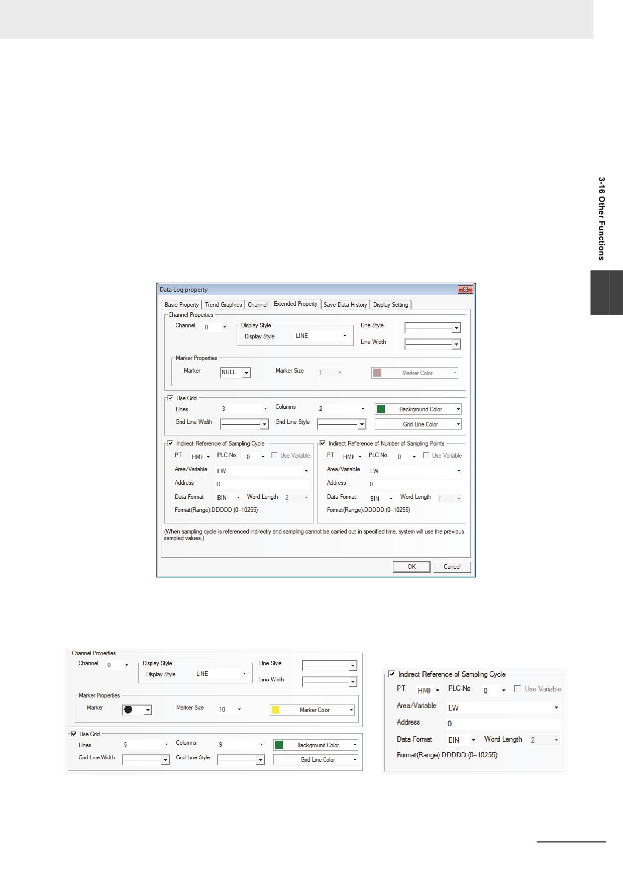
Data Log/XY Graph/Oscillograph components have extended Properties, as shown below:
(a) Border, Grid and Background Color etc.
(b) Display Type of sampling point.
(c) Sampling cycle can use the Indirect Reference.
(d) The style of XY Graph are scatter plot and shaded plot.
(e) Sampling points can use the Indirect Reference.
(f) The Data Log can be saved to the PT and external memory simultaneously.
3
When the sampling cycle and the sampling points are specified indirectly, if the value of the
reference address cannot be obtained, the value obtained previously can be used.
The extended properties of the data log are as follows:
NB-series Programmable Terminals NB-Designer Operation Manual(V106)
3-379
3 Functions of NB-Designer
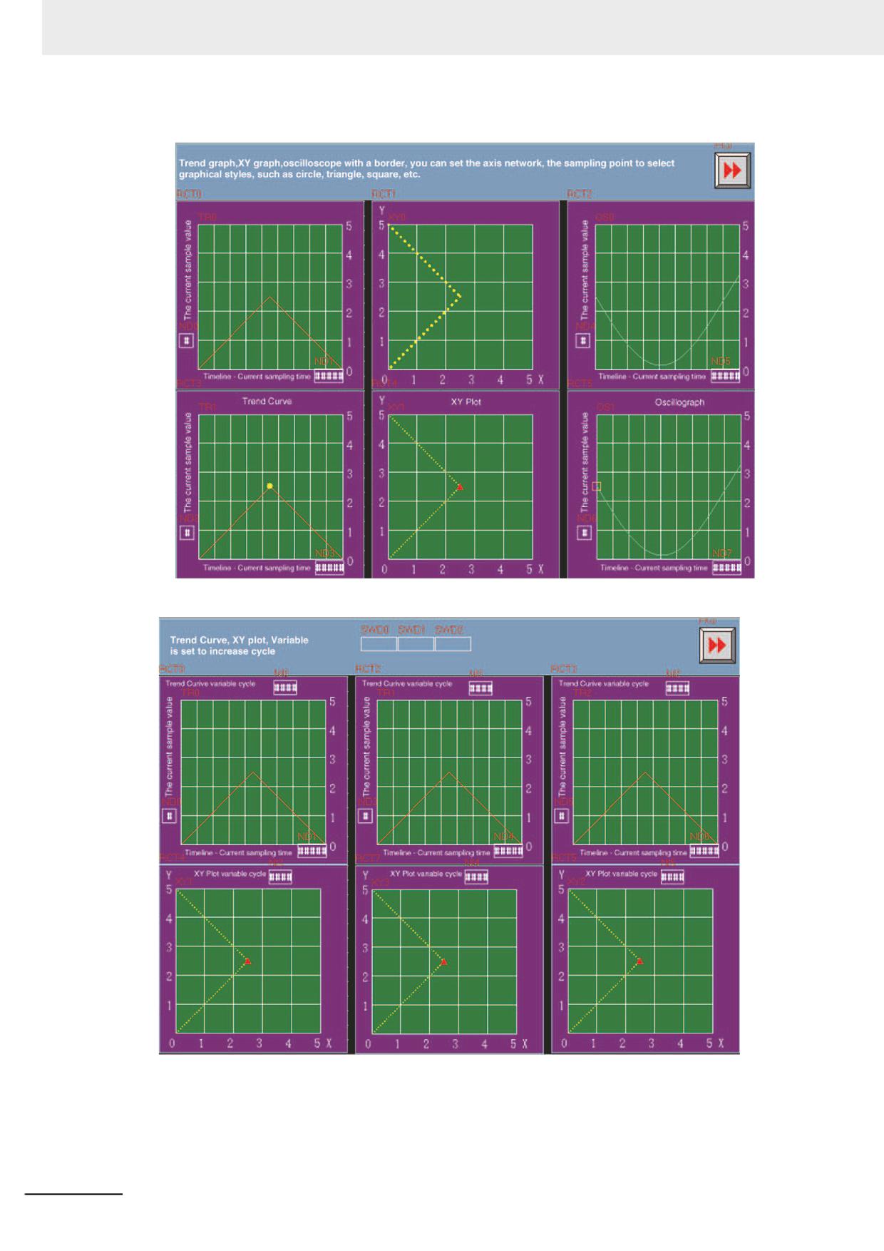
The effect of the screen is as shown below:
3-380
NB-series Programmable Terminals NB-Designer Operation Manual(V106)
3 Functions of NB-Designer
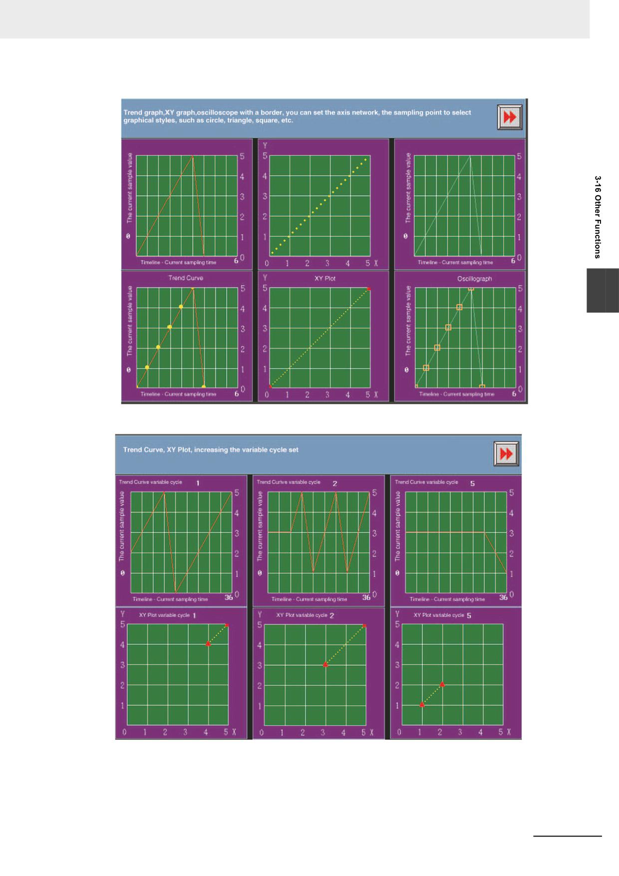
The effect of test is as shown below:
3
NB-series Programmable Terminals NB-Designer Operation Manual(V106)
3-381
3 Functions of NB-Designer
13 Use Input Order
The Number Input component, Text Input component and Note Book component have this
function.
Using the [Use Input Order] allows continuous input to Number Input component, Text Input
component, and Note Book component. Even if the “Enter” button is pressed, the keyboard will
not be closed automatically and will be kept to be opened and the cursor using [Use Input
Order] keeps moving among the components until the screen is closed by pressing “X” in the
top of the keyboard.
[Group] is used to classify the multi-group of components needing consecutive inputs. The
components with the same group number belong to the same group, and the cursor will be
cyclic in the same group of components. When the “Enter” is pressed, the keyboard will not be
closed automatically, but will always be displayed in the screen until the close button “X” in the
keyboard is clicked.
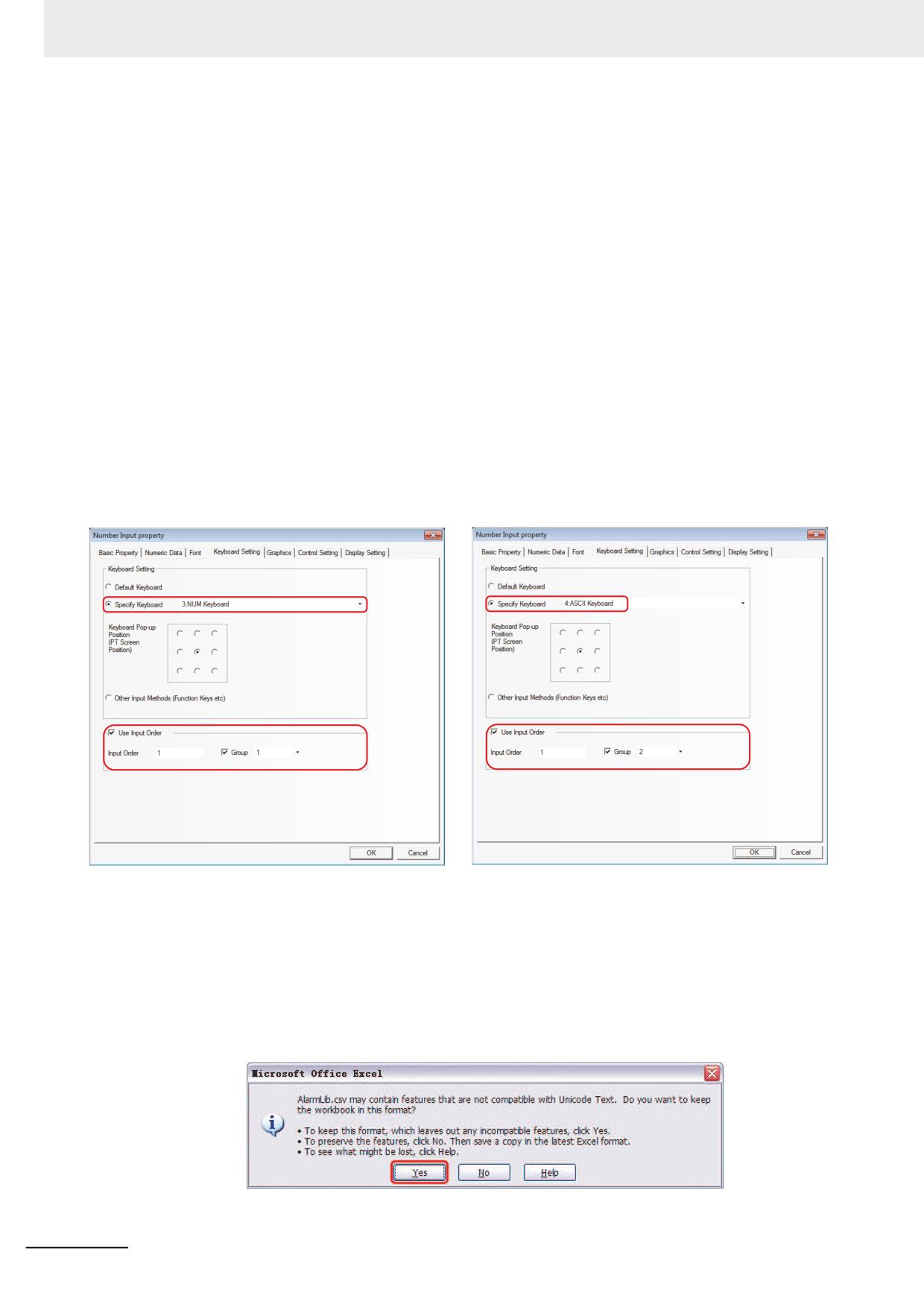
Setting of [Use Input Order]
Go to the [Keyboard Setting] Property tabs for the Number Input component, Text Input
component and Note Book component respectively, and check the [Use Input Order].
14 [Import/Export] of Background Component
The backg4round component including [Variable Table], [Text Library], [Alarm Setting], [Event
Setting] and [PLC Control] has the function of importing or exporting the file in .csv format. This
function is convenient to edit the related contents through the csv directly.
Note:
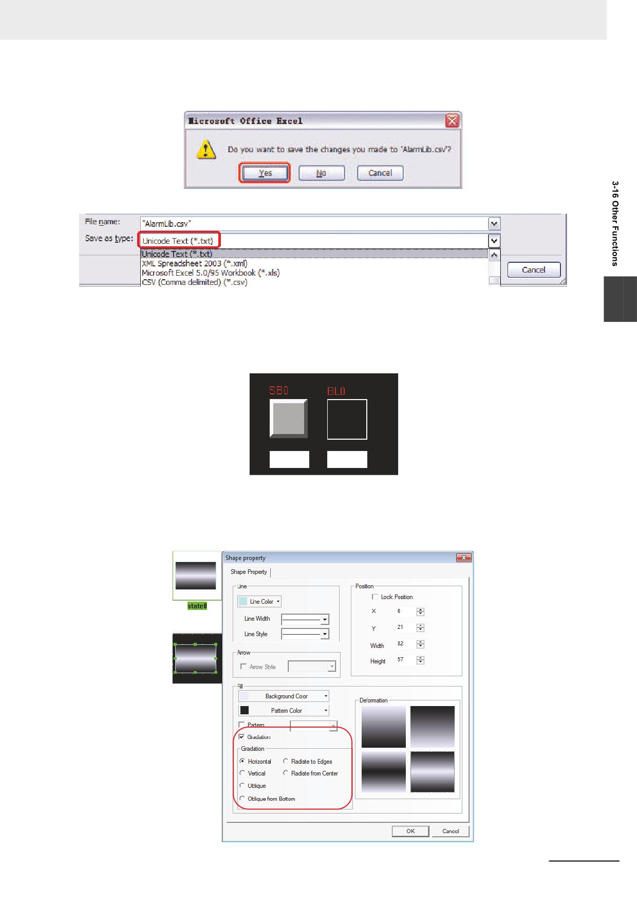
Please pay attention to the following points when saving the file in CSV format after it is edited.
(a) When the csv file is saved in Excel, click [Save] and select [Yes] as shown below:
3-382
NB-series Programmable Terminals NB-Designer Operation Manual(V106)
3 Functions of NB-Designer
(b) After selecting [File] - [Exit] in the menu, a dialog box as follows will be displayed and
select [Yes].
(c) [Unicode Text(*.txt)]must be selected from [Save as type].
3
(d) Change the extension of the saved file to csv.
15 Not Display Frame of Component
The frame of the component is not displayed when the component uses the graphics, but
displayed when the component doesn’t use the graphics, as shown below:
no display
display
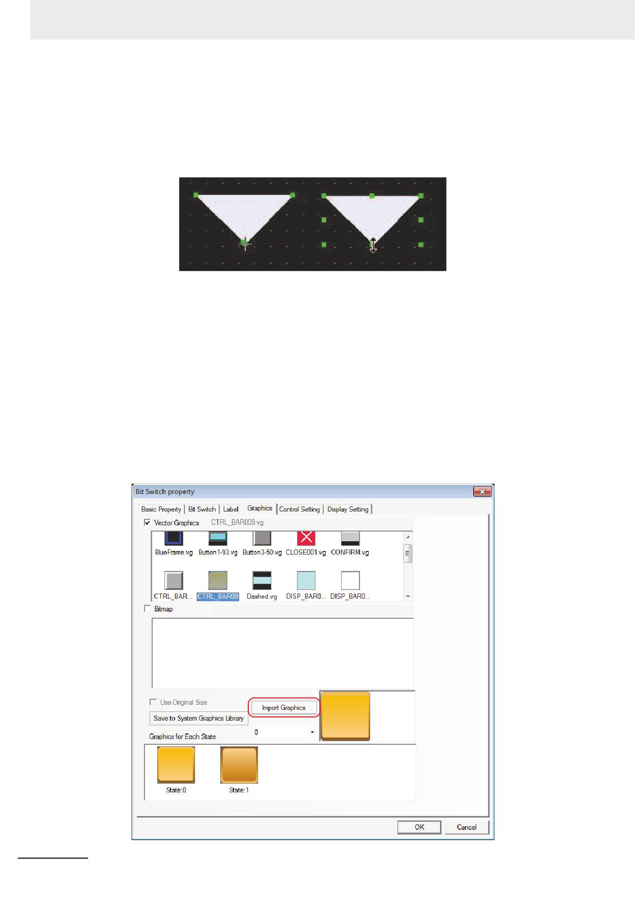
16 Gradation of Static Graphics
Gradation adds the effects to fill the graphics. And this function is useful for drawing the Vector
Graphics such as the piping with the gradation effect, as shown below:
NB-series Programmable Terminals NB-Designer Operation Manual(V106)
3-383
3 Functions of NB-Designer
17 Polygon Overall Zoom
The “Overall zoom in/out” added to the polygon allows the resizing without changing the shape.
After the component is clicked to turn into selecting state, one more click allows the editing the
top of the polygon. In the case, the cursor is turned to be appeared as “+” as follows. When the
cursor is appeared as “<->”, “Overall zoom out/in” can be performed.
18 Graphics Library
The display area is divided into two parts. All the graphics in the graphics library will be
displayed in the upper part while each state of the selected graphics will be displayed in the
lower part.
Bitmap and Vector Graphics are supported. Bitmap in .bg format is made of images in .bmp,
.gif, .jpg or .png formats or pictures. Using too many bitmaps will affect the operation speed of
PT. Therefore it is recommended to use the Vector Graphics to replace the bitmaps as much as
possible. The Vector Graphics in .vg format is drawn by the NB-Designer using the point, line
and circle, etc.
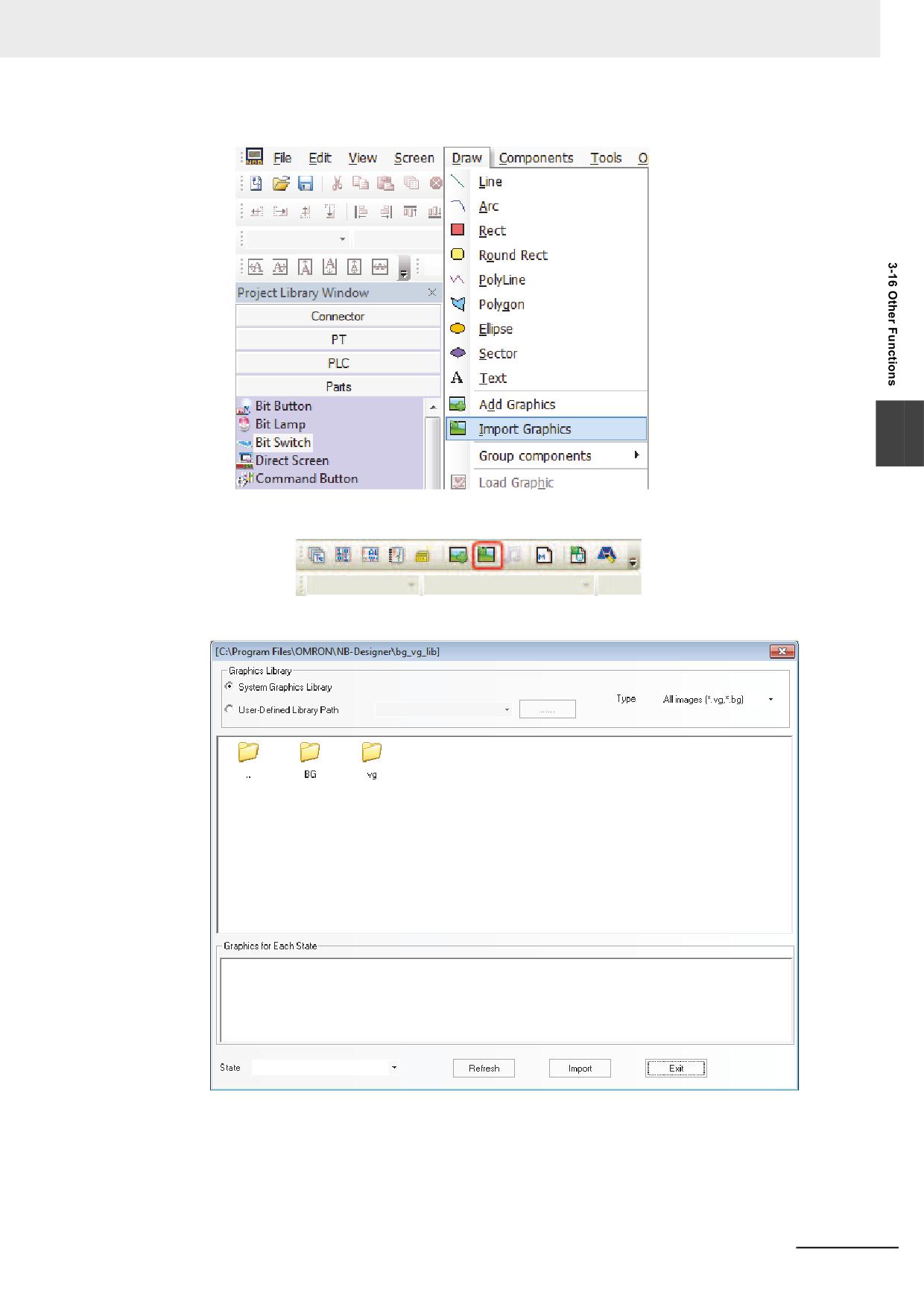
There are 3 methods to enter the Graphics Library window.
(1) Click [Import Graphics] in the [Graphics] tab in the component Property dialog box to enter
the grapchics library window (As shown below, take the Bit Switch component as example,
and the other components are similar.)
3-384
NB-series Programmable Terminals NB-Designer Operation Manual(V106)
3 Functions of NB-Designer
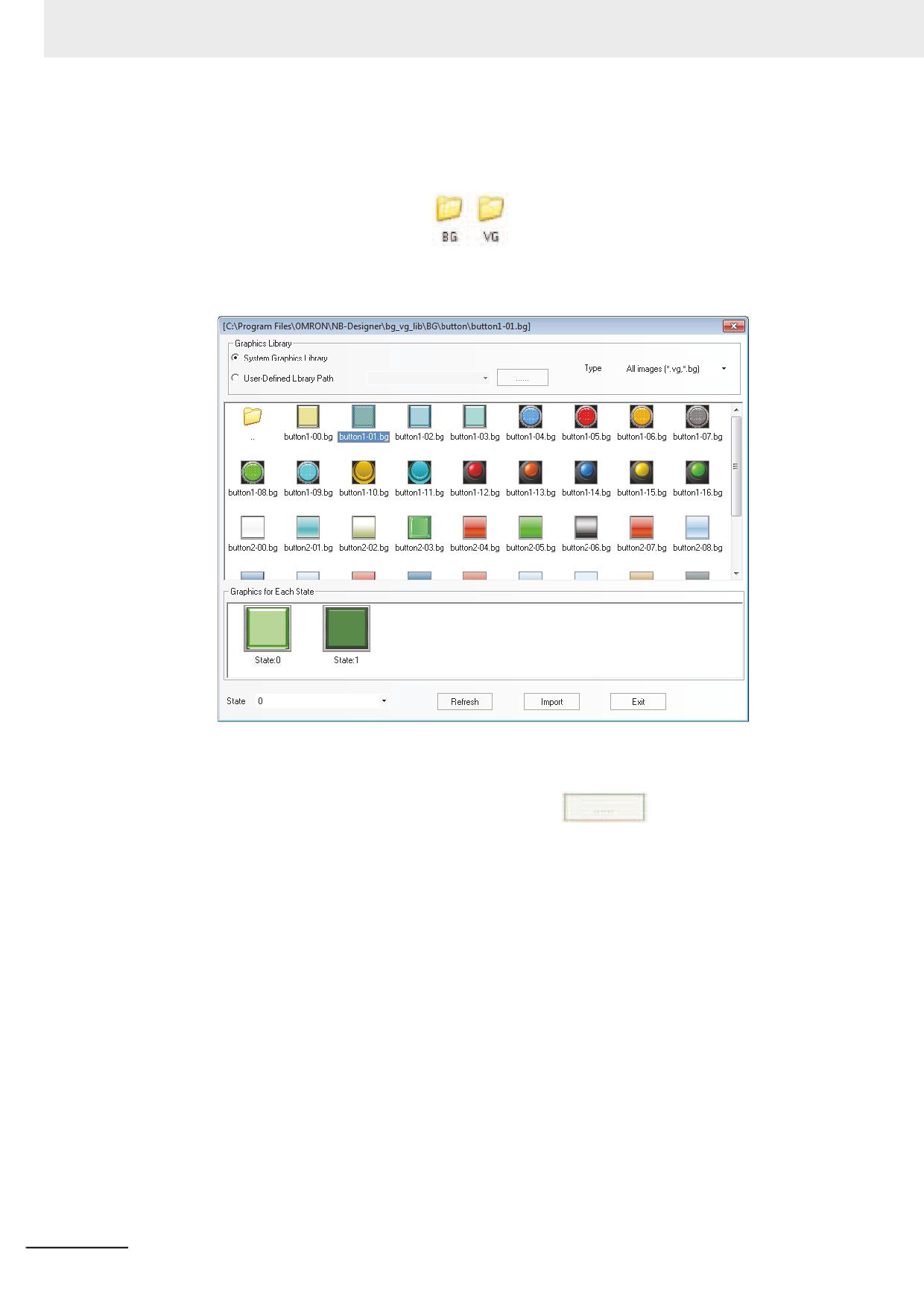
(2) Select [Import Graphics] in [Draw] menu to enter the Graphics Library window.
3
(3) Click [Import Graphics] icon in the toolbar to enter the Graphics Library window.
The Graphics Library window is shown as below:
NB-series Programmable Terminals NB-Designer Operation Manual(V106)
3-385
3 Functions of NB-Designer
There are 2 methods for selecting the Graphics Library:
(1) System Graphics Library: It is the graphics library provided by the software, it is under the
[bg_vg_lib] folder in the installation folder of the software.
Double-click [BG] or [vg] folder
, and then the bitmap images or vector graphics
installed by default will be displayed. The display area is divided into two parts. And all the
graphics in the graphics library will be displayed in the upper part while each state of the
selected graphics will be displayed in the lower part, as shown below:
(2) User-Defined Library Path: The folder is specified by the user to store the graphics library.
With this option, graphics in the other projects can be imported. The graphics used in each
project is saved in [vg] file for the project. Clicking
can reveal the file path.
The method of importing graphics is as follows:
Select one graphics, then click the [Import] button to import the graphics in the Graphics
Library to the project. Each time only one graphics instead of many can be imported to the
project.
3-386
NB-series Programmable Terminals NB-Designer Operation Manual(V106)
3 Functions of NB-Designer
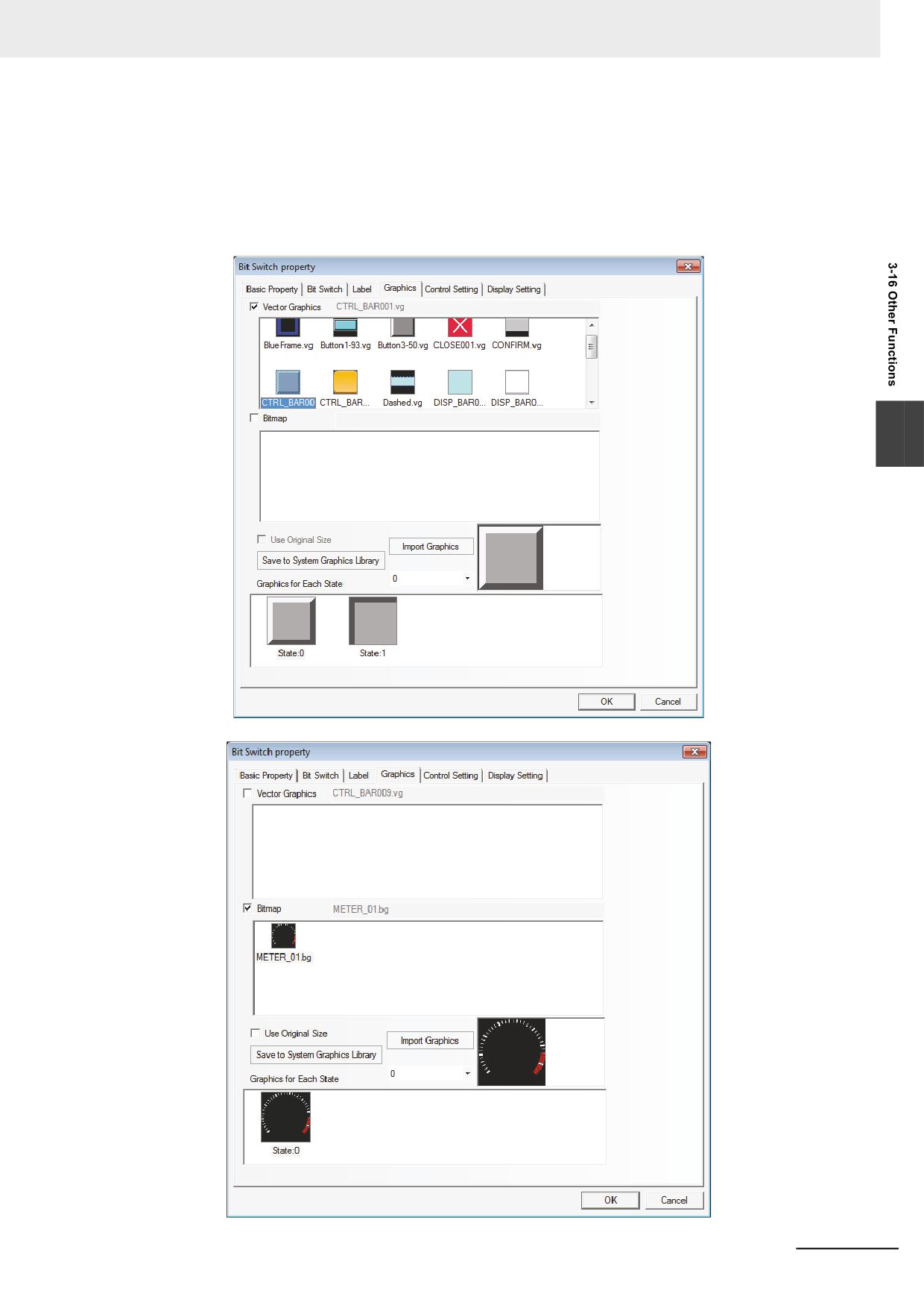
The method of using graphics:
Right-click the mouse on the selected component and select “Property” in the pop-up
menu, then go to [Graphics] tab to check Vector Graphics or Bitmap. The Vector Graphics
is checked by default. When [Vector Graphics] is checked, all the Vector Graphics
contained in the current project will be listed in the selection box of Vector Graphics, and all
the states of the selected graphics will be displayed in the [Graphics of Each State]
selection box, as shown below.
3
NB-series Programmable Terminals NB-Designer Operation Manual(V106)
3-387
3 Functions of NB-Designer
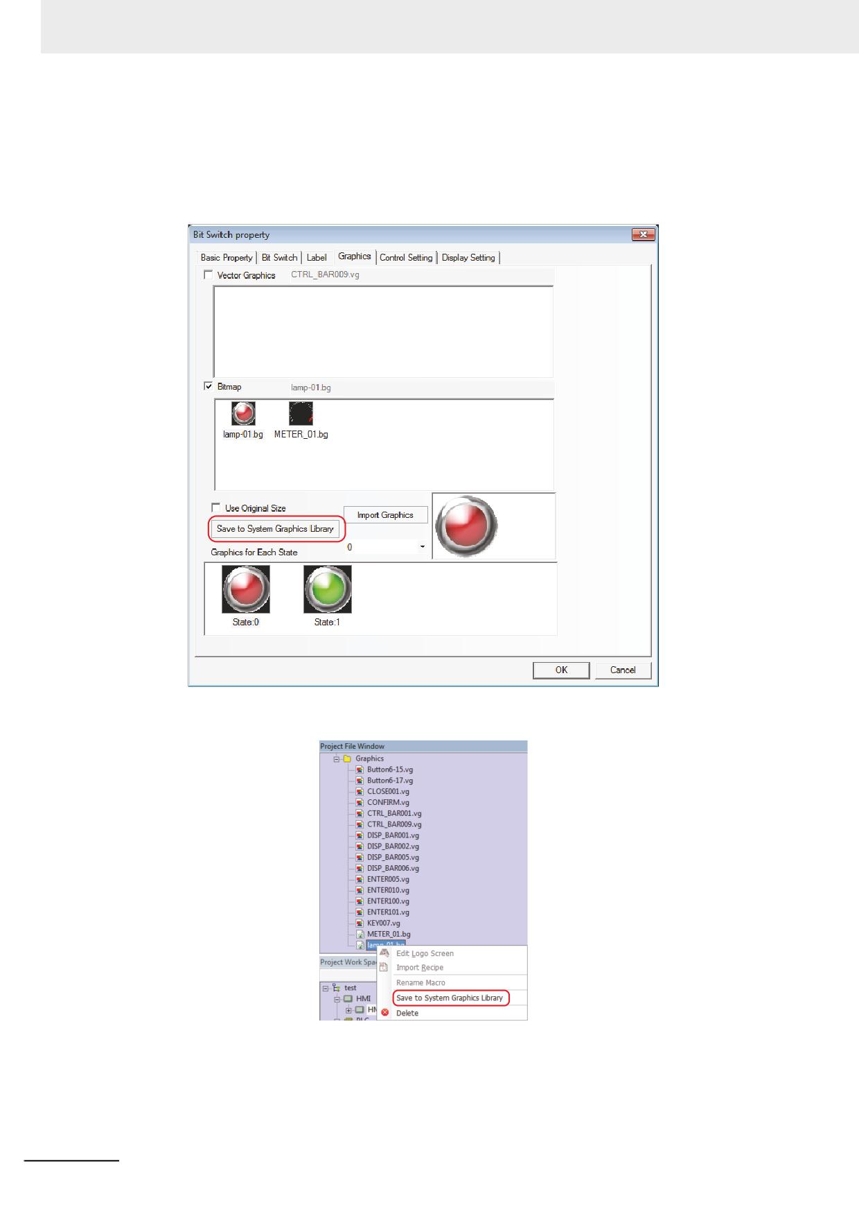
If new graphics needs to be added, click [Import Graphics].
Role of [Save to System Graphics Library] is to save the current graphics to the software for
the convenient call during the creation of other projects.
There are 2 methods for [Save to System Graphics Library]:
(1) Enter the [Graphics] tab and click [Save to System Graphics Library].
(2) Enter the [Graphics] in [Project File Window], select the current graphics, and right-click the
mouse to select [Save to System Graphics Library].
[Use Original Size] is intended for the user to conveniently make the graphics return to its
original size after it is zoomed out or in.
3-388
NB-series Programmable Terminals NB-Designer Operation Manual(V106)
3 Functions of NB-Designer
19 Support Graphics in GIF or PNG Format
The graphics in .gif or .png format can be imported directly during the creation of new graphics.
Using the graphics in .gif format can create the animation effect easily.
Using the graphics in .png format can create the transparent effect easily. For example, if the
Level Meter is added into the reaction vessel to show the current liquid level, then one reaction
vessel in .png format is needed.
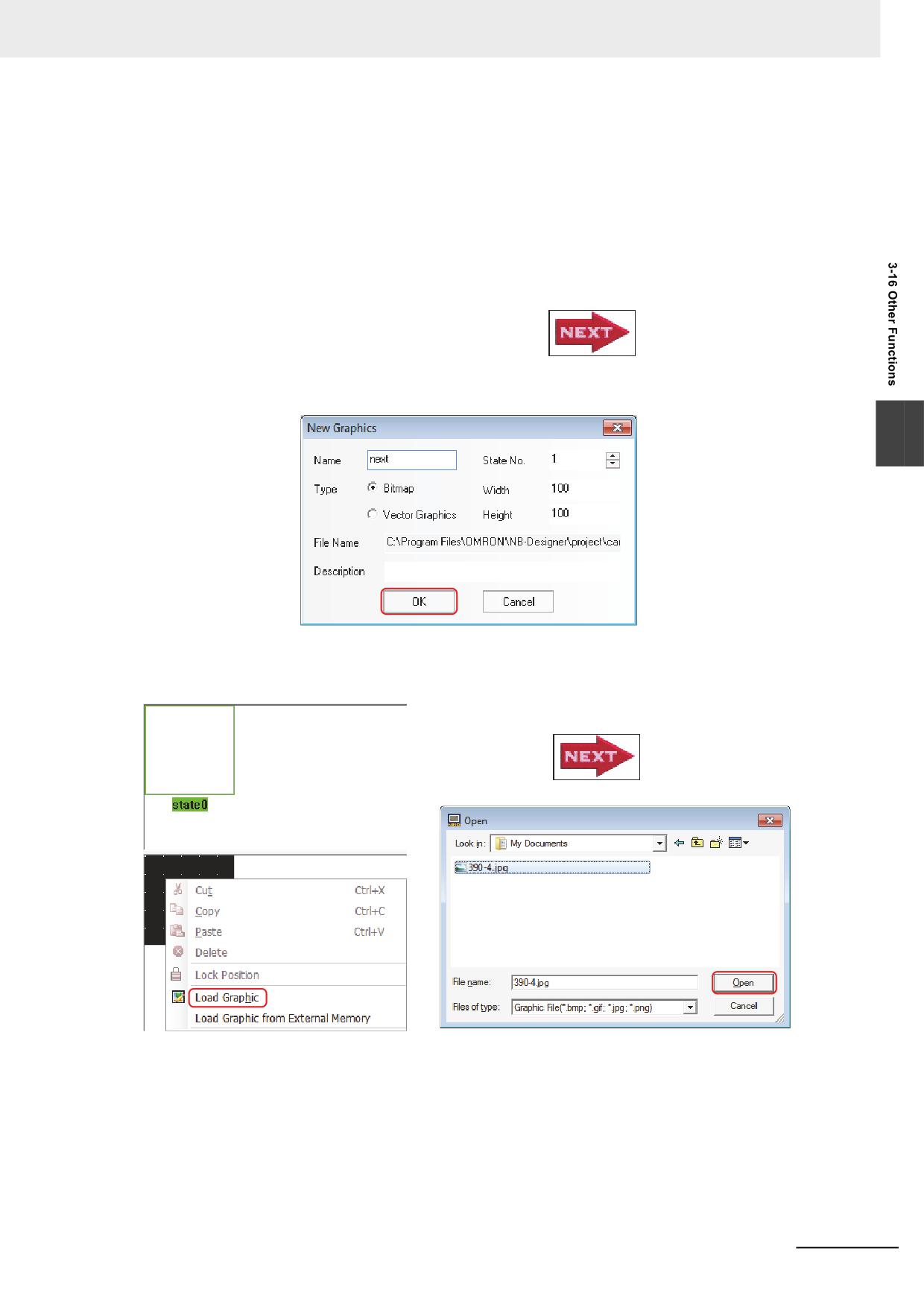
For example:
Use one graphics in .gif format with the effect like
(1) Click [Draw] menu to select [Add Graphics], and set the Name to “next”, Type to [Bitmap]
and other options to the defaults.
3
(2) Click the [OK] button to make the following editing box appear, and select [Load Graphic]
after right-clicking the mouse in the black editing box.
Select the graphics
NB-series Programmable Terminals NB-Designer Operation Manual(V106)
3-389
3 Functions of NB-Designer
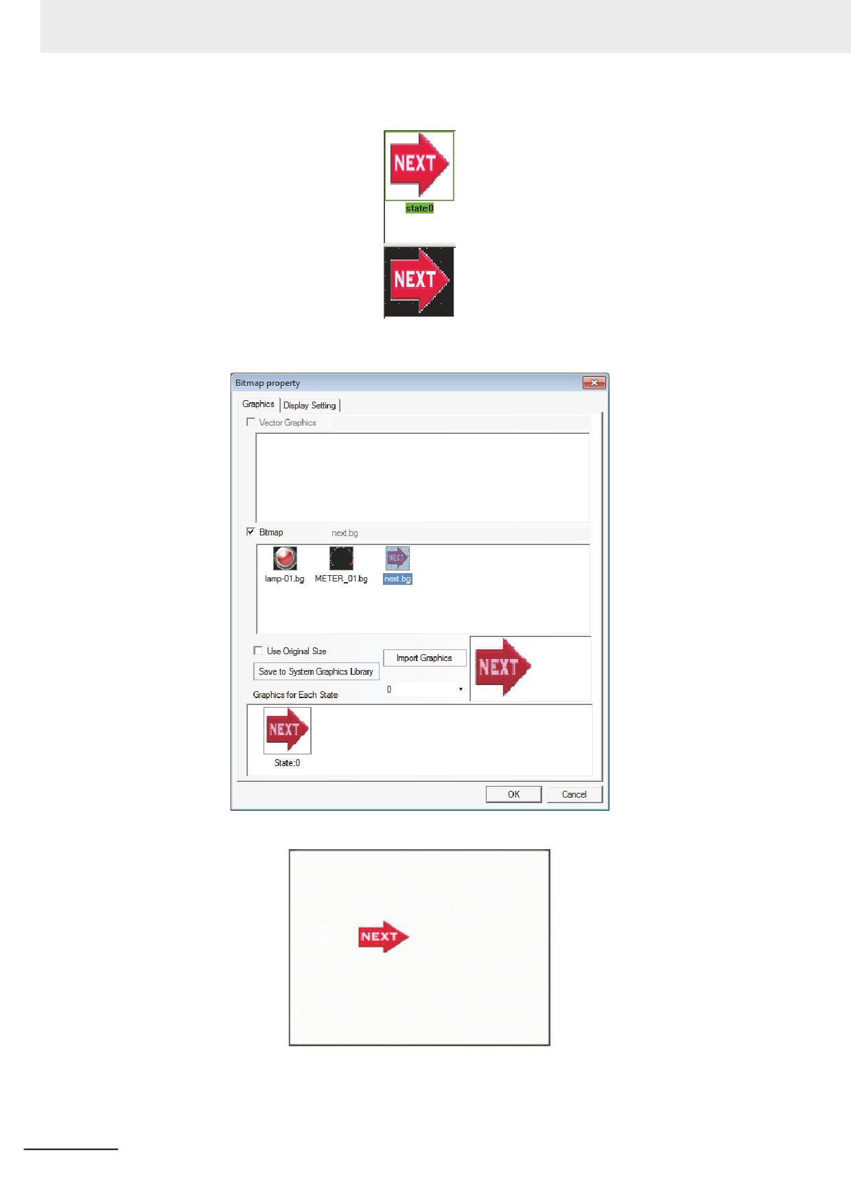
The successful import of graphics is as shown below:
(3) After saving the project, quit from the graphic edit window and enter the edit window.
(4) Place one Bitmap component, and check [Use Original Size].
(5) When the offline simulation is performed, and the effect is as shown below:
3-390
NB-series Programmable Terminals NB-Designer Operation Manual(V106)
3 Functions of NB-Designer
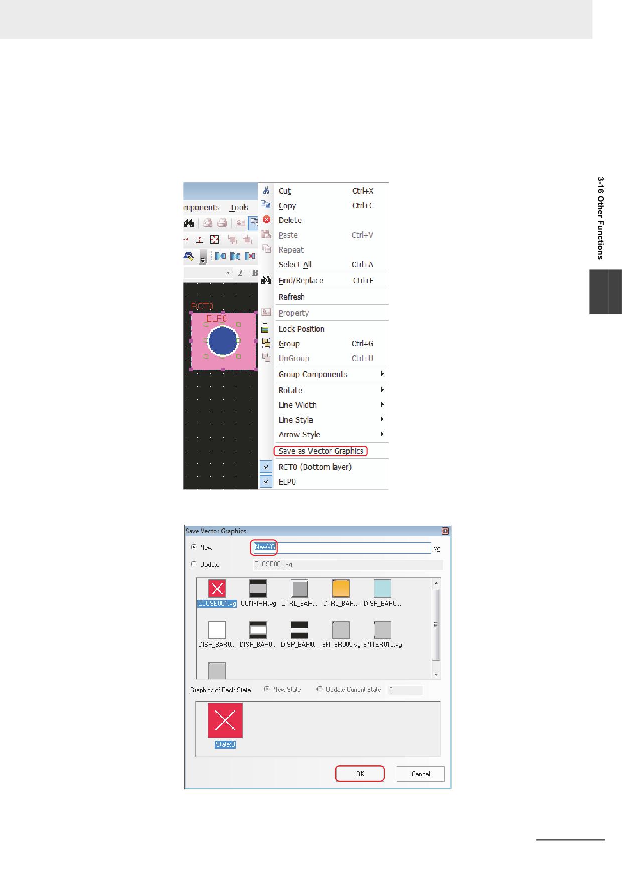
20 Save as Vector Graphics
Storing the graphics created from multiple graphic components allows the diversion to the
other screens.
The operation is as follows:
(1) Draw a rectangle and a circle, then select these two components and right-click the mouse
to select [Save as Vector Graphics].
3
(2) In the pop-up [Save Vector Graphics] dialog box, [New] is checked by default, and the
default name is NewVG. Click the [OK] button.
NB-series Programmable Terminals NB-Designer Operation Manual(V106)
3-391
3 Functions of NB-Designer
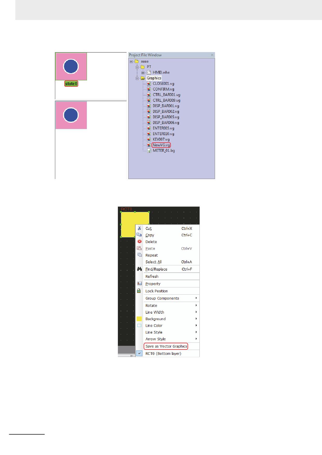
Then the creation of a new VG graphics with only one state (state0) is completed.
(3) For the addition of a Round rectangle into state1.
Draw a Round rectangle and select it, then right-click the mouse and select [Save as Vector
Graphics].
3-392
NB-series Programmable Terminals NB-Designer Operation Manual(V106)
3 Functions of NB-Designer
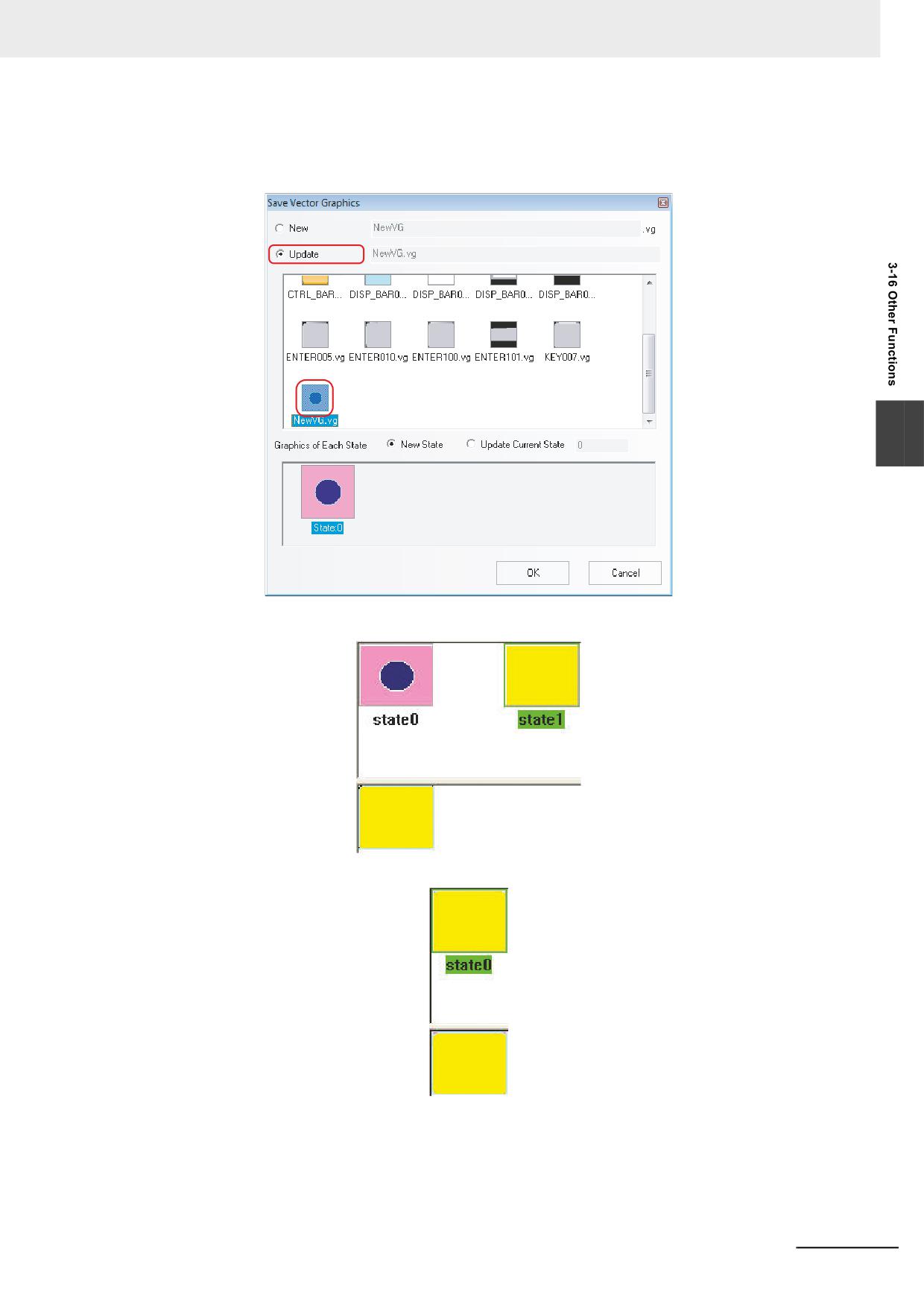
(4) Check in the [Update] radio button in the [Save Vector Graphics] dialog box and select a
NewVG.vg file. Then, select the state of the graphic to save the file.
3
[New State]: State1 will be added.
[Update Current State]: State0 will be replaced.
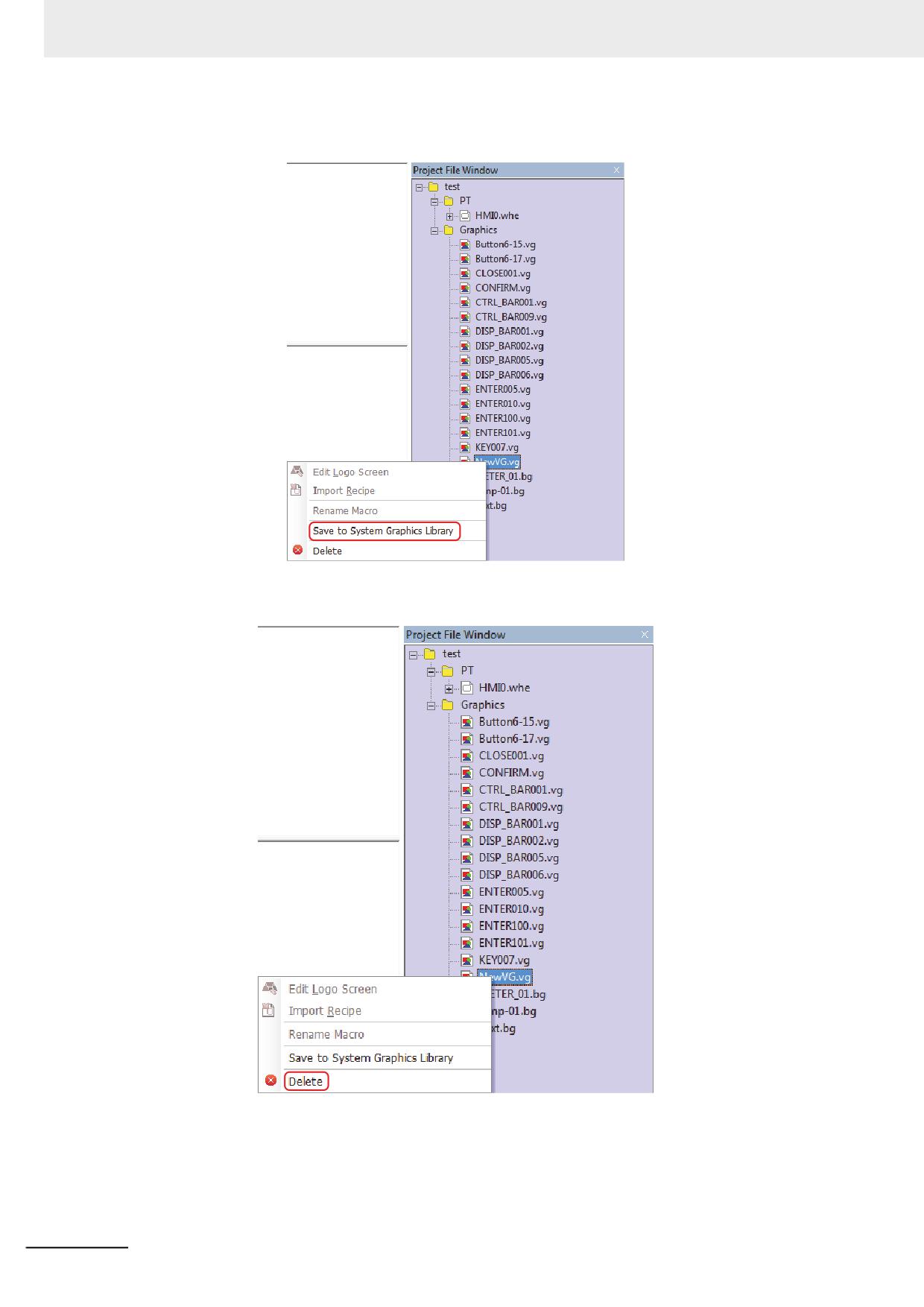
[Save to System Graphics Library]: The new created NewVG.vg will be saved to the system
library for the convenient call of this graphics by the other projects. For the method to call
graphics, refer to the 18 Graphics Library (Page 3-384).
NB-series Programmable Terminals NB-Designer Operation Manual(V106)
3-393
3 Functions of NB-Designer
Method of [Save to System Graphics Library]: Select the NewVG.vg in [Project File
Window], then right-click the mouse to select [Save to System Graphics Library].
[Delete] (Method of deleting the new created NewVG.vg): Select the NewVG.vg in [Project
File Window], then right-click the mouse to select [Delete].
3-394
NB-series Programmable Terminals NB-Designer Operation Manual(V106)
3 Functions of NB-Designer
21 Using Graphics From External Memory
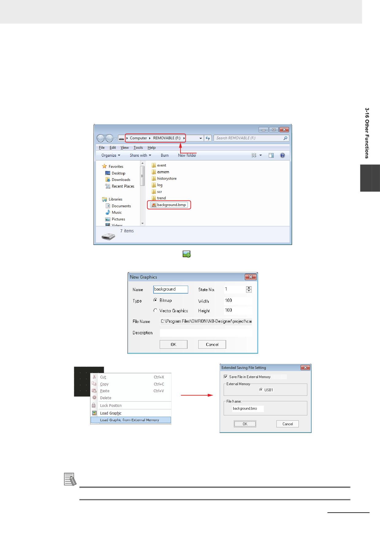
NB-Designer also supports the bitmap data directly calling the graphics from the external
memory in order to save the memory space of the PT.
For example:
Create a backg4round picture named “background.bmp” and save it in the root folder of external
memory (Here refers to USB1). Then the project will directly call the picture named
“backg4round.bmp” from external memory.
(1) Copy the picture named “backg4round.bmp” into the root folder of external memory.
Root Directory
3
(2) Create new graphics: Click the
icon in the toolbar or select “Add Graphics” option in the
[Draw] menu; and enter “backg4round” in the Name option, select “1” in State No. option and
check “Bitmap” in Type option after the [Add Graphics] dialog box pops up.
(3) Specify the setting for graphics which is called from external memory in status editing area.
Note 1
[File Name] must be same as that of the bitmap to be called from the external memory.
2
The formats of the graphics which can be called from external memory are BMP, JPG, and GIF only, not PNG.
3
The pictures must be saved in the root folder of the external memory.
(4) The creation of backg4round picture is completed, and then exit from this operation after save it.
Additional Information
The display will be updated without the restart by turning LB9108 ON.
NB-series Programmable Terminals NB-Designer Operation Manual(V106)
3-395
3 Functions of NB-Designer
22 Group Components
Several components or the graphics are combined together and saved into the Group
Components Library, thus making them called by other projects conveniently.
The format of Group Components Library is .pgl.
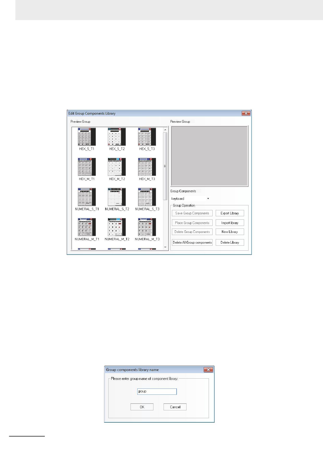
(1) Method of entering [Edit Group Component Library]
Click [Use Group Component] in [Group components] in [Draw] menu or right-click the mouse
in the blank area of the window the select [Use Group Component] in [Group Components],
then the [Edit Group Components Library] dialog box will pop up, as shown below:
[Export Library]
Clicking [Export Library] can make the [Group Components Library] saved to the folder
specified.
[Import Library]
The default path of group components is the usrlib folder under the installation path of NB-
Designer, and the user can also import the group components library from the self-defined
path. Click [Import Library], and select the required group components library in the path
corresponding to the saved group components library, then click [Open] to add this group
components library to the group components library of the current project.
[New Library]
Clicking the [New Library] button will make the following dialog box pop up, and the user
can input the name of this new created group components library in it. The default path to
save the group components library is the usrlib folder under the installation path of the
software.
3-396
NB-series Programmable Terminals NB-Designer Operation Manual(V106)
3 Functions of NB-Designer
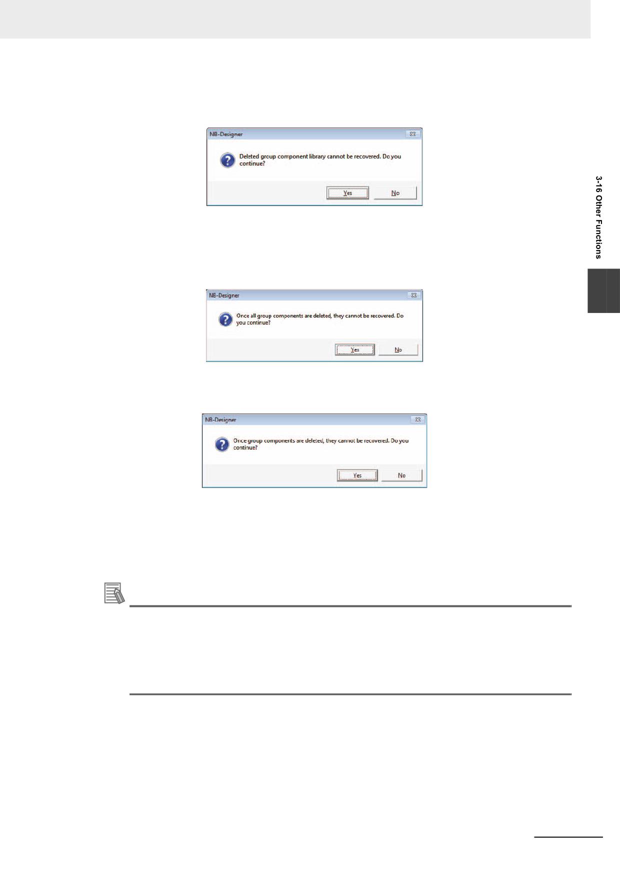
[Delete Library]
Clicking the [Delete Library] button will delete the group components library opened
currently.
Clicking “Yes” will delete the current group components library from this project, while
clicking “No” will ignore the operation done just now.
[Delete All Group Components]
Clicking the [Delete All Group Components] button will delete all the components in the
group components library opened currently.
3
[Delete Group Components]
Clicking the [Delete Group Components] button will delete the components in the group
components library opened currently.
Note “Delete Library”, “Delete Group Components” and “Delete All Group Components” will directly
delete the related files in the usrlib folder under the installation path of the NB-Designer.
[Place Group Components]
Clicking the [Place Group Components] button will place the selected components in the
group components library opened currently into the screen edited currently.
Additional Information
• Some group components contain macros. If a macro with the same file name already exists in
the project in which the group component is to be placed, the macro information will be output
as a MacroConflict.txt file to the folder of the project in which the group component is placed.
• Some group components contain the PLC address information. If the project in which a group
component to be placed does not have the same PLC, the information will be converted to
LB0/LW0.
NB-series Programmable Terminals NB-Designer Operation Manual(V106)
3-397
3 Functions of NB-Designer
For example:
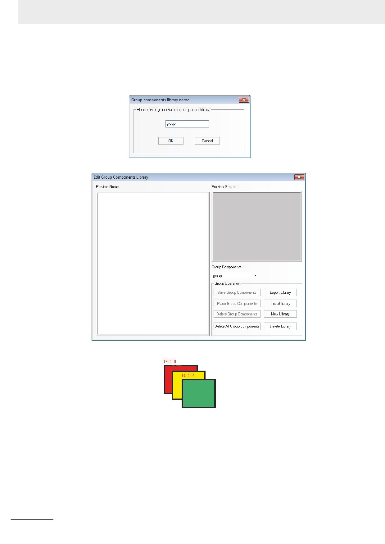
How to add group components to a new created group components library is described as follows:
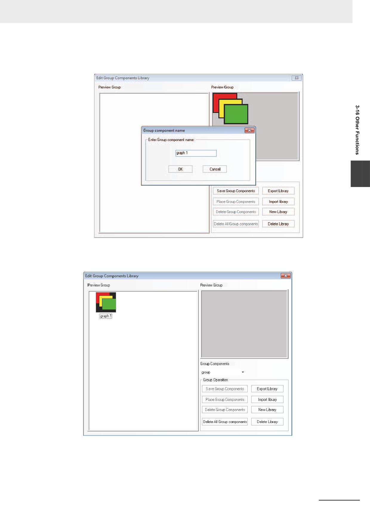
(1) Click [Use Group Components] in [Group components] in [Draw] menu, and click [New Library]
after the Edit Group Components Library pops up, and input “group” as the name of the group
components library in the Group component library name dialog box, as shown below:
Click the [OK] button to create an empty group components library as shown below:
(2) Place 3 rectangles in the screen, as shown below:
3-398
NB-series Programmable Terminals NB-Designer Operation Manual(V106)
3 Functions of NB-Designer
Select these 3 rectangles, and right-click the mouse to select [Group Components] - [Save
Group Components], and then click the [Save Group Components] button in the Edit Group
Components Library dialog box to make the following dialog box pop up.
3
(3) Input “graph 1” in the Part Group Name dialog box and then click the [Ok] button, then
these 3 rectangles with the name of [graph 1] will be added into the new created group
components library with the name of [group], as shown below:
(4) If there are other group components to be added into the group components library with the
name of [group], the operation method is the same as that mentioned above. And you just
need to select [group] in the Group Components location in Edit Group Components Library
dialog box as the path to save it.
NB-series Programmable Terminals NB-Designer Operation Manual(V106)
3-399
3 Functions of NB-Designer
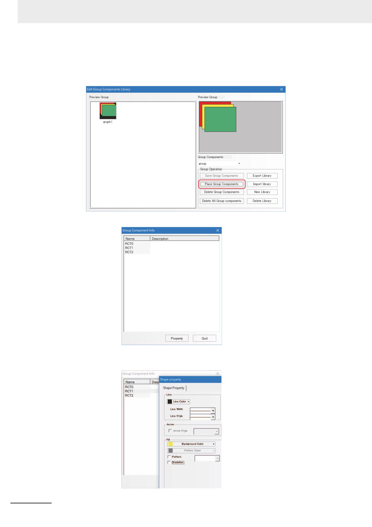
23 Edit Group Components
Group components can be edited remaining grouped.
(1) Select [Place Group Components] in [Edit Group Components Library].
(2) Double-click a group component to display the [Group Component Info] dialog box.
(3) Select a component and open the property window to change the component's settings
remaining grouped.
3-400
NB-series Programmable Terminals NB-Designer Operation Manual(V106)
3 Functions of NB-Designer
24 Usage of Keyboard
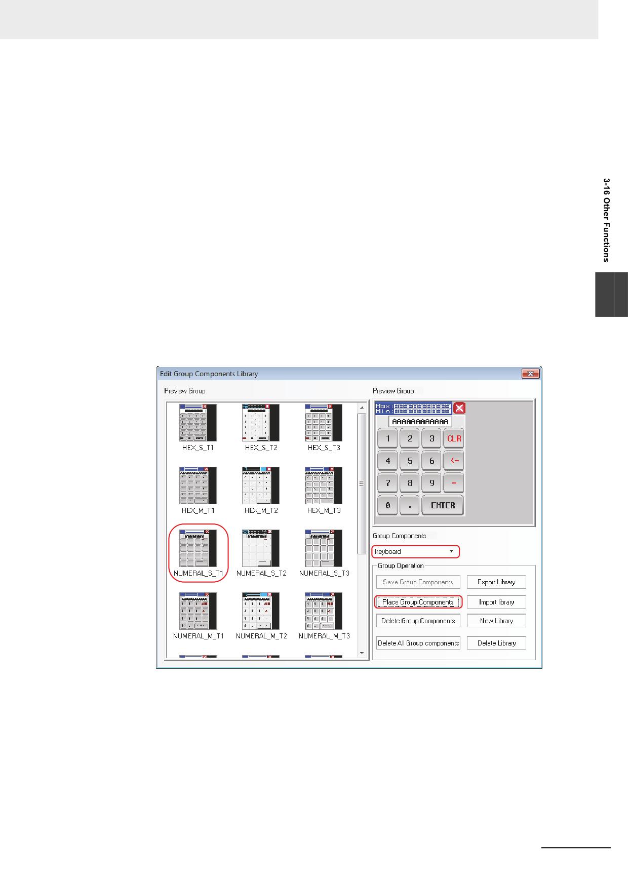
NB-Designer provides 21 default keyboards in [Group Components Library], and the
keyboards are as follows:
3 small keyboards with different styles: HEX Keyboard (HEX_S_T1 to HEX_S_T3), NUM
Keyboard (decimal, NUMERAL_S_T1 to NUMERAL_S_T3) and ASCII Keyboard (ASCII_S_T1
to ASCII_S_T3), which are applicable to the small PT with the resolution not more than
320×240.
3 middle keyboards with different styles: HEX Keyboard (HEX_M_T1 to HEX_M_T3), NUM
Keyboard (decimal, NUMERAL_M_T1 to NUMERAL_M_T3) and ASCII Keyboard
(ASCII_M_T1 to ASCII_M_T3), which are applicable to the large PT with the resolution not less
than 640×480.
3 small grey decimal NUM Keyboards with different styles: NUMERAL_S_L1 to
NUMERAL_S_L3.
How to call the keyboard in the group components library is described as follows:
3
(1) Click [Use Group Components] in [Group components] in [Draw] menu, or right-click the
mouse in the blank area in the window to select [Group Components] - [Use Group
Components], then select [keyboard] from [Group Components] in [Edit Group
Components Library], finally select [NUMERAL_S_T1] from [Preview Group] and click the
[Place Group Components] buttons, as shown below:
NB-series Programmable Terminals NB-Designer Operation Manual(V106)
3-401
3 Functions of NB-Designer
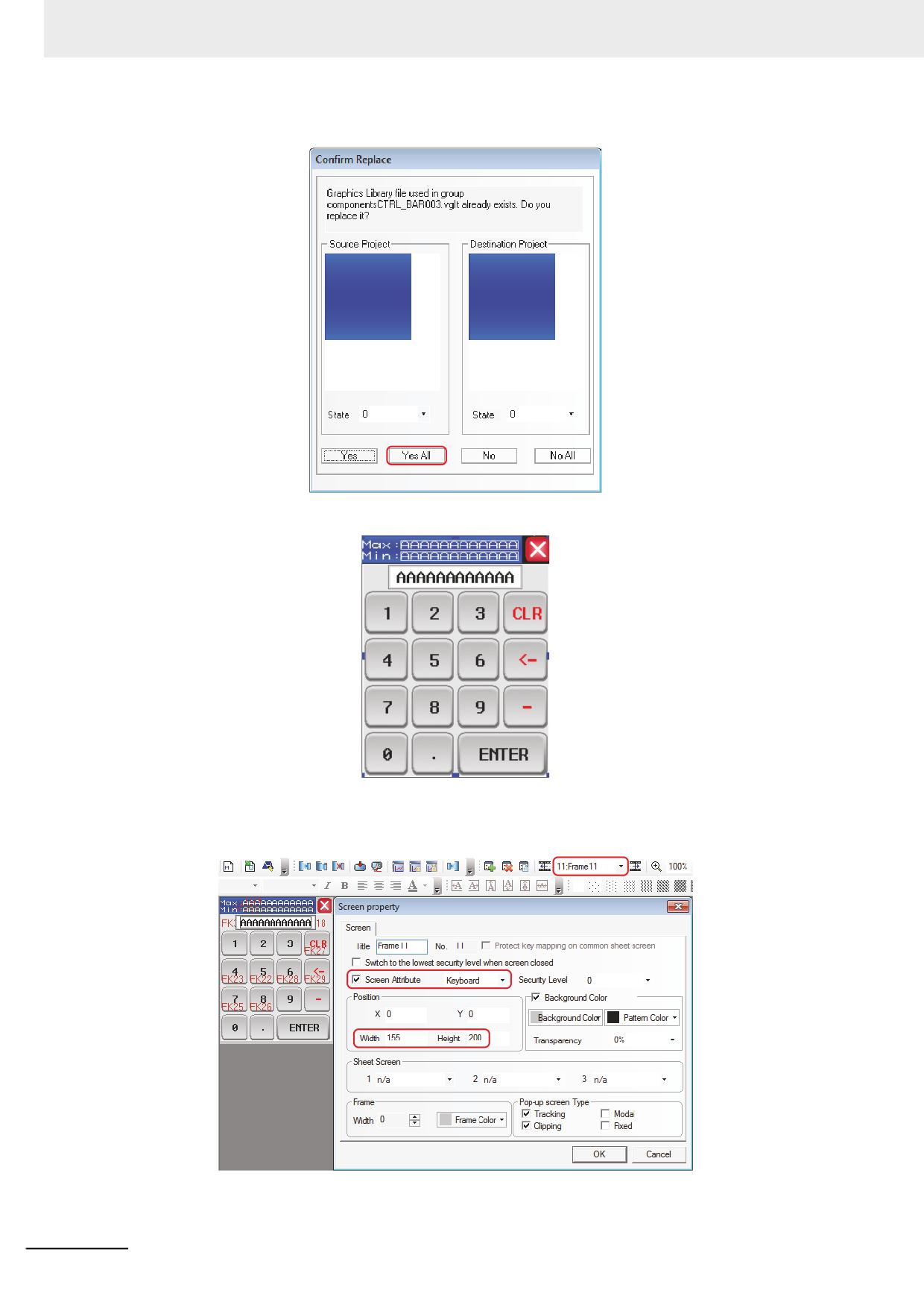
(2) Click the [Yes All] button in the Confirm Replace Dialog.
(3) Close [Edit Group Components Library] and one keyboard will appear in the screen.
(4) Place this keyboard in Frame 11, double-click the mouse and change Width and Height,
select [Keyboard] after Special Attribute being checked and make the other settings in
Screen Property dialog box, as shown below:
Note [Keyboard] in [Screen Attribute] must be selected in [Screen Property] dialog box.
3-402
NB-series Programmable Terminals NB-Designer Operation Manual(V106)
3 Functions of NB-Designer
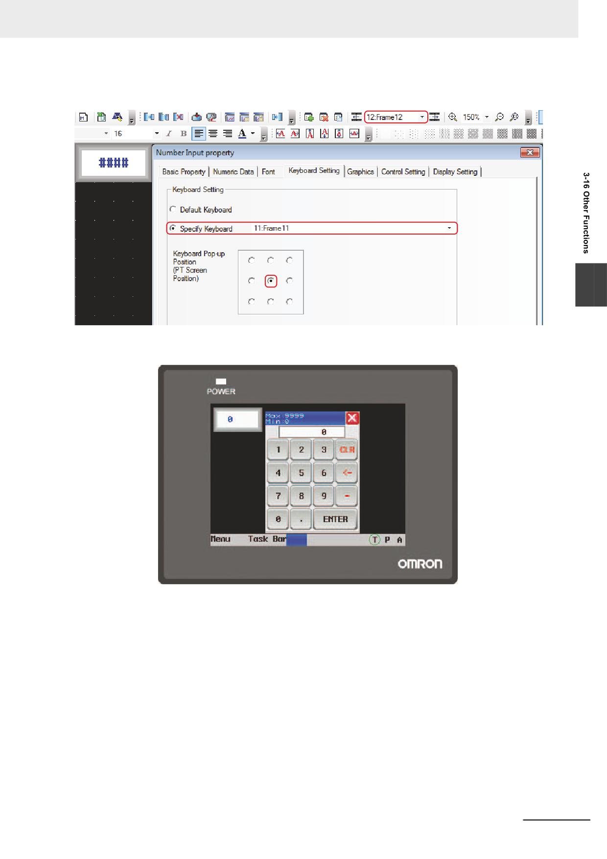
(5) Place one Number Input component in Frame 12, and select [Specify Keyboard] in
[Keyboard Setting] tab, as shown below:
3
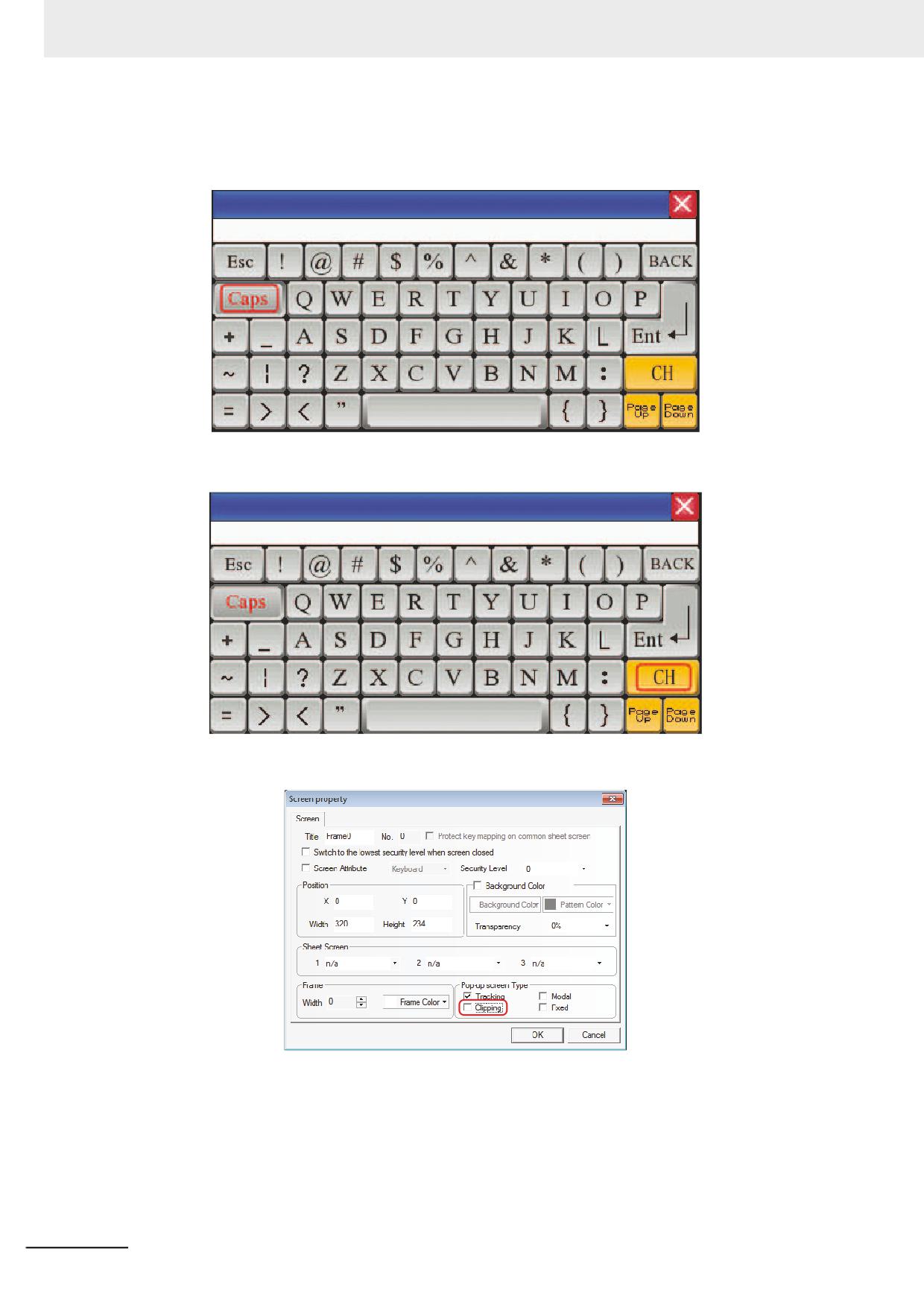
(6) Perform the offline test and click the Number Input component to make the keyboard pop
up, as shown below:
NB-series Programmable Terminals NB-Designer Operation Manual(V106)
3-403
3 Functions of NB-Designer
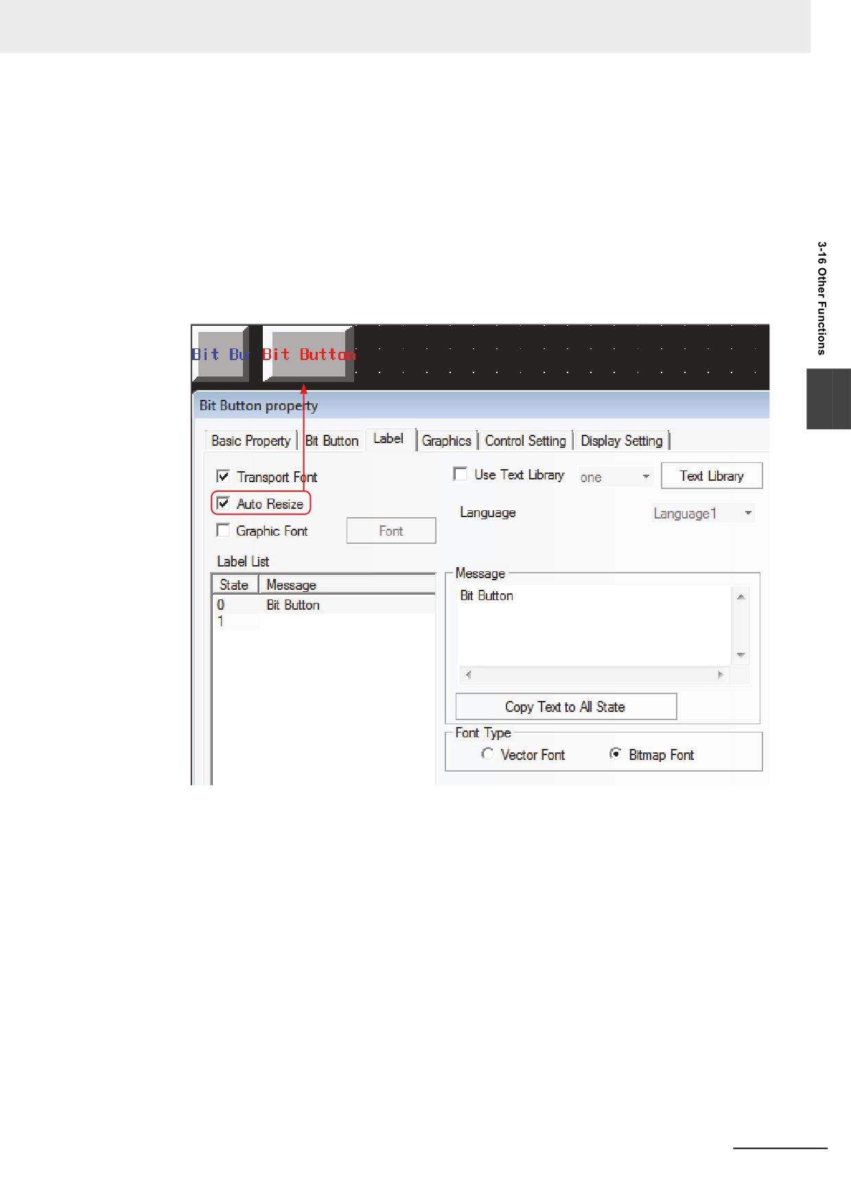
The usage of ASCII keyboard is described as follows:
(1) Support Case: Pressing the Caps key in the keyboard can realize the case switching, as
shown below:
(2) Support Chinese and English Input Methods: Pressing CH key in the keyboard can realize
the switching between Chinese and English, as shown below:
Note If the keyboard is called by the Pop-up Screen, [Clipping] in Pop-up Screen Type must not be checked, as
shown below:
3-404
NB-series Programmable Terminals NB-Designer Operation Manual(V106)
3 Functions of NB-Designer
25 Auto Resize
Checking the [Auto Resize] check box in the [Label] tab, when the label is too long or the
multiple languages with different sizes, allows adjustment the size of the component. [Auto
Resize] is checked by default.
After [Auto Resize] is checked, when the length of label exceeds the width of the component,
the component will be extended automatically, thus making all the contents of the label
displayed completely.
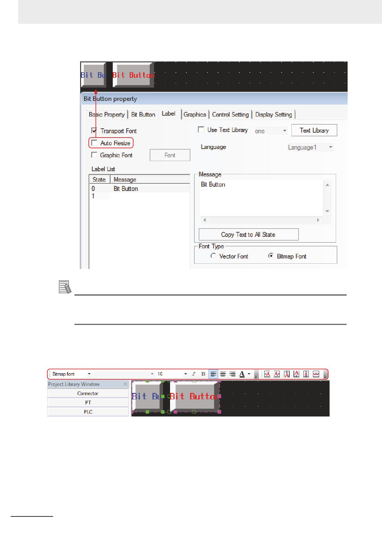
If [Auto Resize] is not checked, when the length of label exceeds the width of the component,
the component will not be extended automatically, thus making part of contents of the label
displayed. The effect is shown as below.
3
NB-series Programmable Terminals NB-Designer Operation Manual(V106)
3-405
3 Functions of NB-Designer
Additional Information
You can disable this setting: select [Disable Auto Resize] in the [PT Extended Property]. (Refer
to 3-10-3 PT Extended Properties (Page 3-295)) for the behavior with the option [Disable Auto
Resize] selected.
26 Overall Modify Font
Select all the components to be modified, and click each icon in [Font Toolbar] and [Text
Position Toolbar] to overall modify the properties.
3-406
NB-series Programmable Terminals NB-Designer Operation Manual(V106)
3 Functions of NB-Designer
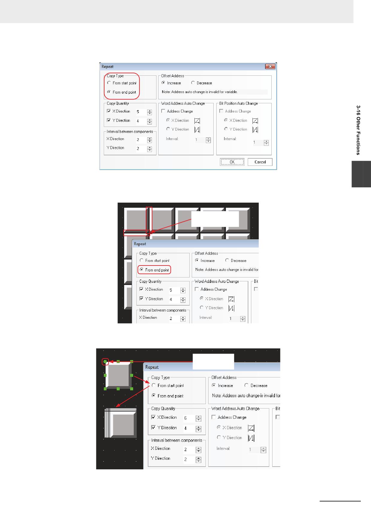
27 Repeat
3
Difference between [From start point] and [From end point]:
[From end point] specifies the top in the lower right border of the component to the starting
point to copy.
Make the right border
as the start point
[From start point] specifies the top in the upper left corner of the component to the starting point
to copy.
Make this point as
the start point
28 Conveniently Use System memory
NB-series Programmable Terminals NB-Designer Operation Manual(V106)
3-407
3 Functions of NB-Designer
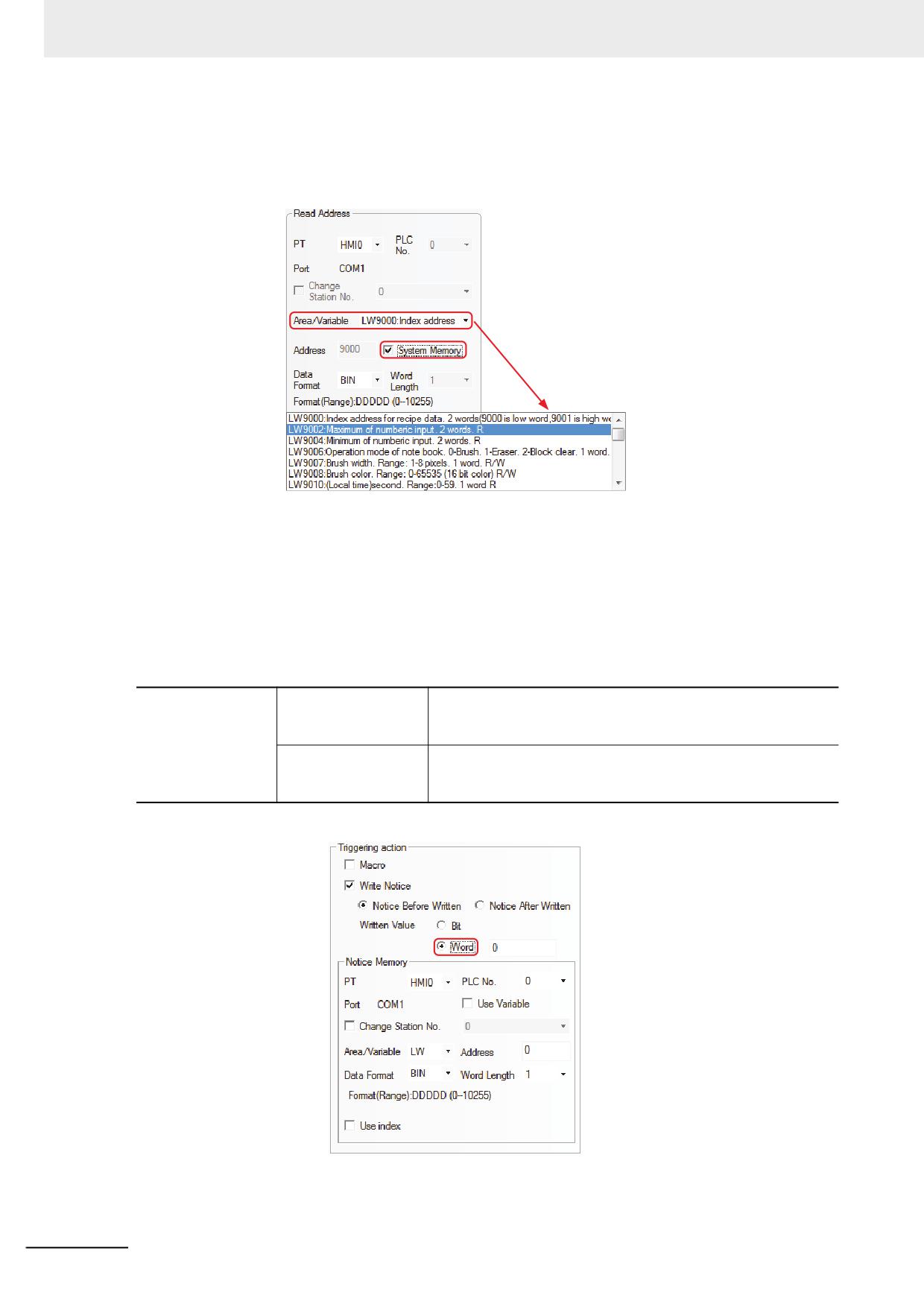
If you want to use or check the System memory, check the [System Memory] check box in
Basic Property dialog box. The descriptions of all the bit system memories or word system
memories are listed in [Area/Variable], as shown below:
29 Simultaneously Open Multiple Projects/Cross-project Copy/Paste
Open 2 NB-Designers. Open 2 projects with different names, and then copy or paste the
current screen by using shortcuts “CTRL+C” and “CTRL+V” or selecting [Edit] - [Copy/Paste].
30 Use Notifications Function to Notify Word memory
Notifications to word memories are added in [Control Setting] tab for the Bit Button component,
Bit Switch component, and Number Input component etc.
Write Notice (Word)
Notice Before Written
Makes the write value written into the specified word memory
before the signal of touch component is input into the controller
successfully.
Notice After Written
Makes the write value written into the specified word memory
after the signal of touch component is input into the controller
successfully.
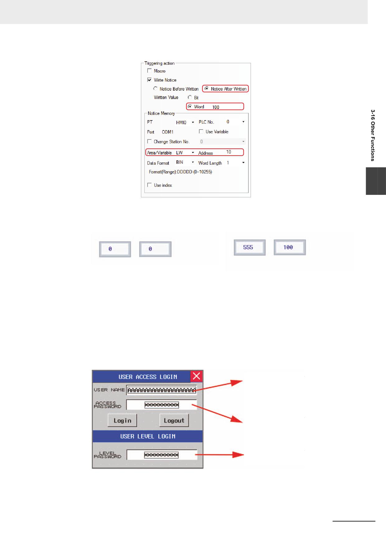
For example, Number Input component LW0 notifies LW10 to write 100 after notification.
Set [Triggering action] in [Control Setting] as shown below:
3-408
NB-series Programmable Terminals NB-Designer Operation Manual(V106)
3 Functions of NB-Designer
3
Perform the offline test and the effect is as shown below:
Before data written into LW0:
After data written into LW0:
LW0
LW10
LW0
LW10
Before write value to LW0, LW10=0(defaut value)
After written value to LW0,
LW10 has been noticed to be written value
31 Specify “Auto show login screen” to the Component controlled by operations
The [Touch Enabling Setting] in the [Control Setting] tab of the [Component Property] includes
[Auto show login screen] function. NB-Designer makes the Frame9 as the password input
screen (Login Screen), which is convenient for the user to call it when the security level or user
permission is used.
Login Screen includes USER ACCESS LOGIN and USER LEVEL LOGIN screens. You can
input the correct USER NAME and ACCESS PASSWORD and then click “Login” or “Logout” in
USER ACCESS LOGIN screen to complete the login or logout when the user access function
is used; and you can input the correct LEVEL PASSWORD in the USER LEVEL LOGIN screen
to complete the level login when the user level login function is used.
Input box for user name
of user permission
Input box for password
of user permission
Input box for password
of user level
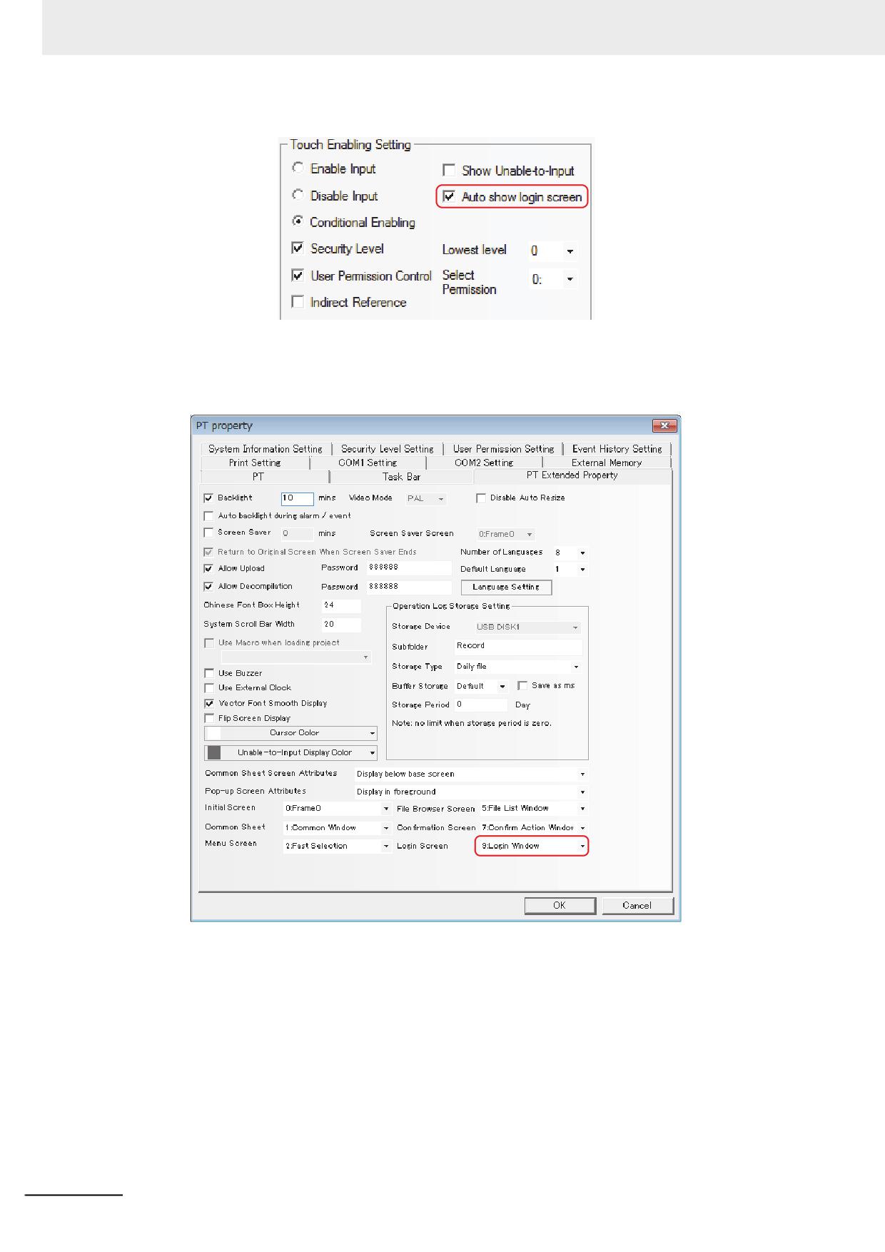
(a) How to set the “Auto show login screen”
Select “Touch Enabling Setting” in [Control Setting] tab in [Properties] dialog box of
control component. Once [Security Level] or [Use Permission Control] is checked,
[Auto show login screen] option will appear, and the “Auto show login screen” check
box is checked, the login screen will pop up automatically.
NB-series Programmable Terminals NB-Designer Operation Manual(V106)
3-409
3 Functions of NB-Designer
(b) Method to specify a screen as “Login Screen”
Setting the corresponding Login Screen in [PT Property] - [PT Extended Properties]
can make the set screen as the “login screen shown automatically” when the Security
Level or Permission Control function is used.
32 FRW, FRB, FRWI, and FRBI memories
FRW, FRB, FRWI and FRBI memories use FLASH to save the data not written frequently.
The data written to the flash memory will not be removed even if the power interruption occurs.
3-410
NB-series Programmable Terminals NB-Designer Operation Manual(V106)
3 Functions of NB-Designer
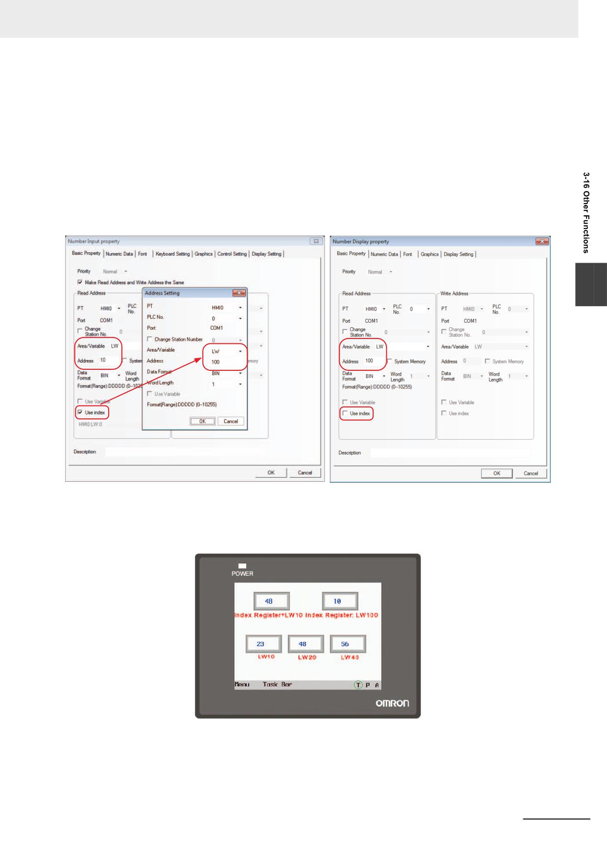
33 Index memory
Index memory realizes the convenient address operation for the user. You can modify the I/O
address of the memory during the machine operation without modifying the edit screen. When
the index memory is selected for the component, the new I/O address of this component = the
value of the index memory + the original I/O address of this component.
For example:
(1) Create a project and place 5 Number Input components in it.
The settings of Number Input component NI0 are as in the lower left figure shown:
The settings of Number Input component NI1 are as in the lower right figure shown:
3
The settings of Number Input components NI2 to NI4 are the same as that of NI1, and their
addresses are LW10, LW20 and LW40 respectively.
(2) Perform the offline test. When the value of index memory is 10, the addresses of NI3 and
NI0 are the same.
NB-series Programmable Terminals NB-Designer Operation Manual(V106)
3-411
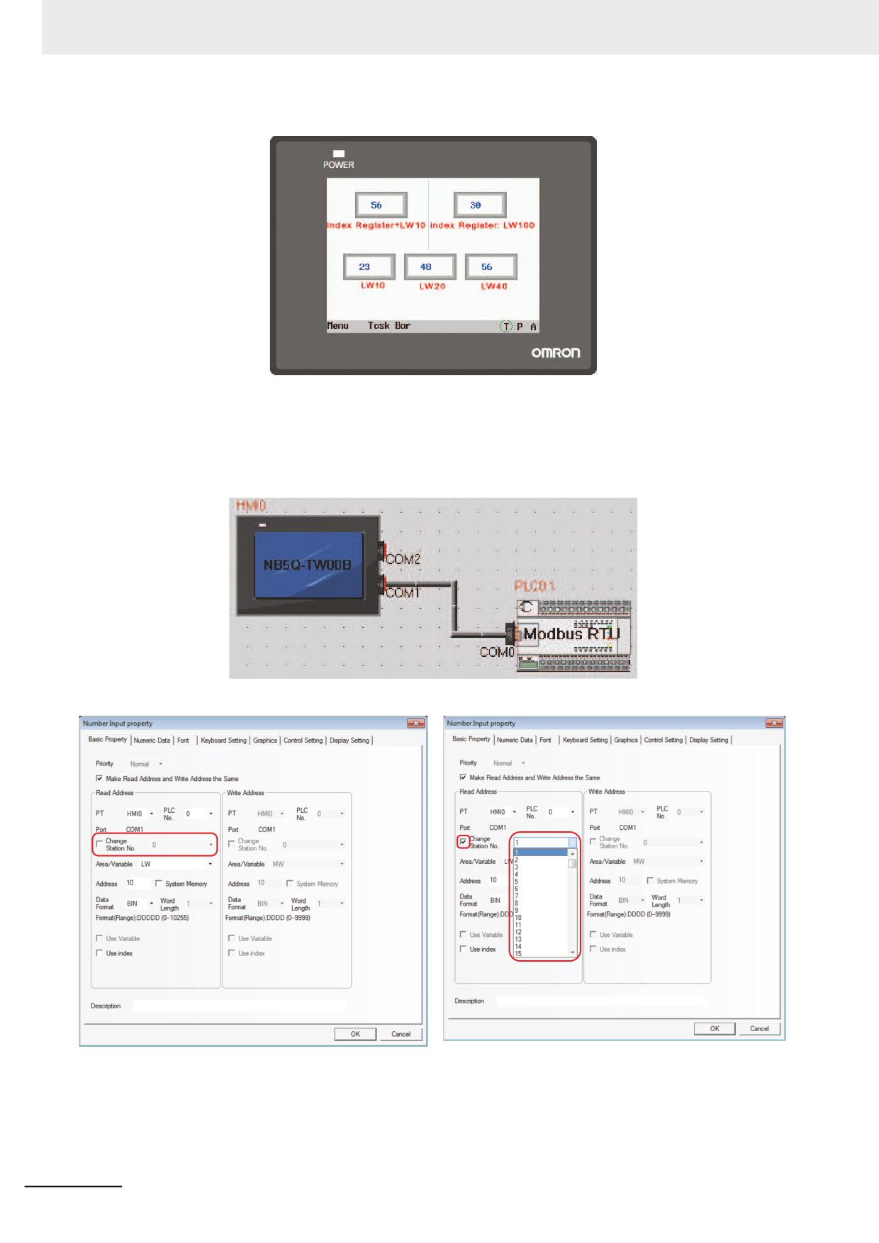
3 Functions of NB-Designer
When the value of index memory is 30, the addresses of NI4 and NI0 are the same.
34 Station Num Index Function
Station number index function is invalid for the backg4round components and Macros.
Only one PLC can be connected with the connection wire, while multiple station numbers can
be set during the editing, thus it is the same effect as the connection with multiple PLCs.
3-412
NB-series Programmable Terminals NB-Designer Operation Manual(V106)
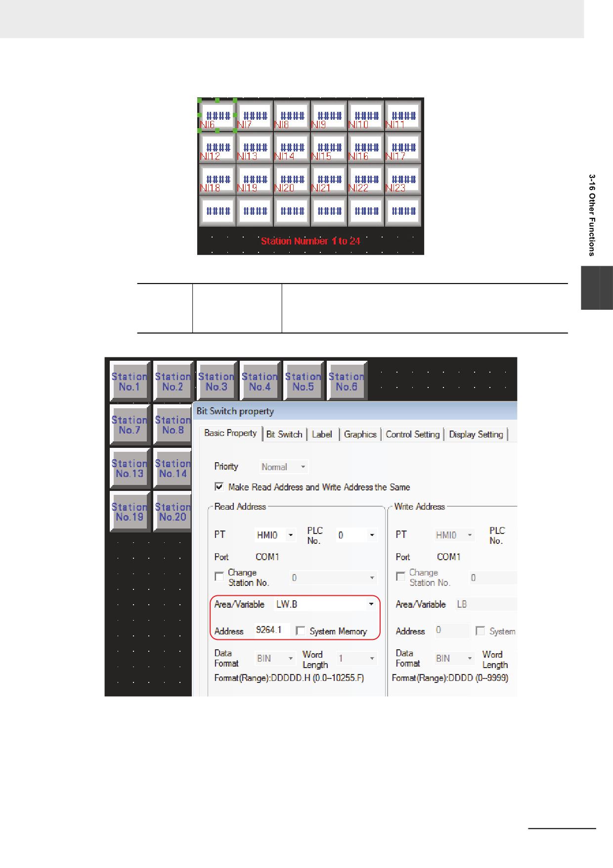
3 Functions of NB-Designer
Test of Mask Station No.
9264~9279
Mask code of PLC
Each bit corresponds to one Station No. of COM 2 (i.e. 9264.0
3
Station No.(COM 2)
corresponds to Station No. 0... and 9279.F corresponds to Station
No. 255). When the bit is turned ON, the communication
corresponding to Station No. will be masked (read/write).
NB-series Programmable Terminals NB-Designer Operation Manual(V106)
3-413
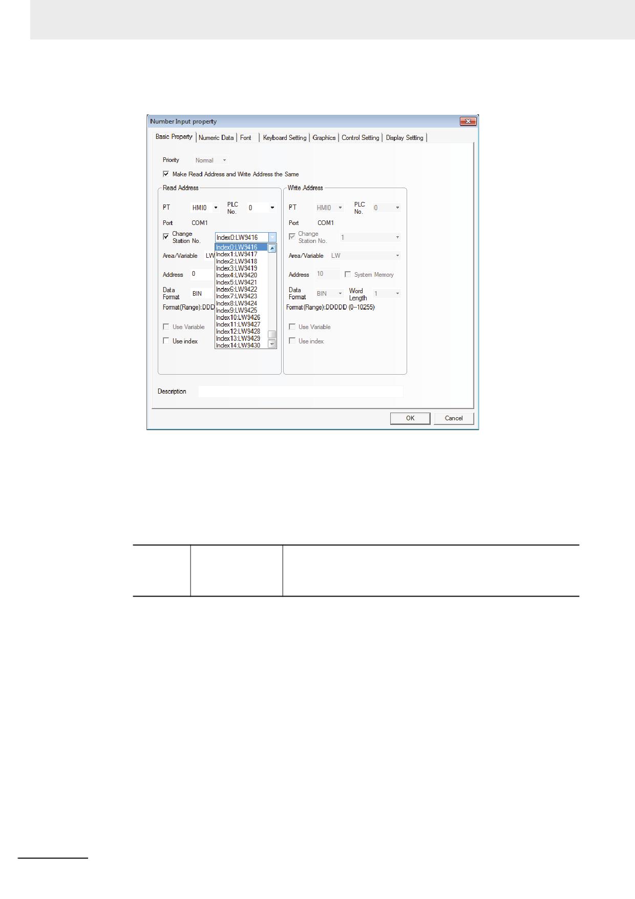
3 Functions of NB-Designer
Station No. use the special memories (LW9416 to LW9431). When the special memories are
used, the Station No. is determined by the value of the memory.
35 PT Mask and PLC Station No. Mask
PT Mask function:
LW9400 to LW9415 (totaling 256 bits) correspond to PT Station No. 0 to 255. When these bits
are set to ON, the access to the corresponding PT numbers will be masked.
PLC Station No. Mask Function:
9264~9279
Mask code of PLC
Each bit corresponds to one Station No. of COM 2 (i.e. 9264.0
Station No.(COM 2)
corresponds to Station No. 0... and 9279.F corresponds to Station
No. 255). When the bit is turned ON, the communication
corresponding to Station No. will be masked (read/write).
3-414
NB-series Programmable Terminals NB-Designer Operation Manual(V106)
3 Functions of NB-Designer
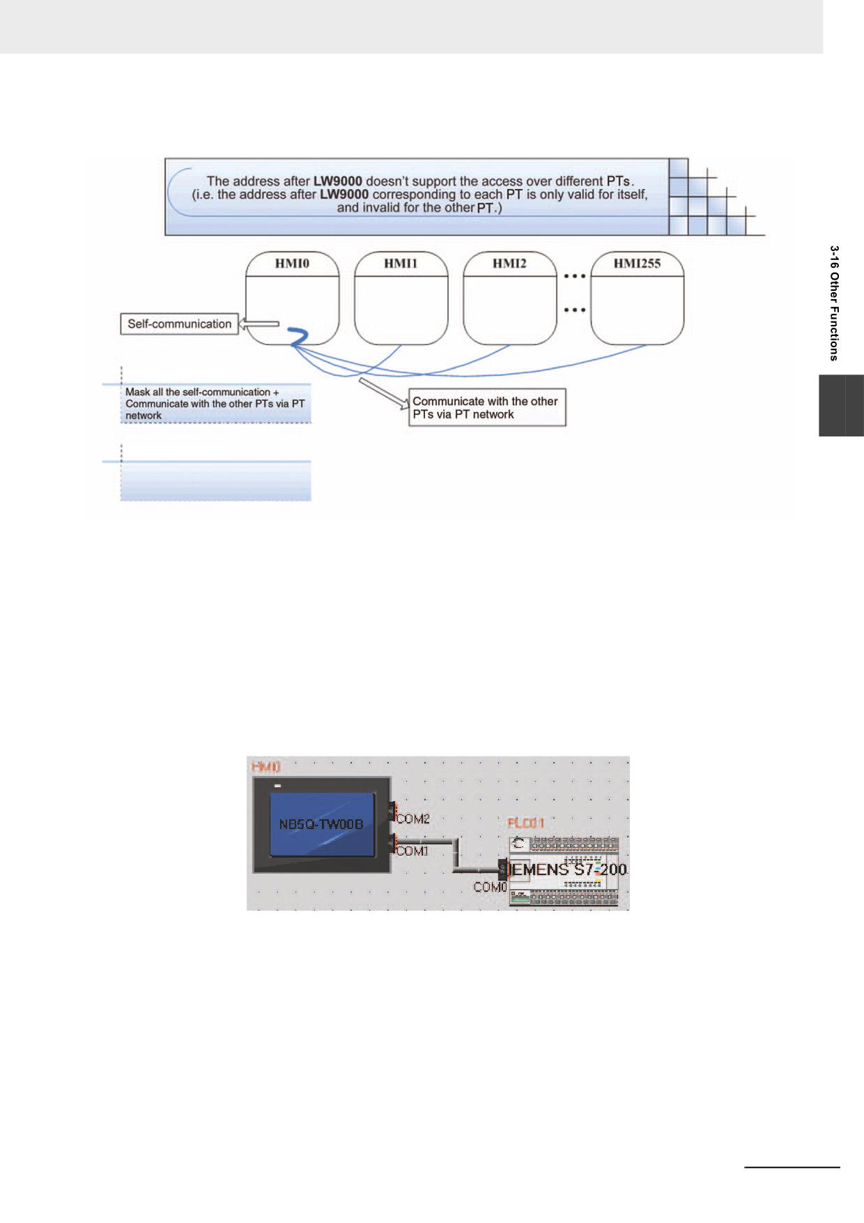
Taking an example the case using masking function for HMI0, the corresponding of LW
memory and masking object is displayed as below.
LW.B 9400.0
3
LW.9264~9279
The communications with the PLC to
connect COM 2 will be being masking.
36 Mask System Prompt Information
NB-Designer provides the system information mask function which is controlled by the special
memories LW9296 (read/write) and each bit corresponds to one piece of system error
information, and the system error information will be masked when the corresponding bits are
set to ON. For example, LW.B9296.2 corresponds to the prompt information “PLC No
Response”.
Note Place Bit Button component and others in the screen which should be being masking of error display and
specify [Set to ON when screen is open] for Type and specify LW.B9296.2 to On.
Take Mask of “PLC No Response” as example
(1) Create one project, and connect NB5Q-TW00B with SIMENS S7-200 for communication.
(2) Place one Number Input component VW0 (One memory in SiemensS7-200) and one Bit
Button component with the address of LW.B9296.2 and Type of “Bit Button” in Edit Window.
(3) Actually, PT0 is not connected with Siemens S7-200 PLC. The prompt information of “PLC
No Response” should appear before, but now the system error prompt information doesn’t
appear for the LW9296 mask function.
NB-series Programmable Terminals NB-Designer Operation Manual(V106)
3-415
3 Functions of NB-Designer
37 How to clear RW area for recipe saving
Clear the address by system memory related RW memory
(1) Set the Read Address to LW9260 and input the starting address objected of clearing RW
area to the Number Input component which is specified the word length to [DWORD].
(2) Set the Read Address to LW9262 and input the word length objected of clearing RW area
to the Number Input component which is specified the word length to [DWORD].
(3) Set LB9130 (PT system memory) to ON and clear the content of RW area.
How to clear values of RW at a time:
(1) Specify this parameter using the [Clear system memory related to RW memory] method. In
order to clear the stored values in RW memory, specify the longest word length of RW
memory to the range from LW9262 to LW 9263.
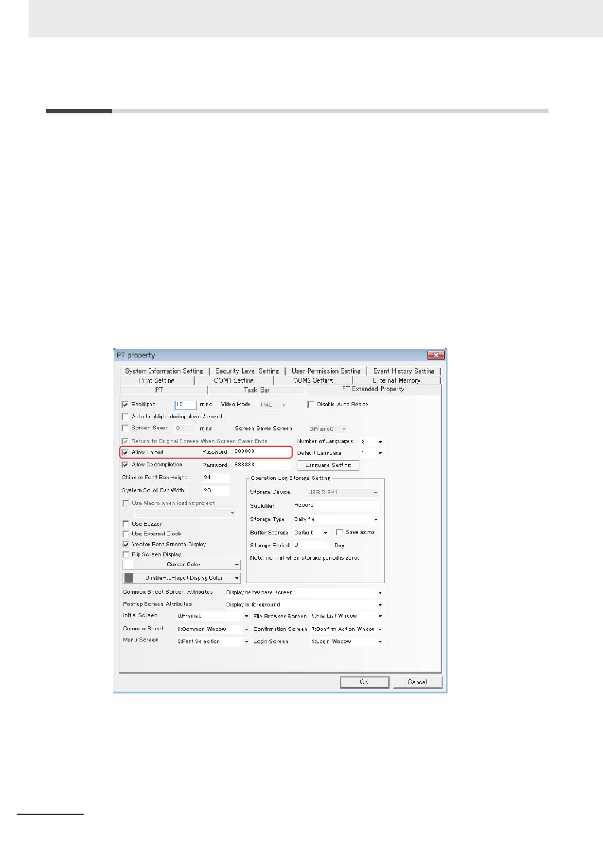
(2) Select “Clear Recipe” in “Select Section” for downloading the NB Manager and click
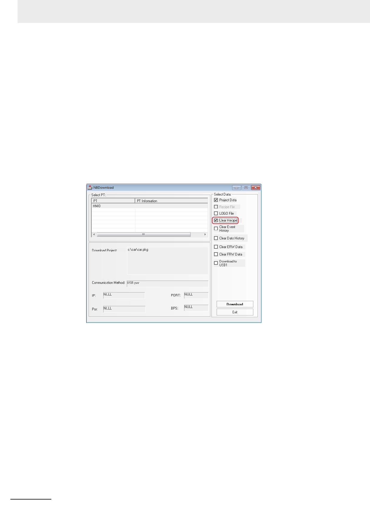
“Execute”.
(3) Check the [Clear Recipe] check box during the download.
38 Data Encryption
For the data stored in the CSV format in the external memory, data encryption function can be
used to restrict the modification, edition, and others by the user.
Note 1
If the [Decompile] operation is not performed to the CSV file generated for the component using [Data
Encryption], the illegible characters will be displayed in the opened CSV file.
2
If the [Decompile] operation is performed through the NB-Designer, the CSV file can only be opened for
viewing instead of modifying or editing.
3
If the encrypted file is modified by someone intentionally, the error prompt will appear during the [Decom-
pile] operation in NB-Manager, making the damage of source file informed to the user.
4
The components supporting [Data Encryption] function are Data Log, XY Graph and Data History compo-
nents.
5
When the data encryption is set, the display of the component is also encrypted.
Take the setting method of [Data Encryption] for sampling data file of the Data Log as example:
3-416
NB-series Programmable Terminals NB-Designer Operation Manual(V106)
3 Functions of NB-Designer
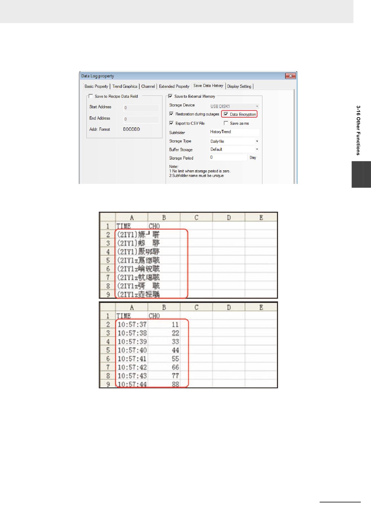
(1) Check the [Data Encryption] option after the [Save to External Device] option is checked in
the [Save Data History] tab in the [Data Log Property] dialog box.
3
(2) The illegible characters will be displayed in the generated CSV file after the encryption if it
is directly opened.
Using the [Data Encryption] function
Not using the [Data Encryption]
function
NB-series Programmable Terminals NB-Designer Operation Manual(V106)
3-417
3 Functions of NB-Designer
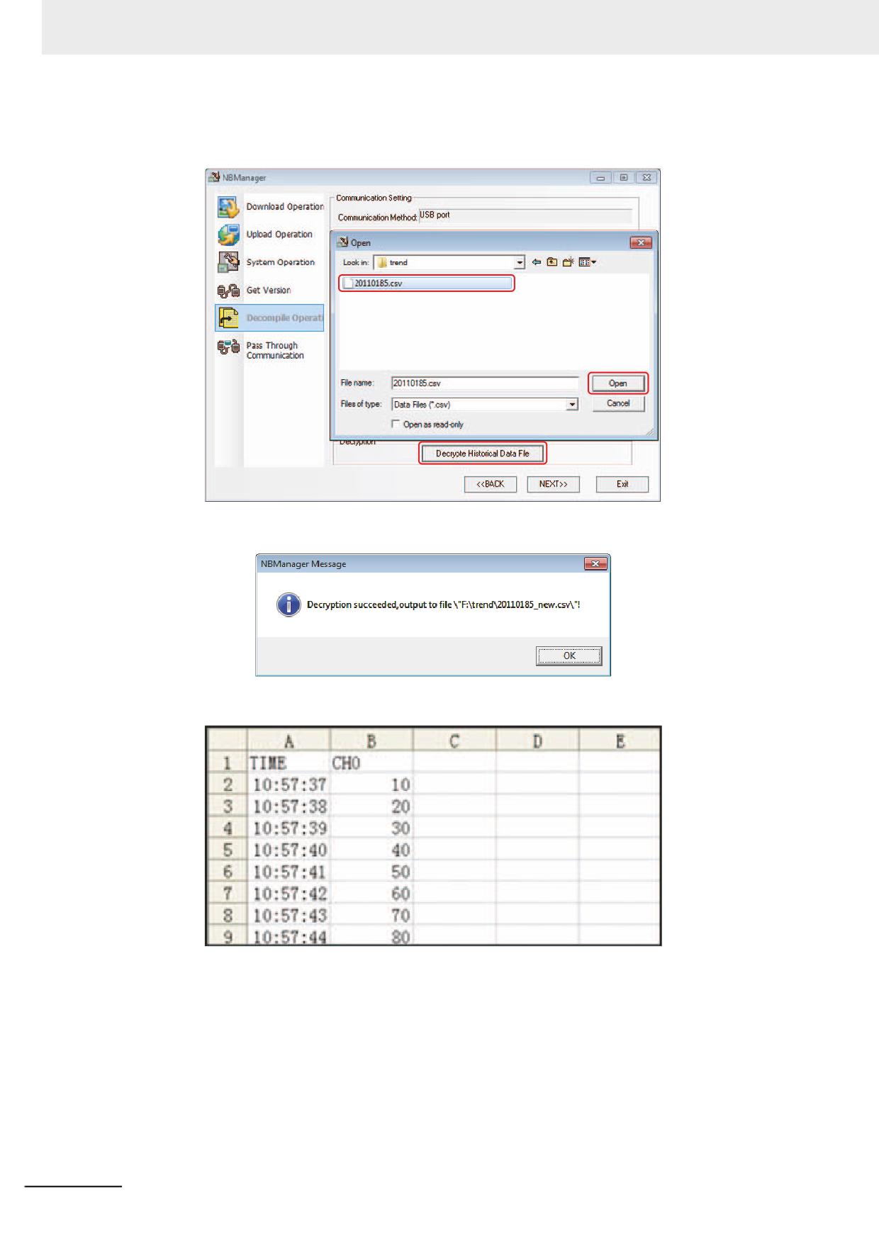
(3) The procedure of decompiling the CSV file by using the [Decompile] function of NB-
Manager is as shown below:
The following dialog box will pop up after the successful decryption.
The display effect of the CSV file decrypted successfully is as shown below.
3-418
NB-series Programmable Terminals NB-Designer Operation Manual(V106)
3 Functions of NB-Designer
• VNC Server
VNC server is used to monitor and operate the display status of the NB Unit from the PC connected
through Ethernet. For settings, refer to 3-10-1 PT (Page 3-291).
A VNC client should be installed in landscape orientation. You cannot place an NB unit in vertical
orientation.
To use VNC server function, make the connection from the PC with the following settings.
Server: IP Address of the NB Unit
Password: The value set in PT property setting
Port: 5900
This function can be performed in several modes by combining system memories.
Operation mode: Screens can be monitored and operated from remote locations. To change to
operation mode, turn OFF LB9291 and turn ON LB9292 while operating in monitor
mode.
3
Monitor mode: Screens can be only monitored from remote locations, but not operated.
To change to monitor mode, turn ON LB9291 and LB9293 while operating in operation
mode.
Additional Information
This function can be enabled or disabled by changing the value of LB9290 on the NB Unit.
Operational conflict may occur if a remote operation is attempted while an on-site operation is
already being performed. Also, screen, which is not intended by the on-site operator, may
appear. For the connection, careful consideration must be given to the on-site situations.
NB-series Programmable Terminals NB-Designer Operation Manual(V106)
3-419
3 Functions of NB-Designer
3-17 RecipeEditor
Description of RecipeEditor Function
RecipeEditor is an Editor attached in the NB-Designer, and it is mainly used for the user to check,
edit or create the recipe file conveniently and visually. The supported formats currently are as
follows: files in .rcp format uploaded from or downloaded to NBManager, the specific files in .csv
format, the file of FRW memory in .frp format, and the file of ERW memory in .erp format.
The Recipe Editor supports the functions as below.
The following functions are supported currently:
(1) Display the data in recipe file.
(2) Modify the data in recipe file.
(3) Import the CSV file in specific format, and export the recipe data as the CSV file in specific
format.
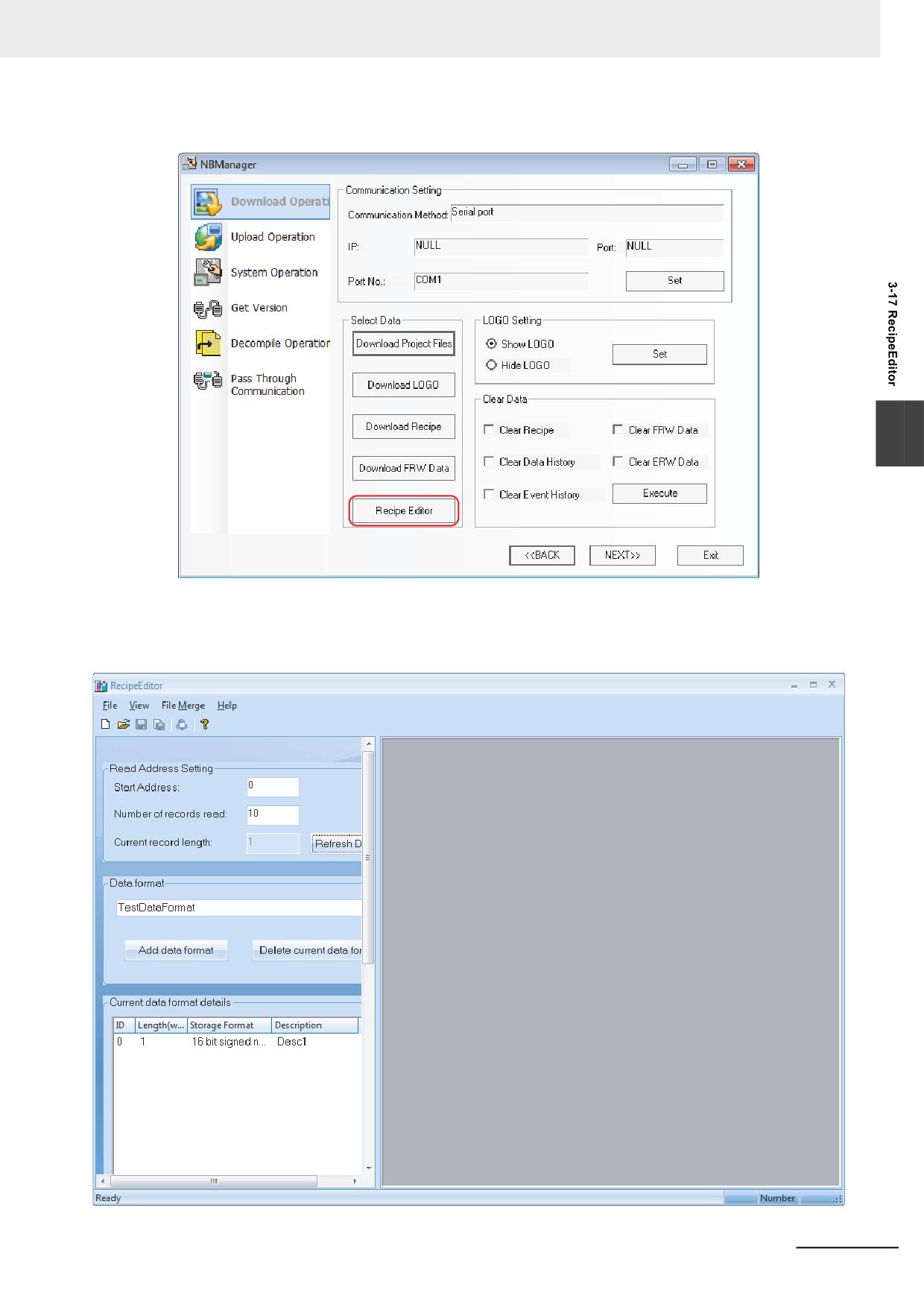
Method of calling RecipeEditor
(1) Click Recipe Editor in the Tools menu in NB-Designer software.
3-420
NB-series Programmable Terminals NB-Designer Operation Manual(V106)
3 Functions of NB-Designer
(2) Click [Recipe Editor] in Download Operate tab of NBManager screen.
3
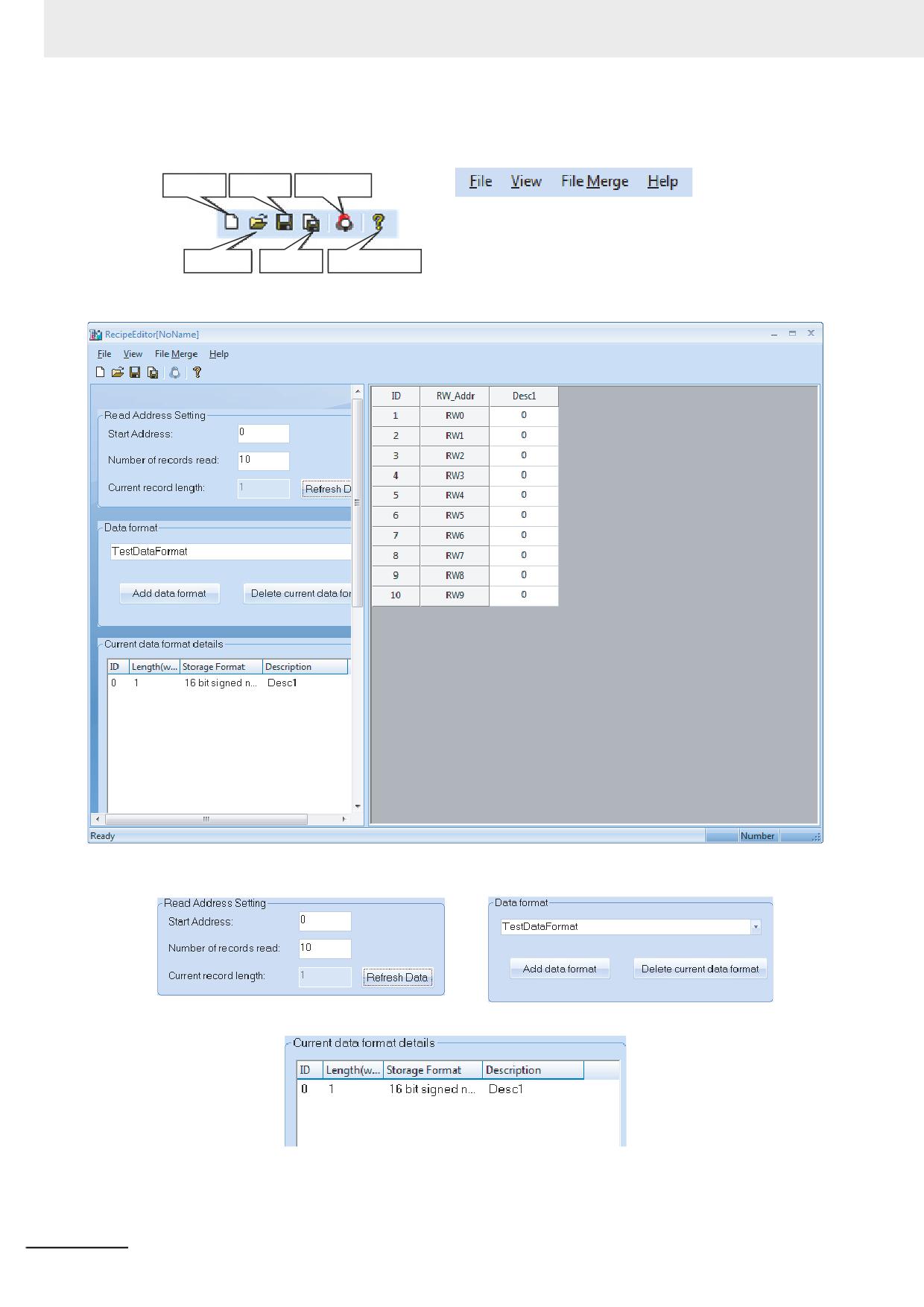
Introduction of RecipeEditor Screen
The screen corresponding to the initial operation of program is as shown below:
NB-series Programmable Terminals NB-Designer Operation Manual(V106)
3-421
3 Functions of NB-Designer
• Toolbar and Menu Bar
New
Save
Binary Browser
Open
Save as
Version Information
Click New, then the initial screen will pop up as below.
• “Read Address setting” area, “Data Format” area and “Current data format details” area
3-422
NB-series Programmable Terminals NB-Designer Operation Manual(V106)
3 Functions of NB-Designer
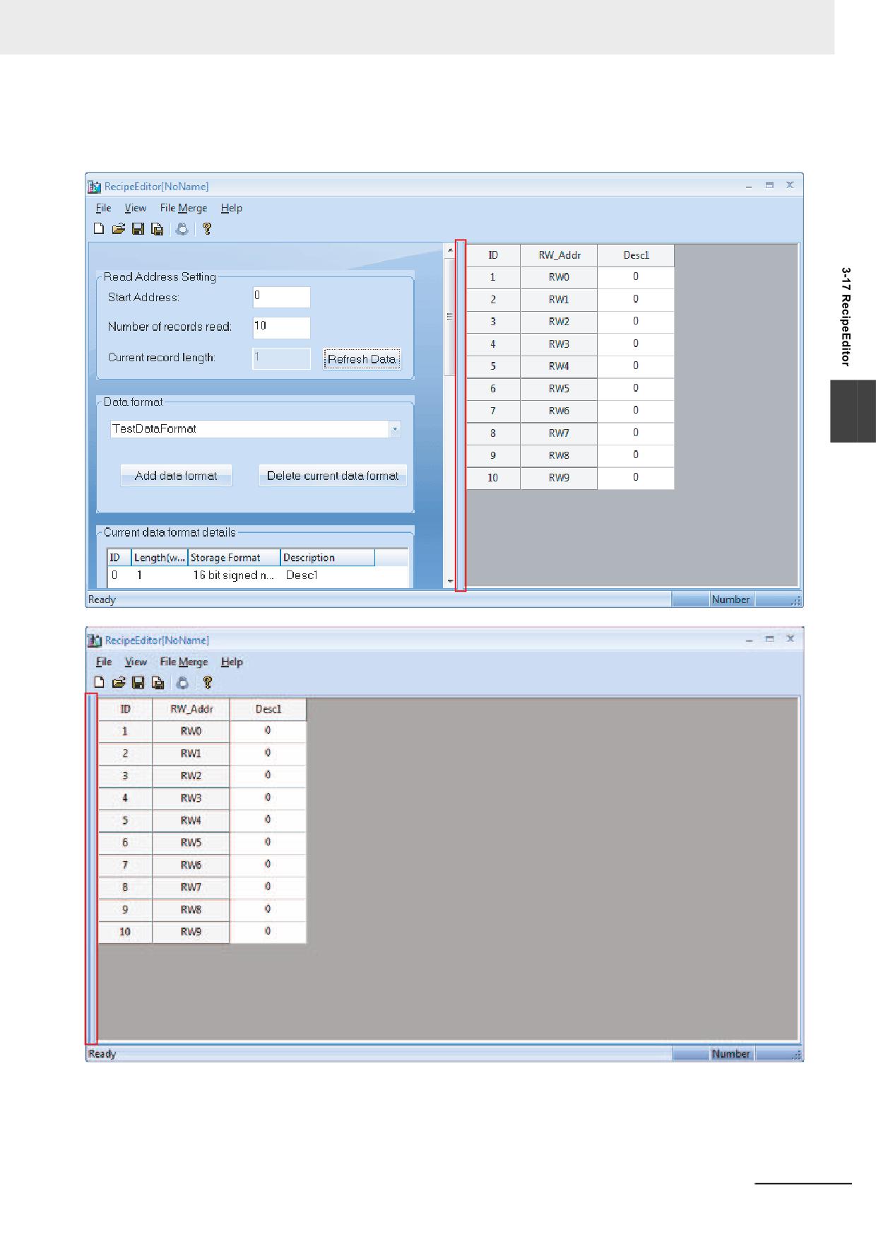
The red frame is the boundary of the setting area and data area, and the former is in the left side while
the latter is in the right side. Move the cursor to this boundary and click it, then the setting area will be
hidden, and if you click it again, the setting area will appear again.
3
NB-series Programmable Terminals NB-Designer Operation Manual(V106)
3-423
3 Functions of NB-Designer
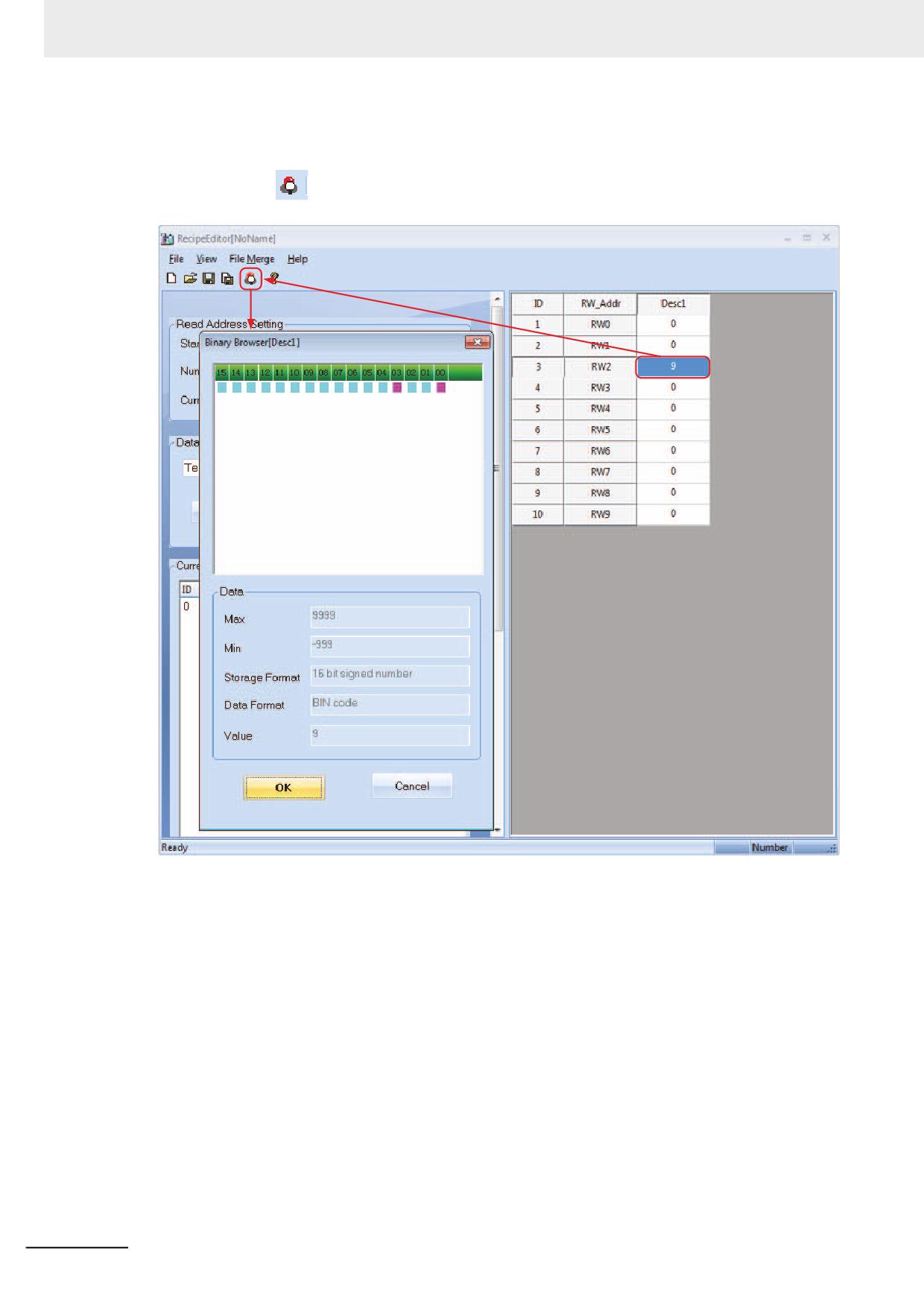
• Input Data in Data Area and Binary Browser
Directly input data in data area and right-click the mouse in the address where the bits to be
browsed or click
(Binary Browser) icon to perform the bit browsing with selected the address
which should be checked the state of the bit.
In this case, the value of RW2 is 9, and bit addresses of 03 and 00 indicate the status of ON in
binary browser.
3-424
NB-series Programmable Terminals NB-Designer Operation Manual(V106)
3 Functions of NB-Designer
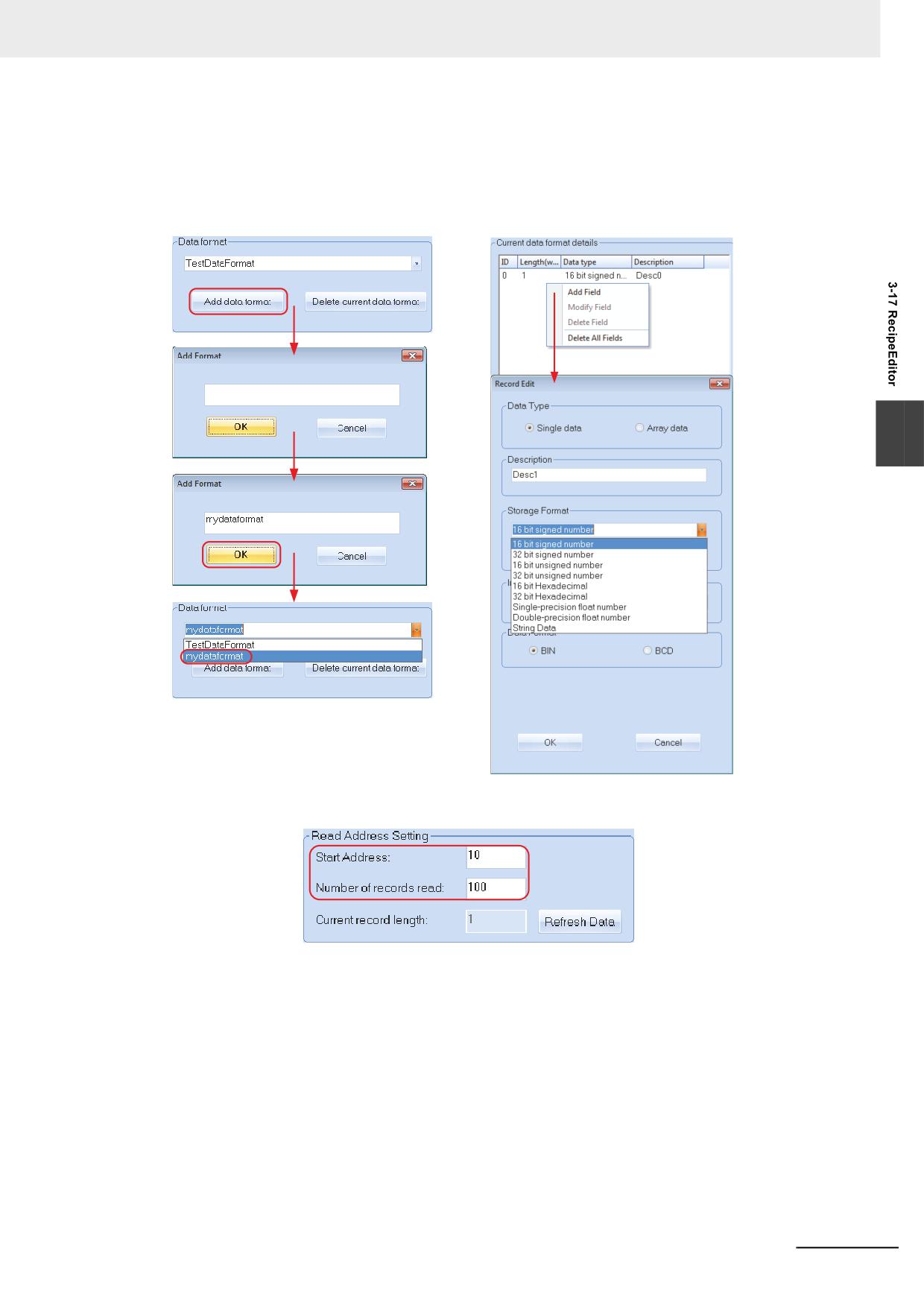
Usage of RecipeEditor
1
Add Data format, Data Type and Adjustment of Data Start Address and Data Length
Procedure of Adding Data Format
Procedure of Adding Data Type
3
Adjustment of Data Start Address and Data Length
NB-series Programmable Terminals NB-Designer Operation Manual(V106)
3-425
3 Functions of NB-Designer
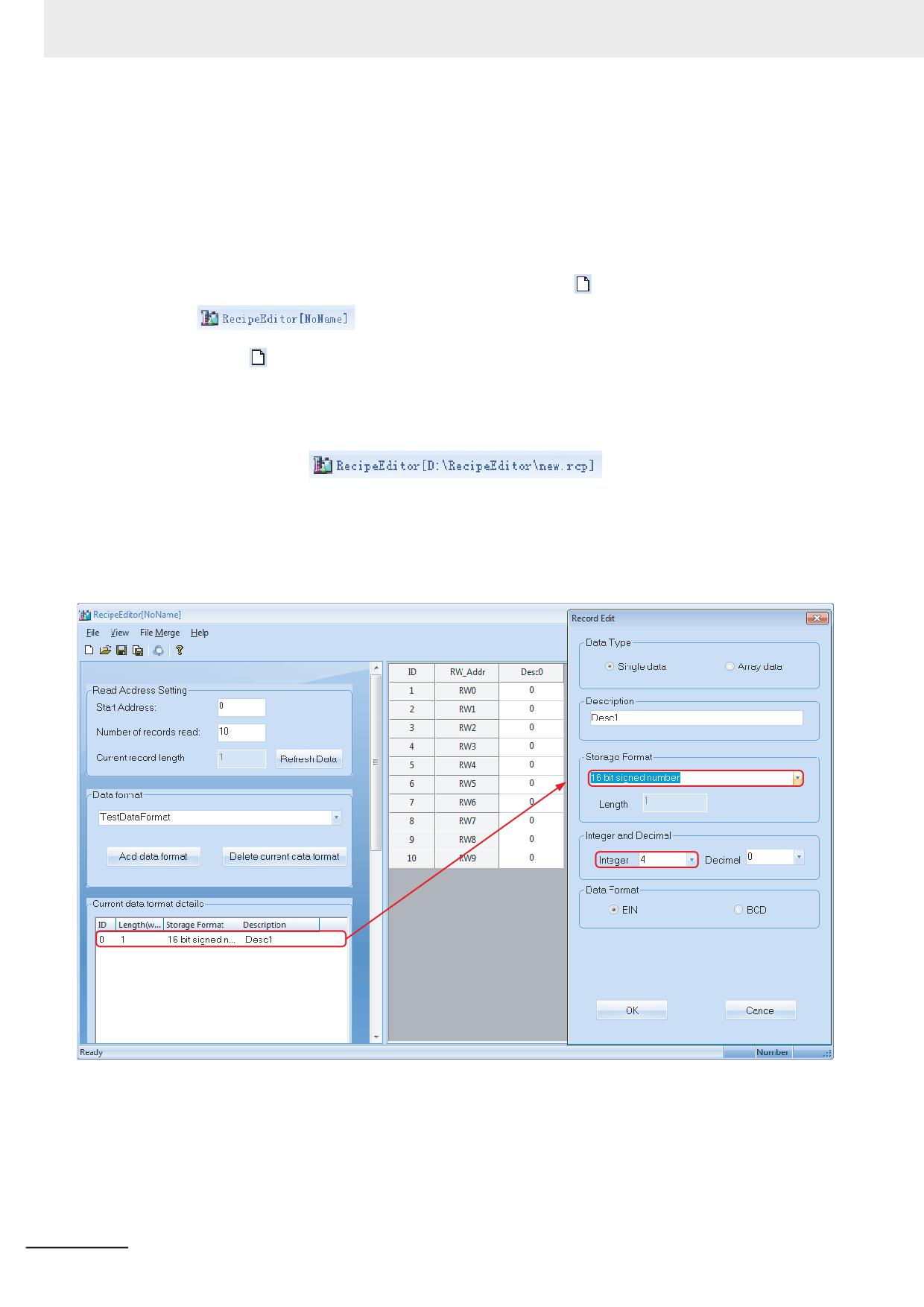
2
Creating new Recipe file and Saving the file
When new Recipe file is created, the data type is needed to be specified. When the existing
Recipe file is read, the file's specification should be corresponded to the data type specified to
the file. If the file is specified the different data type, the contents of the file cannot be read
correctly.
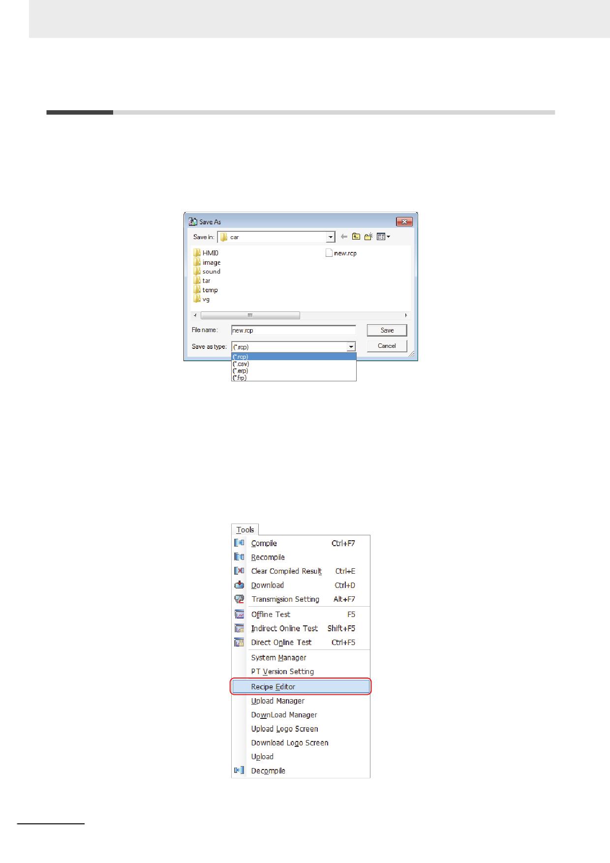
The available file format to be edited by Recipe file are .rcp, .frp and .csv.
When RecipeEditor is opened for the first time, clicking
(New) icon will make
displayed in the title bar; while Save As dialog box will pop up if
clicking
(New) icon after the creation of recipe file. Therefore, create another recipe file only
after the previous created file is saved. When opening the Recipe file, if [File] - [Open] is
selected in the state of the file is already opened, [Save as] dialog box will be opened and
[Open file] dialog box will be displayed. For the already saved files, the complete file path will
appear in the title bar.
3
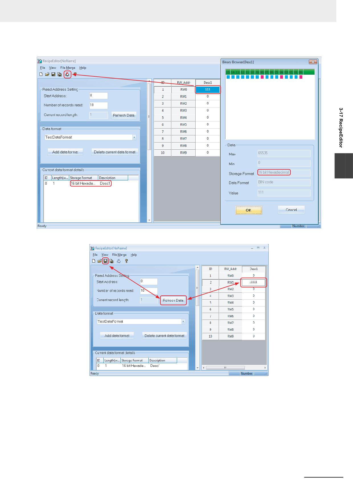
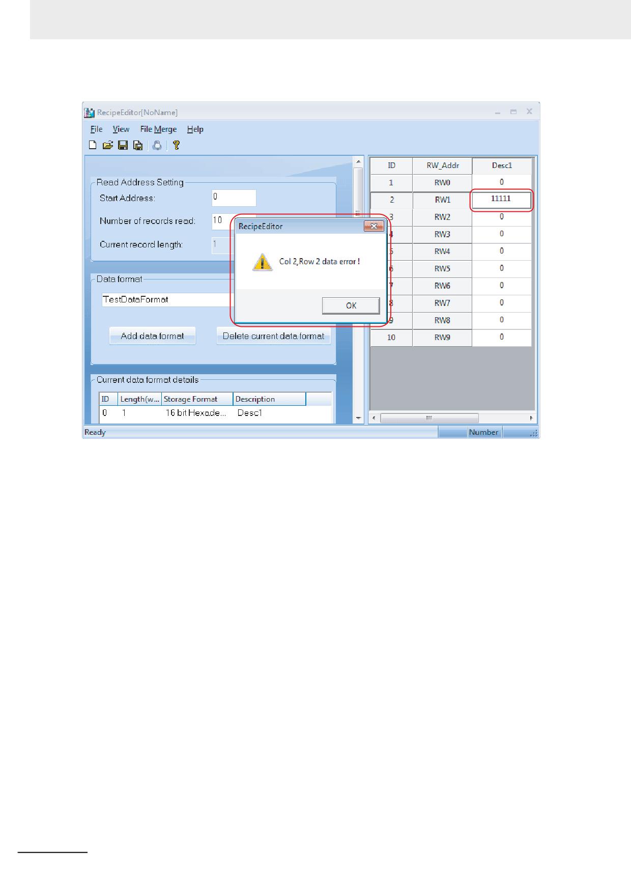
Data type and changing data
For example, double-click the mouse at the red box during the edition to make the Record Edit
Dialog pop up, and then change Storage Format from “16 bit signed number” as the lower left
graphics shown to “16 bit Hexadecimal” as the lower right graphics shown.
3-426
NB-series Programmable Terminals NB-Designer Operation Manual(V106)
3 Functions of NB-Designer
3
NB-series Programmable Terminals NB-Designer Operation Manual(V106)
3-427
3 Functions of NB-Designer
After the completion of number input, it would better to have the Enter key pressed, and it must
be saved.
If the file is not saved and click the [Update Data] button, the data which was entered before
clicking the button will be lost.
The value exceeds the data type and range of digits cannot be input.
4
Single data and Array data.
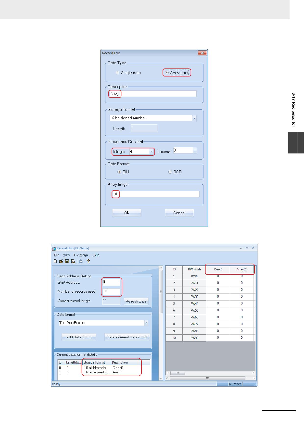
The data shown in the previous case is single data, i.e. a group of data. Provide a brief of array
data. Array data, i.e. the data belonging to the same classification is placed together, which is
helpful to the data edition, as shown below:
3-428
NB-series Programmable Terminals NB-Designer Operation Manual(V106)
3 Functions of NB-Designer
3
NB-series Programmable Terminals NB-Designer Operation Manual(V106)
3-429
3 Functions of NB-Designer
5
File Merge Function.
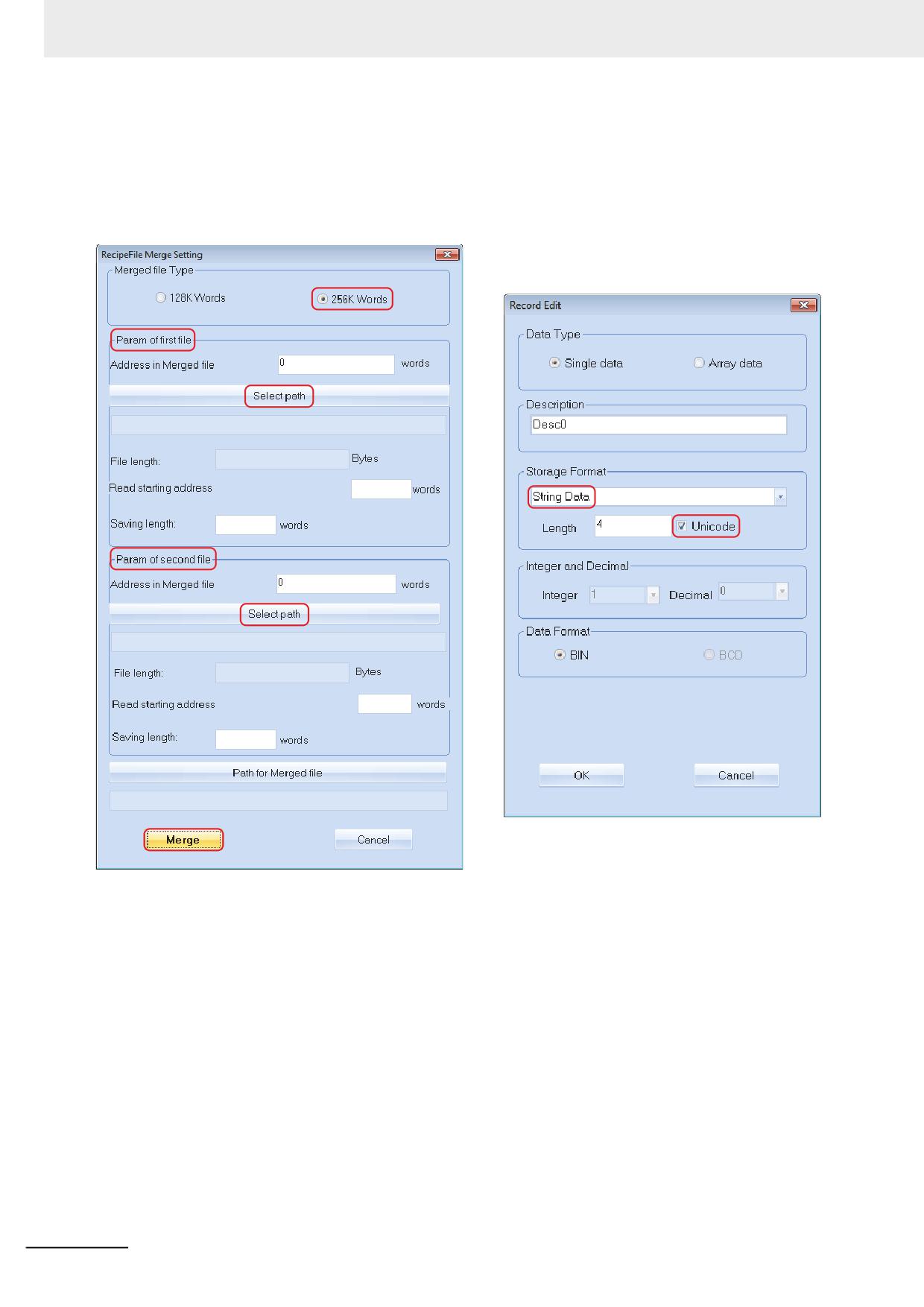
File merge function is mainly applicable to the 2 recipe files with the different recipe addresses.
These 2 recipe files can be merged into 1 file after they are edited separately, then the 1
merged file can be downloaded into PT, as the lower left graphics shown:
6
Unicode can be checked for String Data.
As the above right graphics shown, Unicode can be checked for String Data.
3-430
NB-series Programmable Terminals NB-Designer Operation Manual(V106)
3 Functions of NB-Designer
7
Part of data type supports Binary Browser
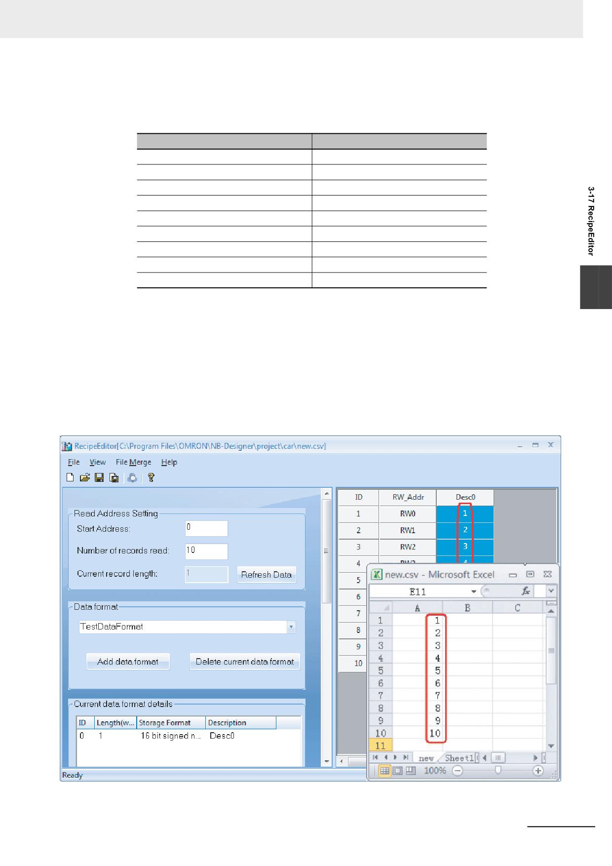
Binary Browser is one special function provided by RecipeEditor, which is convenient for the
user to check the data which is shown as “Supported”, as shown below:
Data Type
Supported or Not
16 bit signed number
Supported
32 bit signed number
Supported
16 bit unsigned number
Supported
32 bit unsigned number
Supported
16 bit Hexadecimal
Supported
32 bit Hexadecimal
Supported
Single-precision float number
Not supported
Double-precision float number
Not supported
String Data
Not supported
3
3 Data Types (.rcp, .frp and .csv)
.rcp format
This is the recipe file format which can be identified by PT. The recipe file in this format can be
uploaded or downloaded with NBManager. (The size of this file is limited by the recipe memory in PT
device.)
.frp format
This is the file format to be stored in Flash memory of PT.
.csv format
The data can be edited by Excel.
NB-series Programmable Terminals NB-Designer Operation Manual(V106)
3-431
3 Functions of NB-Designer
3-432
NB-series Programmable Terminals NB-Designer Operation Manual(V106)
4
Functions of NBManager
This section describes the NBManager.
4
4-1
Introduction of NBManager
4-2
4-2
Download Operation
4-3
4-2-1
Communication Setting
4-3
4-2-2
Select Data
4-6
4-2-3
LOGO Setting
4-9
4-2-4
Clear Data
4-10
4-3
Upload Operation
4-12
4-4
System Operation
4-15
4-5
Get Version
4-17
4-6
Decompile Operation
4-18
4-7
Pass Through Communication
4-19
4-8
Web Interface Operation
4-21
NB-series Programmable Terminals NB-Designer Operation Manual(V106)
4-1
4 Functions of NBManager
4-1
Introduction of NBManager
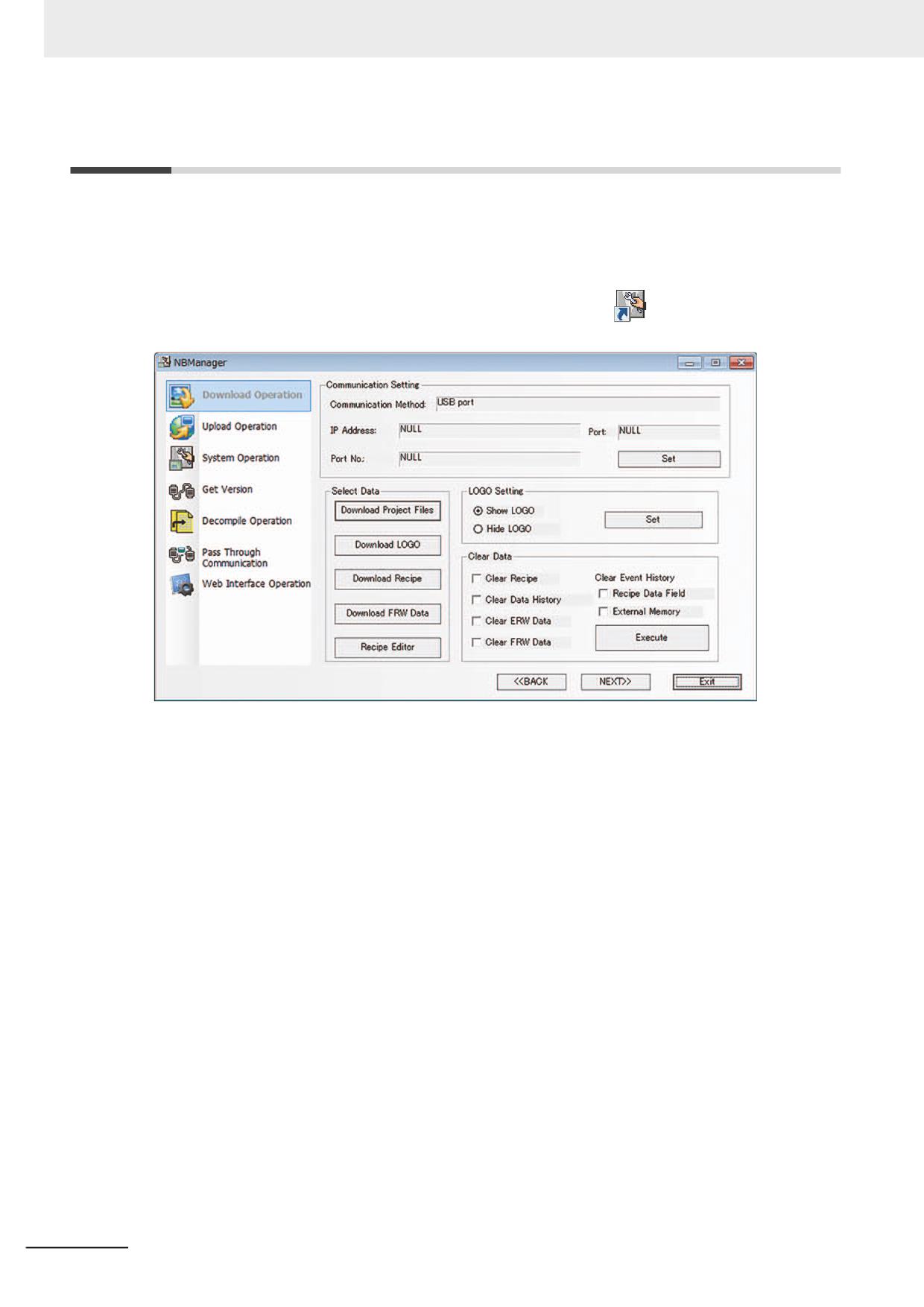
NBManager is a tool managing the whole NB-Designer software, which includes 6 operates, i.e.
Download Operation, Upload Operation, System Operation, Get Version, Decompile Operation and
Pass Through Communication.
Clicking [Start]-[All Programs]-[OMRON]-[NB-Designer]-[Tools]-[NBManager] will make NBManager
dialog box pop up, as shown below. Double-clicking the shortcut icon (
) on desktop also allows the
NBManager to start.
4-2
NB-series Programmable Terminals NB-Designer Operation Manual(V106)
4 Functions of NBManager
4-2
Download Operation
Download Operation is mainly used for the download from PC to PT.
The Communication Setting must be set before the download.
4-2-1
Communication Setting
The setting of Communication Setting is the same with the settings of project options in the edit
window. For details, refer to 3-15 Download (Page 3-362).
Communication Setting
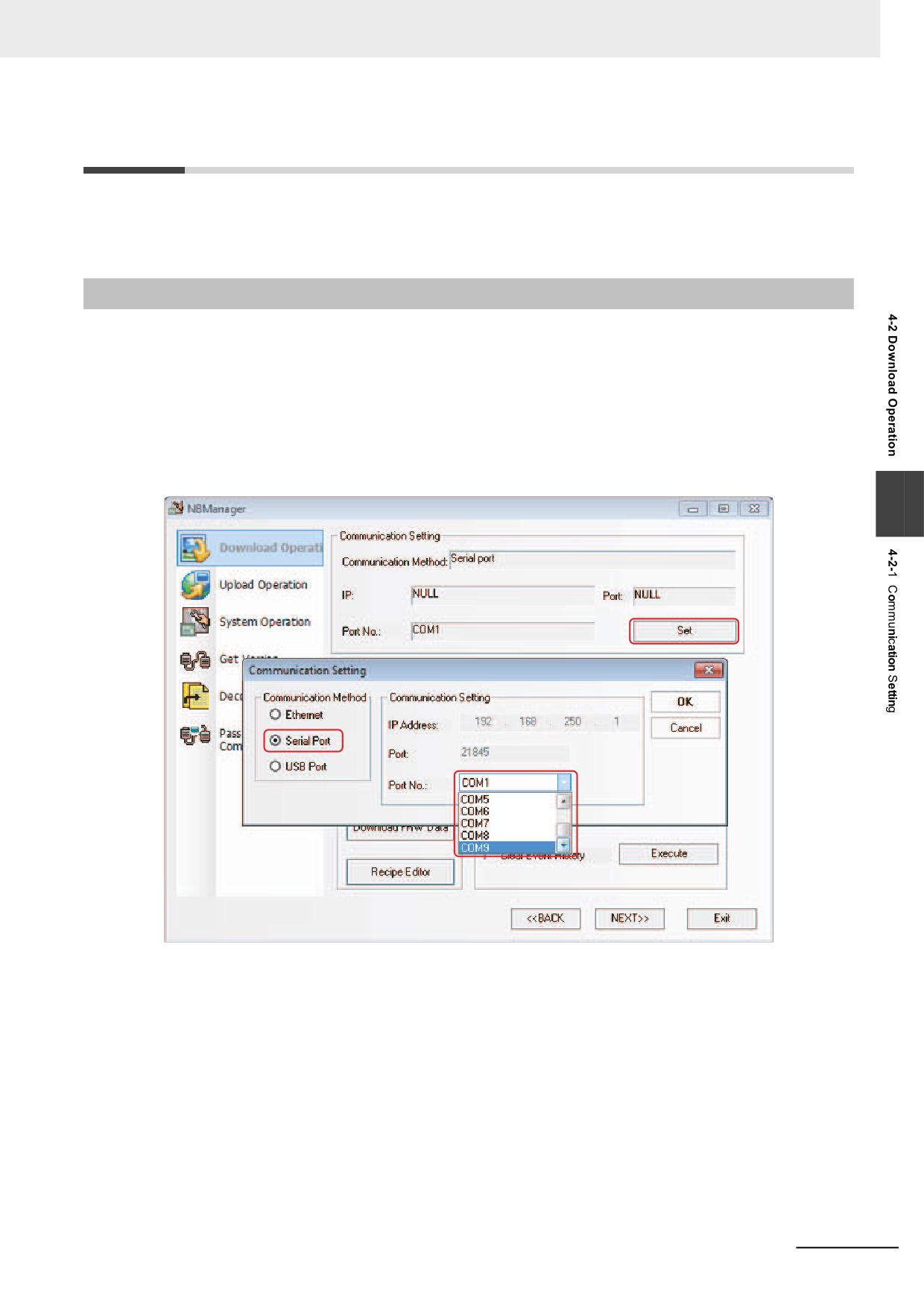
• The Communications Type with Serial Port
Click the [Set] button and select [Serial Port] and the Serial Port of your PC from [Serial No.] in the
popup [Communication Setting] dialog box, then click the [OK] button.
4
NB-series Programmable Terminals NB-Designer Operation Manual(V106)
4-3
4 Functions of NBManager
• The Communications Type with USB
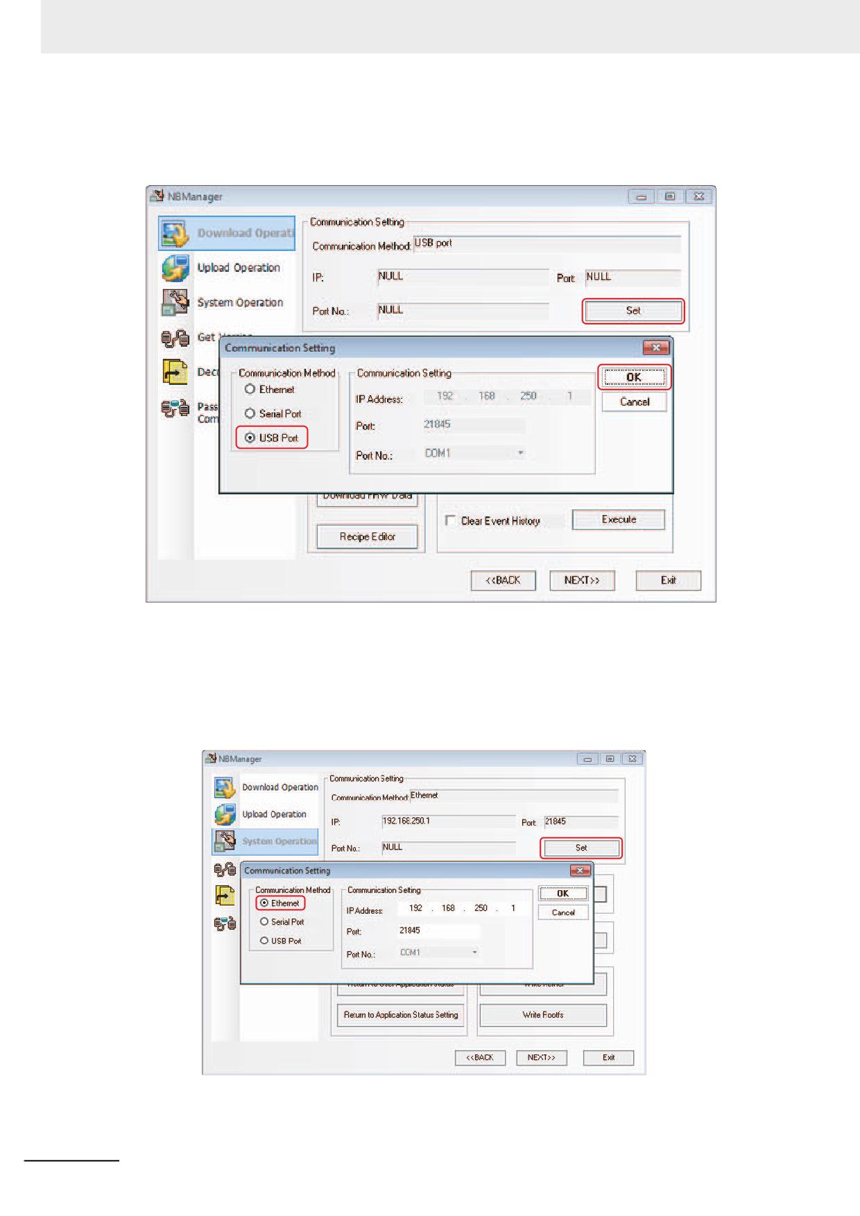
USB Port is the system default type. If you use the USB to perform the download, it doesn’t need to
make settings again.
• The Communications Type with Ethernet
• Settings for using Ethernet
In the [NBManager] dialog box, click the [Set] button in the [Communication Setting] option, and
then check the [Ethernet] in Communication Method option in the Communication Setting dialog
box with the various parameters same as that of PT Unit. At the same time, set the IP address of
PC to the same network segment as that for PT Unit, as shown below:
4-4
NB-series Programmable Terminals NB-Designer Operation Manual(V106)
4 Functions of NBManager
• Setting and obtaining IP address and Port
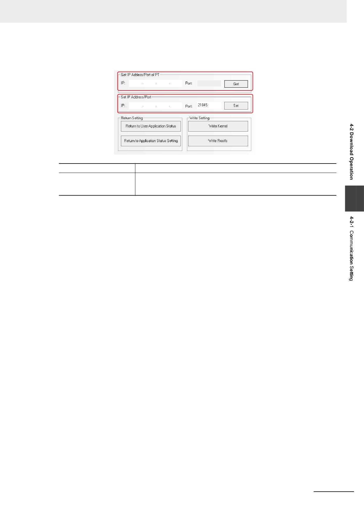
In the [NBManager] dialog box, click the [System Operate].
Get IP Address/Port of PT
Obtain IP address and port number of PT.
Set IP Address/Port of PT
Modify the IP address and Port of PT to the parameters which were set to [IP]
and [Port]. (IP Address/Port can be updated only when the connection is realized
via USB port or serial port.)
4
After setting of the Communication Setting, move to the settings of Select Data.
NB-series Programmable Terminals NB-Designer Operation Manual(V106)
4-5
4 Functions of NBManager
4-2-2
Select Data
The operation is the same as the one of edit window. For details, refer to 3-15 Download (Page 3-362).
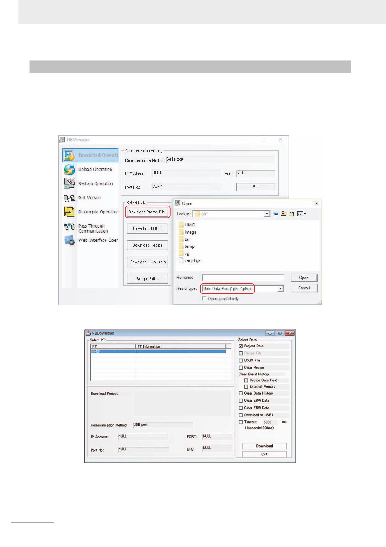
Download Project Files: Refers to download the edited project files (*.pkg/pkgx) to the PT.
The pkg file is project data for NB-TWB.
The pkgx file is project data for NB-TWB-V1.
Click the [Download Project Files] button:
Select the generated *.pkg/pkgx file after compiling the edited project file, then click the [Open] button
to make the following dialog box pop up.
If there are several PTs in your project, firstly select the No. corresponding to the destination PT to be
downloaded, and then click the [Download] button.
4-6
NB-series Programmable Terminals NB-Designer Operation Manual(V106)
4 Functions of NBManager
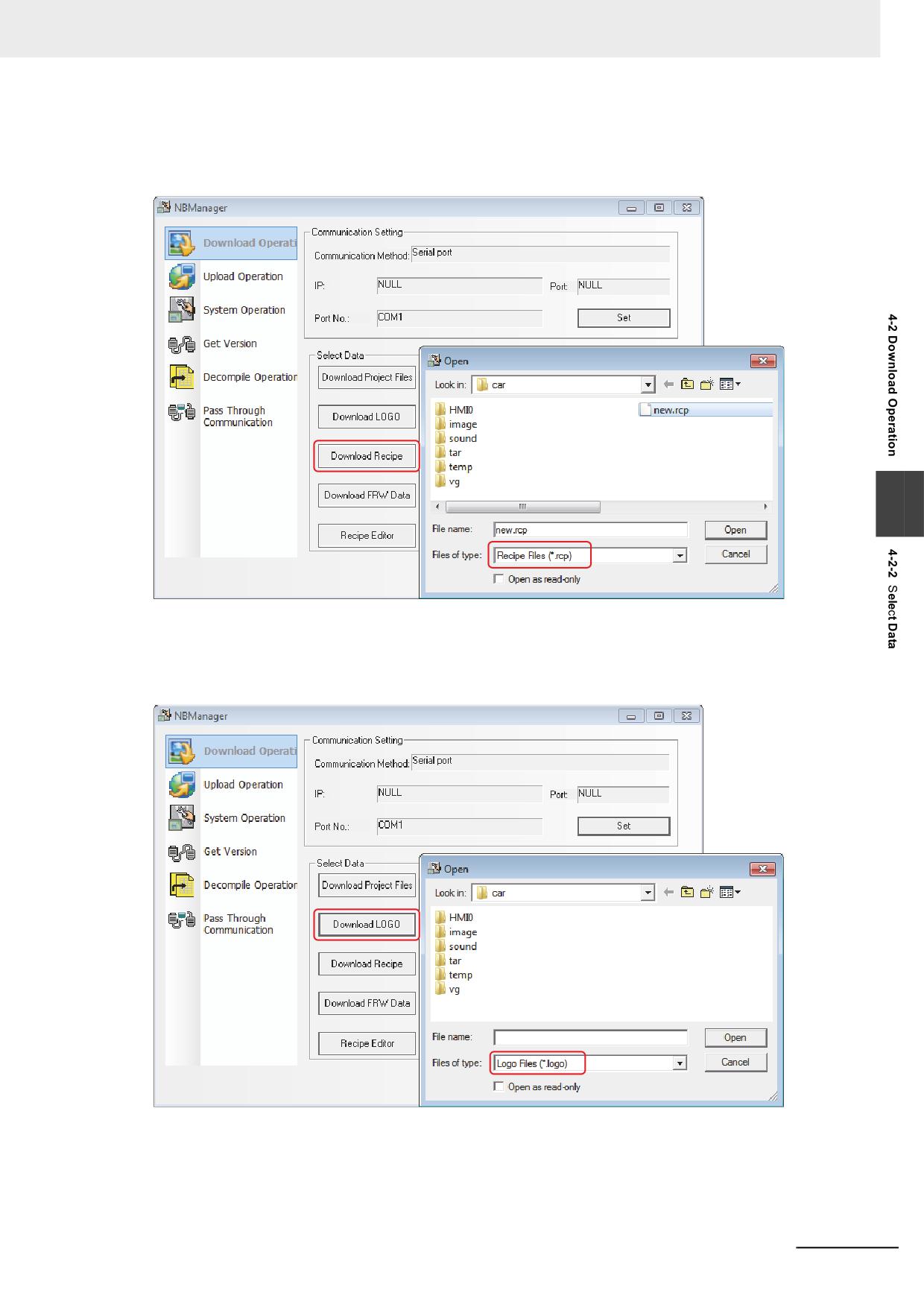
Download Recipe
Firstly, click the [Download Recipe] button and select the pre-edited file with the suffix of “.rcp”, then
click the [Open] button to perform the download.
4
Download LOGO
Click the [Download LOGO] button and select the edited project, i.e. the file with the suffix of “*.logo”
in PT folder under “car” folder, and then click the [Open] button to perform the download.
NB-series Programmable Terminals NB-Designer Operation Manual(V106)
4-7
4 Functions of NBManager
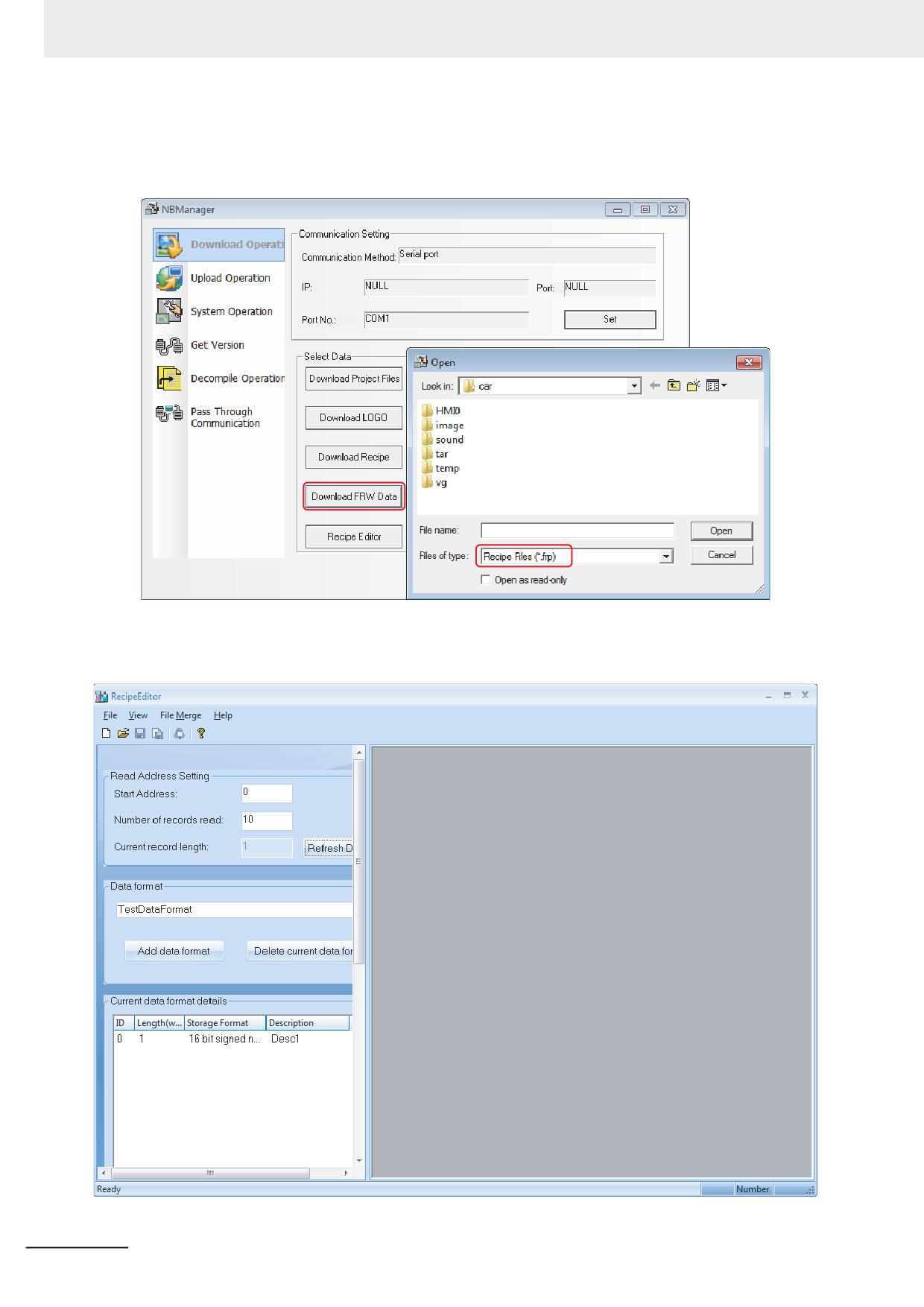
Download FRW Data
Click the [Download FRW Data] button and select the edited project, i.e. the file with the suffix of
“*.frp” in PT folder under “car” folder, and then click the [Open] button to perform the download.
Recipe Editor
Clicking the [Recipe Editor] button will open the RecipeEditor.
4-8
NB-series Programmable Terminals NB-Designer Operation Manual(V106)
4 Functions of NBManager
4-2-3
LOGO Setting
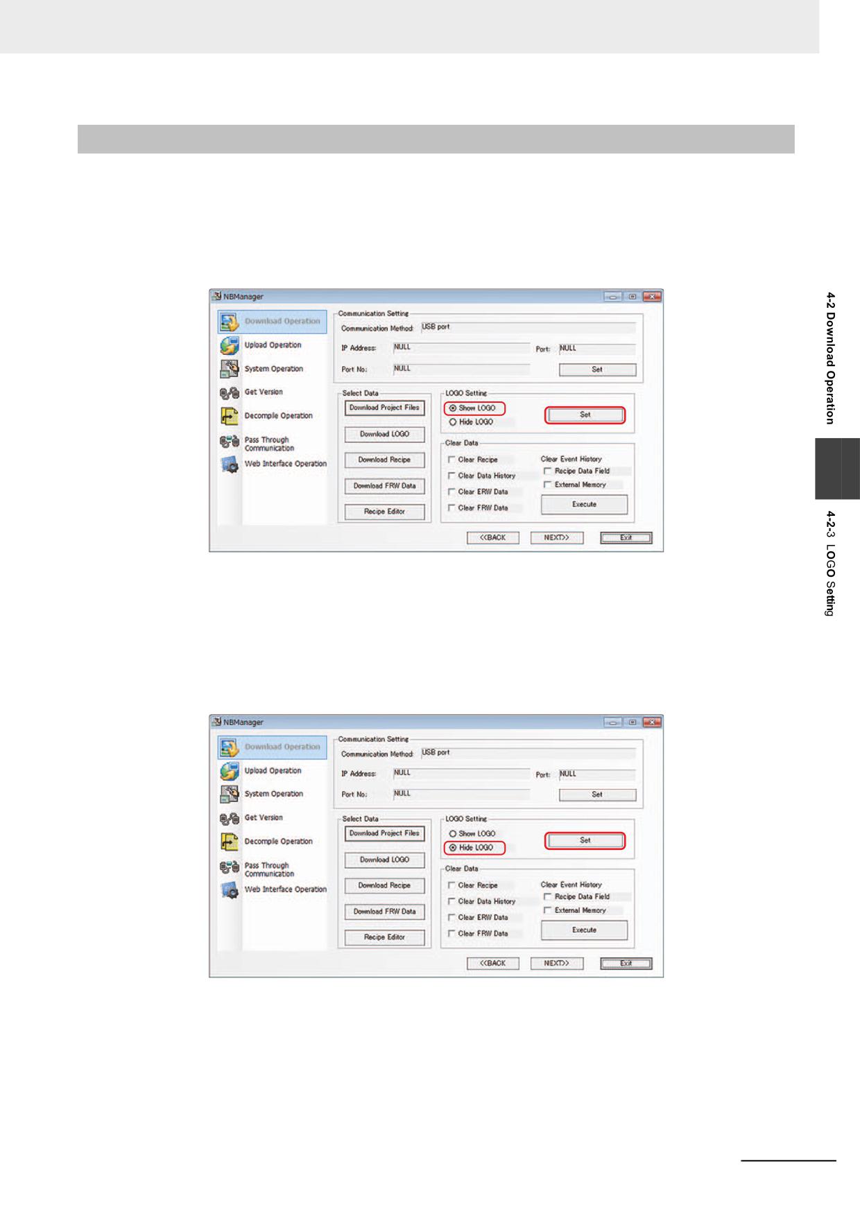
It is used to set the display of LOGO screen at the PT startup.
Show LOGO
The specific operation is as follows: Select [Show LOGO] and click the [Set] button as shown below.
If the setting is successful, [Set Successfully] dialog box will appear. Once the setting is successful,
The transfered LOGO screen will be displayed at the next startup of PT.
4
If the setting is failed, please modify the Communication Setting again after the “Error occurs” dialog
box pops up.
Hide LOGO
The specific operations are as follows: Select [Hide LOGO] and click the [Set] button as shown
below. If the setting is successful, [Set Successfully] dialog box will appear. Once the setting is suc-
cessful, LOGO screen will not appear during the startup of PT next time.
NB-series Programmable Terminals NB-Designer Operation Manual(V106)
4-9
4 Functions of NBManager
If the setting is failed, please modify the Communication Setting again after the “Error occurs” dialog
box pops up.
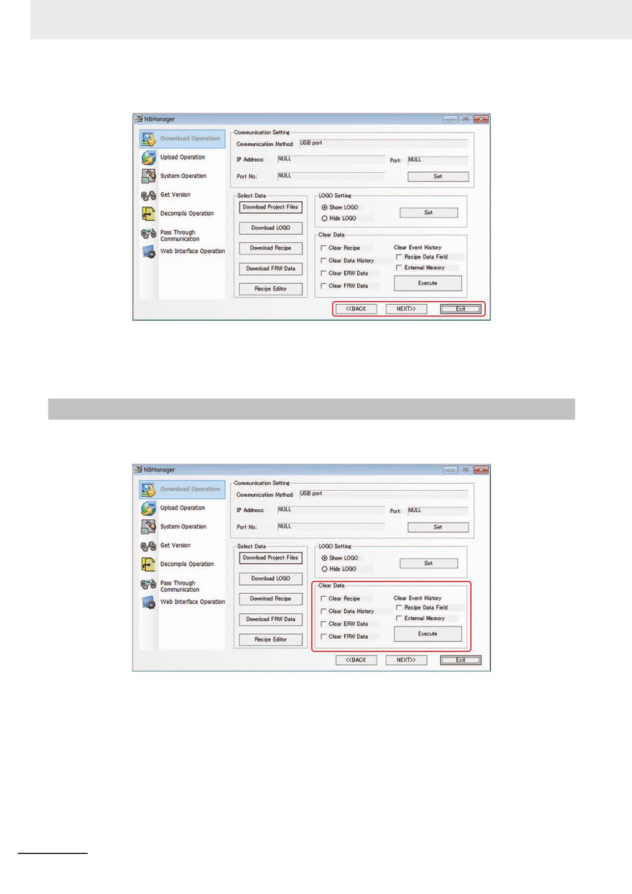
Clicking the [BACK] and [Next] buttons can make switching among the Download Operate, Upload
Operate, System Operate, Get Version, Decompile Operate and Pass Through Communication.
Click the [Exit] button to exit from the NBManager.
4-2-4
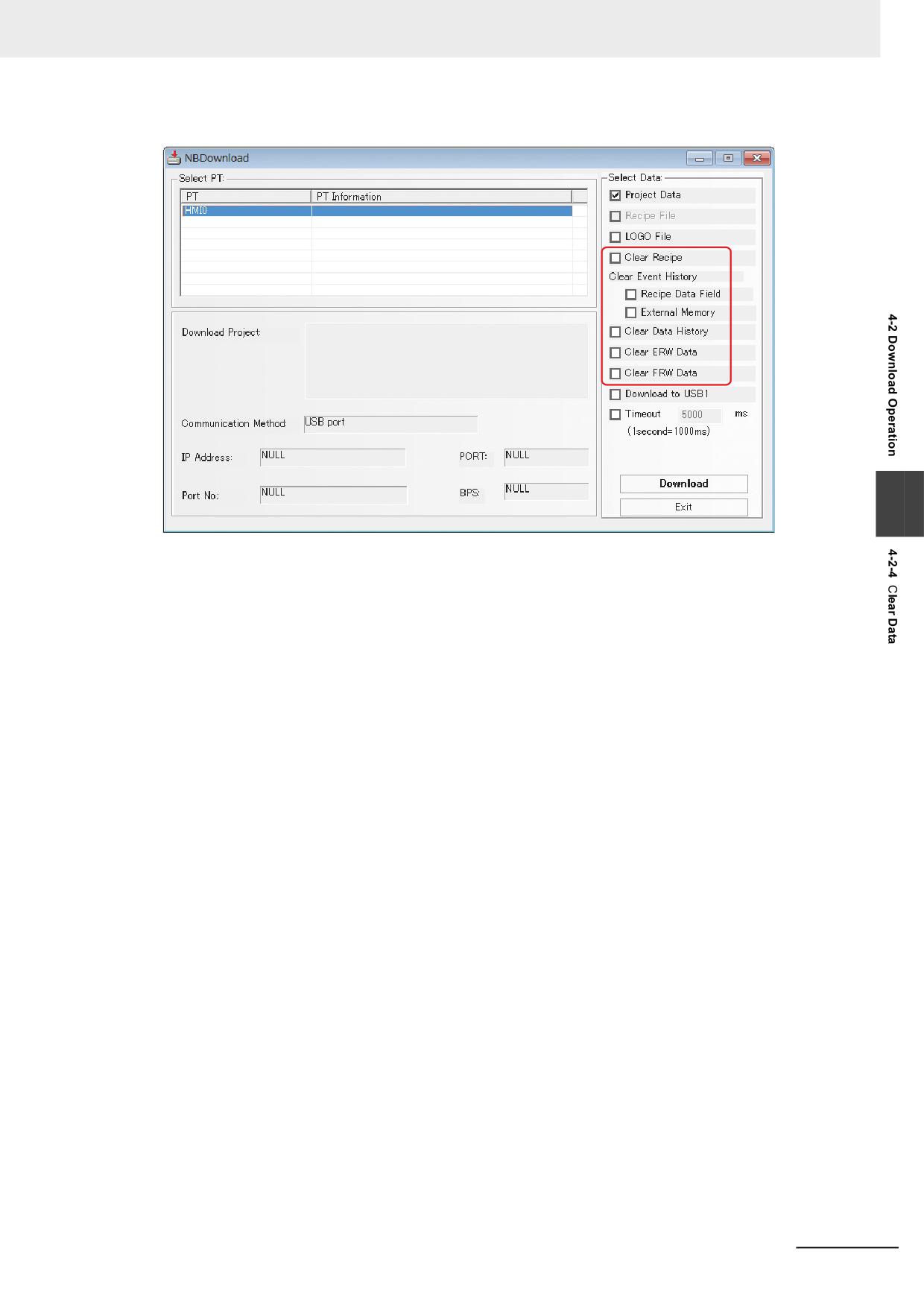
Clear Data
The option in Clear Data are consistent with the corresponding options in “Select Section” of NB-
Designer. After checking the required options, press the [Execute] button.
4-10
NB-series Programmable Terminals NB-Designer Operation Manual(V106)
4 Functions of NBManager
4
NB-series Programmable Terminals NB-Designer Operation Manual(V106)
4-11
4 Functions of NBManager
4-3
Upload Operation
Upload Operate is mainly used for the file upload from PT to PC.
The communication parameters must be set before the upload.
The Communication Setting is same as that of download.
Select Data:
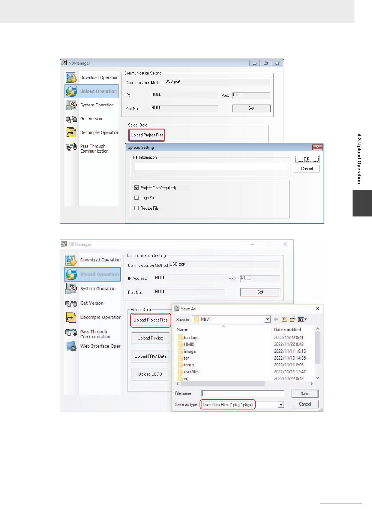
Upload Project Files:
Enter descriptions to [PT Information], if necessary.
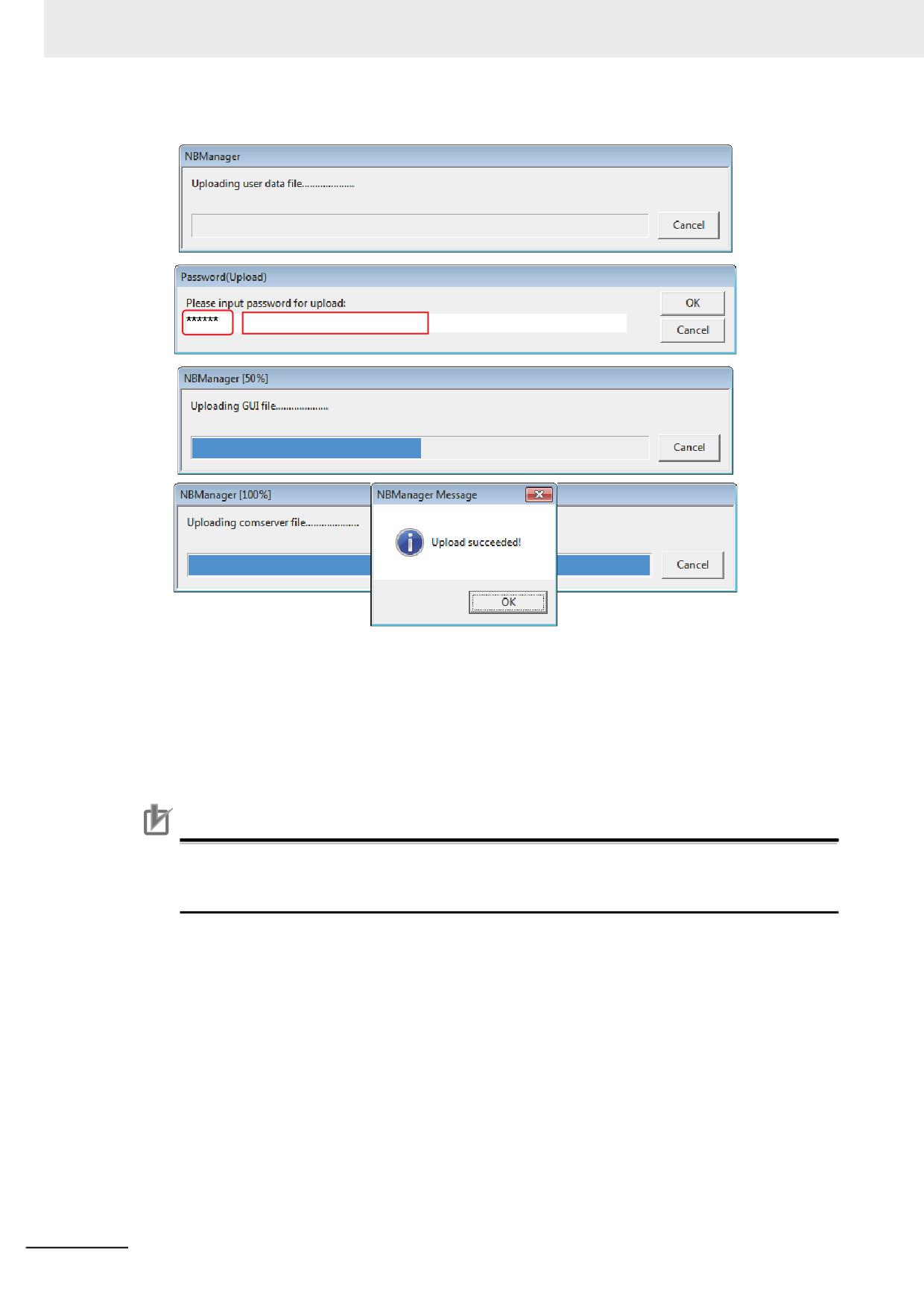
Firstly check [Project Data (required)] and click the [OK] button to select the path for saving the data,
then click the [Save] button after inputting the file name.
After the [Password(Upload)] pops up, input 888888 and press the OK button to perform the upload.
Note The default password for upload is 888888.
If you want to modify the upload password, please double-click the PT in Project Work Space and
modify [Password] corresponding to “Allow Upload” in [PT Extended Properties] tab.
4-12
NB-series Programmable Terminals NB-Designer Operation Manual(V106)
4 Functions of NBManager
When Logo file and recipe file need to be uploaded, you can check “Logo File” and “Recipe File”.
4
NB-series Programmable Terminals NB-Designer Operation Manual(V106)
4-13
4 Functions of NBManager
Default password is 888888
Select [Upload Recipe] and select the path to save the recipe, and then click the [Save] button after the
file name is input.
Select [Upload LOGO] and select the path to save the LOGO, then click the [Save] button after the file
name is input.
Select [Upload FRW] and select the path to save the FRW, and then click the [Save] button after the
File name is input.
The file name and the path saved during the upload can be selected by the user freely.
Precautions for Correct Use
Uploading the data that created with NB-Designer version 1.34 or earlier using NB-Designer ver-
sion 1.35 or later may fail. Upload the data with NB-Designer version 1.34 or earlier and decom-
pile it first. Then open it again in NB-Designer version 1.35 or later.
4-14
NB-series Programmable Terminals NB-Designer Operation Manual(V106)
4 Functions of NBManager
4-4
System Operation
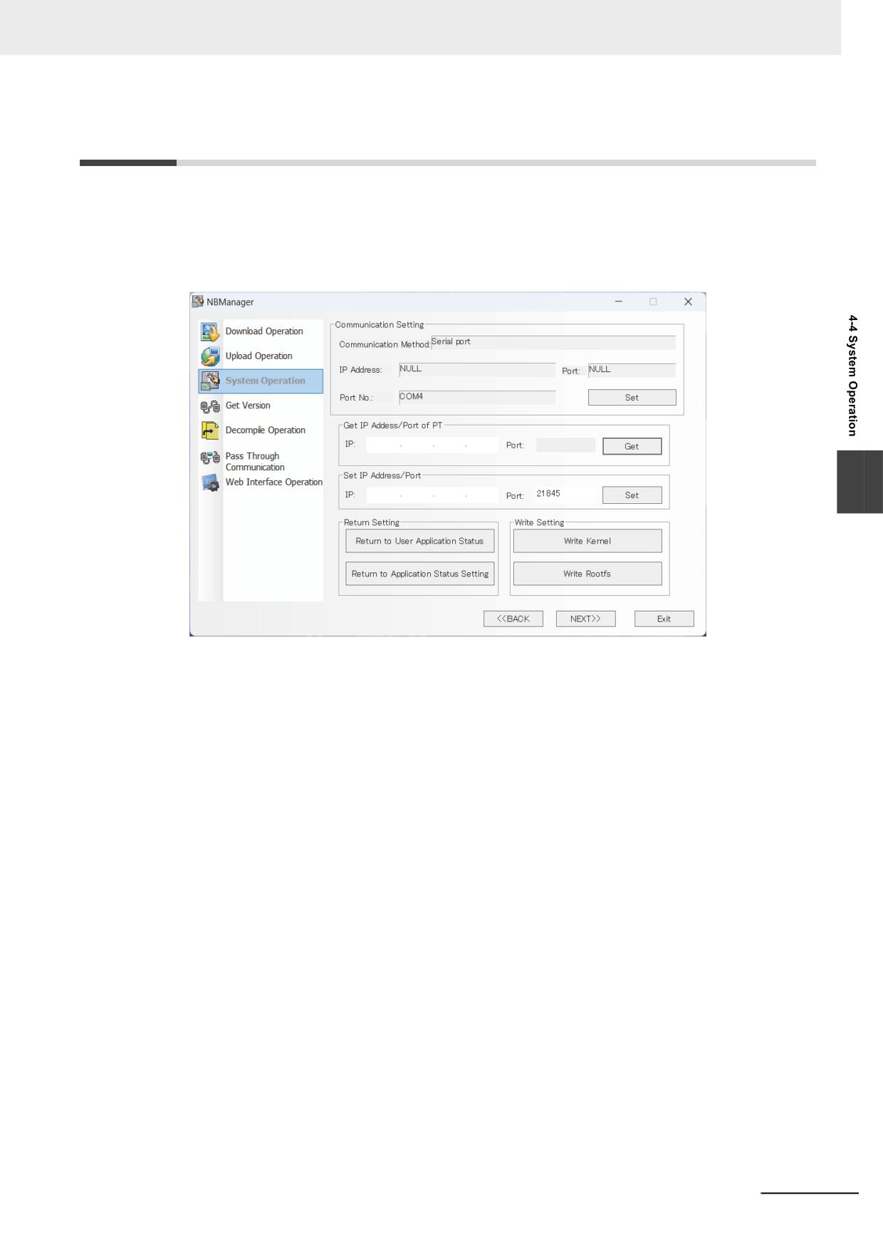
System Operation is mainly used for the firmware update on the NB unit.
The communication parameters must be set before the upload.
The Communication Setting is same as that of download.
4
NB-series Programmable Terminals NB-Designer Operation Manual(V106)
4-15
4 Functions of NBManager
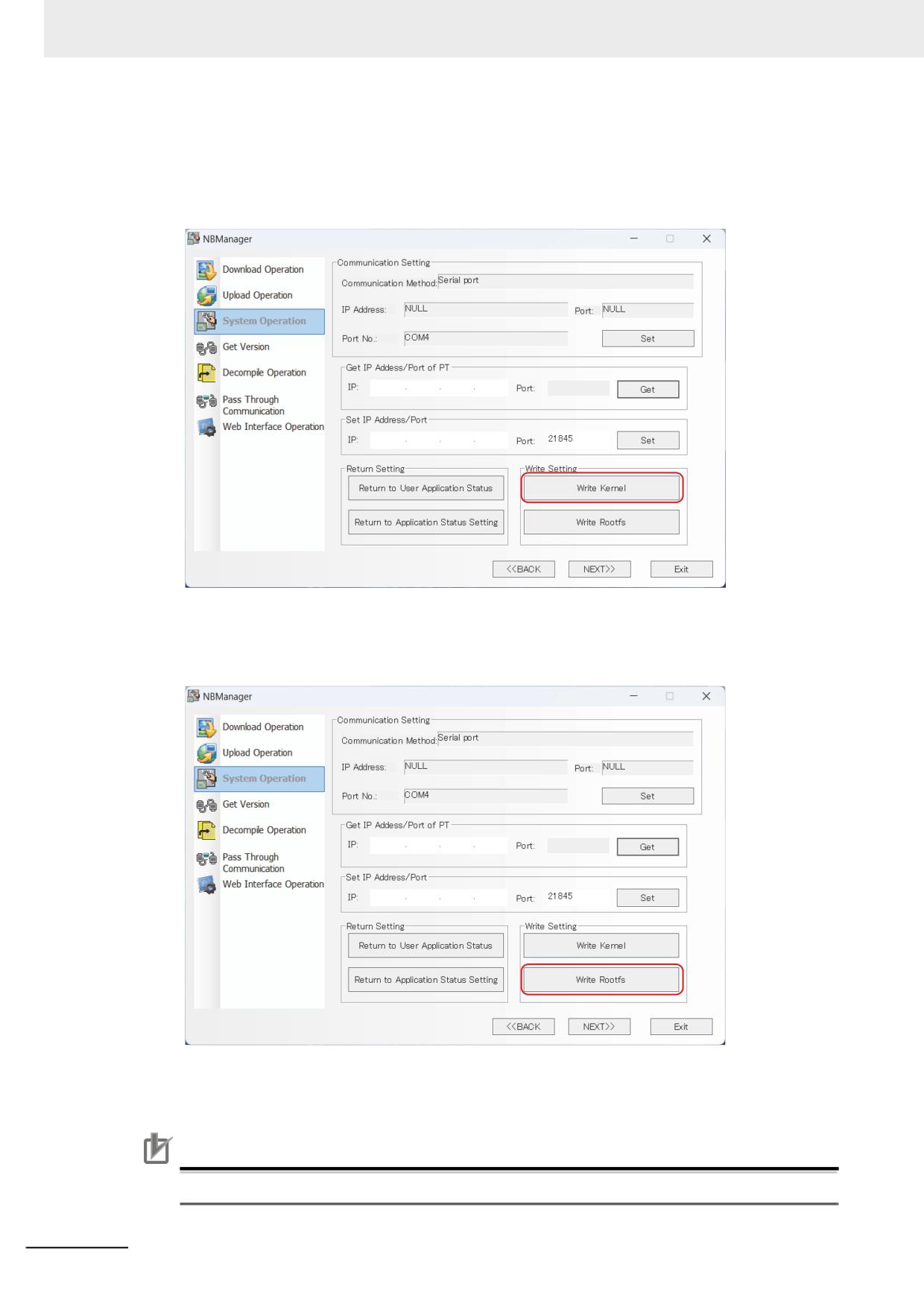
Firmware update
• Download Kernel
When executing system settings, set the DIP switch located at the back of the NB unit to System
Setting Mode (SW1: ON, SW2: OFF) before updating and restarting the NB unit.
Press the [Write Kernel] button to download the kernel to the NB unit.
After the download is successful, a dialog box pops up. Click the [OK] button to close the dialog box.
• Download Rootfs
Press the [Write Rootfs] button to download the rootfs to the NB unit.
After the download is successful, a dialog box pops up. Click the [OK] button to close the dialog box.
The firmware update is complete with the both download kernel and download rootfs operations.
Please turn off the power and return the DIP switch to User Project Mode (SW1: OFF, SW2: OFF).
Precautions for Correct Use
When performing a firmware update, be sure to write both the kernel and the rootfs.
4-16
NB-series Programmable Terminals NB-Designer Operation Manual(V106)
4 Functions of NBManager
4-5
Get Version
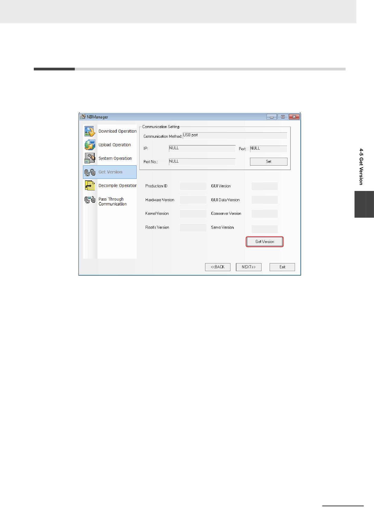
Get Version:
Clicking the [Get Version] can obtain the Production ID of NB Unit, Hardware Version, Kernel Ver-
sion, Rootfs Version, GUI Version, GUI Data Version, Comserver Version and Servo Version.
4
NB-series Programmable Terminals NB-Designer Operation Manual(V106)
4-17
4 Functions of NBManager
4-6
Decompile Operation
Decompile Operation:
Convert pkg/pkgx file to the format which can be handled with the NB-Designer.
Note When the multiple PTs are registered in a project, you need prepare pkg files for all the registered PTs in the
project. You must compile all the pkg files at the same time.
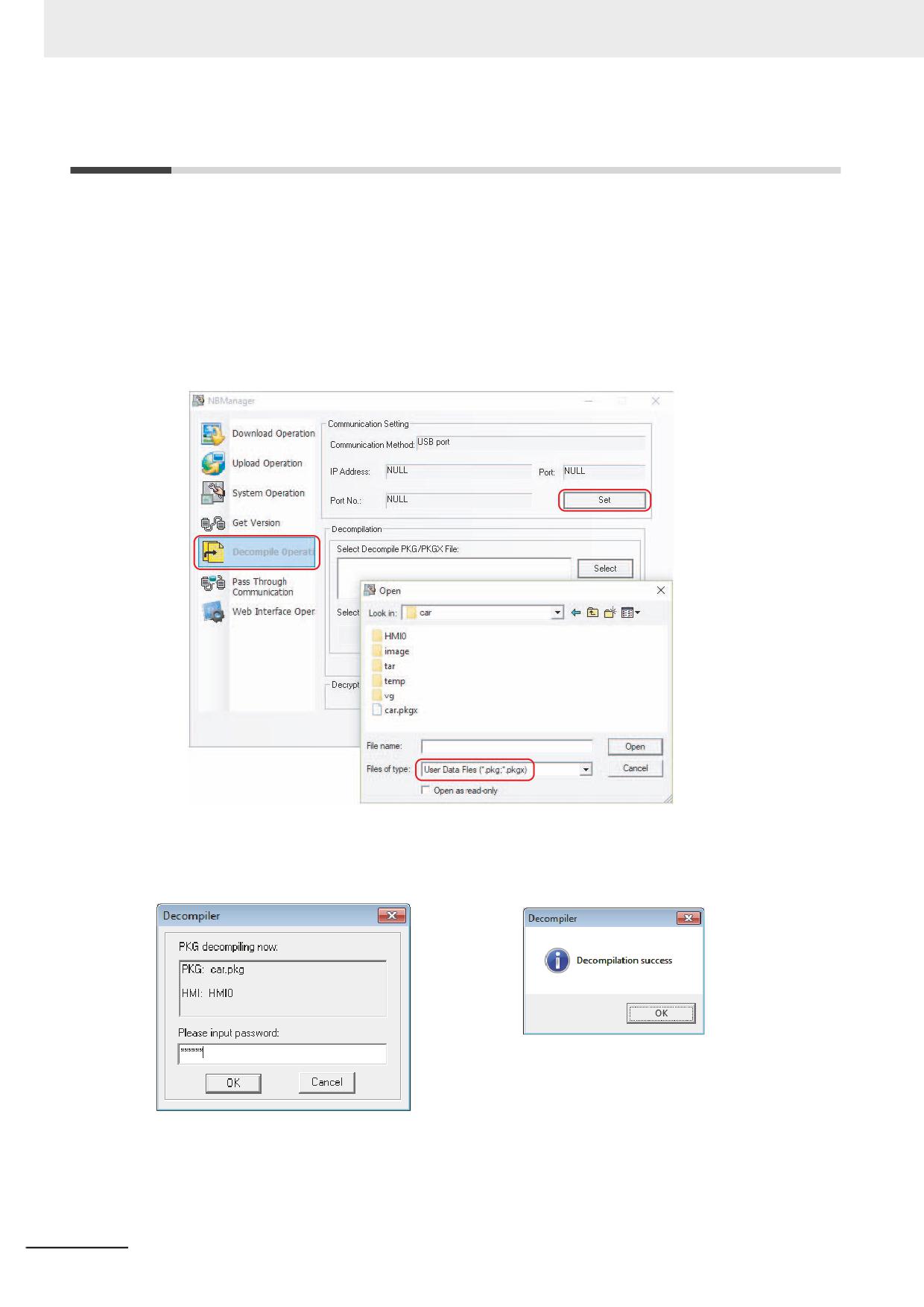
1 Select .pkg/pkgx files.
2 Set the folder of “Select Target Project Folder to Decompile”.
3 Click the [Decompile] button and input the decompile password, then click the OK button. When
the decomplie is completed, “Decompilation success!” dialog box will pop up.
The prerequisite for the decompile operation is “Allow Decompilation” is checked and the pass-
word is set in the [PT Extended Properties] tab during the project creation. The default decompi-
lation password is 888888.
4-18
NB-series Programmable Terminals NB-Designer Operation Manual(V106)
4 Functions of NBManager
4-7
Pass Through Communication
Pass Through Communication provided by NBManager allows the PLC programming software on PC
to connect the PLC directly via PT. In this case, PT functions just as the converter, so the user can
monitor or modify the PLC via PT, and the user can perform upload or download of PLC programs.
The only Communications available through the Pass Through Communications is the ones with Serial
port. The connection is as shown below.
Caution It does not support the Pass Through Communication through other PLC than that manufactured by
OMRON.
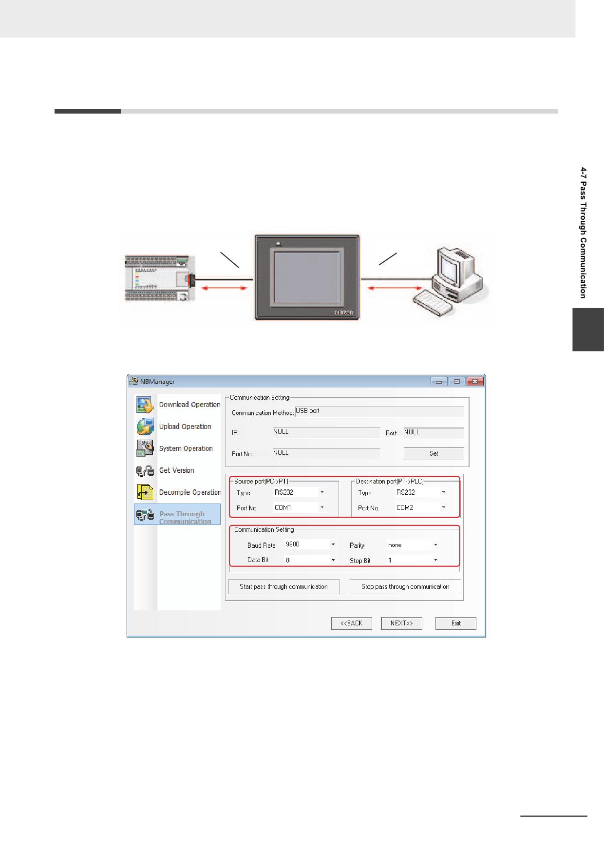
Destination port
Source port
COM
COM
COM
PLC
PC
4
Please set the Source port and Destination port of the Pass Through Communications. Source port
refers to the serial port of PT for connecting PC, while the Destination port refers to the serial port of PT
for connecting the PLC.
Take the communication between OMRON CP1H and NB5Q as example, and the operation
procedures are as follows:
1 Open the NBManager and select Pass Through Communication.
2 Specify the Communications path to control the Pass Through Communications with the Com-
munications settings. Select [USB port] in this case. The Serial port cannot be used to control
the Pass Through Communications. USB port is used to control the start and end of the pass
through communication.
3 Set the Source port and Destination port, as shown above.
NB-series Programmable Terminals NB-Designer Operation Manual(V106)
4-19
4 Functions of NBManager
4 The communication parameters are consistent with the settings of the Communications in
OMRON CP1H.
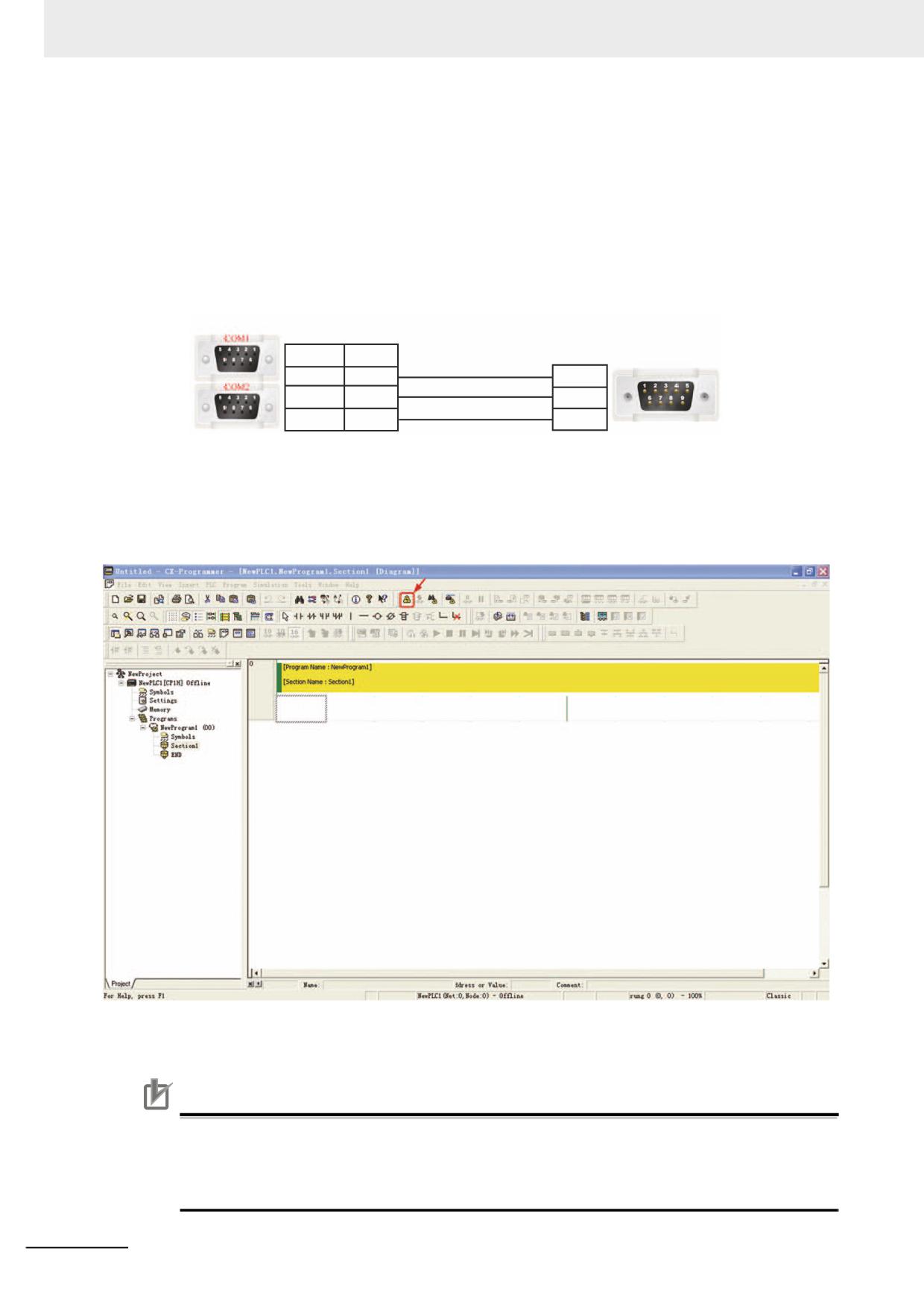
5 Connect the data transmission cable.
Connect the communication cable of OMRON CP1H to COM2 of PT, and connect the COM1of
PT and COM port of PC with the cable.
Note NB3Q-TWB(-V1) has only 1 COM port, so the pass through communication cannot be carried out.
Wiring of twisted cable:
PT connector
9pin D-SUB female
PC connector
COM 1
COM 2
9pin D-SUB (male)
3 RD
3 RD
3 TXD
2 SD
2 SD
2 RXD
9 SG
9 SG
5 GND
6 After “Start pass through communication” is clicked, PT will be in “Pass through mode”, and
“Pass through communication set successfully!” dialog box will pop up in NBManager.
7 Open CX-programmer for OMRON CP1H. Select “Online Operation”, then the PLC data can be
monitored or modified after the successful online.
8 Selecting “Stop pass through communication” will make “Pass through communication stopped
successfully!” dialog box pop up.
Precautions for Correct Use
• During the Communications with the Pass Through Communications, NB unit can be
accessed only within the system and the operations of the user project will be stopped.
• Besides the path of the Communications to communicate with PLC and others, the Communi-
cations path which controls the Pass Through Communications should be prepared.
4-20
NB-series Programmable Terminals NB-Designer Operation Manual(V106)
4 Functions of NBManager
4-8
Web Interface Operation
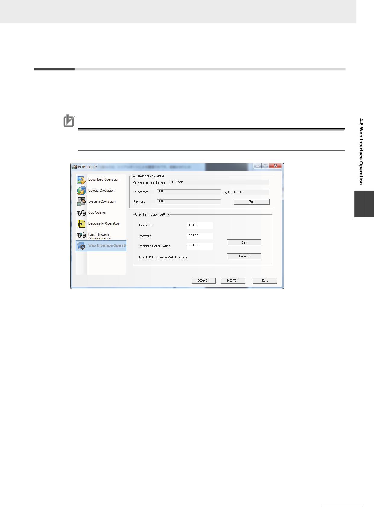
Set User Name and Password for using Web Interface. Refer to Web Interface (Page 8-1) for the
details of the Web interface.
Precautions for Correct Use
When you use Web interface, always modify User Name and Password into ones other than the
default settings in the respect of security.
4
1 Set User Name.
2 Set Password and Password Confirmation.
3 When you click [Set], User Name and Password will be transferred to the NB Unit.
Note 1
Available number of character available to set User Name and Password is 32 characters at max. Also the
available characters are restricted to single-byte alphanumeric and upper and lowercase are distin-
guished.
2
Clicking [Default] allows the User Name and Password to be returned to the default.
NB-series Programmable Terminals NB-Designer Operation Manual(V106)
4-21
4 Functions of NBManager
4-22
NB-series Programmable Terminals NB-Designer Operation Manual(V106)
5
Maintenance and Abnormality
Handling
This section describes the maintenance and check to prevent the abnormality
occurrence and the handling of the abnormalities occurred in NB Unit.
5-1
Maintenance
5-2
5
5-2
Checking and Cleaning
5-4
5-3
Abnormality Handling
5-6
5-4
Unit Replacement Precautions
5-10
NB-series Programmable Terminals NB-Designer Operation Manual(V106)
5-1
5 Maintenance and Abnormality Handling
5-1
Maintenance
Please perform the maintenance to ensure the NB Series always in the optimal status.
WARNING
Do not attempt to take the product apart and do not touch the product inside while the
power is being supplied. Otherwise it may result in electric shock.
Always ensure that the personnel in charge confirm that installation, inspection, and
maintenance were properly performed for the NB unit.
“Personnel in charge” refers to individuals qualified and responsible for ensuring
safety during machine design, installation, operation, maintenance, and disposal.
Ensure that installation and post-installation checks are performed by personnel in
charge who possess a thorough understanding of the machinery to be installed.
Do not use the input functions of the touch switch, etc. of the NB Unit, in applications
that involve human life, in applications that may result in serious injury, or for
emergency stop switches.
Do not attempt to disassemble, repair, or modify the NB Unit. Otherwise it may impair
the safety functions.
Never press at two or more points on the touch panel of the NB Unit at a time.
Otherwise, it may activate a switch somewhere between the two points.
5-2
NB-series Programmable Terminals NB-Designer Operation Manual(V106)
5 Maintenance and Abnormality Handling
Backup of application
When the unit needs to be repaired due to the occurrence of some faults or to be replaced by the
substitute, be sure to make backup of the applications and keep it in a safe location.
Spare part of Unit
It is recommended to prepare the spare part of NB Unit in advance in order to repair the system
when the faults occurred in NB Unit or the screen is not clear due to the backlight life expires.
Replace of battery
The lithium battery is used for the backup of the non-screen data such as calendar data, clock data
etc.
The life of the battery is approximate 5 years at 25 °C (1 year = 365 days ×12 hours /day). If the
battery is used at high temperature, its life will be reduced. According to the ambient environment,
after taking back-up of the data, request for the repair.
5
NB-series Programmable Terminals NB-Designer Operation Manual(V106)
5-3
5 Maintenance and Abnormality Handling
5-2
Checking and Cleaning
Please clean and check the NB Series periodically to ensure the NB Series always in the optimal
status.
Cleaning method
If the display part is dirty, then the screen will hard to see. Please perform cleaning periodically
according to the following points:
• During the daily cleaning, please use the dry soft cloth. But if use the dry soft cloth to clean
forcefully when it is too dirty, the front panel may be damaged. In this case, use the wet cloth to
clean it in advance.
• When the dirt cannot be cleaned by dry cleaning, please dip the cloth into the diluted neutral
washing agents (concentration of 2%) completely first, and then perform cleaning after the wet
cloth is wringed out.
• Waste, ethylene products or tape sticking to the Unit for a long period will generate dirt. If there is
dirt sticking to the Unit, please remove it during the cleaning.
Precautions for Safe Use
Do not use benzene, paint thinner, or other volatile solvents, and do not use chemically treated
cloths.
Checking method
Please perform checking once every 6 months to 1 year. But the frequent checking should be
necessary when the Unit is used in the extreme environments such as the environment with high
temperature, high humidity or more dust etc.
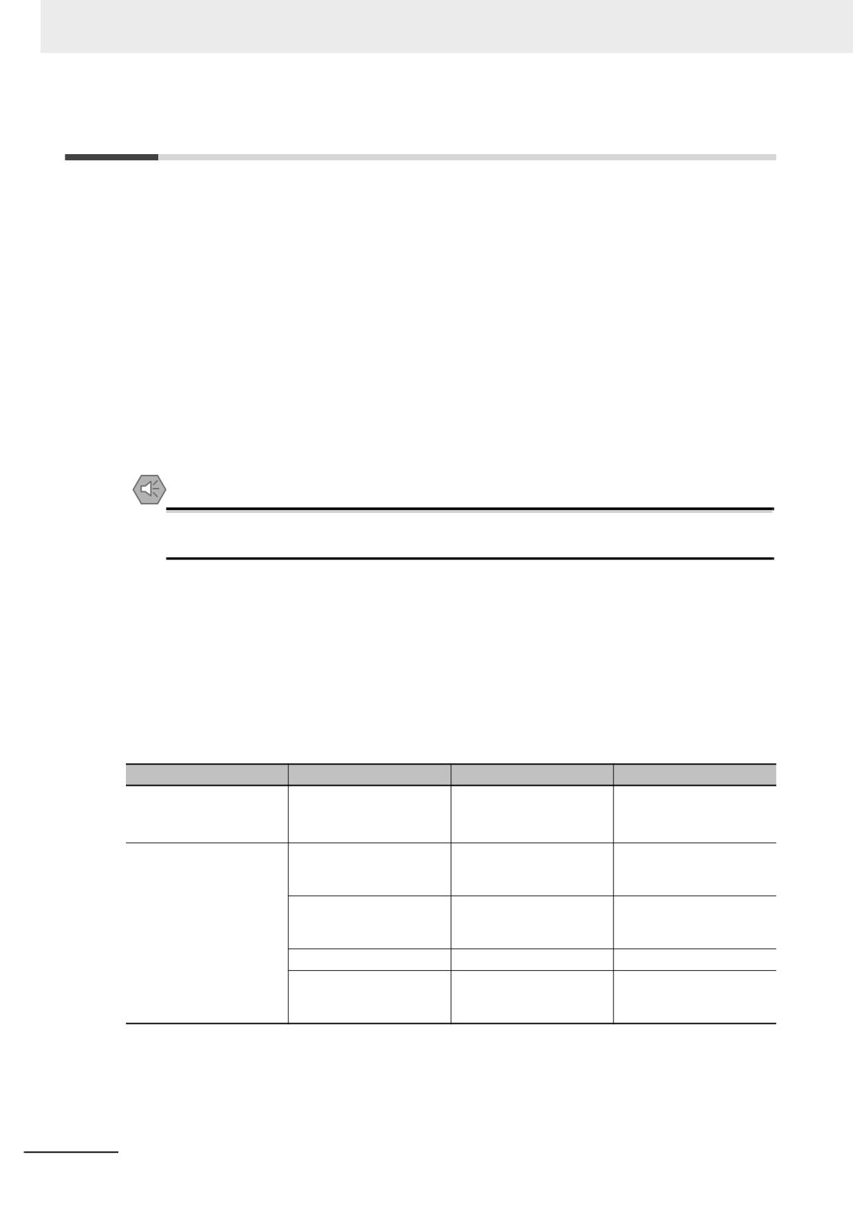
Checking items
Please check the following items for the criterion. If the item doesn’t conform to the criterion, please
improve the surrounding environment, retighten the screw etc. to make it conform to the criterion.
Checking Items
Checking Contents
Criterion
Checking Method
Supply voltage
Voltage fluctuation at
Allowable voltage
Multimeter
power terminal
fluctuation range
(DC24V, -15% to +15%)
Surrounding environment
Ambient temperature
0°~50°C
Thermometer
state
(temperature inside
operation panel)
Ambient humidity
10%~90% RH(without
Hygrometer
(humidity inside operation
condensation)
panel)
Dirt
Without dirt
Visual check
Oil mist sticking
No oil penetrating into the
Visual check
space between the front
panel and Unit box
5-4
NB-series Programmable Terminals NB-Designer Operation Manual(V106)
5 Maintenance and Abnormality Handling
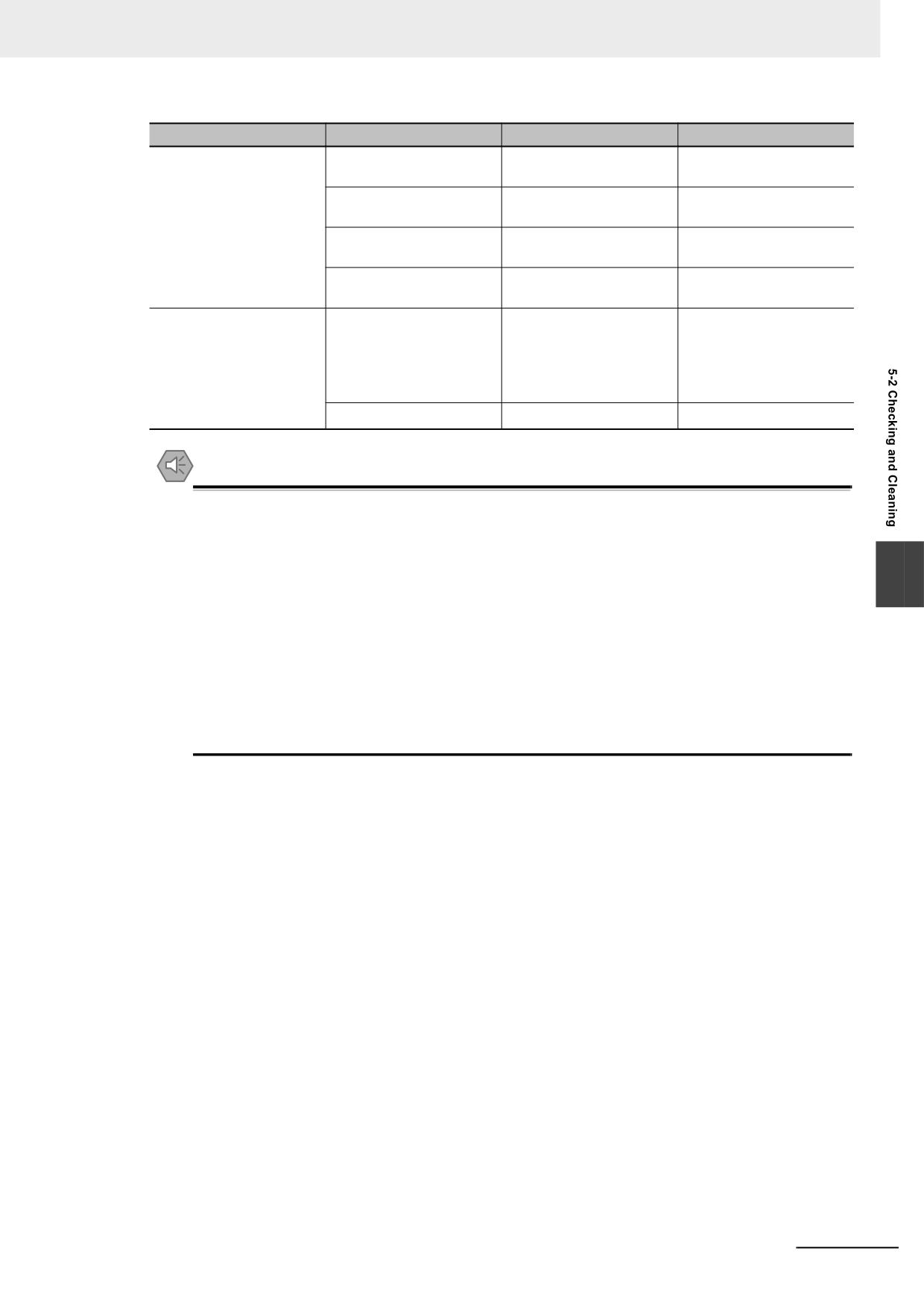
Checking Items
Checking Contents
Criterion
Checking Method
Installation state
Looseness of fixing metal
Specified torque
Phillips screwdrivers
pieces etc.
Connection state of
Inserted fully and without
Phillips screwdrivers
connector for the cable
looseness.
Looseness of screw for
Without looseness
Phillips screwdrivers
external wiring
State of external
Without abnormality such
Visual check + multimeter
connection cable
as disconnection etc.
Object with expected life
Backlight brightness
With enough brightness
Visual check
Backlight life: approx.
50,000 hours (Typ) at
room temperature (25 °C)
with 40% brightness.
Battery
5 years (at 25 °C)
NB local time
Precautions for Safe Use
• The back light or rubber packing of NB unit cannot be replaced.
• Deterioration over time can cause the tough points to move. If the Calibrate the touch panel
periodically.
• Water resistance will be lost if the front sheet is torn or is peeling off. Do not use the Unit, if the
5
front sheet is torn or is peeling off.
• Dispose of the Units and batteries according to local ordinances as they apply.
• Periodically check the installation conditions in applications where the PT is subject to contact
with oil or water.
• The rubber packing will deteriorate, shrink, or harden depending on the operating environ-
ment. Inspect the rubber packing periodically.
• In order to replace the battery, the NB units are also necessary to be replaced. Although it is
restricted to NB10W-01B, the battery replacement is available to be dealt as a repair.
NB-series Programmable Terminals NB-Designer Operation Manual(V106)
5-5

5 Maintenance and Abnormality Handling
5-3
Abnormality Handling
This section describes the handling methods for the abnormalities.
During abnormality occurrence
When the abnormality occurred during the operation of PT unit, the following information will prompt.
WARNING
Do not attempt to disassemble, repair, or modify the NB Unit. Otherwise it may impair
the safety functions.
Precautions for Safe Use
Confirm the safety of the system before turning ON or OFF the power supply, or pressing the
reset button.
Information
Descriptions
PLC No Response: cc-pp-d
PLC No Response: the 3 group of numbers following PLC No Response represent
the PT No., PLC Station No. and Serial Port No. respectively.
PLC Response Error
PLC Response Error: PLC responses one piece of unexpected information which
may caused by the read or write command. Please check if the device functions
well, or verify the Tag Variable settings.
Macro Code Error: xxxx
Programming problems, endless loop or execution timeout exist in Macro. Please
(Macro No.)
check the Marco. The number in the later position is the Macro No.
System error
It is system error which means the error occurs inside the PT.
5-6
NB-series Programmable Terminals NB-Designer Operation Manual(V106)
5 Maintenance and Abnormality Handling
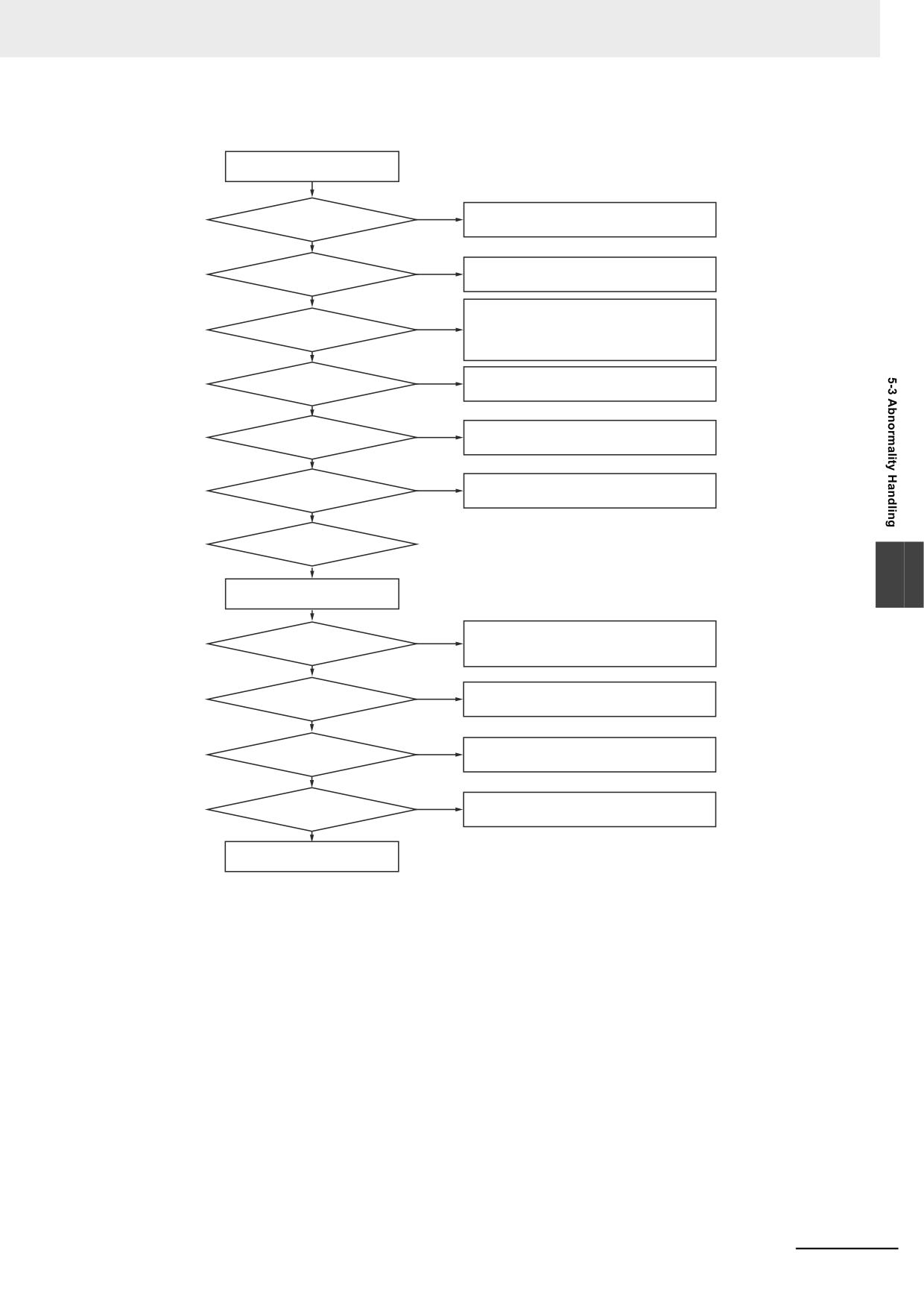
Solutions for “PLC No Response” and “PLC Response Error”
PLC No Response
Yes
Check whether the type and settings
NO
Check if the PLC Type used currently and the
of the PLC are correct or not.
one for the PLC on the project are correct.
Yes
Check whether the cable is
NO
Refer to [Appendix-4 Fabrication of the Connec-
wired correctly or not.
tion Cable] in NB series Setup Manual.
Yes
Check whether the baud rate, parity bit, data bit,
stop bit are correct or not, the communication type
NO
Check whether the communi-
is RS232 or RS485?
cation setting is correct or not.
Refer to [Appendix-4 Fabrication of the Connection
Cable] in NB series Setup Manual.
Yes
Check whether PLC station
NO
Refer to [Appendix-4 Fabrication of the Connec-
no. is correct or not.
tion Cable] in NB series Setup Manual.
Yes
Check whether the PLC area
NO
Check the content of the variable table.
and range are correct or not.
Yes
NO
Check whether the PLC address
Refer to the relevant PLC document.
supports the write operation.
Yes
Please contact with
OMRON service center.
5
PLC Response Error
Yes
Check if the Tag Variable settings are the same
Check whether the tag variable
NO
as those on the PLC, and if they are different,
settings are correct or not.
re-import the Tag Variable settings from the PLC.
Yes
Check whether the type and settings
NO
Check if the PLC Type used currently and the
of the PLC are correct or not.
one for the PLC on the project are correct.
Yes
Check whether the PLC area
NO
Check the content of the Variable Table.
and range are correct or not.
Yes
Check whether the PLC address
NO
Refer to the relevant PLC document.
supports the write operation.
Check the arrangement of 9-pin
RS-232C female socket port.
When compile error occurs
In the Output Window, you can see the error number and error reason such as:
Address error for Parts or over-limit.
Using too many screens and components may cause a compile error. The number of screens
should be approximately 2,000 or less, and the number of components should be 15,000 or less in
the entire project.
Operations related to files cannot be executed via networks.
Do not use the system locale-dependent characters for the project file name, graphics library file
name, and folder name.
NB-series Programmable Terminals NB-Designer Operation Manual(V106)
5-7
5 Maintenance and Abnormality Handling
When operations become slow or when a periodical process cannot be
executed as specified
Check the available memory space on the LW9136 system memory, and secure the adequate
memory. (LW9136 shows a reference value for available memory space.)
The periodically executed processes such as alarm detection, data logging, timer, or macro may
have a longer execution interval than specified or not be executed, depending on the loads caused
by screen display or communication, or the overlapping processes. Check the actual operation to
adjust the load of the process.
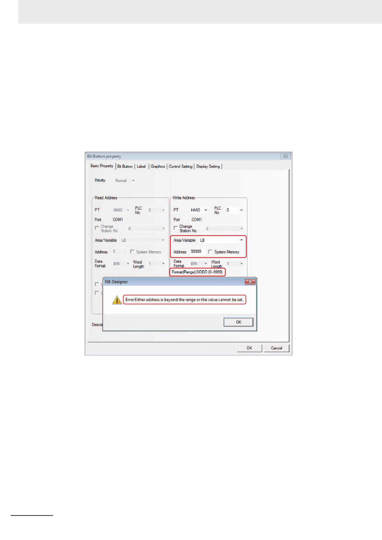
For some cases, NB-Designer will provide the information similar to “Either address is beyond the
range or the value cannot be set.” as shown below during the designing period.
For the settings of PLC address, refer to 3-5-4 Read/Write Address for PLC (Page 3-59) and for
information of PLC address, refer to PLC manual.
5-8
NB-series Programmable Terminals NB-Designer Operation Manual(V106)
5 Maintenance and Abnormality Handling
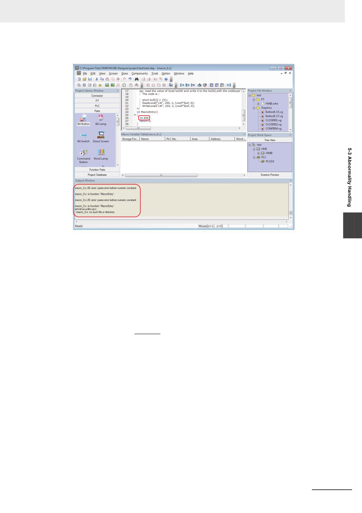
Grammatical errors as C language are checked during compilation in Macro and if any problem
occurs, it will be displayed.
5
For the Macro, refer to 3-9 Macro Function (Page 3-265).
Some parts on the screen are not updated
Communications traffic is too much to update all the data. Reduce the number of the parts to update
to the level of proper data traffic.
Data transmission component cannot transfer all the data
Traffic is too high to transfer all the data. Alter the time-out setting with LW9536/9537. For the time-
out setting, refer to the expression below:
X
Time-out Period
(T) = (
+1) × N sec.
M × 16
X: Total amount of transferred data (unit: word/bit)
M:The number that is defined as the maximum size of word/bit block package in the communication
settings of NB-Designer.
N:The value that is set in LW9536 (write) or LW9537 (read).
Data upload is failed
Uploading the data that created with NB-Designer version 1.34 or earlier using NB-Designer version
1.35 or later may fail. If you fail in data upload, try again with NB-Designer version 1.34 or earlier.
NB-series Programmable Terminals NB-Designer Operation Manual(V106)
5-9
5 Maintenance and Abnormality Handling
5-4
Unit Replacement Precautions
When the Unit should be replaced for the defectiveness found during the checking, please pay
attentions to the following points:
• Perform backup of the screen data of NB Unit in advance.
• The screen data may be deleted when the Unit is repaired by OMORN.
• Be sure to turn OFF the power supply before the replacement.
• After the replacement, please confirm whether the abnormality still exists or not.
• When the defect device is returned for repair, please attach the paper with the detailed description of
the problem to the Unit, and contact the supplier printed on the back cover.
5-10
NB-series Programmable Terminals NB-Designer Operation Manual(V106)
6
Functions Related to External
Memory
This section describes the functions related to external memory.
6-1
Components Related to External Memory
6-2
6-1-1
Function Key
6-2
6-1-2
Event, Event History Display and Event Display
6-5
6-1-3
Data History, Data Log and XY Graph
6-7
6-1-4
Operation Log
6-8
6-1-5
Recipe Data
6-11
6
6-1-6
CSV Import / Export
6-12
6-1-7
PLC Control
6-13
6-1-8
File List
6-14
6-1-9
FTP Server
6-15
NB-series Programmable Terminals NB-Designer Operation Manual(V106)
6-1
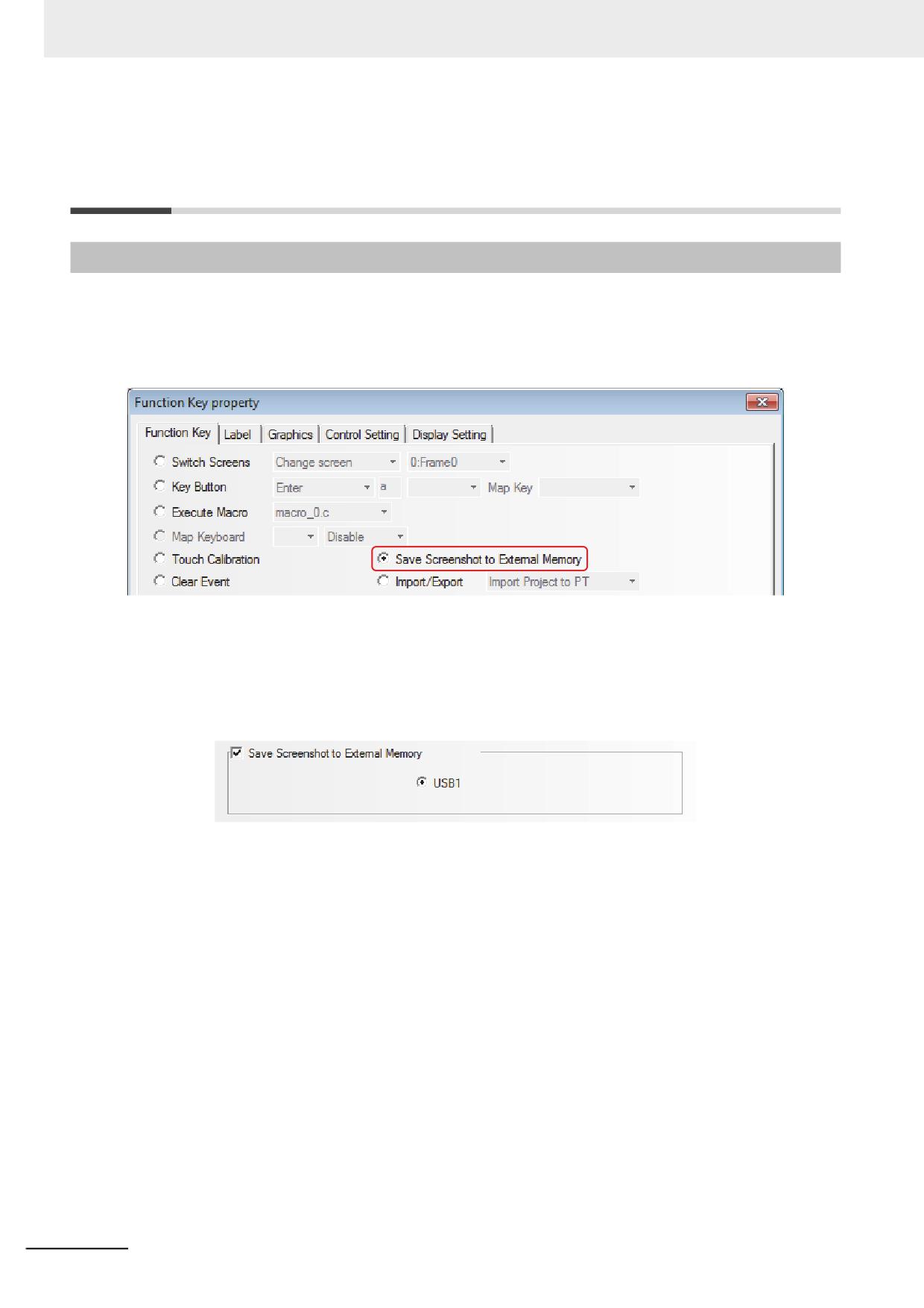
6 Functions Related to External Memory
6-1
Components Related to External
Memory
6-1-1
Function Key
Save Screenshot to external memory
When the component is touched, the content of the current screen will be stored into the external
memory in the form of “bmp picture”. Using the this function allows the PT screen stored as the
graphics.
Note 1
“Save Screenshot to Extended Memory” is only applicable to the PT with USB HOST.
2
Function of “Save Screenshot to Extended Memory” supports the offline test, indirect online test and direct
online test. All the screenshot pictures got by this test method are stored in the “\disk\usb1\scr” file under
the installation folder of NB-Designer software.
To save the screenshot to the external memory, it needs to make settings in the [PT] tab in [PT
Property] dialog box.
The “.rmp” pictures stored in the external memory is named in storage time form (i.e. “yyyy-mm-dd,
hh:mm:ss:ms) by default, such as “2010-09-01, 10:12:50:203.bmp”. But the picture name can be
customized by the user through the system memory LW9470 to control the prefix text string of the
graphics file. For example: if the text contents of 16 words from LW9470 to LW9485 are “Version No. -
No.20100001-”, then the “bmp” file will be stored with the name of “Version No. -No.20100001-2010-09-
01, 10:15:28:421.bmp”.
Note After the “Save Screenshot to Extended Memory” operation is performed for about 1 minute, the external
memory can be removed to ensure the successful storage of the screenshot.
6-2
NB-series Programmable Terminals NB-Designer Operation Manual(V106)
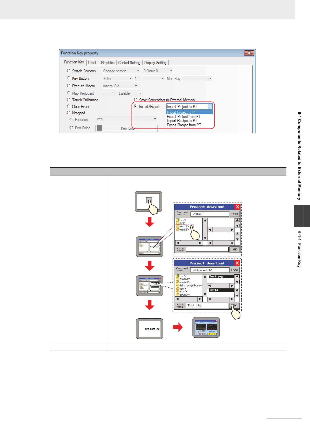
6 Functions Related to External Memory
Import/Export Function
When this function is selected, touching the Function Key can realize the import or export of project
data and recipe data. This function needs to be used in combination with File List component and it is
only applicable to the PT with USB Host.
Descriptions of Import/Export Function
Import Project To PT
Imports the project (.pkg/pkgx) from the external memory into the PT. After the
project is imported, the system will restart and the imported project will be operated.
6
Pop up Frame 5
PKG/PKGX LOAD OK
Export Project From PT
Exports the project (.pkg/pkgx) from the PT into the external memory.
NB-series Programmable Terminals NB-Designer Operation Manual(V106)
6-3
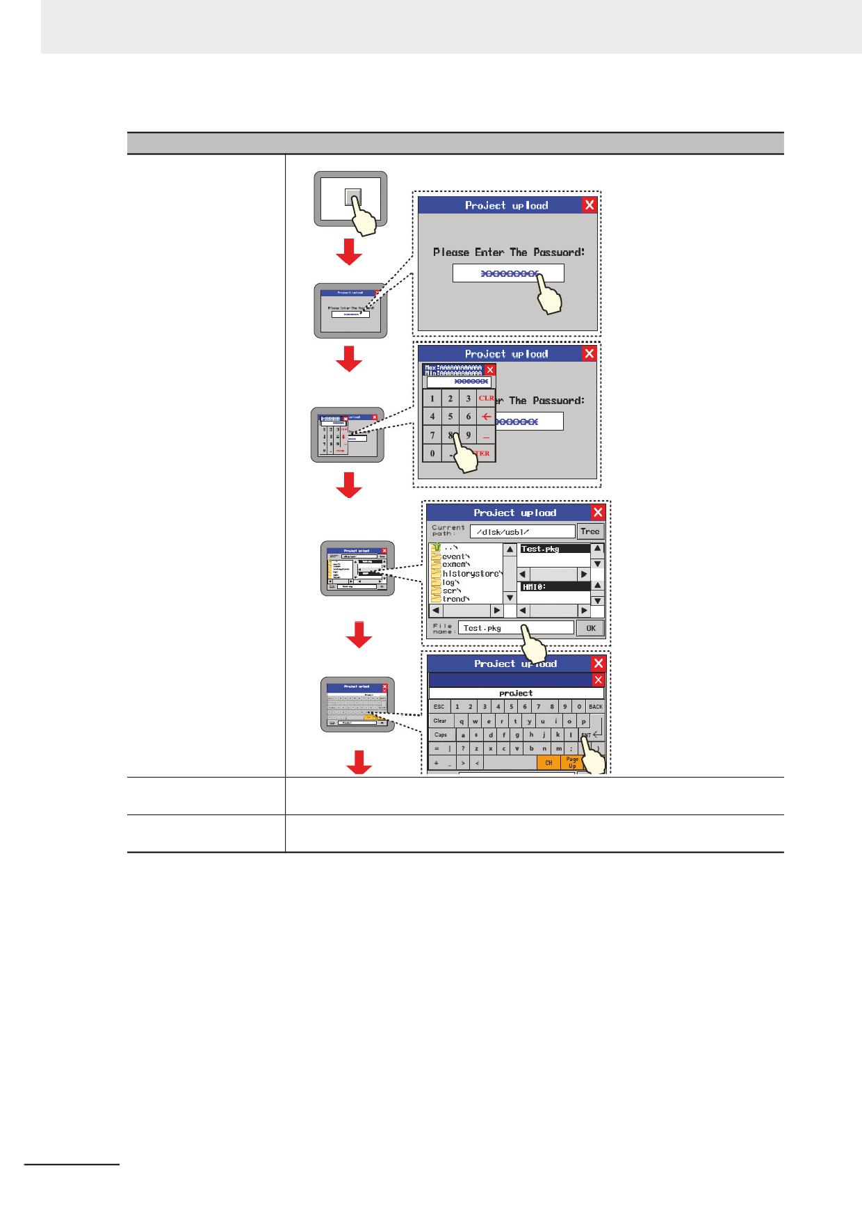
6 Functions Related to External Memory
Descriptions of Import/Export Function
Pop up Frame 6
Input upload
password
Pop up Frame 5 and
select save path
Input file name
Import Recipe To PT
Imports the recipe file (.rcp) from the external memory into the PT. For the operation
procedures, refer to [Import Project To PT].
Export Recipe From PT
Exports the recipe file (.rcp) from the PT into the external memory. For the operation
procedures, refer to [Export Project From PT].
6-4
NB-series Programmable Terminals NB-Designer Operation Manual(V106)
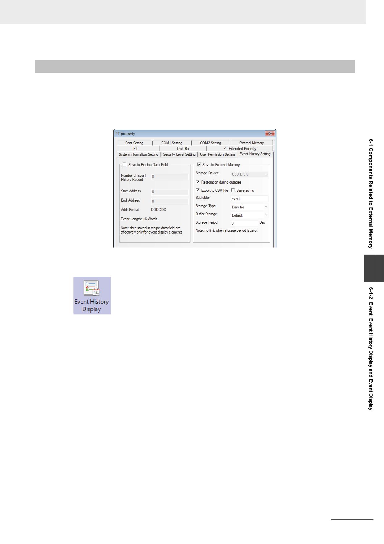
6 Functions Related to External Memory
6-1-2
Event, Event History Display and Event Display
Saving Event, Event History Display and Event Display into the external
memory:
The Event, Event History Display and Event Display can be stored in the external memory by check-
ing the [Save to External Memory] option in the [Event History Setting] tab in the [PT Property] dia-
log box, as shown below:
Event History Display
6
The Event History Display component is used to search and display the event history
information, which is logged in “Event Setting” database and whose state meets the current
triggering conditions, in the table form.
Note 1
The [Read Address] for the Event History Display is the memory address used for searching the histor-
ical event records. The default Word Length is 2.
2
The Event History Display component only supports the PT with USB HOST.
3
If the Event History Display component is to be used, it needs to check the [Save to External Memory]
option in the [Event History Setting] tab in the [PT Property] dialog box and set the path for storing the
historical event information files.
NB-series Programmable Terminals NB-Designer Operation Manual(V106)
6-5
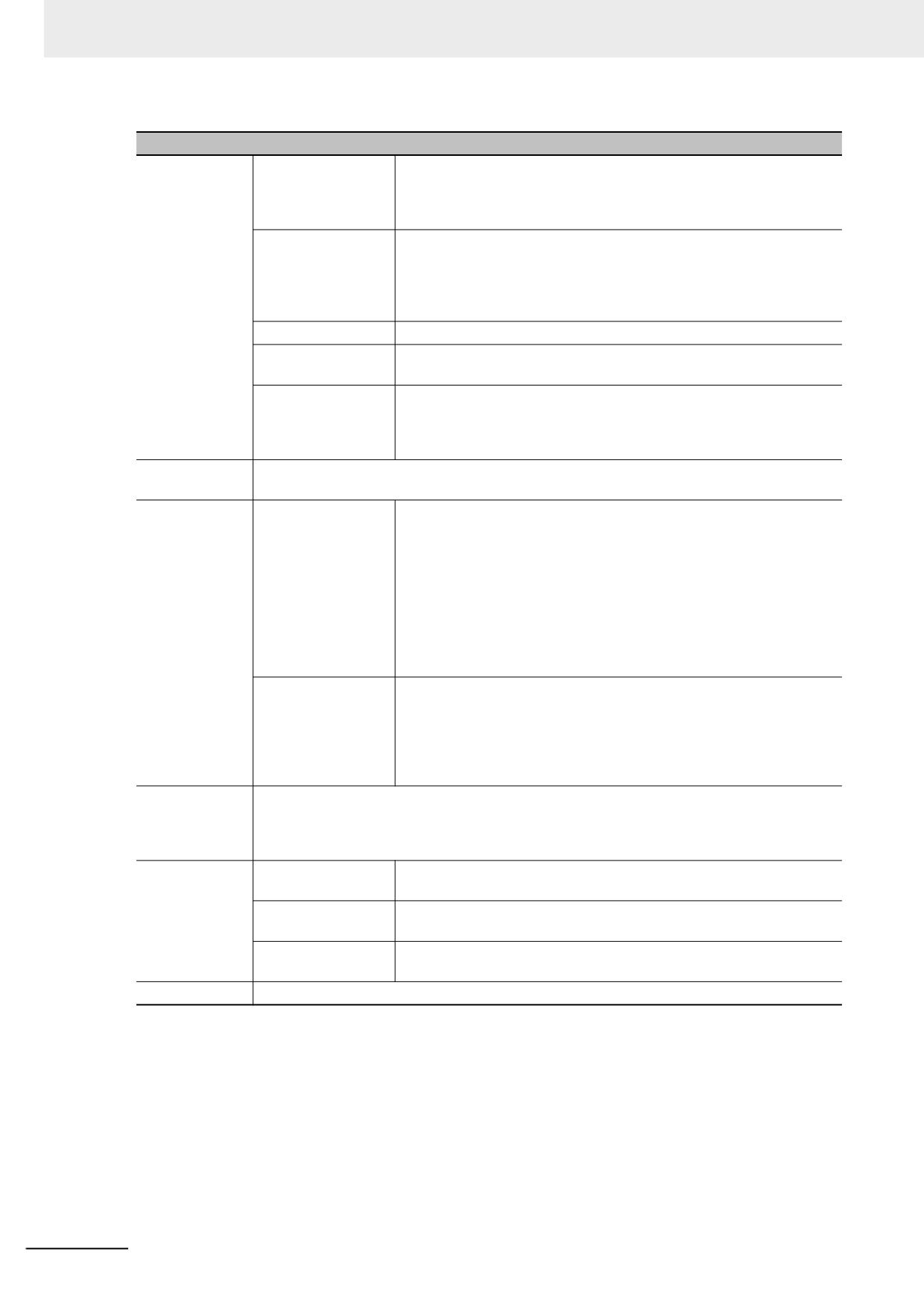
6 Functions Related to External Memory
Descriptions of Table Display Properties
Display Item
Time
Checking it means the event occurred time, checked time and
canceled time will be displayed and the time format can be selected
There are 3 formats available, and HH, MM, SS and MS refer to the
hour, minute, second and millisecond respectively.
Date
Checking it means the event occurred date, checked date and
canceled date will be displayed and the date format can be selected
among three formats such as DD*MM*YY, MM*DD*YY, and
YY*MM*DD, and YY, MM and DD refer to the year, month and date
respectively.
Date Separator
Three characters of delimiter(/,-,.) are available. i.e. 11/06/24.
Sequence Number
Checking it the sequence number of each event information will be
displayed.
Ascending
When it is checked, the event information will be displayed in the
ascending order, i.e. the latest event will be displayed on the bottom.
When it is not checked, the event information will be displayed in the
descending order, i.e. the latest event will be displayed on the top.
Background
Sets the Background Color, Title Bar Background Color, Frame Color and Frame Width for the
Color
Event History Display component table.
Event History
Query by File Name
When it is checked, the value of specified memory being 0 means to
Query
call out today’s or the latest event history information, and the value of
specified memory being 1 means to call out the event history
information stored on the previous day and so on. [For example] With
two event history information files 20110621.csv and 20110624.csv
stored in the external memory, when the value of specified memory is
0, the event history information stored on June 24th, 2011 can be
called out, while the event history information stored on June 21th,
2011 can be called out and displayed when the value of specified
memory is 1.
Query by Date
When it is checked, the date will be input into the specified memory
and the event history information corresponding to the date will be
called out. The date format is yyyymmdd (Where, yyyy, mm and dd
refer to the year, month and date respectively.) [For example] Inputting
20110624 into the specified memory can call out and display the event
history information saved on June 24th, 2011.
Border Setting
Border Color, Style and Width for each row or each column and the Row Spacing and Column
Spacing with the unit of pixel point. Checking “Horizontal Line” means the separator will be
displayed horizontally, and checking “Vertical Line” means the separator will be displayed
vertically.
Status display
Occurring
Display the information indicates that the event is occurring in the
status column. Although it is set to “0” by default, it can be modified.
Checked
Display the information indicates that the event is checked in the status
column. Although it is set to “1” by default, it can be modified.
Canceled
Display the information indicates that the event is canceled in the
status column. Although it is set to “2” by default, it can be modified.
Title Bar Setting
Sets the Name and Font displayed in Title Bar of the table.
6-6
NB-series Programmable Terminals NB-Designer Operation Manual(V106)
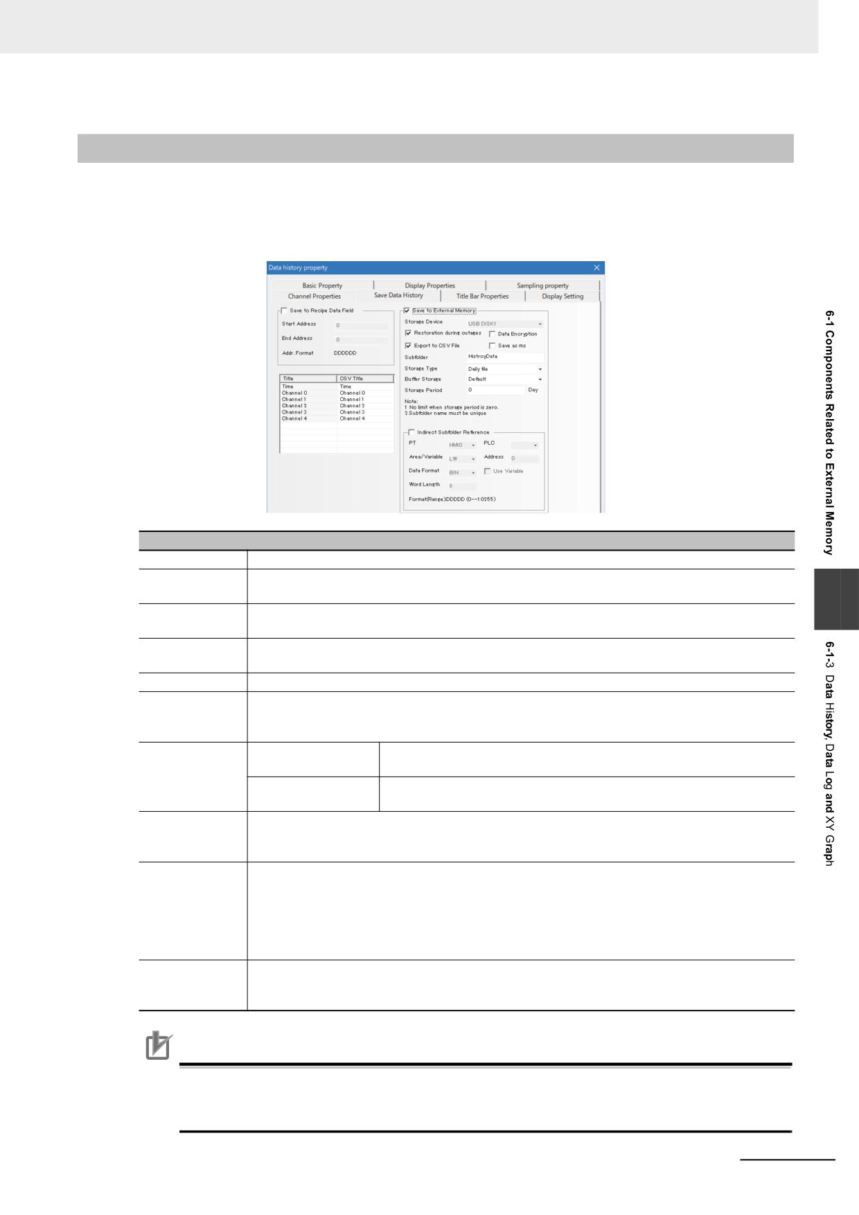
6 Functions Related to External Memory
6-1-3
Data History, Data Log and XY Graph
Saving the related information into the external memory:
When the sampling data is being saved into the external memory, if you want to remove the external
memory from the PT, the special system memory LB9154 (USB1) must be turned OFF before
removal. If the external memory is removed without the procedure, the data will be corrupted lost.
Descriptions of Save Historical Data
Storage Device
USB 1
Restoration
When the NB units restarts because of the power interruption, checking in this option allows
during outages
resetting the event information to the previous status of the power interruption.
6
Export to CSV
Export the data information in CSV format to the external memory. The path for storing this
File
CSV file is “/trend/subfolder name/file name”.
CSV Title
When exporting the data to a csv file, you can give titles by each channel. If you change the
number of channels, titles become default ones.
Save as ms
Makes the data sampling time accurate to the millisecond and records it into the CSV file.
Subfolder
Sets the subfolder name of CSV file saved to the external memory. The users can change the
default subfolder name of Data History component by themselves to “History Data”, that of
Data Log component to “History Trend” and that of XY Graph to “XY_CHART”.
Storage Type
Daily File
Stores the sampling data by day and records them into the CSV file
named in “yyyy mmdd” form.
Single File
Stores the sampling data by the number of records and records them
into the CSV file with the name of “Subfolder Name”.
Buffer Storage
Provides a kind of buffer storage mechanism. When the data written into the external memory
amounts to the set size of the buffers, the writing is only performed once. “Default” means no
buffering, i.e. the writing operation will immediately be performed once the data is generated.
Storage Period
Sets the upper limit for the storage amount of data history with the unit of “Day” for Daily File and “Record”
for Single File. When the [Daily File] is selected, the file will be named in “yyyy mmdd” form and the Storage
Period is the upper limits of the number of CSV files in this path; if the Storage Period is exceeded, the
oldest file will be deleted. If the [Single File] is selected, the file will be named in “Subfolder Name” form, the
Storage Period is the upper limit of the records archived in the file; if the archived records are reached to
the Storage Period, the storage will not be continued. (yyyymmdd refers to the execution date.)
Indirect
Sets the name of subfolder read from the specified memory with the word length up to 16.
Subfolder
Reference
Precautions for Correct Use
When saved to a CSV file, a title may differ depending on the version of NB-Designer for compi-
lation. NB-Designer with version 1.49 and earlier does not have the function to change a title and
the title is output in the default text to a CSV file.
NB-series Programmable Terminals NB-Designer Operation Manual(V106)
6-7
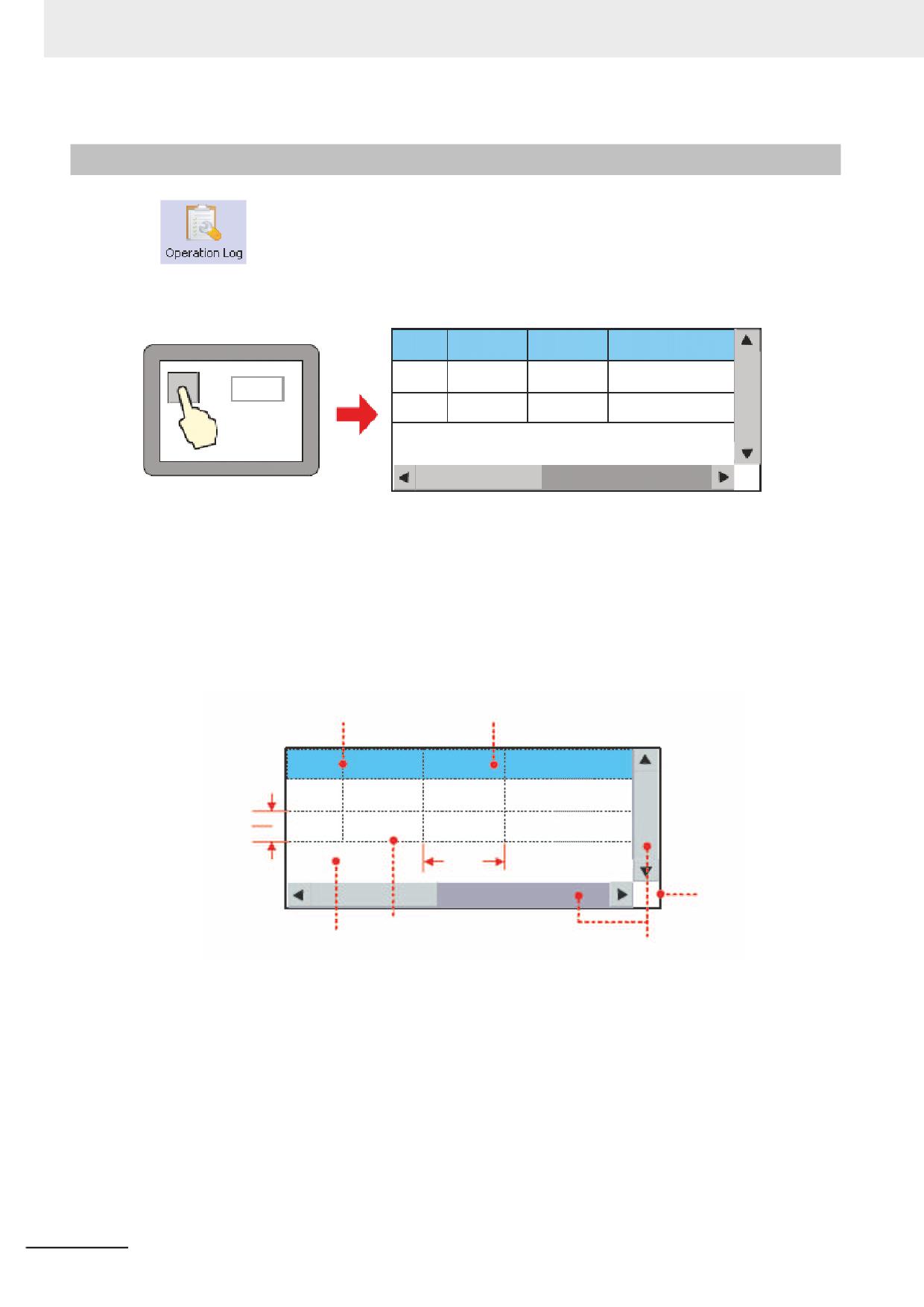
6 Functions Related to External Memory
6-1-4
Operation Log
The Operation Log component can be used to record or display the operations made
by the users to the PT in the table form. The operation log will be stored into the external memory in
CSV format.
No.
Date
Time
Log
0
11/06/24
11:23:20
Parameter Corr
123
1
11/06/24
11:22:45
Start Running
Note 1
The [Read Address] for the Operation Log component is the memory address used for searching the
operation logs. The default Word Length is 2.
2
The Operation Log component can display the operated results of Bit Button, Number Input and Text
Input components etc.
3
The Operation Log component is only applicable to the PT with USB HOST.
Descriptions of Table Properties:
Vertical Line
Title Bar
No.
Date
Time
Log
0
11/06/24
11:23:20
Parameter Corr
Row Spacing
1
11/06/24
11:22:45
Start Running
Column
Space
Frame
Horizontal Line
Background
System Scroll Bar*
Note When the information in vertical and/or horizontal direction contained in the Operation Log component can
not be displayed completely, the system will automatically display the scroll bar for the user to conveniently
view the operational records by scrolling up and down.
The System Scroll Bar Width can be set to the value ranging from 20 to 120 (pixel) in the [PT
Extended Properties] tab in [PT Property] dialog box.
6-8
NB-series Programmable Terminals NB-Designer Operation Manual(V106)
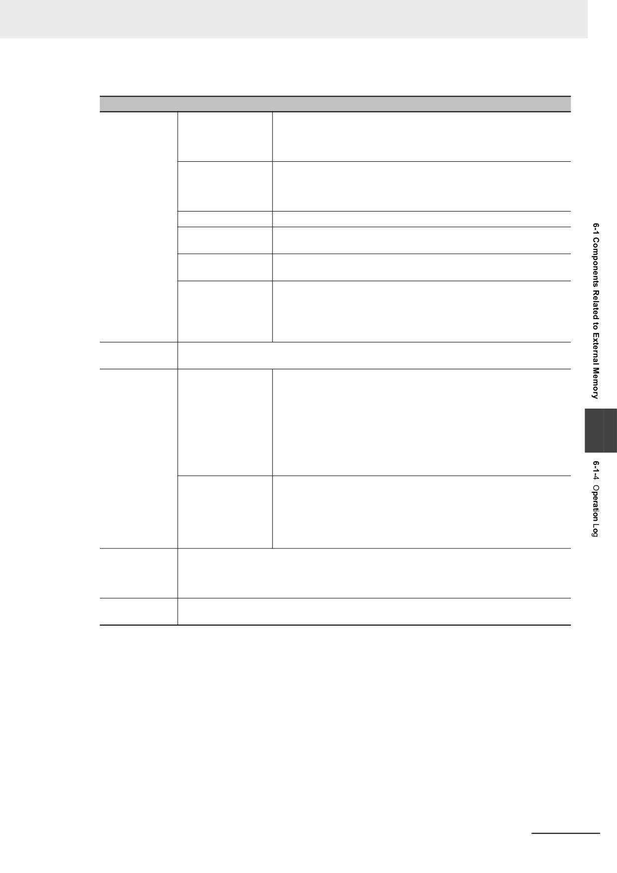
6 Functions Related to External Memory
Descriptions of Table Display Properties
Display Item
Time
Checking it means the operation time will be displayed and the time
format can be selected. There are 3 time formats available (such as
HH:MM:SS, HH:MM, and HH:MM:SS:MS), and HH, MM, SS and MS
refer to the hour, minute, second and millisecond respectively.
Date
Checking it means the operation date will be displayed and the date
format can be selected. There are 3 time formats available (such as
DD*MM*YY, MM*DD*YY, YY*MM*DD), and YY, MM and DD refer to
the year, month and date respectively.
Date Separator
Three characters of delimiter(/,-,.) are available. i.e. 11/06/24.
Sequence Number
Checking it means the sequence number of each operation record will
be displayed.
User Name
Checking it means to the information on the user performing the
current operation will be displayed.
Ascending
When it is checked, the operation logs will be displayed in the
ascending order, i.e. the latest operation log will be displayed on the
bottom. When it is not checked, the operation logs will be displayed in
the descending order, i.e. the latest operation log will be displayed on
the top.
Background
Sets the Background Color, Title Bar Background Color, Frame Color and Frame Width for the
Color
Operation Log table.
Operation Log
Query by File Name
When it is checked, the value of specified memory being 0 means to
Query
call out today’s or the latest operational records, and the value of
specified memory being 1 means to call out the operational records
made on the previous day and so on. [For example] With two operation
log files 20110621.csv and 20110624.csv stored in the external
6
memory, when the value of specified memory is 0, the operation logs
saved on June 24th, 2011 can be called out, while the operational
records saved on June 21th, 2011 can be called out and displayed
when the value of specified memory is 1.
Query by Date
When it is checked, the date will be input into the specified memory
and the operation logs corresponding to this date will be called out.
The date format is yyyymmdd, where yyyy, mm and dd refer to year,
month and date respectively. [For example] Inputting 20110624 into
the specified memory can call out and display the operation logs saved
on June 24th, 2011.
Border Setting
Sets the Border Color, Style and Width for each row or each column and the Row Spacing and
Column Spacing with the unit of pixel. Checking “Horizontal Line” means the separator will be
displayed horizontally, and checking “Vertical Line” means the separator will be displayed
vertically.
Title Bar
Sets the Name and Font displayed in the Title Bar of the table. Note: The vector font cannot be
specified in the log contents.
Note When the User Permission function is used, the name of user performing the current operation will be
displayed on the User Name column.
NB-series Programmable Terminals NB-Designer Operation Manual(V106)
6-9
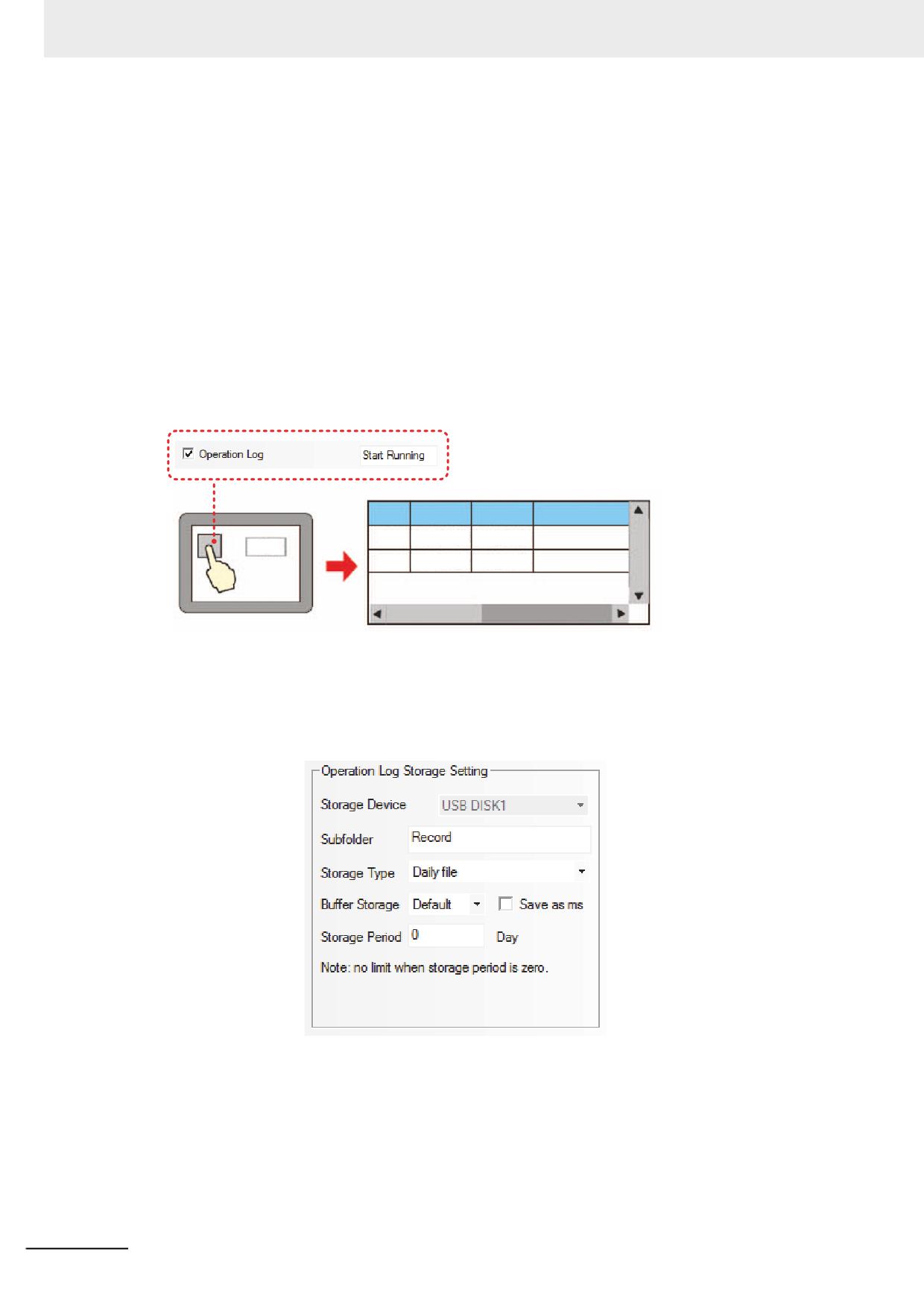
6 Functions Related to External Memory
• Settings for related Properties of Operation Log component
Storage of Operation Log
When the Operation Log component is used, the path for storing the log file should be set in the
[Operation Log Storage Setting] option in the [PT Extended Properties] tab in the [PT Property] dia-
log box.
For the output file in CSV format, if the [Daily File] is selected, the file storage path is “log/subfolder
name/yyyymmdd.csv”, and if the [Single File] is selected, the storage path is “log/subfolder
name/subfolder name.csv”. (Where, yyyymmdd is the created date of the operational records. For
example: 20110101)
Settings of the components for Operation Log
For the component with the requirement of displaying the Operation Log in the Operation Log, it
needs to check the [Operation Log] option in the [Security Setting] part in the [Control Setting] tab in
the property dialog box of the component on which should be operated.
No.
Date
Time
Log
0
11/06/24
11:23:20
Parameter Corr
123
1
11/06/24
11:22:45
Start Running
Saving the related information into the external memory:
The related information can be stored in the external memory by using the “Operation Log Storage
Setting” option in the [PT Extended Properties] tab in the [PT Property] dialog box, as shown below.
6-10
NB-series Programmable Terminals NB-Designer Operation Manual(V106)
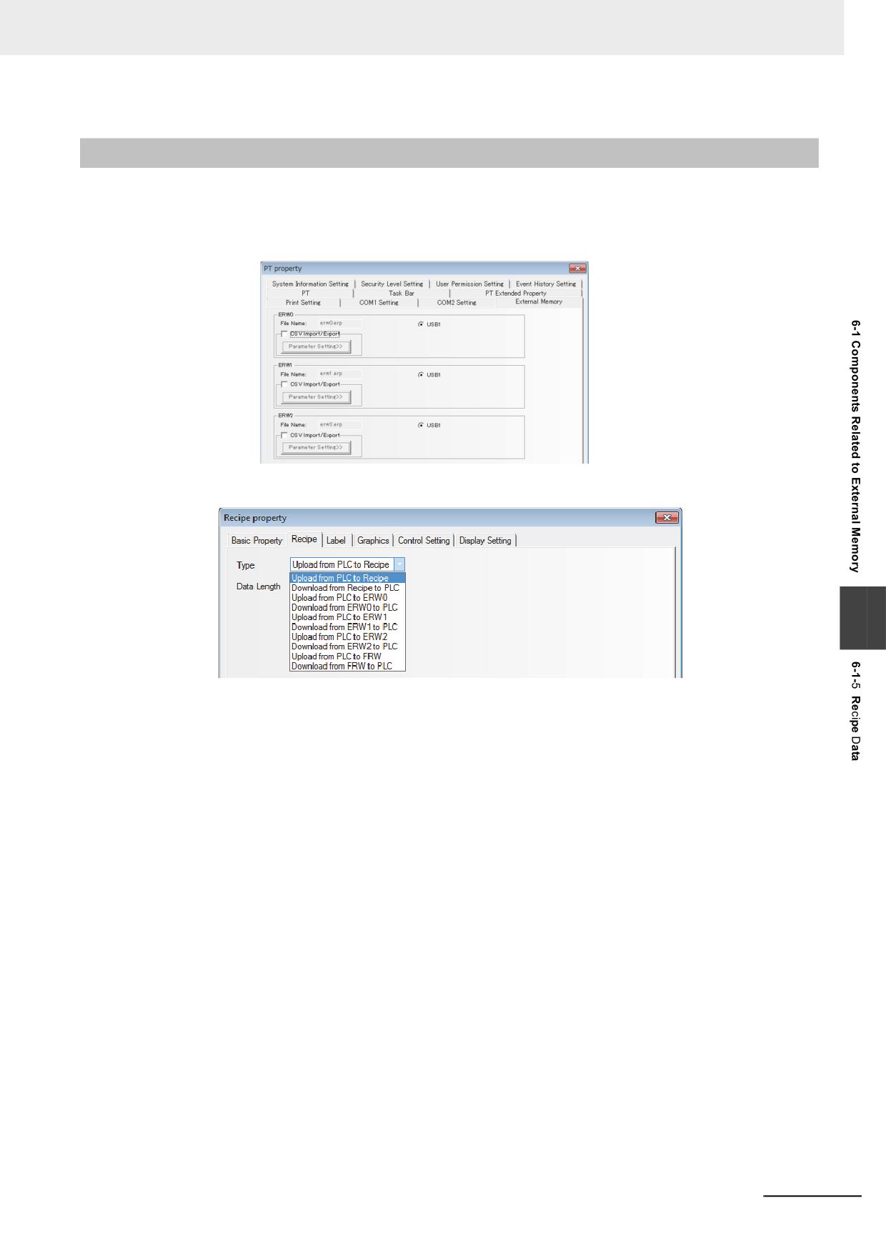
6 Functions Related to External Memory
6-1-5
Recipe Data
Saving the related information into the external memory:
Select the external memory in the [External Memory] tab in the [PT Property] dialog box, as shown
below.
Later, make settings in the [Recipe] tab in the [Recipe Property] dialog box.
6
The following functions can be realized:
Upload from PLC to ERW0: Transfers the data in memory specified by PLC or controller to the ERW0
memory of the external memory.
Download from ERW0 to PLC:Transfers the data in ERW0 memory of the external memory to the
memory specified by PLC or controller.
Upload from PLC to ERW1: Transfers the data in memory specified by PLC or controller to the ERW1
memory of the external memory.
Download from ERW1 to PLC:Transfers the data in ERW1 memory of the external memory to the
memory specified by PLC or controller.
Upload from PLC to ERW2: Transfers the data in memory specified by PLC or controller to the ERW2
memory of the external memory.
Download from ERW2 to PLC:Transfers the data in ERW2 memory of the external memory to the
memory specified by PLC or controller.
NB-series Programmable Terminals NB-Designer Operation Manual(V106)
6-11
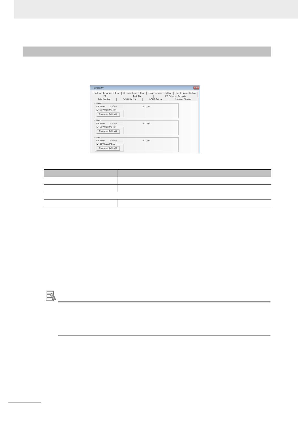
6 Functions Related to External Memory
6-1-6
CSV Import / Export
By converting data of the CSV file stored in the external memory into ERP file, the data can be handled
as ERW memory when the [CSV Import / Export] check box is checked in external memory setting.
The file names to be converted are as follows:
Names of CSV files
Address range *
ERWx_0.csv
ERWx
0
-
4194303
ERWx_1.csv
ERWx
4194304
-
8388607
:
ERWx_511.csv
ERWx
2143289344
-
2147483647
* The size of ERW memory per CSV file is 4194304 WORD.
(x=0, 1, 2)
CSV files are stored in "/exmem/[Subfolder]/ERWx_y.csv" (x=0, 1, 2, y=0 to 511). For [Subfolder]
setting, refer to 3-10-9 External Memory (Page 3-324).
• CSV file format
The CSV file format is as follows:
• Numbers, “-” (minus) , and “.” (decimal point) are supported
• Write one data for one line
• Use “LF” or “CRLF” code at the end of the line.
Additional Information
For parameter setting, refer to 3-10-9 External Memory (Page 3-324).
Specify a value using the data type that you set in [Memory Type].
If [Memory Type] is a floating-point value, exponential expressions are not supported, and non-
numeric characters like NaN are handled as error.
6-12
NB-series Programmable Terminals NB-Designer Operation Manual(V106)
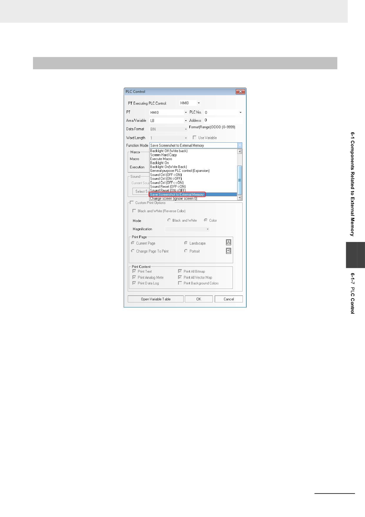
6 Functions Related to External Memory
6-1-7
PLC Control
Save Screenshot to External Memory
6
For more details of “Save Screenshot to External Memory”, refer to 6-1-1 Function Key (Page 6-2).
NB-series Programmable Terminals NB-Designer Operation Manual(V106)
6-13
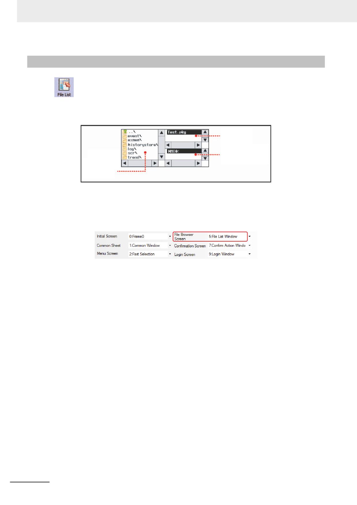
6 Functions Related to External Memory
6-1-8
File List
The File List is used to display the file information of the external memory. This component is
divided into three parts: the left part displays the information on the folder under the current folder, the
upper-right part displays the information on the file under the current folder, and the lower-right part
displays the PT information on the selected project file (.pkg/pkgx) or the recipe file (.rcp).
Information on the file
under the current
directory
HMI information on the
Information on
selected file under the
the folder under
current directory
the current
directory
The File List component, a kind of special component, needs to be used in combination with
[Import/Export] function of Function Key.
[Frame5:File List Window] is generated automatically when the new project is created, convenient for
the users to call it during the import or export of project file or recipe file. The specified pop-up File
Browser Screen can be set in the [PT Extended Properties] tab in the [PT Property] dialog box.
6-14
NB-series Programmable Terminals NB-Designer Operation Manual(V106)
6 Functions Related to External Memory
6-1-9
FTP Server
Upon request from the PC, FTP server transfers files in the external memory, which is inserted to the
NB Unit, to the PC connected through Ethernet. This function only supports the models with Ethernet
port and USB HOST. For settings, refer to 3-10-1 PT (Page 3-291).
To use FTP server function, make the connection from the PC with the following settings.
Server: IP Address of the NB Unit
User name: root
Password: The value set in PT property setting
Port: 21
Additional Information
• This function can be enabled or disabled by changing the value of LB9296 on the NB Unit.
• By enabling FTP server, the NB Unit will be exposed to risk of attacks from external networks.
Before enabling FTP server, you need to take security measures to prevent attacks from exter-
nal networks and to minimize the possible damage.
• NB's FTP server function supports functions defined by RFC959. It does not ensure connec-
tions with all the FTP clients due to unsupported extended commands or options. Test connec-
tions with an actual device before use.
6
NB-series Programmable Terminals NB-Designer Operation Manual(V106)
6-15
7
PictBridge Printing
This section describes the PictBridge printing function.
7-1
PictBridge Function
7-2
7-2
Setting Method for Using Printing Function
7-4
7-3
Components Related to Printing and Setup Descriptions
7-6
7-3-1
PLC Control
7-6
7-4
List of System memories Related to Printing
7-8
7-5
List of Error Codes for Printing
7-9
7-6
Recommended Printer Models
7-10
7
NB-series Programmable Terminals NB-Designer Operation Manual(V106)
7-1
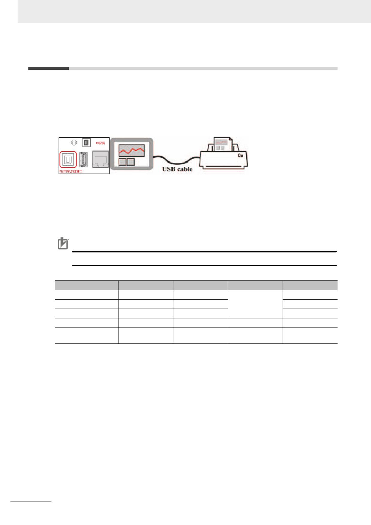
7 PictBridge Printing
7-1
PictBridge Function
PictBridge is the industry standard for direct printing with the device and a printer directly connected.
This standard enables digital images from the device to be printed directly by a printer, eliminating the
need of connecting the device to a PC, thus greatly facilitating the printing process in various
conditions.
The NB series touch panel supports the PictBridge protocol, and connected to such a printer with the
USB Slave port, it can perform printing of images and other data.
In order to use the PictBridge function, it is necessary to update the Kernel and Rootfs in NB-Designer
Ver. 1.2.2 or later. For the update method, refer to 4-4 System Operation (Page 4-15) in NB-Designer
Operation Manual.
When downloading project from NB-Designer or transferring project from the USB to the NB Unit, if the
message of “Please update the Kernel and Rootfs in the NBManager.” is displayed, it means user
should update the NB Kernel and root file system.
Precautions for Correct Use
NB-TWB-V1 do not support the PictBridge function.
Version information list
NB-Designer
Kernel
Rootfs
Is necessary to update?
Enable Print
Ver. 1.10
1317
1337
Necessary
-
Ver. 1.20
1317
1389
-
Ver. 1.21
1317
1389
Checked by default
Ver. 1.22
1458
1517
Unnecessary
Checked by default
Determined by the
Unchecked by
Ver. 1.23 or later
1458
1548
user project *
default
* If the printing function is not required, the user should uncheck the “Enable Printing” before opening
the previous project with the NB-Designer version 1.23. Then recompile and download the project.
7-2
NB-series Programmable Terminals NB-Designer Operation Manual(V106)
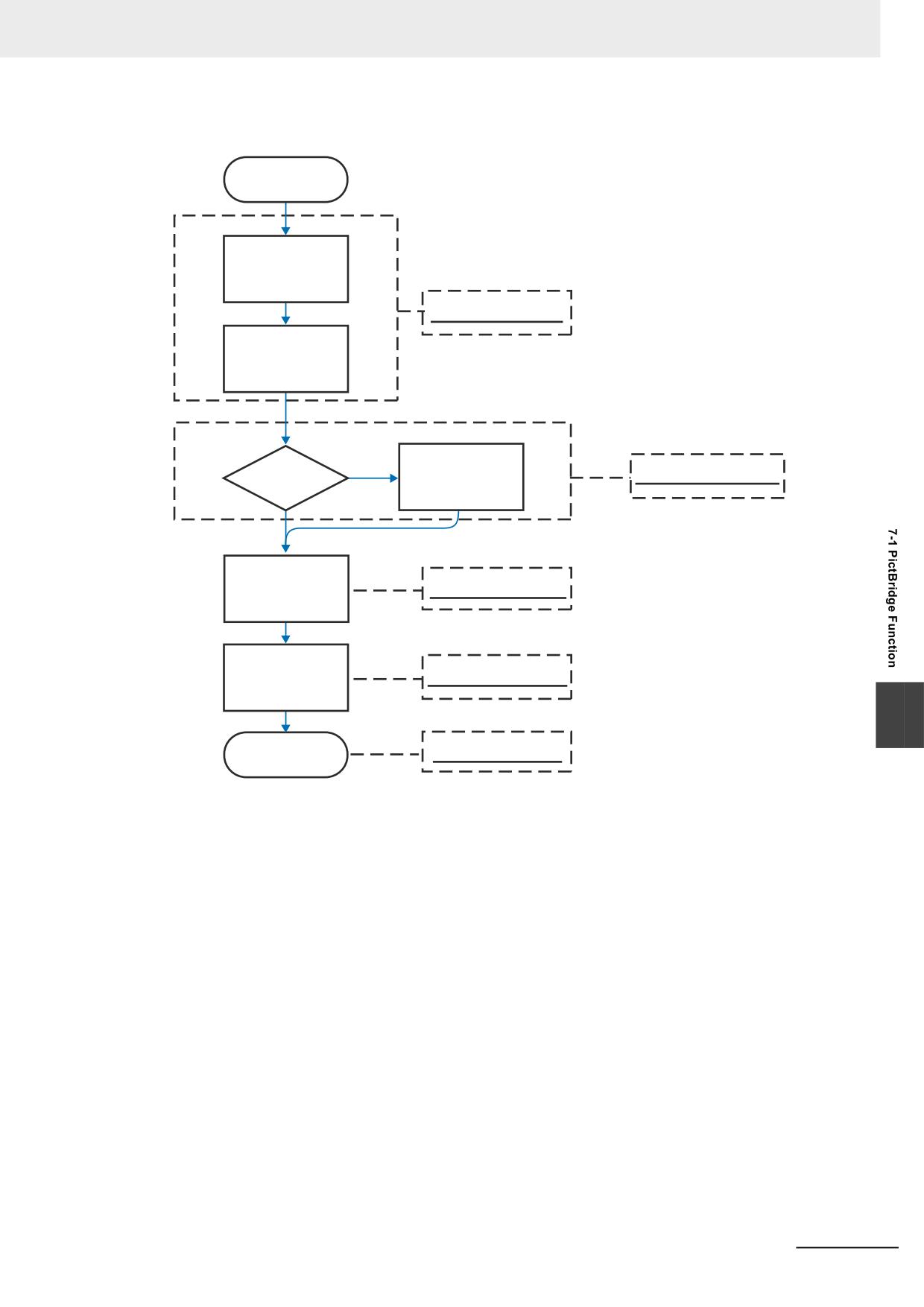
7 PictBridge Printing
The printing function updates flow chart
Start
Update Kernel
Downloader Mode
Update Rootfs
Disable Printer
Is print function
System Setting Mode
disabled?
N
Function
Y
Download
User Project Mode
Project
Enable Printer
System Setting Mode
Function
7
Printer is
User Project Mode
Available
NB-series Programmable Terminals NB-Designer Operation Manual(V106)
7-3
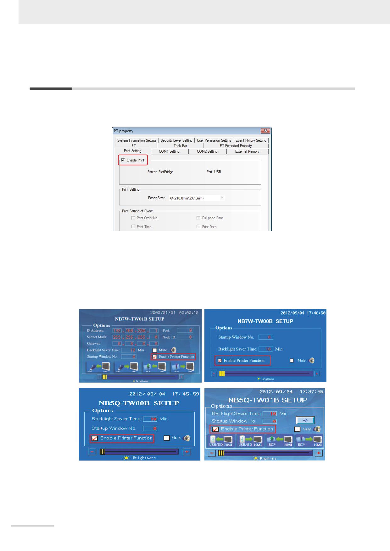
7 PictBridge Printing
7-2
Setting Method for Using Printing
Function
1 After the project being completed, compile it with the [Enable Print] option in the [Print Setting]
tab in the [PT Property] dialog box being checked.
2 Set the DIP switches SW1 and SW2 on the back side both to ON. Then press the Reset switch,
and restart the NB Unit to enter the System Setting Mode. Then download project to the NB Unit
after the compilation is completed.
3 Check the “Enable Printer Function” option to enable the printing operation.
The locations of “Enable Printer Function” in the System Setting Mode for different PTs (NB10W
is the same as NB7W, and NB3Q is the same as NB5Q.) are shown as follows:
4 Set the DIP switches SW1 and SW2 both to OFF, and restart the NB unit to enter the User
Project Mode.
5 Use the USB cable to connect the USB Slave port on the back side of NB Unit with the printer
for printing.
7-4
NB-series Programmable Terminals NB-Designer Operation Manual(V106)
7 PictBridge Printing
Note 1
The USB slave port on NB Unit is used for the upload/download and commissioning of program by
default, but in the User Project Mode, it will shift to a USB port only supporting the printing function
instead of other functions when the “Enable Print” option in the System Setting Mode is checked.
2
In the Downloader Mode or System Setting Mode, the function of using USB Slave port to download
always works properly without the influence of the above settings.
3
If the printer cannot work normally as a result of the NB Unit power-on, reset or other operations,
please restart the printer.
4
When the printing function cannot be used, refer to 6-3-1 Software Trouble in the NB Series Startup
Guide Manual for the solution.
The descriptions of USB Slave port in the User Project Mode:
[Enable Print] (set in the NB-Designer)
Setting Items
Checked
Unchecked
USB slave port is only for printing.
Since the project is not set in
[Enable Printer
Checked
printing mode, printing is not
Function] (set
available.
in the System
USB slave port can’t be used for
Since settings of the NB unit and
Setting Mode)
Unchecked
printing because it is in download
the project are not set in printing
mode.
mode, printing is not available.
In conclusion, the printing is available only after the printing function in NB-Designer and NB Unit
are both enabled.
7
NB-series Programmable Terminals NB-Designer Operation Manual(V106)
7-5
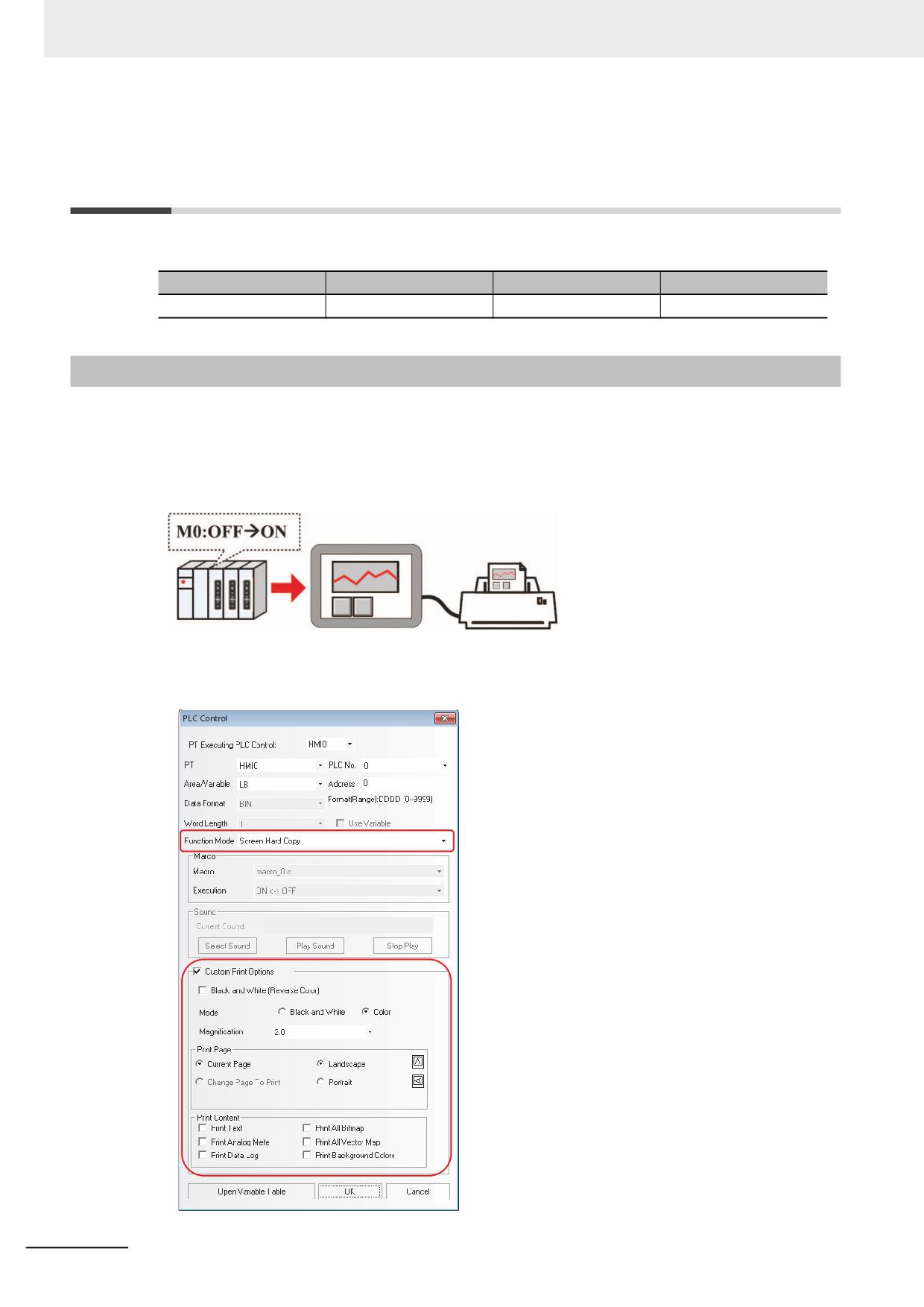
7 PictBridge Printing
7-3
Components Related to Printing and
Setup Descriptions
Related Components List
Component name
Function
Trigger address
Print contents
PLC Control
Screen Hard Copy
Bit
Prints the current screen
7-3-1
PLC Control
Screen Hard Copy
Screen Hard Copy is to control the printout of the current screen allocated to the bit address of PLC
control. When the address of the specified memory is turned from OFF to ON, the current screen
contents will be printed out.
The print content output mode setting:
Method 1: Check [Custom Print Options].
7-6
NB-series Programmable Terminals NB-Designer Operation Manual(V106)
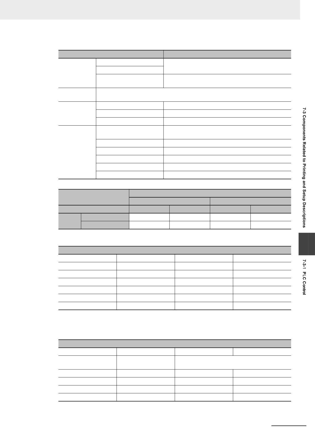
7 PictBridge Printing
Custom Print Options Properties Description:
Custom Print Options Properties
Details
Printer Color
Black and White
Only color printers support printer color change.
Color
Black and White
Prints the monochrome in reverse color.
(Reverse Color)
Magnification
It can be selected from 0.1 to 5.0 (Zoom Out printing may cause distortion, thus is not
recommended.)*
Print Page
Current Page
Print the current screen.
Landscape
print the content with landscape orientation.
Portrait
print the content with portrait orientation.
Print Content
Print Text
Prints the static texts and label characters on the current
screen.
Print Analog Meter
Prints the Analog Meter components on the current screen.
Print Trend Graph
Prints the Trend Graph on the current screen.
Print All Bitmap
Prints all the Bitmaps on the current screen.
Print All The Vector Map
Prints all the Vector Graphics on the current screen.
Print Background Colors
Prints the backg4round color of the current screen.
* Default Magnification (based on standard A4 paper):
PT Model
NB3Q/NB5Q -TWB
NB7W/NB10W-TWB
Print Direction
Landscape
Portrait
Landscape
Portrait
Display
Horizontal Display
4
3
2
1.4
Mode
Vertical Display
3
4
1.4
2
Method 2: Don't check Custom Print Options, and make the setting through the corresponding bits
of the system memories LW9054 and LW9055.
7
Lw9054 Settings
Bit No.
Name
0 (The bit is OFF)
1 (The bit is ON)
Bit 0
Print Text
Not print
Print
Bit 1
Print Analog Meter
Not print
Print
Bit 2
Print Trend Graph
Not print
Print
Bit 3
Print All Bitmap
Not print
Print
Bit 4
Print All The Vector Map
Not print
Print
Bit 5
Print Background Colors
Not print
Print
The value of LW9054 can be set with the Command Button component. If all contents on the PT
screen are to be printed, place the Command Button component to the Common Sheet. Select [Set
value when screen is loading] in the [Command Button] tab of the [Command Button Property],
specify [Set Value] to “255”, and specify LW9054 to a value allow all the content printed.
Lw9055 Settings
Bit No.
Name
0 (The bit is OFF)
1 (The bit is ON)
Bit 0~ Bit 7
Magnification
Ranges from 1 to 50 with the meaning of magnifying
0.1 to 5.0 times respectively.
Bit 8
Printer Color
Color
Black and White
Bit 9
Print Page
Prints the current page
System Reserved
Bit 10
Print Direction
Landscape
Portrait
Bit 12
Reverse Color Print
Normal Print
Reverse Color Print
[Example] To print the content in the current page with a magnification of 0.3 in monochrome, set
LW.B9055.0, LW.B9055.1 and LW.B9055.8 all ON, and LW.B9055.9 OFF; or set LW9055 to “259”.
NB-series Programmable Terminals NB-Designer Operation Manual(V106)
7-7

7 PictBridge Printing
7-4
List of System memories Related to
Printing
Local Bit (LB):
Address
Function description
Property
LB9016
Printer error indication.
Read only
ON: Error; OFF: Normal
LB9017
Printer control mask bit
Read /Write
ON: Disable; OFF: Enable (default).
All the print modes will be invalid when this bit is ON.
LB9132
Printer state.
Read only
ON: Busy; OFF: Idle.
LB9133
Pretreat for improve print effect.
Read /Write
ON: Pretreat; OFF: Direct Printing.
LB9143
USB printer connection status.
Read only
ON: Connect; OFF: Disconnect.
Local Word (LW):
Address
Function description
Property
LW9054
Printout format
Read/Write
Bit0: Text 0: not print; 1: print
Bit1: Analog Meter 0: not print; 1: print
Bit2: trend graph 0: not print; 1: print
Bit3: all bitmaps 0: not print; 1: print
Bit4: all vector Map 0: not print; 1: print
Bit5: Background Color 0: not print; 1: print
LW9055
Printout format
Read/Write
Bit0~Bit7: 1~50 show magnification 0.1~5.0
Bit8: Printer Color 0: Color; 1: Black and White
Bit9: Print Page 0: current page; 1: System Reserved
Bit10: Printer Directing 0: Landscape; 1: Portrait
Bit12: Reverse Color Enable 0: Normal; 1:Reverse
LW9800&LW9801
Current Error Codes
Read/Write
7-8
NB-series Programmable Terminals NB-Designer Operation Manual(V106)

7 PictBridge Printing
7-5
List of Error Codes for Printing
When the printing has some problems, error will occur in the system with the error codes displayed.
The error codes displayed include the following codes. The error codes will be displayed the PT screen
and stored in the system memory (lower words) and LW9801 (higher words).
Codes (Value)
Description
0x73000000
Normal status (default).
0x7300FFF9
Printer not ready
0x7300FFFA
Printer busy (Trigger another print job when printer is printing)
0x7300FFFB
Driver & UI Printer Settings Disable
0x7300FFFC
UI Printer Setting Disable
0x7300FFFD
USB Cable not Connect
0x7300FFFE
Others Reason
0x7300FFFF
Driver is not configured
0x73010000
Paper related error (default).
0x73010100
Paper is empty.
0x73010200
Load Error - paper not loaded correctly.
0x73010300
Eject Error - paper not ejected correctly.
0x73010400
Media Error - paper not detected, paper skewed, roll paper cannot be cut or torn-off.
0x73010500
Paper jam.
0x73010600
Paper nearly empty.
0x73010700
The combination of paper type and paper size is not supported, or paper set in Printer does
7
not match request.
0x73020000
Ink related reason (default).
0x73020100
Ink empty.
0x73020200
Ink low.
0x73020300
Waste ink error (waste-ink reservoir full).
0x73030000
Hardware-related error. (default)
0x73030100
Fatal error.
0x73030200
Service call.
0x73030300
Printer unavailable (performing maintenance or processing jobs).
0x73030400
Printer buffer memory full.
0x73030500
Lever error (lever position not correct).
0x73030600
Cover open.
0x73030700
No print unit (e.g., missing print head).
0x73030800
Ink Cover open.
0x73030900
No ink Cartridge.
0x73040000
File-related error. (default)
0x73040100
Printinfo error (the size of information set to <Printinfo> is too large.)
0x73040200
File decode error (picture format of specified image cannot be decoded).
NB-series Programmable Terminals NB-Designer Operation Manual(V106)
7-9
7 PictBridge Printing
7-6
Recommended Printer Models
Brand
Model
CANON
PIXMA iP4980
EPSON
Colorio PX-G5300
HP
HP 8500A, HP 8500A Plus
7-10
NB-series Programmable Terminals NB-Designer Operation Manual(V106)
8
Web Interface
This section describes Web Interface.
8-1
Defining Web Interface
8-2
8-2
Setup Web Interface on a PC
8-3
8-3
Connection Method and Each Page Function
8-4
8-4
URL List
8-9
8
NB-series Programmable Terminals NB-Designer Operation Manual(V106)
8-1
8 Web Interface
8-1
Defining Web Interface
NB Series Programmable Terminal provides Web Interface function which is accessible externally with
the use of a Web browser. Using Web Interface function allows monitoring and operating the NB Unit
screens from external device.
Precautions for Correct Use
Security of this function is subjected only to Password. Give due consideration to Network
configurations and exclude illegal access to accomplish the security.
In the Monitor mode, a password is not set initially. Set a password before you use the function,
if necessary.
In order to use the Web Interface function, you shall update PT kernel and Rootfs in the NB-Designer
Ver.1.30 or later. For the update method, refer to the 4-4 System Operation (Page 4-15).
• Targeted Model
NB-TW01B(-V1)
• Targeted Version
NB-Designer: V1.30 or later
Kernel: 1764 or later
Rootfs: 1932 or later
• Operation confirmed Web browser
Internet Explorer 8 (Windows)
Internet Explorer 9 (Windows)
Google Chrome 32.0.1700.107 m (Windows) *1
Firefox 27.0 (Windows)
Safari (iOS6)
*1
Uncheck the check box of Use JavaScript in Server Setting.
Additional Information
Select the compatibility display when browsing it with Internet Explorer 10 or later.
8-2
NB-series Programmable Terminals NB-Designer Operation Manual(V106)
8 Web Interface
8-2
Setup Web Interface on a PC
Perform following settings beforehand in order to use Web Interface function.
Setting User Name and Password for Web Interface function
Set the User Name and Password for using this function. For the details, refer to the 4-8 Web Inter-
face Operation (Page 4-21).
Enable Web Interface function
In order to enable the Web Interface function, embed the function which turns LB9175 ON to the
project. Additionally, the LB9175 setting is applied immediately. Restart is not necessary.
Additional Information
NB Web interface function establishes communication by conforming to HTTP 1.0. The session-
retaining function with the Keep alive function is not supported. A session begins per command.
Thus, the number of units that are connected concurrently is not limited.
However, when more than one PC are connected, a PC needs to wait until other PC processing
is done. Thus, response may become slow.
8
NB-series Programmable Terminals NB-Designer Operation Manual(V106)
8-3
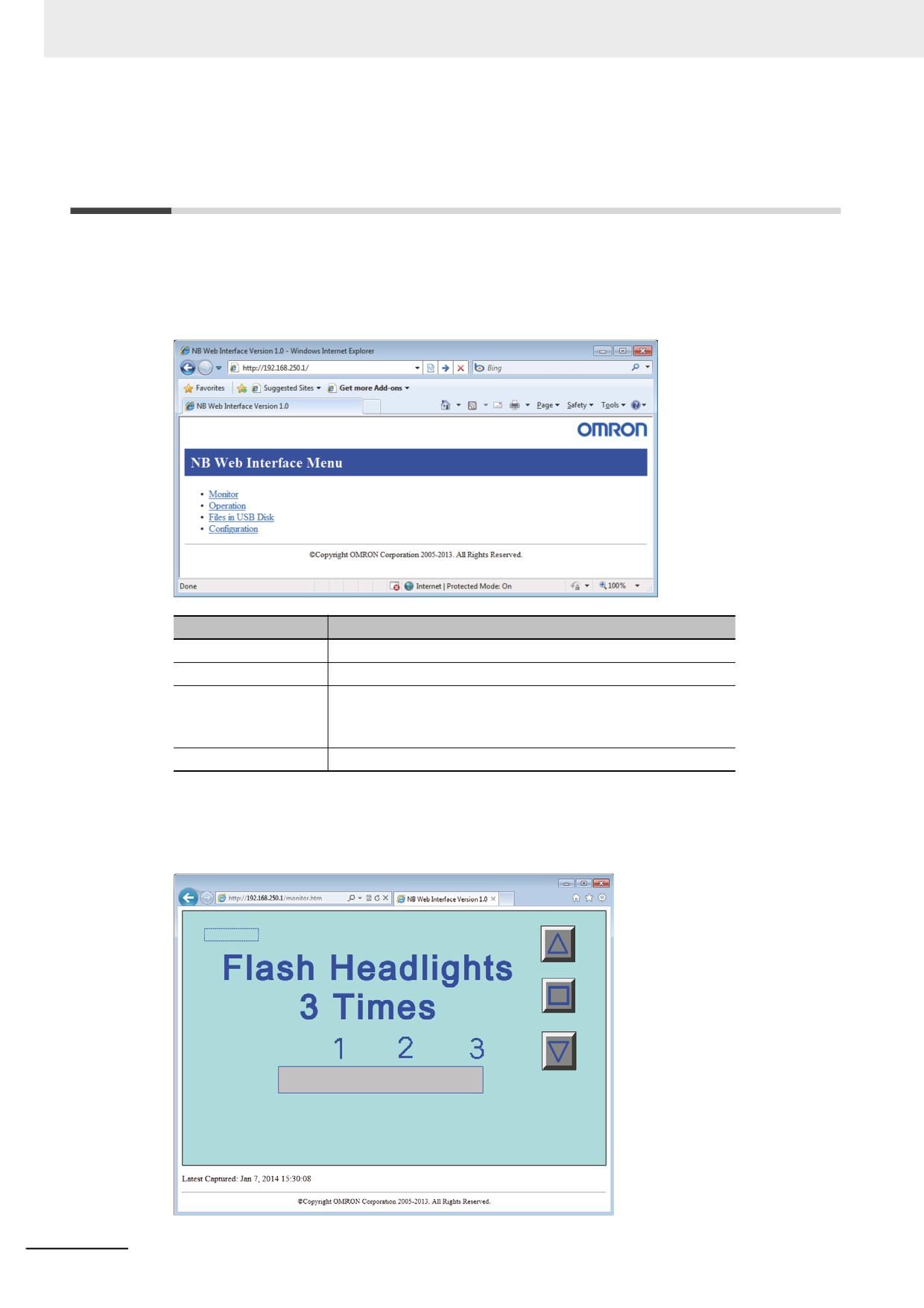
8 Web Interface
8-3
Connection Method and Each Page
Function
In order to access the NB Unit with the use of the Web browser, access http://[the NB Unit IP address]/. Initial
display of screen may be changed according to setting. However, Menu page is displayed in factory setting.
• Menu page
It is a page displayed by default at the time of shipment. Through this page, it is accessible to each page.
Function Name
Details
Monitor
It displays a monitoring page.
Operation
It displays an operation page.
Files in
It displays a file list in the USB Disk that mounts to the NB
USB Disk*1
Unit. Displaying the file contents and downloading the file
are available on Web browser.
Configuration
It displays a configuration page.
*1: Kernel 1764 or RootFS 2102 or higher is required.
• Monitoring page
It is a page to refer to the screen which is currently displayed on the NB Unit. A screen is updated at the inter-
val according to the setting. The screen displayed is not available to be operated with the monitoring page.
8-4
NB-series Programmable Terminals NB-Designer Operation Manual(V106)
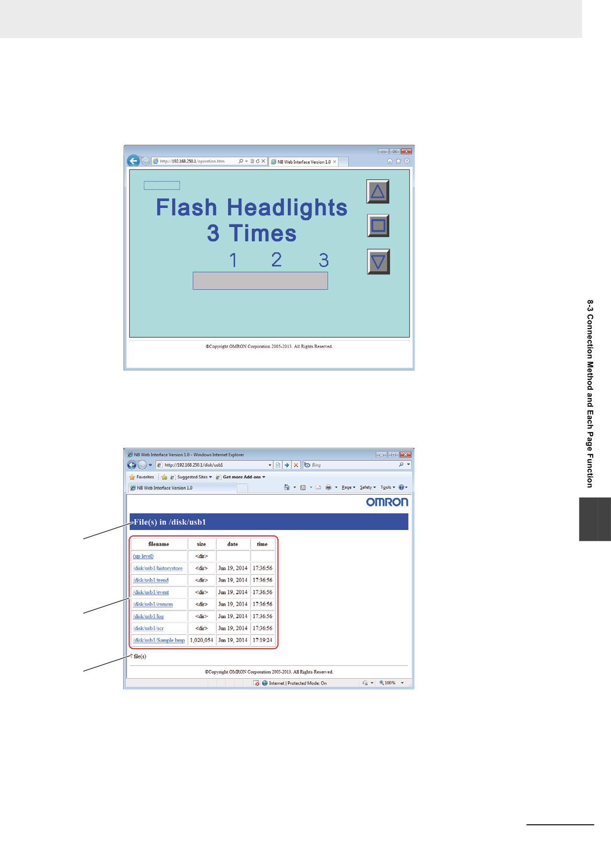
8 Web Interface
• Operation page
It is a page to operate the screen which is currently displayed on the NB Unit.
A screen is updated at the interval according to the settings. The screen displayed is available to
operate with the operation page.
• Files in USB Disk page
(1) File in the USB Disk page
The page of Files in USB Disk allows a file list of the USB Disk that mounts to the NB Unit
to be displayed. Also the page provides functions to display files on the file list and to down-
load such files with Web browser.
8
a
b
c
NB-series Programmable Terminals NB-Designer Operation Manual(V106)
8-5
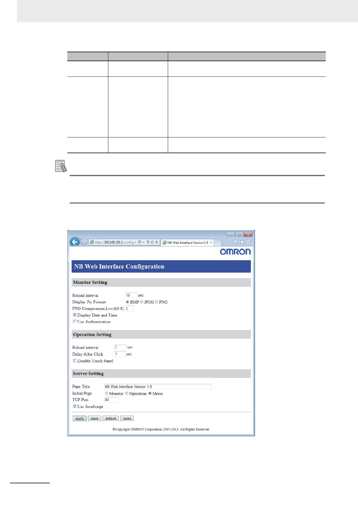
8 Web Interface
No
Item
Description
a
Folder
It displays the folder in the current USB Disk. The root folder of
the USB Disk is referred as "/disk".
b
File List
It displays a file list below the current folder.
In addition to the common usages of Web browser, it allows the
file contents to be displayed or the file to be downloaded.
The cells displayed with <dir> in the 'size' column indicates the
folders.
When you move from a folder to another one, click on the folder
name in the destination. When you move to the upper folder,
click on the (up level).
c
Total number of files
It displays total number of the files and folders that are currently
displayed.
Additional Information
Types of files to display directly are varied according to the Web browser. For any files that
cannot be displayed directly, it should be displayed with an appropriate application after
downloading the file once or install a plug-in or other.
• Configuration page
It is a page to perform setting regarding Web Interface.
8-6
NB-series Programmable Terminals NB-Designer Operation Manual(V106)

8 Web Interface
• Monitor Settings
Settings
Details
Reload Interval
Set refresh interval of Monitoring page display in the range between 2
and 99 sec.
Display Pic Format
Set format of a picture.
PNG Compression Level
Specify compression rate in the range between 0 and 8 when the
picture format is designated to PNG. As the number is greater, the
compression rate becomes higher.
Display Date and Time
When you need to display the date and time on the Monitoring page for
what you have obtained a screen, put a check in the checkbox of this
setting.
Use Authentication
When you directly specify URL for monitoring page followed by
perform user authentication, put a check in the checkbox of this
setting.
• Operation Settings
Settings
Details
Reload Interval
Set refresh interval of Operation page display in the range between 2
and 99 sec.
Delay After Click
Set waiting time to request next picture after clicking the screen on
Web browser.
Disable Touch Panel
Put a check in the checkbox of this setting when you need to prohibit
the operation of the NB Unit on Web browser.
• Server Settings
Settings
Details
Page Title
Set page title less than 64 characters. It supports only single-byte
alphanumeric characters.
Initial Page
Set the page displayed by default.
8
TCP Port
Set Port No. of TCP.
Use JavaScript
Put a check in the checkbox when you use JavaScript for refresh
processing of screen.
Functions
Details
Apply
The setting is applied by choosing this function. The setting data which
is applied with apply will be restored to the state before pressing apply
when the NB Unit is restarted.
Save
The setting is stored to and is applied to the NB Unit. The setting data
which is applied with save will be retained even though the NB Unit is
restarted.
Default
All the setting data will be restored to the state of factory setting.
Reset
All the setting data will be restored to the state before applying
changes.
NB-series Programmable Terminals NB-Designer Operation Manual(V106)
8-7
8 Web Interface
Additional Information
• The following characteristics are provided for the graphic formats which are selectable by Dis-
play Pic Format.
As the size of the graphics become larger, it takes longer to transfer the graphics. Then it takes
longer to refresh the screen. In accordance with the situations, select the optimal format.
Quality
Size
BMP
Fine
Large
JPEG
Bad
Small
PNG
Fine
Rather Large
• If Reload interval is too short, the transferring may be too late for displaying the graphic cor-
rectly.
Set the value in which should be considered the status of transferring pathway and others.
8-8
NB-series Programmable Terminals NB-Designer Operation Manual(V106)
8 Web Interface
8-4
URL List
Accessing the following URL when you use Web Interface allows you to access directly each page.
Page name
URL
Menu page
http://[the NB Unit IP address]/menu.html
Monitoring page
http://[the NB Unit IP address]/monitor.html
Operation page
http://[the NB Unit IP address]/operation.html
Files in USB Disk page
http://[the NB Unit IP address]/usbdisk.html
Configuration page
http://[the NB Unit IP address]/config.html
8
NB-series Programmable Terminals NB-Designer Operation Manual(V106)
8-9
A
pp
Appendices
A-1 List of Models
A-2
A-2 NB-Designer Function List
A-6
A-3 List of memories supported by OMRON PLC
A-11
A-4 Usage of Forced Address Bit
A-16
A-5 Lists for Supported OMRON PLC
A-17
NB-series Programmable Terminals NB-Designer Operation Manual(V106)
A-1
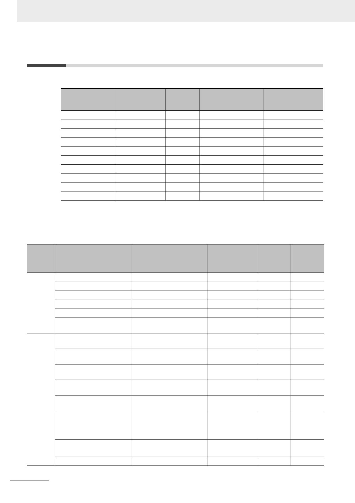
Appendices
A-1
List of Models
NB Unit
USB
Models
Resolution
Size
Communication
(Equivalent of USB
2.0 Full Speed)
NB3Q-TW00B(-V1)
QVGA 320×240
3.5 inches
COM1
Slave
NB3Q-TW01B(-V1)
QVGA 320×240
3.5 inches
COM1, Ethernet
Host, Slave
NB5Q-TW00B
QVGA 320×234
5.6 inches
COM1, COM2
Slave
NB5Q-TW00B-V1
QVGA 320×240
5.7 inches
COM1, COM2
Slave
NB5Q-TW01B
QVGA 320×234
5.6 inches
COM1, COM2, Ethernet
Host, Slave
NB5Q-TW01B-V1
QVGA 320×240
5.7 inches
COM1, COM2, Ethernet
Host, Slave
NB7W-TW00B(-V1)
WVGA 800×480
7 inches
COM1, COM2
Slave
NB7W-TW01B(-V1)
WVGA 800×480
7 inches
COM1, COM2, Ethernet
Host, Slave
NB10W-TW01B
WVGA 800×480
10.1 inches
COM1, COM2, Ethernet
Host, Slave
NB10W-TW01B-V1
WSVGA 1024×600
10.1 inches
COM1, COM2, Ethernet
Host, Slave
Units at the host side which can be connected using the serial port of the NB
Unit in the RS-232C mode through Host Link
OMRON PLC models supported by NB-TWB-V1 are limited. The table below shows
whether support is provided or not. “Yes” indicates supported, “No” indicates not supported.
CPU Unit that can be
Supported
Supported
PLC
CPU Unit with built-in Host
connected using Serial
Options required
by NB-
by NB-
Series
Link function
Communication
for connection
TWB-
TWB
Units/Boards
V1
CP
CP1L-L14/L20/M30/M40/M60
CP1W-CIF01
Yes
Yes
Series
CP1H-X40/XA40/Y20
CP1W-CIF01
Yes
Yes
CP1E-N14/N20
Yes
Yes
CP1E-N30/N40/N60/NA20
CP1E-N30/N40/N60/NA20
CP1W-CIF01
Yes
Yes
CP1L-EL20/EM30/EM40
CP1W-CIF01
Yes
Yes
CP2E-E14/E20/E30/E40/E60
CP2E-N14/N20/N30/N40/N60
CP1W-CIF01
Yes
Yes
CP2E-S30/S40/S60
CP2W-CIFD1/CIFD2 (*3)
C Series
C200HE-CPU42
C200HE-CPU32/42
C200HW-
Yes
Yes
C200HE-CPU42-Z
C200HE-CPU32/42-Z
COM02/04/05/06-V1
C200HG-CPU43/63
C200HG-CPU33/43/53/63
C200HW-
Yes
Yes
C200HG-CPU43/63-Z
C200HG-CPU33/43/53/63-Z
COM02/04/05/06-V1
C200HX-CPU44/64
C200HX-CPU34/44/54/64
C200HW-
Yes
Yes
C200HX-CPU44/64/65/85-Z
C200HX-CPU34/44/54/64/65/85-Z
COM02/04/05/06-V1
CPM1-10/20CDR-
Yes
No
+CPM1-CIF01
CPM1A-10/20/30/40CD-
Yes
No
+CPM1-CIF01
CPM2A-30/40/60CD-
Yes
No
+CPM1-CIF01
(When a peripheral port is
connected)
CPM2C-10/20-
Yes
No
(*1)
CQM1H-CPU11/21/51/61 (*2)
CQM1H-CPU51/61
CQM1H-SCB41
Yes
Yes
A-2
NB-series Programmable Terminals NB-Designer Operation Manual(V106)
Appendices
CPU Unit that can be
Supported
Supported
PLC
CPU Unit with built-in Host
connected using Serial
Options required
by NB-
by NB-
Series
Link function
Communication
for connection
TWB-
TWB
Units/Boards
V1
CS
CS1G-CPU42/43/44/45(-V1)
CS1G-CPU42/43/44/45(-V1)
CS1W-SCU21(-V1)
Yes
Yes
Series
CS1H-CPU63/64/65/66/67(-V1)
CS1H-CPU63/64/65/66/67(-V1)
CS1W-SCB21/41(-V1)
CS1G-CPU42H/43H/44H/45H
CS1G-CPU42H/43H/44H/45H
CS1W-SCU21(-V1)
Yes
Yes
CS1H-CPU63H/64H/65H/66H/67H
CS1H-CPU63H/64H/65H/66H/67H
CS1W-SCB21/41(-V1)
CJ Series
CJ1G-CPU44/CPU45
CJ1G-CPU44/CPU45
CJ1W-SCU21/41/-V1
Yes
No
CJ1W-SCU22/42
CJ1G-CPU42H/43H/44H/45H
CJ1G-CPU42H/43H/44H/45H
CJ1W-SCU21/41/-V1
Yes
No
CJ1H-CPU65H/66H/67H
CJ1H-CPU65H/66H/67H
CJ1W-SCU22/42
CJ1M-CPU11/12/13/21/22/23
CJ1M-CPU11/12/13/21/22/23
CJ1W-SCU21/41/-V1
Yes
No
CJ1W-SCU22/42
CJ2M-CPU31/32/33/34/35
CP1W-CIF01
Yes
Yes
CJ1W-SCU21/41/-V1
CJ1W-SCU22/42
CJ2M-CPU11/12/13/14/15
CJ2M-CPU11/12/13/14/15
CJ1W-SCU21/41/-V1
Yes
Yes
CJ1W-SCU22/42
CJ2H-CPU64/65/66/67/68(-EIP)
CJ2H-CPU64/65/66/67/68(-EIP)
CJ1W-SCU21/41/-V1
Yes
Yes
CJ1W-SCU22/42
NJ Series
NJ501/301/101
CJ1W-SCU22/42
Yes
Yes
NX
NX1P2
NX1W-CIF01
Yes
Yes
Series
*1: Connect using conversion cables (CPM2C-CN111 type or CS1W-CN114/118 type), the RS-232C adaptor
(CPM1-CIF01 type) or the RS-422A adaptor (CPM1-CIF11 type).
*2: The CQM1H-CPU11 model does not have the RS-232C port built in the CPU, therefore it requires a peripheral
port to be connected to a PT through a conversion cable (CS1W-CN118 type).
*3: CP2W-CIFD1 option board has 2 RS-232C serial ports with different protocols. Connection with NB HMI is
available only through Port 1.
Units at the host side which can be connected using the serial port of the NB
Unit in the RS-422A mode through Host Link
OMRON PLC models supported by NB-TWB-V1 are limited. The table below shows
whether support is provided or not. “Yes” indicates supported, “No” indicates not supported.
CPU Unit that can be
Supported
Supported
PLC
CPU Unit with built-in Host
connected using Serial
Options required
by NB-
by NB-
Series
Link function
Communication
for connection
TWB-
TWB
Units/Boards
V1
CP
CP1L-L14/L20/M30/M40/M60
CP1L-L14/L20/M30/M40/M60
CP1W-CIF11/CIF12
Yes
Yes
Series
CP1H-X40/XA40/Y20
CP1H-X40/XA40/Y20
CP1W-CIF11/CIF12
Yes
Yes
CP1E-N30/N40/N60/NA20
CP1E-N30/N40/N60/NA20
CP1W-CIF11/CIF12
Yes
Yes
CP1L-EL20/EM30/EM40
CP1W-CIF11/CIF12
Yes
Yes
(*2)
CP2E-N14/N20/N30/N40/N60
CP1W-CIF11/CIF12-V1
Yes
Yes
(*3)
NB-series Programmable Terminals NB-Designer Operation Manual(V106)
A-3
Appendices
CPU Unit that can be
Supported
Supported
PLC
CPU Unit with built-in Host
connected using Serial
Options required
by NB-
by NB-
Series
Link function
Communication
for connection
TWB-
TWB
Units/Boards
V1
C Series
C200HE-CPU32/42
C200HW-COM03/06-V1
Yes
Yes
C200HE-CPU32/42-Z
C200HG-CPU33/43/53/63
C200HW-COM03/06-V1
Yes
Yes
C200HG-CPU33/43/53/63-Z
C200HX-CPU34/44/54/64
C200HW-COM03/06-V1
Yes
Yes
C200HX-CPU34/44/54/64/65/85-Z
CPM1-10/20CDR-
Yes
No
+CPM1-CIF11
CPM1A-10/20/30/40CD-
Yes
No
+CPM1-CIF11
CPM2A-30/40/60CD-
Yes
No
+CPM1-CIF11
(When a peripheral port is
connected)
CPM2C-10/20-
Yes
No
(*1)
CQM1H-CPU51/61
CQM1H-SCB41
Yes
Yes
CS
CS1G-CPU42/43/44/45(-V1)
CS1W-SCB41(-V1)
Yes
Yes
Series
CS1H-CPU63/64/65/66/67(-V1)
CS1W-SCU31(-V1)
CS1G-CPU42H/43H/44H/45H
CS1W-SCB41(-V1)
Yes
Yes
CS1H-CPU63H/64H/65H/66H/67H
CS1W-SCU31(-V1)
CJ Series
CJ1G-CPU44/45
CJ1W-SCU31/41-V1
Yes
No
CJ1W-SCU32/42
CJ1G-CPU42H/43H/44H/45H
CJ1W-SCU31/41-V1
Yes
No
CJ1H-CPU65H/66H/67H
CJ1W-SCU32/42
CJ1M-CPU11/12/13/21/22/23
CJ1W-SCU31/41-V1
Yes
No
CJ1W-SCU32/42
CJ2M-CPU31/32/33/34/35
CP1W-CIF11/CIF12
Yes
Yes
CJ1W-SCU31/41-V1
CJ1W-SCU32/42
CJ2M-CPU11/12/13/14/15
CJ1W-SCU31/41-V1
Yes
Yes
CJ1W-SCU32/42
CJ2H-CPU64/65/66/67/68(-EIP)
CJ1W-SCU31/41-V1
Yes
Yes
CJ1W-SCU32/42
NJ Series
NJ501/301/101
CJ1W-SCU32/42
Yes
Yes
NX
NX1P2
NX1W-
Yes
Yes
Series
CIF11/CIF12
*1: Connect using conversion cables (CPM2C-CN111 type or CS1W-CN114/118 type), the RS-232C adaptor
(CPM1-CIF01 type) or the RS-422A adaptor (CPM1-CIF11 type).
*2: CP2E series units (CP2E-S30/S40/S60) with the Built-in RS-485 Port (2-wire) cannot be connected with the
NB via 2-wire RS-485.
*3: CP2W-CIFD3 communicates via the 2-wire RS-485 interface and it is not available for communications with
the NB.
A-4
NB-series Programmable Terminals NB-Designer Operation Manual(V106)
Appendices
Units at the host side which can be connected using the Ethernet port of the
NB Unit
OMRON PLC models supported by NB-TWB-V1 are limited. The table below shows
whether support is provided or not. “Yes” indicates supported, “No” indicates not supported.
CPU Unit that can be
Supported
CPU Unit with built-in
connected through adding
Supported
PLC
Options required
by NB-
Ethernet communication
Ethernet Communication
by NB-
Series
for connection
TWB-
function
Unit/optional
TWB
V1
communication board
CP
CP1L-L14/L20/M30/M40/M60
CP1W-CIF41
Yes
Yes
Series
CP1H-X40/XA40/Y20
CP1W-CIF41
Yes
Yes
CP1E-N30/N40/N60/NA20
CP1W-CIF41
Yes
Yes
CP1L-EL20/EM30/EM40
Yes
Yes
CP2E-N14/N20/N30/N40/N60
Yes
Yes
CS
CS1G-CPU42/43/44/45(-V1)
CS1W-ETN21
Yes
Yes
Series
CS1H-CPU63/64/65/66/67(-V1)
CS1W-EIP21
CS1G-CPU42H/43H/44H/45H
CS1W-ETN21
Yes
Yes
CS1H-CPU63H/64H/65H/66H/67H
CS1W-EIP21
CS1D-CPU65H/67H
CS1W-ETN21
Yes
Yes
CS1W-EIP21
CS1G-CPU43H/44H/45H
CS1W-EIP21S
Yes
Yes
CS1H-CPU63H/64H/65H/66H/67H
CS1D-CPU65H/67H
CJ Series
CJ1G-CPU42H/43H/44H/45H
CJ1W-ETN21
Yes
No
CJ1H-CPU65H/66H
CJ1W-EIP21
CJ1M-CPU11/12/13/21/22/23
CJ1W-ETN21
Yes
No
CJ1W-EIP21
CJ1H-CPU65H-R/66H-R/67H-R
CJ1W-ETN21
Yes
No
CJ1H-CPU65H/66H
CJ1W-EIP21
CJ2M-CPU11/12/13/14/15
CJ1W-ETN21
Yes
Yes
CJ2H-CPU64/65/66/67/68
CJ1W-EIP21
CJ1W-EIP21S
CJ2M-CPU31/32/33/34/35
Yes
Yes
CJ2H-CPU64/65/66/67/68(-EIP)
Yes
Yes
NJ Series
NJ501/301/101
Yes
Yes
NX
NX102
Yes
Yes
Series
NX1P2
NX502
No
Yes
NX701
No
Yes
NB-Designer information
Descriptions
Remarks
The software that creates
Each version of NB-Designer supports the following operating systems. (*1)
screen data for NB series
Windows 10 (32/64-bit)
PT.
Windows 11
The NB-Designer incorporates a transmission program and a standard system
program specified for the NB-series Units. To download application programs, please
access your local Omron website. If you do not find a local site, visit Omron IA global
site “http://www.ia.omron.com/” first, then select the area of your business.
*1. NB-Designer version 1.531 or lower supports the following operating systems:
Windows XP Service Pack 3 or later
Windows Vista, 7, 8, 8.1, and 10 (32/64-bit)
Related connecting objects
Cable with connectors (NB Unit ↔ PLC)
Models
Cable Length
Object Unit
Communications methods
Specifications
XW2Z-200T
2m
Units with 9-pin connectors
Host Link
9-pin ↔9-pin
XW2Z-500T
5m
by OMRON
(RS-232C)
NB-RSEXT-2M
2m
RS-422/485
Host Link
9-pin ↔5 wire
Communication Units by
(RS-422)
PLC manufactures
NB-series Programmable Terminals NB-Designer Operation Manual(V106)
A-5
Appendices
A-2
NB-Designer Function List
Items
Descriptions of Function
Parts
Bit Button
Operations such as the touch input allow the specified bit address turned
ON/OFF.
Bit Lamp
Indicates the specified ON/OFF state of one bit address.
Bit Switch
Operations such as touch input allow the specified bit address turned
ON/OFF. Specify the Read/Write addresses separately to operate them as
the lamp.
Command Button
Function Component performs several processing such as transmission of
constant value.
Word Lamp
Function Component switches the display status according to the change
with value of the communications address.
Word Switch
Function Component performs increase and decrease of the value or
transmission of the value selected from the list.
XY Graph
Describing a continuum from the value of the communications addresses as
each point of coordinates in the component area. The shape can be modified
dynamically.
Moving
Describing the vector graphics or the bit map from the value of the
Component
communications addresses as point of coordinates. The shape can be
modified dynamically.
Animation
Draw the component with the specified track in the PT, and this position is
determined by the value of the preset path and the communication
addresses.
Number Input
Display the specified value of the communication address. Also Entering
number by pop-up keyboard and pressing [ENTER] allow the communication
address modified.
Number Display
Display the value of the specified communication address.
Text Input
Set the value of the specified communication address to text string data. The
input data is saved to a consecutive memory with the “Read Address” as the
first address.
Text Display
Display the value of the specified communication address as text string.
Level Meter
Display the value of the specified communications address in a bar chart
percentage style according to the set maximum and minimum values.
Analog Meter
Display the value of the specified communication address by means of a
Analog Meter diagram.
Indirect Screen
Display the screen of the specified screen No. in pop-up screen.
Direct Screen
Display the specified screen in pop-up screen.
Alarm
Display the occurred alarm information in the specified area. The content
displayed by the Alarm Display component is the same as that displayed by
the Alarm component.
Data Log
Obtain the values of periodically specified communications address and
display them in the graphic chart. The backg4round communication still
continues to do when the current screen where the Data Log locates is
closed. Even after the switching the screen in which the Data Log component
located to another screen, if the screen in which Data Log component
located is refreshed, the sampling data which was obtained until switching
the screen can be displayed.
Recipe
Used to transfer the data from the recipe memory of PT to PLC or PLC data
to the PT Recipe memory.
Oscillograph
The Oscillograph functions similarly to the Data Log. But the data sampling
of the Oscillograph is valid only during the screen in which the Oscillograph
is located is displayed, which means that each time the screen is switched,
the sampling data will be deleted and a new sampling will be started.
A-6
NB-series Programmable Terminals NB-Designer Operation Manual(V106)
Appendices
Items
Descriptions of Function
Parts
Scroll Bar
Move the slider to modify the value of the specified communications address.
Event
Used to make the event information logged in “Event Information” and
meeting the current triggering conditions displayed.
Note Book
Used to modify or display the value of the specified communications
address. The input data is saved to a consecutive memory with the “Read
Address” as the first address.
Word Neon Lamp
Used to display the label contents in loopy moving way, and it supports the
label contents corresponding to 256 (max.) states in the loopy-moving way.
Bit Neon Lamp
Used to display the label contents in loopy moving way, and it supports the
label contents corresponding to State 0 and State 1 in the loopy-moving way.
Touch Trigger
This function allows the multiple components operated all at once. When the
communications addresses specified to the Touch Trigger component are
satisfied to the trigger conditions, the components placed in the valid area for
the Touch Trigger component can be triggered to act.
Table
Used to make the selection type of “Select by row”, “Select by column” and
“Select by cell”. The user can set the “Row”, “Column”, “Select Color”,
“Background Color”, “Border Color”, and write the selected Row No. and
Column No. into the specified communication address.
Data History
Read the consecutive addresses of the memory periodically with the top of
the specified communications address, and display in the table format.
Event History
It can be used to search or display the event history information, which is
Display
recorded in the “Event Setting” database and whose current state meets the
triggering conditions, in the table form. And this component works only
together with the external memory.
Operation Log
It can be used to record or display the PT operations in the table form. The
operation log will be stored into the external memory in CSV format. This
component works only together with the external memory.
Function
Scale
Draw the scale for the shapes such as portrait, landscape, arc, and circle.
Parts
Function Key
Used to provide functions such as “Switch Screens”, “Keyboard Function”,
“Execute Macro”, “Touch Calibration”, “Clear Event” and “Notepad” etc. The
function key cannot be controlled by the communication address. so the
execution of specified function needs to be activated by touching this
component.
Alarm Display
When the bit address specified with [Alarm Setting] matched to the trigger
condition, display the specified message. The message will be displayed in
loopy-moving way at the site where the alarm display is placed. The alarm
information will continue to scroll until this bit address is switched to the non-
alarm state.
Timer
When the specified duration is passed, other functions such as the Macro
execution, writing the value, or the data transmission are performed.
Bitmap
Used to call and display the bg-form graphics in the system graphics library
or the graphics library in project file window. The graphics in the formats such
as .jpg, .bmp, .gif, .png can be imported into the bitmap and displayed.
Vector Graphics
Call and display the graphics in vg format in system graphics library
displayed or project file window. Vector Graphics can be generated from the
file in “.JPG, .BMP, .GIF, or .PNG” formats.
Notepad
Draw the texts or graphics manually and freely in the specified area.
Data Transmission
Transmitting the value of the specified communication address to the other
communications address. Data Transmission can be triggered by the manual
touching method or the state change of the specified address.
FreePlotting
Draw the graphics with the pixel based on the consecutive data stored in the
specified communications addresses.
NB-series Programmable Terminals NB-Designer Operation Manual(V106)
A-7
Appendices
Items
Descriptions of Function
Function
Date/Time
Used to display the value of the RTC clock inside the PT in the set format.
Parts
Indirect Shape
Modifying the specified communications addresses allows the specifying
rectangle, ellipse, location and size of the lines to draw the shape.
User Information
Used to display the related information of the current login user in the table
form.
Multifunction
Used to incorporate the Bit Button component and Command Button
component into one component, thus making the user realize the Bit Set and
Word Set operations through only one key.
Event Display
Display the event information with [Event Setting] matching to the specified
trigger condition.
File List
The File List is used to display the file information of the external memory.
This component is divided into three parts: the left part displays the
information on the folder under the current folder, the upper-right part
displays the information on the file under the current folder, and the lower-
right part displays the PT information on the selected project file.
Project
Text Library
Specify the necessary text strings in advance, thus preventing the label with
Database
the same text from being input frequently.
Variable Table
It is a useful address library, which prevents the inconvenience resulting from
repeated input of address.
Alarm Setting
Specifying the message displayed in [Alarm] or [Alarm Display] and the bit
address and the trigger conditions applied to the trigger. If the bit address
registered to [Alarm Setting] matches the specified trigger condition, the
registered message will be displayed.
Event Setting
Specifying the function operated with the message displayed in [Event] or
[Event Display], the communications addressed which should be the trigger,
and the trigger condition. If the bit address or word address registered to the
[Event Setting] are matched the specified trigger condition, the registered
function can be operated or the registered message can be displayed.
PLC Control
Specify the communication address allocated to the specific functions as
follows. It is available to select among the screen switching, writing the data
(the current base screen) in the PLC, general PLC controlling, turning OFF
the back light, and turning ON the back light and others.
Screen
Base Screen
It is the general screen.
Type
Common Sheet
There is only 1 Common Sheet, which can be set to above or under the Base
Screen.
The maximum number of Base Screen ejected in 1 Common Sheet is up to
16.
Menu Screen
There is only 1 Menu Screen, which will appear only after “Menu” is touched.
Sheet Screen
Up to 3 Sheet Screens can be set for 1 Base Screen.
Pop-up Screen
The types are “Tracking”, “Modal”, “Clipping” and “Fixed”.
It can be displayed normally or in the top layer.
The maximum number of Pop-up Screen ejected in 1 Base Screen is up to
16.
Direct Screen
Up to 16 Direct Screens can be displayed simultaneously in 1 Base Screen.
It is controlled by the bit.
Indirect Screen
Up to 16 Indirect Screens can be displayed simultaneously in 1 Base Screen.
It is controlled by word.
Screen Property
Security level of the screen, screen attribute, backg4round color, transparency
rate, width and color of frame, location to place screen, size of screen (width
and height), sheet screen allocated to screen (three screens at max.), type of
pop-up used as pop-up can be specified.
A-8
NB-series Programmable Terminals NB-Designer Operation Manual(V106)
Appendices
Items
Descriptions of Function
Screen
Maximum Screen
It is up to 32768.
Number
Number
Screen No.
It includes 0 and 10 to 32767 (Base Screens)
1: Common Sheet (Default)
2: Menu Screen (Default)
3: NUM Keyboard (Default)
4: ASCII Keyboard (Default)
5: File List Screen (Reserved by system)
6: Password Screen (Reserved by system)
7: Confirmation Screen (Default)
8: HEX Keyboard (Default)
9: Login Screen (Default)
Screen Switching Method
The function of switching screen with [Function Key] allows switching the
displayed screen to optional base screen, common sheet screen, menu
screen, or pop-up screen.
Entering the optional screen No. to the communications address specified to
the function of switching screen with [PLC Control] allows switching the
screen to the screen with the entered screen No.
Macro Function
The function to create the simple original program by the user and to execute
it. The user can add the functions such a arithmetical operations or
discriminant of the conditions which are not be supported by the basic
functions of the NB-Designer. Using the Macro function, the user also
convert the display processing in the screen or the data processing used to
be performed in the PLC. This function allows the PC loading reduced. The
Macro of the NB-Designer conforms to C Language (ANSI C89).
Internal
LB
Refers to the local bit address of PT, which can’t be saved when power is
Address
OFF.
inside PT
RB
Refers to the absolute address of bit address saved in the recipe data that is
stored in the flash memory, even when the power turns OFF, the data can be
retained. Even if the battery is dead in PT, the data stored in the recipe
memory will not be lost.
RBI
Refers to the index address of bit address saved in the recipe data that is
stored in the flash memory, even when the power turns OFF, the data can be
retained. Even if the battery is dead in PT, the data stored in the recipe
memory will not be lost.
LW.B
Refers to the bit address corresponding to the local word address of PT,
which can’t be retained when the power is OFF.
FRB
Refers to the bit address to be stored in the flash memory, even when the PT
turns OFF, the stored data can be retained. When the battery is dead in PT,
the data saved in flash memory will not be affected.
FRBI
Refers to the index address of bit address saved in flash memory, which can
be retained when the power of PT turns OFF. When the battery is dead in PT,
the data saved in flash memory will not be affected.
LW
Refers to the local word address of PT, which can’t be retained when power
is OFF.
RW
Refers to the absolute address saved in the recipe data that is stored in the
flash memory, which can be retained when the power of PT turns OFF. Even
if the battery is dead in PT, the data stored in the recipe memory will not be
lost.
RWI
Refers to the index address saved in the recipe data that is stored in the
flash memory, which can be saved when the power is OFF. Even if the
battery is dead in PT, the stored data in the flash memory can be retained.
FRW
Refers to the word address stored in the flash memory, which can be
retained when the power of PT turns OFF. When the battery is dead in PT,
the data saved in flash memory will not be affected.
NB-series Programmable Terminals NB-Designer Operation Manual(V106)
A-9
Appendices
Items
Descriptions of Function
Internal
FRWI
Refers to the index address of word address saved in flash memory, which
Address
can be retained when the power of PT turns OFF. When the battery is dead
inside PT
in PT, the data saved in flash memory will not be affected.
ERW
Refers to the word address stored in the external memory, which can be
retained when the power of PT turns OFF. When the battery is dead in PT,
the data saved in external memory will not be affected.
File Formats
.rcp
It is the file format which is used by PT device.
Supported by
.frp
It is the file format of Recipe data saved and used in the flash memory of the
RecipeEditor
NB.
.csv
It can be imported/exported with Microsoft Excel or others.
Security Level
The security level is classified into 16 levels (0 to 15). The optional
passwords can be specified every one pasword for each level wit eight digits.
And the greater the level number, the higher the level. 15-level is the highest
and 0-level is the lowest. When the security level is 0, password cannot be
specified. The number of the security level is specified to “3” by default.
User Permission
User permission can be specified for 32 users at max. Also all the 32 kinds of
user permission can be specified for each user. The same user permission
can be specified to the multiple different users. The addition and deletion of
user or the modification of user permission settings can be performed on NB
units using system memory. The default valid time of user permission is 10
minutes. When 10 minutes passed after the login, this user permission will
be automatically cancelled, and the operation permission can be obtained by
inputting the password again.
Note Data saving into a flash memory such as RB/RW and FRB/FRW or an external memory such as ERW is per-
formed in accordance with CPU's processing load.
If turning off the power before saving, you may lose data because data is not instantly saved.
A-10
NB-series Programmable Terminals NB-Designer Operation Manual(V106)
Appendices
A-3
List of memories supported by OMRON PLC
Omron C Series
Device
Bit Address
Word Address
Format
Counter (Completion Flag)
C_FLAG 0-511
------
DDD
Timer (Completion Flag)
T_FLAG 0-511
------
DDD
Holding Area
H_bit 00.00-99.15
------
DD.DD
Data Area
D_bit 0000.00-6655.15
------
DDDD.DD
Link Area
LR_bit 00.00-63.15
------
DD.DD
Auxiliary Area
A_bit 00.00-27.15
------
DD.DD
CIO Area
CIO_IR_bit 000.00-511.15
------
DDD.DD
Counter Area
------
C 000-511
DDD
Timer Area
------
T 000-511
DDD
Holding Area
------
H 00-99
DD
Data Area
------
D 0000-6655
DDDD
Link Area
------
LR 00-63
DD
Auxiliary Area
------
A 0-27
DD
CIO Area
------
CIO_IR_word 000-511
DDD
Omron CJ/CS/NX Series
Device
Bit Address
Word Address
Format
CIO Area
CIO_bit 0000.00-6143.15
------
DDDD.DD
Work Area
W_bit 000.00-511.15
------
DDD.DD
Auxiliary Area
A_bit 000.00-11535.15
------
DDDDD.DD
Holding Area
H_bit 000.00-1535.15
------
DDDD.DD
Timer
T_Flag 0000-4095
------
DDDD
(Completion Flag)
Counter
C_Flag 0000-4095
------
DDDD
(Completion Flag)
Data Memory
D_bit 00000.00-32767.15
------
DDDDD.DD
Extension Data
E0_bit 0.00-32767.15
------
DDDDD.DD
Memory Area
…
(E0-E18)
E18_bit 0.00-32767.15
Extension Data
------
E0 0-32767
DDDDD
Memory(E0-E18)
…
E18 0-32767
CIO Area
------
CIO 0000-6143
DDDD
Work Area
------
W 000-511
DDD
Auxiliary Area
------
A 000-11535
DDDDD
Holding Area
------
H 000-1535
DDDD
Timer Area
------
T 0000-4095
DDDD
Counter Area
------
C 0000-4095
DDDD
Data Memory
------
D 00000-32767
DDDDD
Index memory Area
------
IR 00-15
DD
Data memory Area
------
DR 00-15
DD
NB-series Programmable Terminals NB-Designer Operation Manual(V106)
A-11
Appendices
Additional Information
As for the NX series, only NX1P2- is supported. To use the PLC, the settings for the
memory used for CJ-series Units are required. Make the settings on the Controller Unit.
Omron CP Series
Device
Bit Address
Word Address
Format
Work Area
W_bit 0.00-511.15
------
DDD.DD
Hold Area
H_bit 0.00-1535.15
------
DDDD.DD
Data Area
D_bit 0.00-32767.15
------
DDDDD.DD
Counter
C_Flag 0.00-4095.00
------
DDDD.DD
(Completion Flag)
Timer
T_Flag 0.00-4095.00
------
DDDD.DD
(Completion Flag)
Auxiliary
A_bit 0.00-959.15
------
DDD.DD
CIO Area
CIO_bit 0.00-6143.15
------
DDDD.DD
Work Area
------
W 0-511
DDD
Hold Area
------
H 0-1535
DDDD
Data Area
------
D 0-32767
DDDDD
Counter Area
------
C 0-4095
DDDD
Timer Area
------
T 0-4095
DDDD
Auxiliary Area
------
A 0-959
DDD
CIO Area
------
CIO 0-6143
DDDD
OMRON CJ/CS/NJ/NX Series Ethernet (UDP Slave)
Device
Bit Address
Word Address
Format
CIO Area
CIO_bit 0000.00-6143.15
------
DDDD.DD
Work Area
W_bit 000.00-511.15
------
DDD.DD
Auxiliary Area
A_bit 000.00-11535.15
------
DDDDD.DD
Holding Area
H_bit 000.00-1535.15
------
DDDD.DD
Timer
T_FLAG 0000-4095
------
DDDD
(Completion Flag)
Counter
C_FLAG 0000-4095
------
DDDD
(Completion Flag)
Data Memory
D_bit 00000.00-32767.15
------
DDDDD.DD
Extension Data
E0_bit 0.00-32767.15
------
DDDDD.DD
Memory Area
…
(E0-E18)
E18_bit 0.00-32767.15
Counter Release
C_RELEASE_STATUS
------
DDDD
Forced Status Area
0000-4095
Timer Release Forced
T_RELEASE_STATUS
------
DDDD
Status Area
0000-4095
Holding Release
H_RELEASE_STATUS
------
DDD.DD
Forced Status Area
0.00-511.15
Work Release Forced
W_RELEASE_STATUS
------
DDD.DD
Status Area
0.00-511.15
CIO Release Forced
CIO_RELEASE_STATUS
------
DDDD.DD
Status Area
0.00-6143.15
A-12
NB-series Programmable Terminals NB-Designer Operation Manual(V106)

Appendices
Device
Bit Address
Word Address
Format
Holding Set/Reset
H_FORCED_RELEASE
------
DDD.DD
Forced Release Area
0.00-511.15
Holding Forced
H_FORCED 0.00-511.15
------
DDD.DD
Set/Reset Area
Work Set/Reset
W_FORCED_RELEASE
------
DDD.DD
Forced Release Area
0.00-511.15
Work Forced
W_FORCED 0.00-511.15
------
DDD.DD
Set/Reset Area
CIO Set/Reset Forced
CIO_FORCED_RELEASE
------
DDDD.DD
Release Area
0000.00-6143.15
CIO Forced Set/Reset
CIO_FORCED
------
DDDD.DD
Area
0000.00-6143.15
Task Flag Area
TK_FLAG 0-127
------
DDD
Counter Set/Reset
C_FORCED_RELASE
------
DDDD
Forced Release Area
0000-4095
Counter Forced
C_FORCED
------
DDDD
Set/Reset Area
0000-4095
Timer Set/Reset
T_FORCED_RELASE
------
DDDD
Forced Release Area
0000-4095
Timer Forced
T_FORCED
------
DDDD
Set/Reset Area
0000-4095
Extension Data
------
E0 0-32767
DDDDD
Memory
…
(E0-E18)
E18 0-32767
EM Area
------
EM 0-32767
DDDDD
CIO Area
------
CIO 0000-6143
DDDD
Work Area
------
W 000-511
DDD
Auxiliary Area
------
A 000-11535
DDDDD
Holding Area
------
H 000-1535
DDDD
Timer Area
------
T 0000-4095
DDDD
Counter Area
------
C 0000-4095
DDDD
Data Memory
------
D 00000-32767
DDDDD
Index memory Area
------
IR 00-15
DD
Data memory Area
------
DR 00-15
DD
Task Flag Area
------
TK 00-127
DDD
Additional Information
As for the NX series, only NX102-, NX1P2- and NX502- are supported. To
use the PLC, the settings for the memory used for CJ-series Units are required. Make the set-
tings on the Controller Unit.
NB-series Programmable Terminals NB-Designer Operation Manual(V106)
A-13

Appendices
OMRON CP Series Ethernet (UDP Slave)
Device
Bit Address
Word Address
Format
CIO Area
CIO_bit 0000.00-6143.15
------
DDDD.DD
Work Area
W_bit 000.00-511.15
------
DDD.DD
Auxiliary Area
A_bit 000.00-959.15
------
DDD.DD
Holding Area
H_bit 000.00-1535.15
------
DDDD.DD
Timer
T_FLAG 0000-4095
------
DDDD
(Completion Flag)
Counter
C_FLAG 0000-4095
------
DDDD
(Completion Flag)
Data Memory
D_bit 00000.00-32767.15
------
DDDDD.DD
Counter Release
C_RELEASE_STATUS
------
DDDD
Forced Status Area
0000-4095
Timer Release Forced
T_RELEASE_STATUS
------
DDDD
Status Area
0000-4095
Holding Release
H_RELEASE_STATUS
------
DDD.DD
Forced Status Area
0.00-511.15
Work Release Forced
W_RELEASE_STATUS
------
DDD.DD
Status Area
0.00-511.15
CIO Release Forced
CIO_RELEASE_STATUS
------
DDDD.DD
Status Area
0.00-6143.15
Holding Set/Reset
H_FORCED_RELEASE
------
DDD.DD
Forced Release Area
0.00-511.15
Holding Forced
H_FORCED
------
DDD.DD
Set/Reset Area
0.00-511.15
Work Set/Reset
W_FORCED_RELEASE
------
DDD.DD
Forced Release Area
0.00-511.15
Work Forced
W_FORCED
------
DDD.DD
Set/Reset Area
0.00-511.15
CIO Set/Reset Forced
CIO_FORCED_RELEASE
------
DDDD.DD
Release Area
0000.00-6143.15
CIO Forced Set/Reset
CIO_FORCED
------
DDDD.DD
Area
0000.00-6143.15
Task Flag Area
TK_FLAG 0-31
------
DD
Counter Set/Reset
C_FORCED_RELEASE
------
DDDD
Forced Release Area
0000-4095
Counter Forced
C_FORCED 0000-4095
------
DDDD
Set/Reset Area
Timer Set/Reset
T_FORCED_RELEASE
------
DDDD
Forced Release Area
0000-4095
Timer Forced
T_FORCED
------
DDDD
Set/Reset Area
0000-4095
CIO Area
------
CIO 0000-6143
DDDD
Work Area
------
W 000-511
DDD
Auxiliary Area
------
A 000-959
DDD
Holding Area
------
H 000-1535
DDDD
Timer Area
------
T 0000-4095
DDDD
Counter Area
------
C 0000-4095
DDDD
Data Memory
------
D 00000-32767
DDDDD
Index memory Area
------
IR 00-15
DD
Data memory Area
------
DR 00-15
DD
Task Flag Area
------
TK 00-31
DD
A-14
NB-series Programmable Terminals NB-Designer Operation Manual(V106)

Appendices
Note
Name
Operation
Forced Reset
Turns OFF (0) the bit/flag and places it in forced status.
Forced Set
Turns ON (1) the bit/flag and places it in forced status.
Forced Set/Reset OFF Release
Turns OFF (0) the bit/flag and releases the forced status.
Forced Set/Reset ON Release
Turns ON (1) the bit/flag and releases the forced status.
Forced Set/Reset Release
Releases the forced status while retaining the ON/OFF status.
NB-series Programmable Terminals NB-Designer Operation Manual(V106)
A-15
Appendices
A-4
Usage of Forced Address Bit
When the OMRON PLC is connected via Ethernet, there are some special bit addresses:
_FORCED, _FORCED_RELEASE and _RELEASE_STATUS.
Usage example:
W_FORCED, W_FORCED_RELEASE and W_RELEASE_STATUS function as follows:
W_FORCED will enforce the address bit to 0 or 1, and then retain it in the forced status.
W_FORCED_RELEASE will enforce the address bit to 0 or 1, but it releases the forced state.
W_RELEASE_STATUS will release the forced status and make no change.
Usage example:
Place two Bit Switch components and one Bit Button component with settings as follows:
Switch No.
Component Name
Address
Switch Type
1
Bit Switch
W_FORCED 0.00
Alternate
2
Bit Switch
W_FORCED_RELEASE 0.00
Alternate
3
Bit Button
W_RELEASE_STATUS 0.00
Set
Perform the test:
Operation 1:
Firstly, touch switch 1 to specify the value to “0 (forced)” and then touch switch 2 to modify the value to
“1” and it causes the bit to be released of the forced state at the same time. Also when the bit is
specified to “1 (forced)” with switch 1, touch switch 2 to modify the bit to “0” and is causes the bit to be
released of the forced state at the same time.
Operation 2:
Firstly, touch switch 1 to specify the value to “0 (forced)” and then touch switch 3, but the bit will be
remained as “0” and it causes the bit to be released of the forced state. Also when the bit is specified to
“1 (forced)”, touch switch 3, but the bit will be remained as “1” and it causes the bit to be released of the
forced state.
Descriptions:
From the above results, it can be concluded that the difference between W_FORCED_RELEASE and
W_RELEASE_STATUS is: the former sets the value of address bit to 0 or 1, and then releases its
forced status, while the latter only releases the forced status of address bit without changing its value.
As W_FORCED_RELEASE is readable and writable, you can allocate it as readable and writable bit.
As W_RELEASE_STATUS is write-only, do not allocate it to reading status processing (e.g. Reading
the ON/OFF status of lamps and switches).
A-16
NB-series Programmable Terminals NB-Designer Operation Manual(V106)
Appendices
A-5
Lists for Supported OMRON PLC
NB-TWB
Refer to A-1 List of Models (Page A-2) for details on models supported by those other than G9SP.
Names Displayed in NB-Designer
PLC Models
Omron C Series
C200HX/HG/HE(-Z)
CQM1H
CPM1/2
Omron CJ/CS/NJ Series
CS1W-SCU21/31
CS1W-SCB21/41
CS1
CJ1W-SCU21/22/31/32/41/42
CJ1
CJ2
NJ01
Omron CP Series
CP1H/L/E
CP2W-CIFD
CP2E
Omron NX1 Series Host Link
NX1P2-
Omron CJ/CS/NJ Series Ethernet (UDP Slave)
CS1W-ETN21/EIP21/EIP21S
CJ1W-ETN21/EIP21/EIP21S
CJ2H--EIP
CJ2M-CPU3
NJ01-
Omron NX Series Ethernet (UDP Slave)
NX102-
NX1P2-
Omron CP Series Ethernet (UDP Slave)
CP1L-EM
CP1L-EL
CP1W-CIF41
CP1H
CP1L
CP2E
OMRON G9SP
G9SP-N10S
G9SP-N10D
G9SP-N20S
NB-series Programmable Terminals NB-Designer Operation Manual(V106)
A-17
Appendices
NB-TWB-V1
Refer to A-1 List of Models (Page A-2) for details on models supported by those other than G9SP.
Names Displayed in NB-Designer
PLC Models
Omron C Series
C200HX/HG/HE(-Z)
CQM1H
Omron CJ/CS/NJ Series
CS1W-SCU21/31
CS1W-SCB21/41
CS1
CJ1W-SCU22/32/42
CJ2
NJ01
Omron CP Series
CP1H/L/E
CP2W-CIFD01/02/03
CP2E
Omron NX1 Series Host Link
NX1P2-
Omron CJ/CS/NJ Series Ethernet (UDP Slave)
CS1W-ETN21/EIP21/EIP21S
CJ1W-ETN21/EIP21/EIP21S
CJ2H--EIP
CJ2M-CPU3
NJ01-
Omron NX Series Ethernet (UDP Slave)
NX102-
NX1P2-
NX502-
Omron CP Series Ethernet (UDP Slave)
CP1L-EM
CP1L-EL
CP1H-EX
CP1W-CIF41 (Mount on CP1)
CP2E
OMRON G9SP
G9SP-N10S
G9SP-N10D
G9SP-N20S
Omron NJ/NX Series EtherNet/IP (Tag variable access)
NJ01-
(TCP Slave)
NX102-
NX1P2-
NX502-
NX701-
A-18
NB-series Programmable Terminals NB-Designer Operation Manual(V106)

Revision History
A manual revision code appears as a suffix to the catalog number on the front cover of the manual.
Cat. No. V106-E1-
Revision code
Revision code
Date
Revised content
01
October 2011
Original production
02
February 2012
Changes related to battery.
03
April 2012
Adding descriptions of new functions added into NB5Q/NB7W-TW01B model
and the related contents.
04
August 2012
Adding descriptions and functions of NB3Q-TW00B/TW01B and NB10W-
TW01B models.
05
October 2012
Manual correction and updating.
06
December 2012
• Correction related to the backlight lamp, rubber packing and battery maintenance.
• Adding descriptions of the PictBridge printing function
07
December 2012
• Adding descriptions of the power supply and wire connection in Precautions
for Safe Use.
• Correcting descriptions of the memories related to printing.
• Adding contents to the list of error codes for printing.
08
April 2013
Changes and corrections
09
August 2013
Changes and corrections
10
February 2014
Changes and corrections
11
July 2014
This is a revision accompanied with adding a function to Web Interface.
12
July 2016
Changes and corrections
13
October 2016
Changes and corrections
14
November 2016
Changes related to OS.
15
March 2017
Changes and corrections
16
December 2017
Changes and corrections
17
April 2018
Changes and corrections
18
October 2018
Changes and corrections
19
April 2019
Changed and corrections
20
November 2019
Changes and corrections
21
June 2020
Changes and corrections
22
October 2020
Changes and corrections
23
August 2022
Adding warnings of Safety Precautions
24
March 2023
Adding descriptions of NB3Q/NB5Q/NB7W/NB10W-TWB-V1.
25
September 2023
Changes and corrections
26
July 2024
Changes and corrections
27
October 2025
Changes and corrections
28
April 2026
Adding descriptions of the connection method to OMRON PLCs using tag
variable access.
NB-series Programmable Terminals NB-Designer Operation Manual(V106)
Revision-1