Dubai Building Code (2021) - page 12
 

  Index      Manuals     Dubai Building Code (2021)


Search            copyright infringement  


Content      ..     10      11      12      13     ..


Dubai Building Code (2021) - page 12


Dubai Building Code

Part D: Vertical transportation

D 38

D.9.8.2 

Acceleration and jerk

Lower acceleration and jerk values provide better 

perceived comfort for passengers. Table D.39 gives 

recommended maximum values.

For bed elevators, acceleration shall not exceed 


0.6 m/s

2

 and jerk shall not exceed 1.0 m/s

3

.

Speed (m/s)

Acceleration (m/s

2

) Jerk (m/s

3

)

1

0.7

0.8

1.5 to 1.75

0.8

0.9

2.0 to 2.5

0.9

1

3.0 to 4.0

1

1.1

≥5

1.2

1.4

Table D.39  Recommended maximum acceleration and jerk at a given 

speed

D.9.8.3 

Destination control systems

Conventional elevator control systems are the most user-friendly, but they can be less efficient compared to 

destination dispatch (DD)/hall call destination control (HCDC), or a destination control system (DCS).
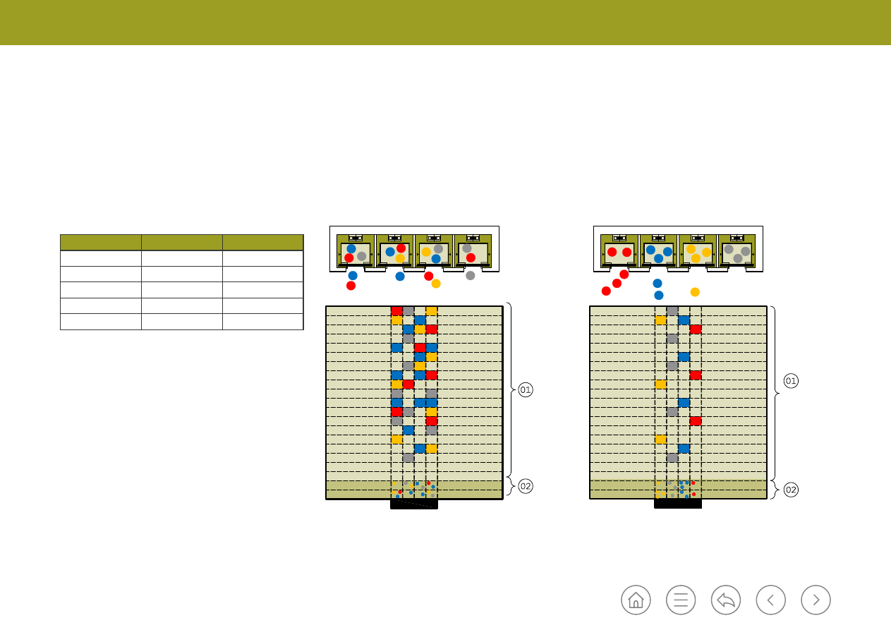
Figure D.25 illustrates a conventional control system and Figure D.26 illustrates a DCS. In a DCS, the passenger 

enters the destination floor before entering the cabin. The terminal shows floor numbers or a telephone keypad.

Key

01: Typical floors

02: Boarding floors

Figure D.25 

Conventional control system

Figure D.26 

Destination control system

Dubai Building Code

Part D: Vertical transportation

D 39

A DCS is preferred under the following conditions.
a) 

The elevators in the group do not serve an equal number of stops/floors. 

b) 

The up-peak traffic is demanding. 

c) 

There are multiple function areas in floors/mixed use buildings. 

d) 

Tenants and visitors enrol to get into the building/office premises.

A DCS offers the following advantages over a conventional control system.
1)  It improves the time to destination by grouping people travelling to the same 

floors at learned intervals.

2)  It results in organized lobby space, allowing more people to wait in the lobby.
3)  It is able to perform express travel with fewer intervening stops.
4) 

It improves system efficiency and handling capacity, allowing a group of 

elevators to transport more passengers in a fixed period of time. 

5)  It allows terminals to be mounted away from the elevator lobby, reducing 

congestion in the elevator lobbies.

A DCS offers the following disadvantages over a conventional control system.
i)  It has a relatively lower performance during the lunchtime peak.
ii) 

For correct and efficient operation of a DCS, each passenger needs to enter their 

destination and not tail-gate. Groups of people tend to allow one person to enter 

the destination floor, which means the DCS computes that there is only one 

person when there could be two, three or more persons.

iii)  It is not user-friendly for people unfamiliar with the system. A passenger getting 

into the wrong elevator has to exit and take another elevator to reach their 

destination. 

Table D.40 sets out building types that benefit from a DCS compared to a 

conventional control system. 

Building type

Conventional system

Destination control system

Residential apartment – occupants are 

familiar with the elevator system

P

P

Office – occupants are familiar with the 

elevator system

P

P P

Hotel – occupants are unfamiliar with the 

elevator system

P

-

Hotel apartment – occupants are 

unfamiliar with the elevator system

P

-

Educational building – stairs are relied 

upon to move between classes

P

-

Healthcare building (staff area) – 

occupants are familiar with the elevator 

system

P

P

Healthcare building (all other areas) – 

mixture of occupants who are familiar and 

unfamiliar with the elevator system

P

-

Table D.40  Recommendations for destination control systems in buildings

D.9.8.4 

Hybrid systems

A hybrid system (historically called an up-peak booster) combines destination control 

at the main boarding floor with conventional elevator controls at other floors. A 

hybrid system should be used where it is necessary to overcome lag in a DCS during 

peak lunchtime occupant circulation.

Dubai Building Code

Part D: Vertical transportation

D 40

D.10  Annex: Vertical transportation design summaries and report template

D.10.1  Vertical transportation selection 

summary – Design method 1

Vertical transportation selection summary (Design method 1)

Project name

Form number

Location

Date

Plot no.
Client
Architect
Project type

Project classification

Design

Authority

Estimated population
Number of groups

Occupiable floors
Boarding floors including main lobby

Number of passenger elevators based on 

population
Number of passenger elevators based on 

boarding floors
Number of dedicated firefighting 

elevators
Number of dedicated service elevators
Number of other elevators
Total elevators in the project
Number of escalators in the project 
Number of moving walks in the project

Authority section

Comments

Reviewed by

Dubai Building Code

Part D: Vertical transportation

D 41

D.10.2  Vertical transportation design summary – Design method 2

Vertical transportation performance approval summary (Design method 2)

Project name

Plot #

Form #

Location

Date

Client
Architect
Project type

Project classification

Is there a  VT Consultant 

involved?

yes

no

Group 1

Morning 

peak

Lunch 

peak

Evening 

peak

Estimated 

population

Handling capacity 

HC5%

Occupiable floors

Average waiting 

time (s)

Boarding floors 

including main lobby

Average destination 

time (s)

Group 1 Group 2 Group 3

Group 2

Morning 

peak

Lunch 

peak

Evening 

peak

Capacity

Handling capacity 

HC5%

Speed

Average waiting 

time (s)

Door open time

Average destination 

time (s)

Door closing time
Acceleration
Jerk

Group 3

Number of 

passenger elevators

Morning 

peak

Lunch 

peak

Evening 

peak

Number of 

passenger elevators/

fire/service elevators

Handling capacity 

HC5%

Number of dedicated 

firefighting elevators

Average waiting 

time (s)

Number of dedicated 

service elevators

Average destination 

time (s)

Number of other 

elevators
Total elevators in the 

project 
Total number of 

escalators in the 

project 
Total number of 

moving walks in the 

project 

Declaration: The vertical transportation system in the project is designed within the recommended 

parameters, and the parameters selected shall be met by suppliers approved in the UAE.

Remarks by VT Consultant/Lead Consultant

Authority section

Comments:

Reviewed by

Approved by

Dubai Building Code

Part D: Vertical transportation

D 42

D.10.3  Vertical transportation report template for VT Consultants

Table D.41 gives a summary of the minimum information required in the report.

Summary of vertical transportation (VT) design report
Section A

Main report

A1

Purpose of the report

A2

Project overview

A3

Assumptions

A4

Design of vertical transportation (VT) system

A5

Design elements for residences

A6

Definitions of design parameters

A7

Selection of passenger elevators

A8

Selection of firefighting elevator

A9

Selection of service and other elevators

A10

Conclusions and recommendations

Section B

Annexures

B1

Codes and requirements of Authorities 

B2

Traffic analysis

B3

Planning information

B4

Requirements from Authorities 

Table D.41  Summary of vertical transportation (VT) design report

Dubai Building Code

Part E: Building envelope

E 2

E.1  Performance statements

Performance statement

The performance statement will be met 

by following the requirements of:

The building envelope shall safely resist 

the loads imposed upon it. 

E.4

The building envelope shall reduce the 

energy required to cool the building.

E.5

The building envelope shall control 

moisture to protect the building, its 

users, its mechanical systems and its 

contents from physical or chemical 

damage.

E.7

The building envelope shall provide 

external noise protection to occupants.

E.8

The building envelope shall provide 

glazing that safely resists impact, whilst 

incorporating measures to prevent 

occupants colliding with the glazing.

E.9

The building envelope shall provide 

a safe means of opening and closing 

windows.

E.9

The building envelope shall adequately 

guard against the spread of fire.

E.10

The building shall provide safe access 

for cleaning and maintenance of the 

building envelope.

E.12

Dubai Building Code

Part E: Building envelope

E 3

E.2 

Definitions

E.2.1 

Terms

Building elevation:


View showing the image of one side 

of the building. A flat representation of one façade.

Building envelope:


Physical barrier between the 

exterior and the conditioned environment of a building 

to resist air, water, moisture, heat, cold, light, and noise 

transfer. For an air-conditioned building, the building 

envelope comprises the elements of a building that 

separate conditioned spaces from the exterior. Crown 

extensions to the façade to cover plant screen cladding 

are part of the building envelope. The building envelope 

does not include the physical barrier below ground.

Building maintenance unit:

 Permanently installed 

unit that provides easy and safe access to the building 

envelope for maintenance, inspections and cleaning. 

Containment:

 Glass barrier resisting penetration and 

preventing people from falling even after failure or 

breakage. 

Damp-proof course: 

Layer of waterproof material or 

construction in the wall of a building near the ground, 

primarily to prevent rising damp.

Damp-proof membrane: 

Material applied to prevent 

moisture transmission.

Drained air space: 

Air layer within a wall that allows 

any entering water or moisture to be drained out.

Glazed element: 

Individual element within a building 

envelope that lets in light, including windows, plastic 

panels, clerestories, skylights, doors that are more than 

one half glass, and glass block walls.

Glazing: 

Glass that is installed as one of the 

components of a wall, floor, ceiling or roofing system.

Gross wall area: 

Area of the wall that provides the 

thermal barrier of the building. It includes the solid 

area and any openings in the wall, such as doors 

or windows. It is the actual measured area, not the 

projected area on a drawing.

Groundwater pressure: 

Pressure of groundwater held 

within a soil or rock, in gaps between particles.

Guardrail: 

Vertical protective barrier erected along 

elevated walking surfaces, exposed edges of stairways, 

balconies and similar areas that minimizes the 

possibility of fall from elevated surfaces to lower level.

High-rise building: 

Building height greater than or 

equal to 23 m and up to 90 m, measured in accordance 

with the UAE FLSC 

[Ref. E.1]

. A more detailed 

definition is given in UAE FLSC.

Interstitial condensation: 

Condensation which occurs 

within or between layers of a construction.

Light transmittance:

 Percentage of incident light 

that passes through the glazed elements. When this 

percentage increases, the amount of daylight that 

passes into the building will increase.

Low-rise building: 

Building height less than or up to  

15 m, measured in accordance with the UAE FLSC 


[Ref. E.1]

. A more detailed definition is given in 


UAE FLSC.

Manifestation:

 Clear markings on transparent glazing 

to enable occupants to see the glazing as a hazard to 

be avoided.

Mid-rise building:

 Building height greater than 15 m 

but less than 23 m, measured in accordance with the 

UAE FLSC 

[Ref. E.1]

. A more detailed definition is 

given in UAE FLSC.

Moisture:

 Water or other liquid diffused in a small 

quantity as vapour, within a solid, or condensed on a 

surface.

Mould: 

Type of fungus that grows on damp or decaying 

material surfaces.

Operational forces: 

Forces sustained by the building 

envelope during operation of the building, e.g. impact 

from equipment or occupants. 

Rope access or abseiling: 

Form of work positioning 

that allows rope access technicians to descend, 

ascend and traverse ropes for access and work while 

suspended by their harness.

Shading coefficient (SC): 

Ratio of solar heat gain at 

normal incidence through glazing to that occurring 

through an approximately 3 mm thick clear float glass.

Dubai Building Code

Part E: Building envelope

E 4

Shading device: 

Projecting fixture that extends outside 

the external wall of any building, or a cover (such as 

a louver), to protect any door or window from rain or 

solar effect. 

Skylight or overhead glazing: 

Glass or other 

transparent or translucent glazing material installed at 

a slope of 15° or more from vertical.

Solar reflectance index (SRI):

 Index that combines 

reflectivity and emissivity, measuring a material’s 

ability to reject solar heat. SRI is defined such that a 

standard black (reflectance 0.05 and emittance 0.90) is 

0 and a standard white (reflectance 0.80 and emittance 

0.90) is 100. Materials with higher SRI absorb less heat 

and can reduce heat island effect.

Solid metal panels:

 factory manufactured panel 

consisting of solid metal skin or skins without a core. 

Solid metal panels could be aluminium, steel, copper, 

zinc, stainless steel, titanium, etc.

Surface condensation: 

Condensation which occurs on a 

visible surface within a building.

Super high-rise building: 

Building height greater than 

90 m, measured in accordance with the UAE FLSC 


[Ref. E.1]

. A more detailed definition is given in 


UAE FLSC.

Thermal bridge: 

Component or assembly of 

components penetrating through an otherwise 

continuous thermal line through which heat is 

transferred at a substantially higher rate than through 

the surrounding envelope areas. Examples could be a 

metal fastener, concrete beam, balcony slab or column. 

Thermal insulation: 

Materials/products or the 

methods and processes used to reduce heat transfer. 

Heat energy can be transferred by conduction, 

convection or radiation. The flow of heat can 

be delayed by addressing one or more of these 

mechanisms and is dependent on the physical 

properties of the material employed to do this.

Thermal transmittance:

 Rate of transfer of heat 

through a material(s) or assembly, expressed as a 

U-value.

Vapour resistance layer: 

Material layer within a wall or 

roof build-up with a high resistance to moisture vapour.

Window-to-wall ratio (WWR):

 Percentage determined 

by dividing the glazed area by the total external wall 

area of the building envelope. WWR can be calculation 

per orientation or per entire building.

Dubai Building Code

Part E: Building envelope

E 5

E.2.2 

Acronyms and abbreviations

ANSI

American National Standards Institute

ASCE

American Society of Civil Engineers

ASHRAE

American Society of Heating, Refrigeration, and 

Air-Conditioning Engineers

ASTM

ASTM International 

BMU

building maintenance unit

BRE

Building Research Establishment

BS

British Standard 

BS EN

British Standard European Norm

CFR

Code of Federal Regulations

Ch.

chapter

CPSC

Consumer Product Safety Commission 

CWCT

Centre for Window and Cladding Technology

DCD

Dubai Civil Defence

ETA

European technical assessment 

FFL

finished floor level

FM

Factory Mutual

IBC

International Building Code

IRATA

Industrial Rope Access Trade Association

ISO

International Organization for Standardization

NFPA

National Fire Protection Association

PV

photovoltaic 

SRI

solar reflectance index

TN

technical note

UAE FLSC

UAE Fire and Life Safety Code of Practice

UL

Underwriters Laboratories

WWR

window to wall ratio

Dubai Building Code

Part E: Building envelope

E 6

E.3  References

E.3.1 

Essential references

ANSI Z97.1, Safety glazing materials used in buildings
ASCE/SEI 7-16, Minimum design loads and associated 

criteria for buildings and other structures

ASHRAE 90.1:2019, Energy standard for buildings 

except low rise residential buildings
ASTM D1929, Standard test method for determining 

ignition temperature of plastics
ASTM E1300, Standard practice for determining load 

resistance of glass in buildings

ASTM E108, Standard test methods for fire tests of 

roof coverings

ASTM E119, Standard test methods for fire tests of 

building construction and materials
BS 5250, Code of practice for control of condensation 

in building

BS 6262-4, Glazing for buildings – Part 4: Code of 

practice for safety related to human impact
BS 8102, Code of practice for protection of below 

ground structures against water from the ground

BS 8414-1, Fire performance of external cladding 

systems – Part 1: Test method for non-loadbearing 

external cladding systems fixed to, and supported by, a 

masonry substrate

BS 8414-2, Fire performance of external cladding 

systems – Part 2: Test method for non-loadbearing 

external cladding systems fixed to and supported by a 

structural steel frame

BS EN 12600, Glass in building – Pendulum test – 

Impact test method and classification for flat glass
BS EN 13501-1, Fire classification of construction 

products and building elements – Part 1: Classification 

using data from reaction to fire tests
BS EN 13501-5, Fire classification of construction 

products and building elements – Part 5: Classification 

using data from external fire exposure to roofs tests
BS EN 1364-3, Fire resistance tests for non-

loadbearing elements – Curtain walling – Part 3: Full 

configuration (complete assembly)
BS EN 1364-4, Fire resistance tests for non-

loadbearing elements – Curtain walling – Part 4: Part 

configuration
FM 4881, Evaluating exterior wall systems
ISO 13785-2, Reaction-to-fire tests for façades – 


Part 2: Large-scale test
NFPA 256, Standard methods of fire tests of roof 

coverings

NFPA 276 Standard method of fire test for 

determining the heat release rate of roofing assemblies 

with combustible above-deck roofing components

NFPA 285, Standard fire test method for evaluation 

of fire propagation characteristics of exterior wall 

assemblies containing combustible components

UL 263, Standard for fire tests of building construction 

and materials

UL 790, Standard for standard test methods for fire 

tests of roof coverings

Ref. E.1


UAE MINISTRY OF INTERIOR GENERAL 

COMMAND OF CIVIL DEFENCE, 2018. UAE Fire and 

Life Safety Code of Practice (UAE FLSC). United Arab 

Emirates: Ministry of Interior General Command of 

Civil Defence.

Ref. E.2


CENTRE FOR WINDOW AND CLADDING 

TECHNOLOGY, 2005. Standard for systemised 

building envelopes. Bath: CWCT.

Ref. E.3

 INSTITUTION OF STRUCTURAL ENGINEERS, 

2014. Structural use of glass in buildings. 2nd ed. 

London: IStructE Ltd.

Ref. E.4

 EUROPEAN ORGANISATION FOR 

TECHNICAL APPROVALS, 2011. Guideline for 

European technical approval for structural sealant 

glazing systems (SSGS). ETAG 002. Brussels: EOTA.

Ref. E.5


INTERNATIONAL CODE COUNCIL, 2015. 

International Building Code. Section 1404,  

Section 1405 and Ch. 20 to 24. Washington: ICC.

Dubai Building Code

Part E: Building envelope

E 7

Ref. E.6

 CENTRE FOR WINDOW AND CLADDING 

TECHNOLOGY, 2012. Impact performance of building 

envelopes: Guidance on specification. Technical note 75 

(TN 75). Bath: CWCT.

Ref. E.7


CENTRE FOR WINDOW AND CLADDING 

TECHNOLOGY, 2012. Impact performance of building 

envelopes: Method for impact testing cladding panels. 

Technical note 76 (TN 76). Bath, UK: CWCT.

Ref. E.8


BUILDING RESEARCH ESTABLISHMENT, 

2006. Assessing the effects of thermal bridging at 

junctions and around openings. IP 1/06.  

Bracknell: BRE.

Ref. E.9

 CONSUMER PRODUCT SAFETY 

COMMISSION, 2016. Safety standard for architectural 

glazing materials. 16 CFR 1201. Bethesda: CPSC.

Ref. E.10

 CENTRE FOR WINDOW AND CLADDING 

TECHNOLOGY, 2019. Safety and fragility of glazed 

roofing: Guidance on specification. Technical note 66 

(TN 66). Bath: CWCT.

Ref. E.11

 CENTRE FOR WINDOW AND CLADDING 

TECHNOLOGY, 2010. Safety and fragility of glazed 

roofing: Testing and assessment. Technical note 67 

(TN 67). Bath: CWCT.

Ref. E.12


BUILDING RESEARCH ESTABLISHMENT, 

2013. Fire performance of external thermal insulation 

for walls of multi-storey buildings. BR 135.  

Watford: BRE.

Ref. E.13

 CENTRE FOR WINDOW AND CLADDING 

TECHNOLOGY, 2016. Assessing cradle and suspended 

access equipment. Technical note 96 (TN 96).  

Bath: CWCT.

Ref. E.14


INDUSTRIAL ROPE ACCESS TRADE 

ASSOCIATION (IRATA), 2014. International Code of 

Practice. Kent: IRATA International.

E.3.2 

Further reading

INSTITUTION OF STRUCTURAL ENGINEERS, 2020. 

Structural aspects of cladding. London: IStructE Ltd.

GREAT BRITAIN, 2013. The Building Regulations 2010, 

Approved Document C: Site preparation and resistance 

to contaminants and moisture. 2004 ed. with 2010 

and 2013 amendments. London: The National Building 

Specification (NBS).

GREAT BRITAIN, 2013. The Building Regulations 2010, 

Approved Document K: Protection from falling collision 

and impact. 2013 ed. London: The National Building 

Specification (NBS).

Dubai Building Code

Part E: Building envelope

E 8

E.4  Structural

E.4.1 

Strength and stability

E.4.1.1 

General 

Any part of the building envelope presents a hazard if it becomes detached from 

the building. The building envelope and associated openings shall be designed and 

constructed to safely resist the loads required by 

Part F

 and those mentioned in this 

section.
The building envelope shall:
a)  be capable of safely sustaining, and transmitting to the supporting structure 

of the building, all static and dynamic design loads (i.e. dead, imposed, 

thermal, seismic, wind, etc.) without fracture or permanent deterioration of its 

performance;

b) 

be securely fixed to and supported by the structure of the building. This shall 

comprise both vertical support and horizontal restraints;

c)  be made, where necessary, to accommodate differential movement of the cladding 

and the supporting structure of the building (such as differential settlement, 

inter-storey drifts, etc.);

d) 

be of durable materials/products. The service life of the fixings shall be not less 

than the building envelope design life. Fixings shall be corrosion-resistant and of a 

material type appropriate for the local environment and exposure conditions;

e)  not fully or partially detach from the building (although it may break under the life 

safety structural performance level as described in 

F.7.13

); and

f)  not be a source of noise or be at risk of resonant excitation caused by wind.

E.4.1.2 

Wind loadings

Wind load shall be calculated in accordance with 

Part F

 or by wind tunnel testing 

carried out in accordance with 

Part F

.

Test loads simulating wind loading shall be applied perpendicularly to the building 

envelope at its weakest point.

NOTE: Pressure coefficients often vary across the building envelope. Higher pressure 

is expected at corners.

E.4.1.3 

Permanent fixture loading

Building envelopes which are intended to support permanent fixtures and/or building 

maintenance equipment attached to either internal or external faces shall be capable 

of withstanding, without excessive deflection or permanent deterioration of its 

performance, the forces arising from these fixtures, including during use.

E.4.1.4 

Operational forces

The building envelope shall be capable of sustaining and transferring the following 

loads without any reduction in its performance:
a)  a horizontal load applied on the surface of panels or on framing members in 

accordance with Section 4.5.1 of ASCE/SEI 07-16;

b)  a uniformly distributed load of 0.6 kN/m

2

 or a 1 kN vertical load, whichever is the 

most onerous, applied anywhere on internal ledges, horizontal framing members 

or horizontal surfaces; and

c)  loads resulting from the operation of cleaning cradles, anchor restraint points, 

equipment or operators.

Parts of the building envelope protecting occupants from a change in level greater 

than 760 mm shall either be designed to withstand the forces given in Section 4.5.1 

of ASCE/SEI 7-16 or be provided with a guardrail in accordance with 

B.4.2.5.2.

Balustrades and guardrails at balconies, terraces, roofs and changes in level greater 

than 760 mm shall conform to 

B.4.2.5.2

.

E.4.1.5 

Thermal movements

The building envelope shall be capable of accommodating changes in dimension and 

shape of its components resulting from changes in service temperatures, and from 

differential service temperatures between the inside and outside of the building, 

without any reduction in its performance.

Dubai Building Code

Part E: Building envelope

E 9

E.4.1.6 

Deflection

Under the action of the most onerous combination of loads, the deflections of 

building envelope components shall be limited such that no defect occurs, and 

deflections are fully recovered after removal of loads. 
The allowable limit deflection shall be determined by material properties, the distance 

between points of attachment and the methods of attachment. 

NOTE: The deflections given in Table E.1 are generally acceptable in line with Part 3 

of the CWCT Standard for systemised building envelopes 

[Ref. E.2]

.

Component

Measurement

Maximum deflection 

Storey-height assemblies, 

other than masonry

Between points of 

attachment to structure

1/200 for span ≤ 3,000 mm

5 mm + 1/300 for 
3,000 mm < span < 7,500 mm

1/250 for span ≥ 7,500 mm

Opaque infill panels 

in secondary framing, 

excluding glass

Between points of support

1/360 for brittle material such as stone
1/90 for non-brittle materials such as 

aluminium or steel
Manufacturer recommendation shall also 

be sought.

Framing containing glass:

Single glass
Insulating glass units

Between ends of frame
Between ends of unit

1/125 span of member
1/175 span of double-glazed unit
Manufacturer recommendation shall also 

be sought.

Table E.1 

Maximum recoverable deflection under design load

Deflection limits of main structural elements are given in 

F.8

.

E.4.1.7 

Fixings

Fixings to secure the building envelope shall be selected based on the proven 

performance of the fixing. Manufacturer test data is generally determined using a 

European technical assessment (ETA), a British Standard (BS), a European Norm 

(EN) or an ASTM International (ASTM) standard.

The strength of fixings shall be selected based on tests using materials 

representative of the material into which the fixing is to be anchored, taking account 

of any inherent weaknesses that might affect the strength of the fixing (e.g. cracks in 

concrete due to shrinkage and flexure, or voids in masonry construction). 

The design of any component shall address the consequences of failure of any 

individual fixing.
Fixings shall not be welded.

E.4.2 

Structural use of glass

Glass used structurally, or glass that is not supported by load-bearing framing or that 

is providing in-plane restraints to components, shall be designed with redundancy 

in the system. The redundancy shall be such that if failure or breakage of the glass 

occurs, the loading is shared by adjacent components.

NOTE: The Institution of Structural Engineer’s report on structural use of glass in 

buildings 

[Ref. E.3]

 gives further guidance.

E.4.3 

Structural use of silicone

The structural use of silicone in the building envelope shall be in accordance with 

ETAG 002 

[Ref. E.4]

.

Dubai Building Code

Part E: Building envelope

E 10

E.4.4 

Materials 

Building envelope materials and components shall meet the requirements given in 

F.6


and IBC 

[Ref. E.5]

, Section 1404, Section 1405 and Ch. 23 to Ch. 26.

The properties of glass used in the structural design shall be in accordance with 

ASTM E1300. 

E.4.5 

Impact resistance

The building envelope shall be capable of withstanding applied or transferred impacts 

that might occur during normal use (whether accidental, e.g. an object being kicked, 

or deliberate, e.g. during maintenance) without sustaining damage that is not 

repairable and without deterioration of its performance. 
The test energy impacts for opaque areas should be not less than those given in 

Table E.2, in accordance with CWCT TN 75 

[Ref. E.6]

Soft and hard body testing shall follow the procedures in CWCT TN 76 

[Ref. E.7]

.

Areas of 

exposure

Description

Soft body

Hard body

Safety

Serviceability Safety

Serviceability

Areas within 

1.5 m of ground 

or adjacent 

finished floor 

level (FFL)

Area accessible to the 

public and building users. 

Chance of accident 

occurring and of misuse.

500 J

120 J

10 J

10 J

Other accessible areas. 

Some chance of accident 

occurring or of misuse.

500 J

120 J

10 J

6 J

Areas between 

1.5 m to 6 m 

above ground 

or above 

adjacent FFL

Area liable to impacts 

from thrown or kicked 

objects. 
Might also be subject 

to impact during 

maintenance which 

might impose a higher 

impact energy. 

350 J

120 J

10 J

6 J

Areas more 

than 6 m above 

ground or 

above adjacent 

FFL

Area mainly subject 

to impact during 

maintenance which 

might impose a higher 

impact energy.

350 J

120 J

3 J

3 J

Table E.2  Exposure categories and minimum impact test energy for opaque areas

Dubai Building Code

Part E: Building envelope

E 11

When subjected to the serviceability impact in Table E.2, materials and products used 

in the building envelope shall achieve the following performance.
a)  Brittle materials shall present no failure or damage.

b)  Other materials shall present no harm to surface finish, no indentation or damage.

Serviceability impacts shall not adversely affect the structural safety of the building, 

or damage any part of the building such that it could fall or cause serious injury to 

people inside or outside the building.
The impact strength for glazing and plastic glazing sheet materials shall be obtained 

from the safety and security recommendations in BS 6262-4.

E.4.6 

Load combination 

Load shall be factored and combined in accordance with ASCE/SEI 7-16. 

Dubai Building Code

Part E: Building envelope

E 12

E.5  Energy conservation 

E.5.1 

Energy compliance method

There are two compliance routes for energy performance, as shown in Figure E.1.
Where the performance method in Figure E.1 is to be used, the reference building 

shall be equal in shape, size, orientation and operational patterns to the proposed 

building. Calculation shall be determined in accordance with ASHRAE 90.1:2019, 

Appendix G, except for the minimum requirements for building envelope, equipment 

efficiencies and other parameters and conditions that are listed in the elemental 

method in Figure E.1.

Compliance will be demonstrated if the annual energy consumption of the proposed 

building is equal to or lower than the annual energy consumption of the  

reference building.

Figure E.1  Flow chart for energy compliance method

ENERGY COMPLIANCE METHOD

ELEMENTAL METHOD

PERFORMANCE METHOD

All buildings shall conform to:

E.5.2.1 Maximum glazed area

E.5.2.2 Orientation of glazed facades

E.5.2.3 Building envelope 

performance

H.4.8.1

 Energy efficiency – HVAC 

equipment and systems

H.7.2

 Lighting power density – 

Interior

Using a calculation tool such as 

dynamic thermal modelling

Calculation shall compare the annual 

energy consumption of the proposed 

building with that of a reference 

building.

Dubai Building Code

Part E: Building envelope

E 13

N

α

α

α

α

N

N

Figure E.2 

Orientation of glazed façade 

E.5.2 

Elemental method requirements

E.5.2.1 

Maximum glazed area

Except for shopfronts, the total WWR of glazed façades for conditioned spaces shall 

not exceed: 
a) 

40% of the gross wall area for residential buildings; and 

b) 

60% of the gross wall area for all other building types.

E.5.2.2 

Orientation of glazed facades  

For every orientation of the building, the percentage of the building elevation that 

is glazed shall not exceed the values in Table E.3. Orientation shall be defined by the 

angles in Table E.3 and as shown in Figure E.2.

Orientation of glazed element

Perpendicular angle from North 

(

α

)

Percentage of glazing per 

building elevation 

North

−22.5° ≤ 

α

 < 22.5°

≤80%  

Northeast

22.5° ≤ 

α

 < 67.5°

≤70%  

East

67.5° ≤ 

α

 < 112.5°

≤60%

Southeast

112.5° ≤ 

α 

< 157.5°

≤40%

South

157.5° ≤ 

α

 < 202.5°

≤40%

Southwest

202.5° ≤ 

α

 < 247.5°

≤40%

West

247.5° ≤ 

α

 < 292.5°

≤60%

Northwest

292.5° ≤ 

α

 < 337.5°

≤70%

Table E.3  Window to external wall ratio based on orientation

Dubai Building Code

Part E: Building envelope

E 14

E.5.2.3 

Building envelope performance 

E.5.2.3.1  Non-glazed elements

With the exception of non-conditioned enclosed parking areas, the average thermal 

transmittance for external walls, roofs, and exposed floors (the underside of the floor 

is exposed to ambient conditions) shall not exceed the values in Table E.4 and  

Figure E.3. 

Figure E.3  Thermal transmittance for non-glazed elements of roof, external wall and exposed floor 

0.57 W/m

2

K

1 m

0.57 W/m

2

K

0.3 W/m

2

K

Table E.4 

Thermal transmittance for non-glazed elements of roof, external wall and exposed floor

Element

Average thermal transmittance (W/m

2

K)

Roof 

≤0.3 

External wall and exposed floor

≤0.57

While the U-value for external walls can be achieved using aerated concrete blocks, 

the use of insulation for the entire building envelope is recommended. Insulation 

materials shall conform to Sections 4 to 7, Ch. 1 of UAE FLSC 

[Ref. E.1]

.

For the floor area that is in contact with the ground, the thermal transmittance 

requirement shall be achieved by installing 1 m of perimeter insulation as shown in 

Figure E.3. 

Dubai Building Code

Part E: Building envelope

E 15

Glazed vertical surfaces  Total glazed area

<40%

40% to 60%

>60%

Thermal transmittance 

(U-value) in W/m

2

K

≤2.1

≤1.9 

≤1.7

Shading coefficient

≤0.4 

≤0.32 

≤0.25

Light transmittance

≥40%

≥32%

≥25%

E.5.2.3.2  Glazed elements 

The glazed elements shall meet the performance criteria in Table E.5. The total glazed 

façade shall conform to E.5.2.1. 

Shopfronts and showrooms

Required performance criteria

Thermal transmittance (U-value) in W/m

2

K

≤1.9

Shading coefficient 

≤0.76 

Table E.5  Performance criteria for glazed vertical surfaces based on total glazed area

Table E.6 

Performance criteria for glazed shopfronts and showrooms, except ground floor

For shopfronts and showrooms, other than those at ground floor level, glazed 

elements shall meet the performance criteria in Table E.6.

Skylights

Percentage of glazed roof based on total roof area

≤10%

>10%

Thermal transmittance (U-value) in W/m

2

K

≤1.9

≤1.9

Shading coefficient 

≤0.32 

≤0.25

Light transmittance

≥32%


≥25%

Table E.7  Performance criteria for a glazed roof based on total roof area

For skylights, the performance criteria in Table E.7 shall be met depending on the 

area of glazing over the total roof area.

Thermal transmittance values are overall U-values for the glazed elements. Overall 

U-values shall be calculated as the area-weighted averages of the centre of pane 

U-value (glazing and panel) and frame U-value, including all edge effects (spacer and 

frame) and thermal bridges. Glazed elements having back-insulated panels shall also 

meet the thermal transmittance requirement, including framing, edges effects and 

thermal bridges.

NOTE: The thermal transmittance of an insulating glass unit is higher when the 

glazing is installed horizontally instead of vertically.

Dubai Building Code

Part E: Building envelope

E 16

01

02

01

02

Key

01: Vertical shading

02: Horizontal shading

E.5.3 

Shade effect calculation 

The use of external shading is recommended. The impact of external shading  

(where used) and adjacent buildings can be taken into account when calculating 

external load criteria. Examples of shading devices are shown in Figure E.4.

Figure E.4 

Examples of shading arrangements

The impact of external shade factors on the building’s thermal load shall be 

calculated when the performance method (see E.5.1) is used to verify energy 

compliance.

E.5.4 

Thermal bridges

For all new air-conditioned buildings, thermal bridges shall be either eliminated 

or insulated to reduce the amount of heat transfer. Thermal bridging can occur at 

connection points between concrete or steel beams, external walls and columns, and 

around doors and windows (see Figure E.5).

NOTE: The BRE publication on assessing the effects of thermal bridging at junctions 

and around openings 

[Ref. E.8]

 gives further details.

Figure E.5 

Example of linear thermal bridge in buildings

Dubai Building Code

Part E: Building envelope

E 17

E.5.5 

Durability 

The building envelope shall be designed and specified to limit degradation due to 

environmental factors throughout the design life of the building.

E.5.6 

Sealing of windows and doors

Doors and window frames on the building exterior shall be sealed. 

Sealing materials shall conform to Sections 4 to 7, Ch. 1 of UAE FLSC 

[Ref. E.1]

. They 

shall also prevent the transmission of air and sound that might occur as a result of 

pressure differences across the exterior of the building. Air leakage shall be controlled 

in accordance with 

Part H.

Element

SRI value

Steep sloped roofs (slopes steeper than 1:6)

≥29

Flat and low sloped roofs (slopes lower than or equal to 1:6)

≥78

External walls

≥29

Table E.8  Building envelope SRI value requirements

SRI

29

>1:6

1:6

SRI

78

SRI

78

SRI

29

Figure E.6 

Illustration of SRI value requirements based on slope of roof

E.5.7 

Heat island effect reduction

Opaque building envelope surfaces shall have a solar reflectance index (SRI) value 

not less than that shown in Table E.8 and Figure E.6, for a minimum of 75% of the 

roof area. 

Dubai Building Code

Part E: Building envelope

E 18

E.5.8 

Exterior light power, pollution and controls 

The average lighting power density for the exterior connected lighting load for 

building envelopes shall not exceed 2.2 W/m

2

 for each illuminated wall or surface area 

or 16.4 W/linear metre for each illuminated wall or surface length.
Permanently installed exterior lighting shall meet the following requirements.
a) 

All exterior light fixtures on the building site, other than architectural accent 

lighting (see E.5.8b) and Civil Aviation safety lighting, shall be shielded, such that 

the full light emitted by the fixture, either directly or indirectly by reflection or 

by refraction from any part of the fixture, is projected below the horizontal plane 

passing through the lowest part of the fixture (see Figure E.7).

NOTE: Civil Aviation safety lighting is not covered in this Part.

b)  Architectural accent lighting shall be aimed or shielded to prevent the lighting 

of the night sky. Wall washing lights shall spill no more than 10% of the lighting 

past the building façade.

c)  Downward directed lighting shall be used for lighting of signage.
d) 

All exterior lighting shall be fitted with automatic controls, so that the lights can 

be set not to operate during daylight hours.

Figure E.7 

Example of downward directed lighting projected below the horizontal plane of the lowest part of 

the fixture

Dubai Building Code

Part E: Building envelope

E 19

E.6  Sustainable materials

E.7  Moisture

Construction materials shall be chosen in accordance with 

B.10.6.

E.7.1 

General

Moisture control is fundamental to the functioning of any building. Controlling 

moisture is important to protect occupants from adverse health effects and to 

protect the building, its mechanical systems and its contents from physical or 

chemical damage.
The building envelope shall protect the building and occupants from: 
a)  harmful effects caused by ground moisture;
b)  precipitation (including windblown spray); and 
c)  the risk of interstitial or surface condensation.

E.7.2 

Ground moisture

The building envelope walls shall:
a)  resist the passage of moisture from the ground to the inside of the building;
b)  not be damaged by moisture from the ground; and
c)  not carry moisture from the ground to any part of the building which could be 

damaged.

For building envelope walls that are not subject to groundwater pressure, a damp-

proof course shall be provided at least 150 mm above the level of the adjoining 

ground, as shown in Figure E.8, unless there is a part of the building design that 

protects the wall. The damp-proof course shall be continuous with any damp-proof 

membrane in the floor.

Dubai Building Code

Part E: Building envelope

E 20

01

02

04

05

03

06

07

08

09

10

Diagram 8 of the Building Regulations (2010),  Approved Document Part C, 2004 Edition with 2010 and 2013 

amendments. Contains public sector information licensed under the Open Government Licence v3.0)

Key

01: Out

02: In

03: Internal ground floor

04: Continuous damp proof course between wall and floor membrane

05: At least 150 mm if wall is an external wall

06: External ground floor

07: External pavement

08: Insulation

09: Compacted soil

10: Soil

Guidance on protection for building envelope walls that are subject to groundwater 

pressure can be found in BS 8102.

E.7.3 

Precipitation including windblown spray

E.7.3.1 

General

The building envelope shall resist the penetration of precipitation:
a)  to the inside of the building; and
b)  to any part of the building envelope that might be damaged by moisture.

E.7.3.2 

Horizontal and inclined surfaces

Horizontal surfaces or inclined surfaces within the building envelope (see Figure E.9) 

shall:
a)  be jointless and impermeable to moisture; or 
b)  have sealed joints and be impermeable to moisture; or
c)  have overlapping joints and either be impermeable to moisture or be backed by a 

material that directs precipitation towards the outer face.


75°

01

02

03

Key

01: Vertical surfaces

02: Inclined surfaces

03: Horizontal surfaces

Figure E.9  Horizontal, inclined or vertical surfaces 

Dubai Building Code

Part E: Building envelope

E 21

E.7.3.3 

Vertical surfaces

Vertical surfaces within the building envelope (see Figure E.9) shall meet the 

following requirements as appropriate to the external wall build-up type. Examples of 

external wall build-up types are given in Figure E.10.

a)  Solid external walls: The wall shall hold moisture arising from rainwater until the 

moisture can be released in a dry period, without penetrating to the inside of the 

building or causing damage to the building. If the wall is insulated, the insulation 

shall provide resistance to the ingress of moisture to keep the wall dry.

b)  Solid external walls with air cavities or with rainscreens: The outer leaf of an 

external cavity wall shall either be separated from the inner leaf by a drained air 

space, or prevent the precipitation from being carried to the inner leaf. 

c)  Curtain walling, doors and windows: Joints between curtain walling, doors, 

windows and interfaces with other walls shall resist the penetration of 

precipitation to the inside of the building. Joints shall not permit moisture to 

reach any part of the building which could be damaged.

Figure E.10 

Examples of external wall build-up types

Key

01: Cladding

02: Thermal insulation layer (vapour 

resistance layer on the outer face)

03: Block wall

04: Plaster

05: Cavity

06: Glass

07: Framing

08: Plaster or gypsum board

09: Aerated blockwork

10: Out

11: In

(a) Solid external walls

(b) Windows, doors or curtain walls

(c) Solid external walls with rainscreens

(d) Solid external walls with cavaties

08

10

11

11

10

11

10

09

09

10

11

Dubai Building Code

Part E: Building envelope

E 22

E.7.3.4 

Flashing

Flashing shall be installed to prevent moisture from entering the building envelope or 

redirect moisture to the exterior. Flashing shall be installed at:

a)  perimeters of exterior door and window assemblies; 
b)  penetrations and terminations of exterior wall assemblies;
c)  exterior wall intersections with roofs, balconies and similar projections; and
d)  built-in gutters from which moisture could enter the wall.

E.7.4 

Risk of interstitial or surface condensation

The building envelope shall:
a)  be designed and constructed such that its structural and thermal performance is 

not adversely affected by interstitial condensation; and

b)  not promote surface condensation or mould growth, for the given occupancy 

conditions.

Technical solutions to minimize condensation risk depend on the wall type.
1)  Curtain wall, skylight, doors and windows can incorporate thermal breaks in the 

glazed framed systems. 

2)  Roofs and solid external walls can include a vapour resistance layer.
3)  Interfaces and junctions between different elements of the building envelope 

(such as windows) can ensure continuity of the vapour resistance layer by 

extending and overlapping the vapour resistance layer between elements.

NOTE: BS 5250 gives further guidance on control of condensation in buildings. While 

the guidance provides principles to control condensation, some commentary and 

forms of construction given in the annexes might not be applicable to Dubai climate.  

E.8  Acoustics 

The building envelope shall meet the acoustic requirements given in 

H.10.

Dubai Building Code

Part E: Building envelope

E 23

E.9  Protection from falling, collision and impact

E.9.1 

Protection against impact with glazing

Safety glazing shall be installed in critical locations in doors, side panels and low level 

glazing, as shown in Figure E.11 and Figure E.12.

5.1 of the Building Regulations (2010), Approved Document Part K, 2013 Edition. Contains public sector 

information licensed under the Open Government Licence v3.0)

800

01

Regulations (2010), Approved Document Part K, 2013 Edition. Contains public sector information licensed 

under the Open Government Licence v3.0)

Key

01: FFL

Key

01: FFL

In accordance with the Section 5, Ch. 1 of UAE FLSC 

[Ref. E.1]

, safety glazing for use 

in critical locations shall conform to the minimum classifications in either Table E.9 or 

Table E.10.

Critical location

Height

Classification in test standard 

BS EN 12600

Low level areas 

All heights

Class 1

Doors 

Below 900 mm from FFL

Class 2

Doors side panel

Above 900 mm from FFL

Class 3

Table E.9 

Minimum classification for safety glazing

Area of glazing in critical 

location (m

2

)

Classification in test standard

ANSI Z97.1

CPSC 16 CFR 1201 [Ref. E.9]

≤0.9

A

I

>0.9

B

I

Table E.10 

Minimum classification for safety glazing

Dubai Building Code

Part E: Building envelope

E 24

E.9.2 

Containment

Glazing at areas lower than 800 mm from FFL and protecting a change in level 

greater than 760 mm shall provide containment, as shown in Figure E.13. 

>760

01

02

800

Figure E.13 

Examples of glazed areas that need to provide containment

Key

01: Internal FFL 

02: External FFL

If a glazing panel covers areas above and below 800 mm from FFL, the entire glazing 

panel shall provide containment.

E.9.3 

Manifestation

Transparent glazing in the following locations shall incorporate manifestation 

features:
a)  adjacent to doors;
b)  in doors without frames or handles; and 
c)  in other areas where occupants might inadvertently come into contact with the 

glazing.

The manifestation shall:

1)  be located between 750 mm and 1,500 mm above FFL;
2)  occupy a minimum of 50% of the area horizontally at each 900 mm width 

interval, with minimum 50% opacity; and 

3)  contain visual elements of any type of bands or marks (such as logos and artistic 

illustrations).

The manifestation should be permanent if possible, e.g. etching of the glazing, but 

alternatively, if applied materials are used, they should be durable and not easily 

removed.
Manifestation and visual detection elements are not required in the following cases:
i)  where a glass surface is less than 500 mm wide;

ii)  where the glass surface does not extend more than 850 mm above FFL;
iii)  where a fixed element in front of the glass surface blocks the entire approaching 

space; and

iv)  where façade glazing is in upper floors with no access from outside, and where 

there is no possibility of a user confusing it with access glazing.

Dubai Building Code

Part E: Building envelope

E 25

E.9.4 

Safe opening and closing of windows

Sliding and operable windows shall be located at a height not less than 900 mm from 

FFL. 

Operable windows shall be restrained to limit the opening to 100 mm to prevent falls.
There shall not be any construction features at the bottom of the window that can be 

exploited as a ladder or climbing feature.  
Operable windows, skylights and ventilators shall be constructed or equipped such 

that they can be opened, closed and adjusted safely. Wherever practicable, the height 

of controls or handles shall be in accordance with 

Part C

 as indicated in Figure E.14. 

If controls or handles cannot be positioned as indicated in Figure E.14, a manual or 

electrical means of remote operation shall be provided in that location instead.

Figure E.14  Height of controls or handles 

Key

01: FFL

E.9.5 

Overhead glazing

Overhead glazing shall be laminated. It shall include a post-breakage containment 

system, such that if the glass breaks, the glass is held in place until it can be replaced.
The safety and fragility of overhead glazing shall be determined in accordance with 

CWCT TN 66 

[Ref. E.10]

Overhead glazing shall be tested in accordance with CWCT TN 67 

[Ref. E.11]

Dubai Building Code

Part E: Building envelope

E 26

E.10 

Fire safety

E.10.1 

General

The fire safety of the façade and roof elements of the building envelope shall conform 

to Ch. 1 of UAE FLSC 

[Ref. E.1]

 and the specific requirements of this section. 

To prevent external fire spread, the building shall be physically separated from 

adjacent plots/buildings or the building envelope shall be fire resistance rated (see 

Sections 2.7 and 2.8, Ch. 1 of UAE FLSC 

[Ref. E.1]

).

The requirements for guardrails and balustrades as described in Section 2.17, Ch. 1 

of UAE FLSC 

[Ref. E.1]

 are superseded by 

B.4.2.5.2.

The requirements for safety glazing in Sections 5.4.2 to 5.4.4, Ch. 1 of  

UAE FLSC 

[Ref. E.1]

 are superseded by E.9.

E.10.2 

Sprinklers

Sprinklers on balconies, as mentioned by Ch. 9 of UAE FLSC 

[Ref. E.1]

, are not 

mandated by Dubai Civil Defence (DCD), provided that the materials of construction 

of the balcony conform to Ch 1. of UAE FLSC 

[Ref. E.1]

.

Sprinklers on the inside of rainscreen/glazing/curtainwall, as mentioned by  

Ch. 9 of UAE FLSC 

[Ref. E.1]

, are not mandated by DCD.

E.10.3 

Spandrels

The fire resistance rated spandrel required by Section 2.8.10, Ch. 1 of 


UAE FLSC 

[Ref. E.1]

 may be less than 915 mm, provided that the perimeter barrier 

system in Section 3.2.4d is tested, certified and listed with the intended spandrel 

specifications, complete with installation guidelines.

E.10.4 

Fire testing of non-fire resistance rated, non-loadbearing 


façades and aesthetic features/mashrabiya

The requirements in Section 4.2.1, Ch. 1 of UAE FLSC 

[Ref. E.1]

 shall be met, with 

the following amendments.
a) 

The exceptions listed in Section 4.2.1, Ch. 1 of UAE FLSC 

[Ref. E.1]


are expanded 

to include concrete, terracotta, glass, ceramics and mineral wool.

b) 

In addition to the materials listed in Section 4.2.1, Ch. 1 of UAE FLSC 

[Ref. E.1]

solid metal panels conforming to E.10.5 may be used.

The requirements in Section 4.5, Ch. 1 of UAE FLSC 

[Ref. E.1]

 shall be met, with the 

following amendments.

1)  Steel flashing is not required around window openings.
2)  Flashing shall match the flashing included in the NFPA 285 fire test(s) forming 

the basis of the fire safety design(s) of the façade.  

Dubai Building Code

Part E: Building envelope

E 27

Table E.11 

Fire test requirements for solid metal panels on non-fire resistance rated and non-load-bearing 

building envelope and aesthetic features/mashrabiya

Occupancy and 

type of building

Fire testing required for solid 

metal panel

Fire testing required for façade assembly

Super high-rise 

buildings

High-rise buildings

Malls
Theme parks
Schools

Hospitals

Assembly

Panel shall be tested in the 

thickness intended to be used, 

including any coatings to  

BS EN 13501-1 with pass criteria 

A1 or A2-s1-d0.

BS 8414-1 or BS 8414-2 
with pass criteria in accordance with  

BR 135 

[Ref. E.12]

or

NFPA 285 with pass criteria “pass”

or

FM 4881 with pass criteria “pass”

or 
ISO 13785-2 with pass criteria “pass”

Low-rise buildings

Mid-rise buildings
Warehouses
Industrial

Panel shall be tested in the 

thickness intended to be used, 

including any coatings to  

BS EN 13501-1 with pass criteria 

B-s1-d0.

BS 8414-1 or BS 8414-2 
with pass criteria in accordance with  

BR 135 

[Ref. E.12]

or

NFPA 285 with pass criteria “pass”

or

FM 4881 with pass criteria “pass”

or 
ISO 13785-2 with pass criteria “pass”

E.10.5 

Solid metal panels

Solid metal panels (including any coatings) shall conform to Sections 4 to 7, Ch. 1 

of UAE FLSC 

[Ref. E.1]

. They shall also achieve the fire safety classifications and fire 

safety performance criteria shown in Table E.11 to Table E.13 where applicable.

Table E.12 

Fire test requirements for solid metal panel on a fire resistance rated exterior wall assembly 

Occupancy and 

type of building

Fire testing required for solid 

metal panel

Fire testing required for façade assembly

Any building with 

any height and any 

occupancy

Panel shall be tested in the 

thickness intended to be used, 

including any coatings to  

BS EN 13501-1 with pass criteria 

A1 or A2-s1-d0.

ASTM E119
with pass criteria 1 h or 2 h or 3 h as per 

required fire rating of the wall

or

UL 263

with pass criteria 1 h or 2 h or 3 h as per 

required fire rating of the wall

or
BS EN 1364-3
with pass criteria 1 h or 2 h or 3 h as per 

required fire rating of the wall

or
BS EN 1364-4
with pass criteria 1 h or 2 h or 3 h as per 

required fire rating of the wall


Content      ..     10      11      12      13     ..