Dubai Building Code (2021) - page 7
 

  Index      Manuals     Dubai Building Code (2021)


Search            copyright infringement  


Content      ..     5      6      7      8     ..


Dubai Building Code (2021) - page 7


Dubai Building Code

Part C: Accessibility

C 13

C.5.4.2 

Entrance doors

All accessible entrance doors shall conform to C.5.8. It is recommended that entrance 

doors are power-operated or assisted in accordance with C.5.8.4. For public building 

entrances, all accessible doors shall be power-operated in accordance with C.5.8.4.
Revolving entrance doors are not considered accessible and shall have an adjacent 

accessible door.

Doormats shall be level with the floor with a tolerance of ±5 mm.
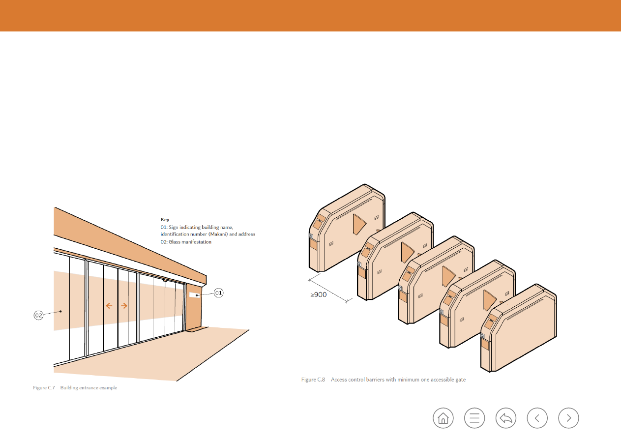
An example of an accessible building entrance is shown in Figure C.7.

C.5.4.3 

Access control barriers

Where access control barriers are required, a minimum of one gate shall have a width 

of 900 mm minimum in accordance with Figure C.8. 

Turnstiles shall not be provided for the accessible gate.
If the access control barrier is glazed, manifestations shall be provided on the glass 

surface in accordance with C.7.2.3.

Dubai Building Code

Part C: Accessibility

C 14

C.5.5 

Internal accessible routes 

The clear width of internal accessible routes should be obtained from Table C.3, 

allowing for all pedestrians in all directions of travel.

Route

Minimum width (mm)

Recommended width (mm)

Internal accessible route

1,000 (see Figure C.9)

1,200

Turning and change of direction

1,500 (see Figure C.2 and 

Figure C.10)

1,575 to accommodate varying 

types of wheelchairs

Table C.3  External accessible route widths

Access for wheelchair users shall be provided to all accessible rooms, spaces and 

elements. Wheelchair users shall be able to pass other people and, where necessary, 

turn through 180°. The minimum width of internal accessible routes shall be kept 

free of protruding objects such as doors, vegetation, furniture, equipment and signs.
Corridors in buildings shall conform to 

Part B

 and Ch. 3 of UAE FLSC 

[Ref. C.1]

 in 

addition to the accessible route minimum clear width requirements (see Figure C.10).

Dubai Building Code

Part C: Accessibility

C.5.6 

Minimum clearances

C.5.6.1 

Interaction space

Interaction spaces shall be provided in accessible spaces and:
a) shall not encroach upon the accessible route;
b) shall be frontal or to the side as required; and
c) where face to face interaction is intended, shall have a knee clearance in

accordance with C.5.6.2.

Interaction spaces shall conform to the dimensions in Table C.4. Examples of 

interaction spaces are shown in Figure C.11 and Figure C.12.

Dubai Building Code

Part C: Accessibility

C 16

When objects have the potential to encroach upon an interaction space, the 

interaction space should be marked with a carpet or painting as shown in Figure C.13. 

Examples of encroachment include shoes in a prayer room entrance and a paper bin 

in the side approach space to a toilet.

C.5.6.2 

Toe and knee clearance

Space for toe and knee clearance below an element shall be provided in accordance 

with the minimum dimensions shown in Table C.5 and Figure C.14.

Dubai Building Code

Part C: Accessibility

C 17

C.5.6.3 

Protruding objects

Objects lower than 2,100 mm above finished floor level (FFL) shall not protrude into 

the accessible route more than 100 mm. The minimum clear width of the accessible 

route shall also be maintained.
Where objects protrude more than 100 mm from façades, columns, walls, posts and 

building elements, the protruding edge shall extend to the floor or be a minimum of 

300 mm above the floor (see Figure C.15).

Where practical, vertical clearance shall be a minimum height of 2,100 mm. Any area 

with a vertical clearance of less than 2,100 mm shall be marked by a guardrail or 

barrier, as shown in Figure C.16. The leading edge of the guardrail or barrier shall be a 

minimum of 700 mm above the ground or FFL. 

Dubai Building Code

Part C: Accessibility

C 18

C.5.7 

Reach ranges

C.5.7.1 

Forward reach

C.5.7.1.1  Unobstructed forward reach

The range of unobstructed high and low forward reach shall be as shown in Table C.6 

and Figure C.17.

Condition – Unobstructed

Height (mm)

High forward reach

1,200 max.

Low forward reach

400 min.

Table C.6  Unobstructed forward reach

Figure C.17  Unobstructed forward reach (modified figure based on 2010 ADA Standards for Accessible Design, 

US Department of Justice 2010,  Figure 308.2.1.)

C.5.7.1.2  Obstructed forward reach

Where high forward reach is obstructed, clear floor space below the obstruction 

shall extend to a depth equal to or greater than the required reach depth over the 

obstruction. The range of high forward reach shall be as shown in Table C.7 and 

Figure C.18.

Condition – Obstructed

Reach depth (mm) (d)

Height (mm)

High forward reach (a)

500 max.

1,200 max.

High forward reach (b)

>500 up to 600 max.

1,100 max.

Table C.7  Obstructed forward reach

Figure C.18  Obstructed high forward reach (modified figure based on 2010 ADA Standards for Accessible 
Design, US Department of Justice 2010, Figure 308.2.2.)

Dubai Building Code

Part C: Accessibility

C 19

C.5.7.2 

Side reach

C.5.7.2.1  Unobstructed side reach

Where clear space allows a parallel approach to an element, the range of 

unobstructed high and low side reach shall be as shown in Table C.8 and  

Figure C.19. The depth of any obstruction between the clear floor or ground space 

and the element shall not exceed 250 mm.

Condition – Unobstructed

Height (mm)

High side reach

1,200 max.

Low side reach

400 min.

Table C.8  Unobstructed side reach

Figure C.19  Unobstructed side reach (modified figure based on 2010 ADA Standards for Accessible Design, US 
Department of Justice 2010, Figure 308.3.1.)

C.5.7.2.2  Obstructed side reach

Where clear space allows a parallel approach to an element, the high side reach over 

an obstruction shall be as shown in Table C.9 and Figure C.20.

Condition – 

Obstructed

Reach depth (mm) (d)

Height of obstruction 

(mm)

Height (mm)

High side reach (a)

250 max.

850 max.

1,200 max.

High side reach (b)

>250 up to 600 max.

850 max.

1,100 max.

Table C.9  Obstructed side reach

Figure C.20  Obstructed side reach (modified figure based on 2010 ADA Standards for Accessible Design, US 

Department of Justice 2010, Figure 308.3.2.)

Dubai Building Code

Part C: Accessibility

C 20

C.5.7.3 

Children’s reach ranges

Reach ranges for children in different age groups shall be as shown in Table C.10 and 

Figure C.21.

Forward or side reach

Reach ranges for ages 

3 and 4 (mm)

Reach ranges for ages 

5 through 8 (mm)

Reach ranges for ages 

9 through 12 (mm)

High (max.) (Y)

900 

1,000

1,100

Low (min.) (X)

500

450

400

Table C.10  Children's reach ranges

C.5.7.4 

Switches, controls and socket outlets 

Switches, controls and socket outlets shall be installed between 400 mm and  

1,200 mm above floor level (see Figure C.22). Controls requiring precise hand 

movement should be installed between 750 mm and 1,000 mm above floor level 

(see Figure C.22).

Switches and controls shall be located a minimum of 300 mm away from any corner 

(see Figure C.23).

Switch controls and socket outlets shall be installed in accordance with the reach 

ranges specified in C.5.7.1 and C.5.7.2.
Switch plates should have a minimum reflectance contrast of 30 points LRV 

compared to the surrounding wall.

It shall be possible to activate switches with an elbow or a closed fist as shown in 

Figure C.23.

Figure C.22 

Switch, control and  

socket outlet heights (© British Standards 

Institute. Figure extracted from BS 

8300:2018. Permission to reproduce 

extracts from British Standards is granted 

by BSI Standards Limited (BSI). No other 

use of this material is permitted).

Figure C.23 

Switch, control and socket  

outlet position at corners (© British Standards Institute. 

Figure extracted from BS 8300:2018. Permission to 

reproduce extracts from British Standards is granted by 

BSI Standards Limited (BSI). No other use of this material 

is permitted).

Dubai Building Code

Part C: Accessibility

C 21

C.5.8 

Accessible doors

C.5.8.1 

Minimum accessible door requirements

NOTE: Doors can be manually operated, or power-assisted. Automatic doors are 

preferred for high pedestrian traffic areas. 

The following requirements and recommendations apply to accessible doors.
a) Revolving gates, revolving doors and turnstiles shall not be part of an accessible

route. Where they are used for general circulation, adjacent accessible doors shall

be provided, and these shall be available for use at all times.

b) Where double-leaf doors and gates are provided, at least one active leaf shall have

a clear width of 915 mm. The active leaf shall conform to the requirements of this

subsection. Where the active leaf is in a bank of doors it shall be marked with the

symbol for people of determination.

c) Single doors, except toilet doors, shall have a minimum clear width of 915 mm,

measured between the face of the door and the face of the doorstop, with the

door open 90° (see Figure C.24).

d) The opening space of a door shall not encroach upon manoeuvring spaces and

accessible routes (see Figure C.10).

e)

Floor surfaces at doors should be levelled to the floor. When levelling is not

achievable, a raised threshold shall have a maximum height of 13 mm and be

bevelled down to a height of 6 mm chamfered (see Figure C.25). The threshold

shall have a maximum slope gradient of 50%.

f) The force required to open a door shall not exceed 25 N, unless the door is

automatic/power-assisted.

g) Swinging door leaves shall be able to open 90 °.

Dubai Building Code

Part C: Accessibility

C 22

C.5.8.2 

Hardware requirements

C.5.8.2.1  Door opening hardware

Means of opening and closing (such as door handles, pull handles and push plates) 

shall be placed at a height between 865 mm and 1,220 mm. They shall be easy to 

grasp and use. Pressure mechanisms or levers shall be automatic, or easy to operate 

with the elbow or a closed fist as shown in Figure C.26. 

Door levers and handles shall be separated from the door by a minimum of 40 mm 

(see Figure C.27 and Figure C.28).
To open sliding doors, a vertical fixed bar or pull handle shall be provided. The vertical 

bar or pull handle shall be installed between 865 mm and 1,220 mm above the floor 

(see Figure C.28).

Figure C.26  Lever mechanism operated by a closed fist

Round knobs and thumb latches shall not be used because they require tight grasping 

and finger control. Doors equipped with closers shall have a minimum closing time 


of 5 s.

In high pedestrian traffic areas (such as washrooms), minimum 250 mm high kick 

plates are recommended.

C.5.8.2.2  Vision panels

It is recommended that vision panels are provided for doors in entrance lobbies and 

high traffic areas. Vision panels should be a minimum of 100 mm wide and should be 

positioned vertically in the viewing range of wheelchair users (as described in C.7.1). 

The provision of vision panels in fire doors shall conform to Ch. 1 and Ch. 3 of UAE 

FLSC 

[Ref. C.1]

. The guidance given in BS 8300 for door hardware, access control 

systems and vision panels should be followed.

Dubai Building Code

Part C: Accessibility

C 23

C.5.8.3 

Manoeuvring spaces at manual doors and doorways without doors

C.5.8.3.1  Manoeuvring spaces for swinging and sliding doors

Doors on accessible routes shall have a clear manoeuvring space on both sides. The 

manoeuvring space shall be free of obstacles and no other swinging doors shall open 

into it. 
Manoeuvring spaces shall be designed with the dimensions shown in Table C.11.

Door type

Minimum clear floor 

space (mm)

Minimum space 

adjacent to leading 

edge of door (mm)

Swing – Front approach, pull side (Figure C.29)

1,500 wide

450 to 600

Swing – Front approach, push side (Figure C.29)

1,200 wide

300

Swing – Side approach, hinge pull side (Figure C.30)

1,500 wide

900

Swing – Side approach, hinge push side (Figure C.30)

1,050 wide

600

Swing – Side approach, latch pull side (Figure C.31)

1,200 wide

600

Swing – Side approach, latch push side (Figure C.31)

1,050 wide

600

Sliding – Both sides (Figure C.32)

1,200 wide

300

Table C.11  Door manoeuvring

Figure C.29  Manoeuvring for swinging doors – Front approach

Key

01: Pull side

02: Minimum clear area

03: Push side

Dubai Building Code

Part C: Accessibility

C 24

Figure C.30  Manoeuvring for swinging doors – Side approach – Hinge side

Key

01: Minimum clear area

Figure C.31  Manoeuvring for swinging doors – Side approach – Latch side

Key

01: Minimum clear area

Figure C.32 

Manoeuvring for sliding doors 

– Front approach

Key

01: Minimum clear area

02: Sliding door


Content      ..     5      6      7      8     ..