Maserati Ghibli (2018 year). Manual in english - page 3
Driving
NOTE:
NOTE:
Normal starting of either a cold or a
If the ignition switch is left in the ACC
warm engine is obtained without
or RUN (engine not running) position
pumping or pressing the accelerator
and the transmission is in P (Park), the
pedal.
system will automatically time out
after 30 minutes of inactivity and the
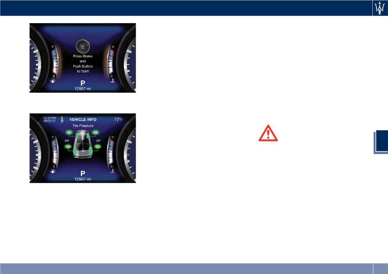
If the driver only pushes the
ignition will switch to the OFF
START/STOP button but does not press
position.
the brake pedal, the ignition switch
cycles to the ACC position (see “Keys”
After starting the engine, the idle
in section “Before Starting”) and the
speed is controlled automatically and
The current display subsequently sets
instrument cluster displays the latest
will decrease as the engine warms up.
up with the latest screenshot.
screenshot.
Engine Start Failure
At the second press of the
START/STOP button, the ignition
device switches to RUN position (see
“Keys” in section “Before Starting”)
WARNING!
5
and the instrument cluster displays the
• Do not attempt to push or tow your
latest screenshot.
vehicle to get it started. Vehicles
At the third press of the START/STOP
equipped with an automatic
button the ignition switch returns to
transmission cannot be started this
OFF position and the display powers
way.
down.
• If the vehicle battery is dead,
If the engine fails to start, the starter
At the fourth press of the START/STOP
booster cables may be used to
will disengage automatically after 10
button the screen will display the
obtain a start from a booster battery
seconds. If you wish to stop the
message that invites you to press the
or the battery in another vehicle.
cranking of the engine prior to
brake pedal and push the START/STOP
This type of start can be dangerous
starting it, press the button again.
button to start the engine.
if done improperly. See “Auxiliary
Jump Start Procedure” in section “In
an Emergency” for further
information.
203
Driving
Starting with a Cold Engine
NOTE:
Automatic Start&Stop System
Start-off slowly, avoiding sudden
If the ignition switch is left in the ACC
The Maserati Start&Stop system allows
acceleration and rev the engine up at
or RUN (engine not running) position
the engine to automatically switch off
low medium speeds. High-
and the transmission is in P (Park), the
when the vehicle stops and to restart
performance driving should be
system will automatically time out
when the driver intends to drive. This
avoided until the engine temperature
after 30 minutes of inactivity and the
feature helps reduce fuel
reaches 149-158°F (65-70°C).
ignition will switch to OFF position.
consumption. During the “Stop
Engine Turn-Off
(AutoStop)” phase the ignition is still
Engine Turn Off when in Automatic
on and all security features are
• With the shift lever in P (Park), D
Start&Stop
available.
(Drive) or R (Reverse) positions (see
When the engine has been turned off
In order for the Start&Stop to activate,
“Automatic Transmission” in this
by the Start&Stop system, press and
the vehicle must be stationary and the
section) and vehicle standstill, press
release the START/STOP button. The
brake pedal adequately pressed.
and release the START/STOP button
ignition switch will return to the OFF
to switch off the engine. A burst on
position and the vehicle is off.
NOTE:
the accelerator pedal before turning
If the brake pedal is not sufficiently
off the engine has no purpose and
“Panic Stop” Strategy
5
pressed the Start&Stop may not
increases fuel consumption.
In panic conditions, if driver stops
function even if the vehicle is stopped.
• If the shift lever is in N (Neutral) and
engine in any non-standard manner
When the Start&Stop switches off the
the START/STOP button is pressed
while driving at a speed over 2 mph
engine, the related light
once, the instrument cluster will
(3 km/h), the “Panic Stop” strategy can
illuminates on the instrument
display a “Vehicle Not in Park”
manage the situation by checking
cluster.
message and the engine will remain
gearchange condition upon engine
As soon as the brake pedal is released,
running.
cutting, driver’s action on brakes, road
the engine turns on.
condition (flat or slope) so as to set
While the vehicle is stopped, the shift
gearchange to the most suitable
lever can be placed in P (Park).
condition.
WARNING!
In this case it is possible to release the
The “Panic Stop” strategy considers
Never leave a vehicle out of the P
brake pedal and the vehicle will
that the driver should stop the engine
(Park) position, as it could move.
remain in “AutoStop” with engine off.
by pressing the ignition switch at least
Pressing the brake pedal and shifting
3 times or holding it depressed for at
gear into D (Drive) or R (Reverse) will
least 2 seconds.
204
Driving
deactivate the “AutoStop” condition
Start&Stop Not Active
• When the front and rear “defroster”
and restart the engine.
function is activated.
For keeping driving safety, interior
comfort and a correct functioning of
• When the engine coolant and the
engine and vehicle, the Start&Stop
engine oil temperature are not on
function does not activate under the
proper functioning level.
following conditions:
• When the external temperature is
too cold.
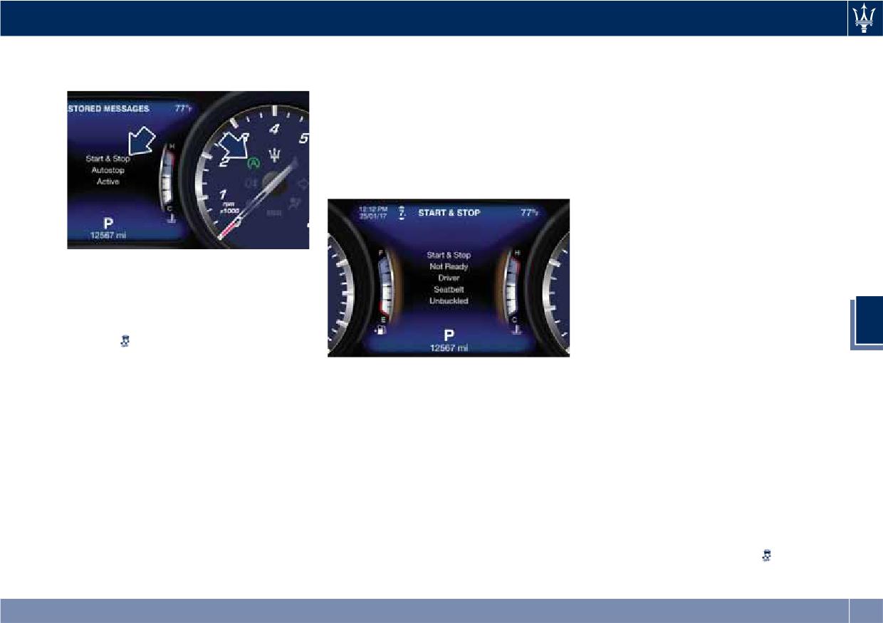
• When the driver’s seat belt is
unbuckled (see example).
• When the battery charge is below
safety value.
• When the previous stop had just
happened (few seconds) and the
minimum speed has not yet been
Start&Stop Deactivated
achieved.
Start&Stop function is deactivated
• Shortly after R (Reverse) has been set
under the following conditions:
or when driving under a certain
speed level.
• When SPORT drive mode is activated.
5
• When the hood is open.
• When
(ESC OFF) drive mode is
activated.
• The sensors managing the
• When the driver door is open.
Start&Stop have been damaged.
• If it has been disabled through the
main menu item “Start & Stop” via
• When the fuel level is too low.
• Start&Stop system faults are present.
the controls on the right side of the
• When the vehicle is stopped on a
• When Adaptive Cruise Control (ACC)
steering wheel (see chapter
very steep road.
and/or Highway Assist (HAS) system
“Instrument cluster” in section
• When the vehicle is stopped with
are engaged.
“Dashboard Instruments and
steered wheels (over 135° of steering
Automatic Restarting of the Engine
Controls”) or via the MTC+ in the
wheel angle for each part).
The engine may automatically restart,
“Controls” page (see “MTC+
• When the vehicle is manoeuvring:
before the brake pedal has been
"Controls" Screen” in section
shift lever in R (Reverse).
released, when one of the following
“Dashboard Instruments and
• When the temperature conditions
conditions occurs:
Controls”).
inside the vehicle do not correspond
• The SPORT drive mode or
drive
to the air conditioning setting.
mode is being activated.
205
Driving
• If the Start&Stop function has been
• The driver unbuckles his/her seat belt
and the vehicle’s surrounding area.
disabled through the main menu
and releases the brake pedal.
Never leave the vehicle unattended
voice “Vehicle Settings” (see chapter
• The driver opens the door and
with the engine running; doing so
“Instrument cluster” in section
releases the brake pedal.
poses a risk of danger. It is a good
“Dashboard Instruments and
practice to always ensure to set the
• The driver unbuckles the seat belt
Controls”).
parking brake and place the
and opens the door.
• If shift lever is moved to R (Reverse).
transmission gear selector lever into
• The driver opens the hood.
the P (Park) position, thereby
• If the steering wheel is moved to
All the above-mentioned conditions
ensuring the vehicle will not move,
steer the wheels.
deactivate the Start&Stop function
when performing any vehicle checks,
• When the temperature conditions
(the “AutoStart” is deactivated and
maintenance and/or service
inside the vehicle do not correspond
the engine remains off) and the shift
procedures on the vehicle.
to the air conditioning setting.
lever moves automatically in P (Park).
• When changing the temperature
The
telltale will flash to indicate
Start&Stop Function Disabling
setting on the air conditioning.
the Start&Stop function disabling. To
Under certain driving conditions, when
restart the engine it is necessary to
• When the defroster function is being
frequent stops and restarts of the
press the brake pedal and push the
activated.
5
engine may become annoying, it is
START/STOP button.
• When the battery charge is below
possible to disable the Start & Stop
Move the shift lever to D (Drive) to
safety value.
function.
drive away.
• When the accelerator pedal is being
Use the controls located on the right
pressed (together with the brake
side of the steering wheel (see
pedal).
instructions in chapter “Instrument
WARNING!
• If a long time has passed since the
Cluster” in section “Dashboard
• Even when the vehicle is stopped in
last automatic stop of the engine.
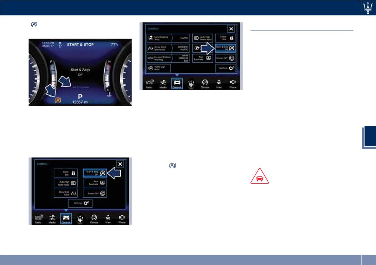
Instruments and Controls”) and select
the “Stop (AutoStop)” phase, the
“Start & Stop” main menu item which
Occupants Safety Function
driver is responsible for the vehicle
displays the status of the function:
and the occupants and shall take
To enhance occupants safety, the
Start & Stop enabled is the default
care of what happens inside and
Start&Stop system monitors if the
status.
outside the vehicle.
driver is present and does not allow
Hold the switch (►) to change the
automatic restarting of the engine if
• Even when the vehicle is stopped
status of the function.
one of the following maneuvers is
within the “Stop (AutoStop)” phase,
When the Start&Stop function is
being performed while in “AutoStop”
the vehicle driver is responsible for
disabled, in addition to the related
condition:
the vehicle, the vehicle’s occupants
message the amber indicator
206
Driving
indicated in the picture will turn
Automatic Transmission
on.
The electronic shift lever replaces the
conventional mechanical lever and has
no mechanical connection to the
transmission. The transmission is
operated by electrical actuators on the
hydraulic system and all commands to
the control system are transmitted by
the CAN network. The lever itself
represents a mere user interface. Gear
With ADAS
positions are simulated by solenoids
• Touch a second time the same
inside the lever body, which are
soft-key to re-enable the function.
Another way to disable the Start &
computer-controlled and enable or
Stop is via the MTC+.
NOTE:
disable certain positions of the lever.
• Touch the “Controls” soft-key on the
The highlighted soft-key indicates the
The solenoids inside the shift lever
lower part of MTC+ display.
prevent the movement of the lever
disabled status of Start & Stop system
5
towards invalid positions.
• Touch the “Start & Stop Off”
and vice versa.
The electronically-controlled
soft-key to disable the function.
Start&Stop System Failure
transmission provides a precise shift
schedule.
When the
indicator light and the
related message illuminate on the TFT
display (see chapter “Instrument
CAUTION!
Cluster” in section “Dashboard
In order to properly use the automatic
Instruments and Controls”) there is a
transmission, it is essential that you
malfunction in the Start&Stop system
read through the whole chapter, so
and the engine cannot be switched off
that you can understand right from
and restarted automatically. To switch
the start what the correct and
off or restart the engine it is necessary
permitted operations are.
to push the START/STOP. Have the
Without ADAS
Damage to the transmission may occur
vehicle checked at an Authorized
Maserati Dealer.
(Continued)
207
Driving
(Continued)
is running. Before exiting a vehicle,
• N (Neutral);
if the following precautions are not
always apply the electronic parking
• D (Drive) automatic forward speed (8
observed:
brake, shift the transmission into P
speeds);
(Park), and turn the engine off.
• Shift into P (Park) only after the
• -/+ to downshift or upshift when
vehicle has come to a complete stop.
• When leaving the vehicle, always
manual mode in D (Drive) status, or
This is the default position of the
remove the key fob and lock your
set to M (Manual) mode (see “Drive
lever and should be used every time
vehicle.
Mode” in this section).
the ignition switch is cycled to OFF.
• Do not leave the key fob in or near
• Shift into or out of R (Reverse) only
the vehicle.
after the vehicle has come to a
This vehicle is equipped with a feature
complete stop and the engine is at
which requires the shift lever to be
idle speed.
placed in P (Park) before the engine
• Do not shift between P (Park), R
can be turned off. This prevents the
(Reverse), N (Neutral) or D (Drive)
driver from inadvertently leaving the
when the engine is above idle speed
vehicle without having placed the
• To effect any change from vehicle
transmission in P (Park). This system
5
stop to R (Reverse), D (Drive), 1st or
also locks the shift lever in P (Park)
2nd gear, it is necessary to keep the
whenever the ignition switch is in the
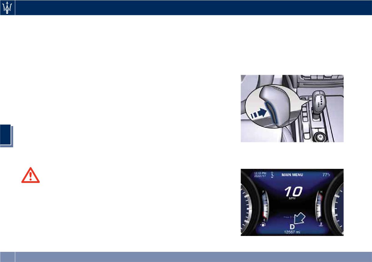
Transmission status is visible on the
brake pedal fully depressed.
OFF position.
lever and on the lower part of the
Instrument cluster display.
Automatic Transmission Lever
Automatic transmission is operated by
WARNING!
a selection lever with unlock button
• It is dangerous to move the shift
located on the central console.
lever out of P (Park) or N (Neutral) if
By using the selection lever it is
the engine speed is higher than idle
possible to select the following
speed. Only shift into gear when the
positions, indicated on the top of the
engine is idling normally and when
lever: the selected position will
your foot is firmly pressing on the
illuminate in white light.
brake pedal.
• P (Park);
• As with all vehicles, you should
• R (Reverse);
never exit a vehicle while the engine
208
Driving
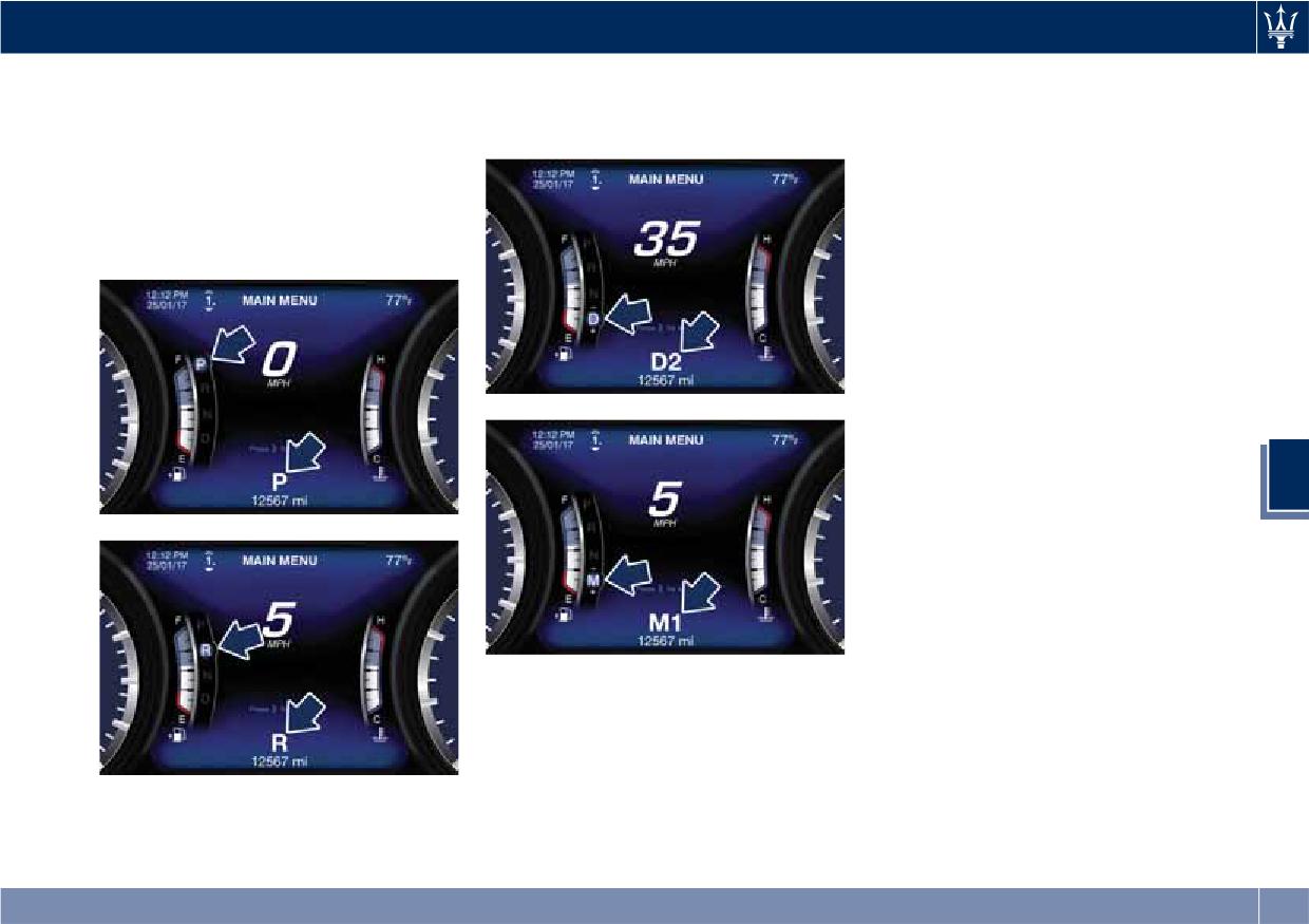
By pressing the release button on the
position is indicated beside the lever
You must also press the brake pedal to
lever, the gear position field is
status, on the lower part of the
shift the transmission out of P (Park)
displayed: if you release the button
display.
position.
without moving the lever, the field
Shifting from D (Drive) to P (Park) or R
disappears after 2 seconds. By
(Reverse) should be done only after
operating instead the lever, the new
the accelerator pedal is released and
range will be indicated in the field
the vehicle is stopped. Be sure to keep
and in the lower part of the display.
your foot pressed on the brake pedal
when moving the shift lever between
these gears.
DO NOT race the engine when shifting
from P (Park) or N (Neutral) into
another gear range.
Automatic Transmission Range
P (Park)
Use this position to park the vehicle.
5
The transmission can be shifted from P
(Park) position only with the brake
pedal pressed. To move the shift lever
from P (Park) position to any other
position, the engine must be switched
on. The engine can be regularly
started in P (Park) range. Never
In normal conditions, the shift lever is
attempt to use P (Park) while the
always unlocked. When in D (Drive)
vehicle is in motion. When parking on
mode it is possible to upshift or
a level surface, you may place the shift
downshift the changing gears by
lever in the P (Park) position first, and
automatically temporarily setting in M
then apply the electronic parking
If the vehicle is temporarily in the
(Manual) mode.
brake by pulling the trigger upwards.
manual drive mode, D (Drive) status,
or in M (Manual) drive mode, the gear
209
Driving
R (Reverse)
This range is used to move the vehicle
WARNING!
backward.
• Never use the P (Park) position as a
We recommend to shift into R
substitute for the electronic parking
(Reverse) only after the vehicle has
brake. Always apply the parking
come to a complete stop.
brake fully when parked to prevent
vehicle movement and possible
• Vehicle halted: switching between P
injury or damage.
(Park), R (Reverse) and D (Drive)
requires pressing the unlock button
• Make sure the transmission is in P
on the lever and brake pedal: N
(Park) before leaving the vehicle.
The Instrument cluster will display the
(Neutral) is reached only by pressing
related indicator light
and the
the unlock button on the lever.
message for 5 seconds.
• Vehicle moving: the driver can switch
CAUTION!
from R (Reverse) to N (Neutral), or
• DO NOT race the engine when
vice versa, by pressing the unlock
shifting from P (Park) or N (Neutral)
button on the shift lever.
5
into another gear range, as this can
damage the drivetrain.
N (Neutral)
• The following indicators should be
• Vehicle halted and engine started:
used to ensure that you have
switching from N (Neutral) to R
engaged the shift lever into the P
(Reverse), P (Park) and/or D (Drive)
(Park) position:
requires brake pedal and unlock
- when shifting into P (Park), press
button pressed.
the unlock button on the shift
• Vehicle moving: switching from N
When parking on a hill, apply the
lever and push the lever all the
(Neutral) to R (Reverse) and/or D
parking brake before placing the shift
way forward until it stops.
(Drive) requires pressing the unlock
lever in P (Park).
- with the brake pedal released,
button. Switching to R (Reverse)
For enhanced security, turn the front
verify that P (Park) position is
starting from N (Neutral) is only
wheels toward the kerb on a downhill
illuminated on the shift lever.
possible if the vehicle is moving
and away from the kerb on an uphill
backwards, while switching to D
grade.
(Drive) starting from N (Neutral) is
210
Driving
only possible if the vehicle is moving
driving characteristics under all normal
the system to enter a temporary
forwards.
operating conditions of the vehicle.
function and enable the manual
Set the parking brake and shift the
shift mode. This range is indicated
• Vehicle stationary: switching from D
transmission into P (Park) if you must
with the symbols “-/+” on the left
(Drive) to R (Reverse) and/or to P
leave the vehicle.
and right sides of the “D” letter on
(Park) requires brake pedal and
the gear range field of the display.
unlock button pressed: reaching N
The system will then switch back to
(Neutral) starting from D (Drive) is
automatic mode according to time
WARNING!
allowed by only pressing the unlock
elapsed in “temporary” mode and
Do not switch to N (Neutral) and/or
button on the shift lever.
driving conditions.
never turn off the ignition to coast
• To enable special operations while
At extremely cold temperatures
downhill. These are unsafe practices
the car is moving at a low speed,
(-23°F/-30°C or below), transmission
that limit driver’s response to
such as getting out of marsh or
may be affected by the low
changing traffic or road conditions.
snow, it is possible to run quickly
temperature of the engine and
from D (Drive) to R (Reverse), and
transmission. Normal operation will
vice versa, by pressing the reset
resume once the transmission
CAUTION!
button on the gear shift lever.
temperature has risen to a normal
5
Towing the vehicle, coasting, or
• Vehicle moving: switching to N
level.
driving for any other reason with the
(Neutral) from D (Drive) requires the
transmission in N (Neutral) can result
unlock button on the shift lever
Transmission Malfunction and
in transmission damage. Refer to
pressed.
Overheating Conditions
“Towing a Disabled Vehicle” in section
• From D (Drive) selected mode it is
Transmission Emergency Control
6 for further information.
always possible to switch to M
Transmission function is electronically
(Manual), by pressing the M
monitored to detect abnormal
D (Drive)
(Manual) button: the Led indicator
conditions. If a condition that could
This range should be used for most
beside the button will light up; to
result in transmission damage is
city and highway driving. It provides
return to D (Drive) position, the
detected, Transmission Limp Home
the smoothest upshifts and downshifts
same action should be performed as
Mode will be activated. In this
and the best fuel economy. The
the LED will turn off.
situation, the transmission may
transmission automatically shifts up
• When in D (Drive) mode, moving the
operate only in certain gears, or may
and down through all gears. The D
shift lever forward or backwards to
not shift at all. In some situations, the
(Drive) position provides optimum
the next step without pressing the
transmission system may not
unlock button on the lever will cause
211
Driving
re-engage if the engine is turned off
driving without demanding high
NOTE:
and restarted.
engine performance. If the red
Even if the transmission can be reset,
A message in the instrument cluster
warning light
and the related
we recommend that you visit an
will inform the driver about the more
message turns on again, it is advisable
Authorized Maserati Dealer at your
serious transmission conditions, and
to stop the vehicle, turn off the engine
earliest possible convenience, which
indicate what actions may be
and wait for the engine/transmission
has diagnostic equipment to
necessary.
assembly to fully cool down.
determine if the problem could recur.
If the instrument cluster message
Transmission Oil Overtemperature
indicates that the transmission may
Transmission Manual Release of
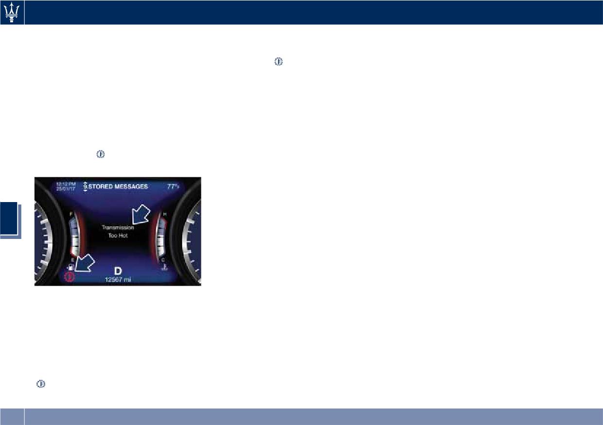
If the transmission oil temperature
not re-engage after engine shutdown,
P (Park) Position
exceeds the operating limit, the red
perform the following procedure
See chapter “Transmission Manual
warning light
illuminates on the
preferably at an Authorized Maserati
Release of P (Park) Position” in section
instrument cluster.
Dealer.
“In an Emergency”.
In the event of a momentary problem,
the transmission can be reset to regain
all forward gears by performing the
following steps.
5
• Stop the vehicle.
• Shift the transmission into P (Park), if
possible.
• Turn the engine off.
• Wait approximately 30 seconds.
In this case, slow down until
• Restart the engine.
temperature returns to normal level
• Shift the transmission into D (Drive)
(the light will turn off).
and then into the desired gear
If this is not sufficient, we recommend
range. If the problem is no longer
to stop the vehicle, shift the lever to
detected, the transmission will return
position P (Park) or N (Neutral) and
to normal operation.
keep the engine idle until the
temperature red warning light
turns off and the message
disappears from the display. Resume
212
Driving
All-Wheel Drive (AWD
version only)
WARNING!
There may be a slight delay for AWD
The active on-demand All-Wheel Drive
engagement after a wheel slip
(AWD) system provides available
condition occurs.
optimum traction for a wide variety of
road surface and driving conditions.
The system minimizes wheel slip by
automatically redirecting torque to
the front and rear wheels as necessary.
To maximise fuel economy, the AWD
system automatically disangages
torque distribution on front axle when
road and environmental conditions
are such that wheel slip is unlikely to
occur. When specific road and
environmental conditions require
5
increased levels of road traction, the
NOTE:
AWD system automatically distributes
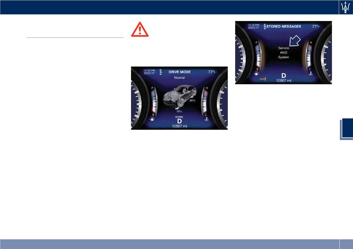
If the AWD system service warning
the torque between front and rear
light and message appears after
axle in order to grant the best driving
engine start up, or during driving, it
experience. Torque distribution is
means that the AWD system is not
displayed on the TFT in the “Drive
functioning properly. If the warning
Mode” main menu. Refer to
light and message are often activated,
paragraph “TFT Display: Menus and
it is recommended to have the vehicle
Settings” in chapter “Instrument
serviced at an Authorized Maserati
Cluster” of section “Dashboard
Dealer.
Instruments and Controls” for further
information.
213
Driving
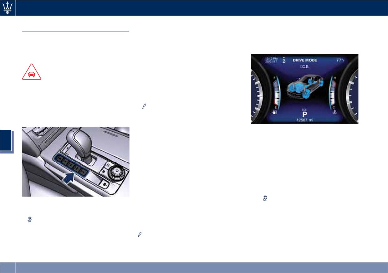
• I.C.E: to activate/deactivate the drive
“On” (see example in the figure).
Drive Mode
mode to ensure increased control on
Refer to chapter “Instrument Cluster”
Controls Preview
slippery surfaces as well as higher
in section “Dashboard Instruments and
energy efficiency.
Controls” for further information.
Drive modes can be set using the
• SPORT: to activate/deactivate a
buttons on central console.
sportier drive mode. In this mode,
the vehicle has a faster throttle
CAUTION!
response and ESC sport calibration
“Normal” is the default drive mode,
(not recommended on wet/slippery
optimized for the best balance
surfaces). Activating this drive mode,
between performance, fuel
will also change the EPS setting.
consumption and emissions in the
•
(Suspension): to switch between
standard conditions use of the car.
the two Sport suspensions setting
modes: Sport-Normal (S, LED light
off) and Sport-Firm (H, LED light on)
Setting the Drive Mode
(for versions/markets where
5
provided). Activating this drive
Drive modes can be set using the
mode, will also change the EPS
buttons on central console.
setting.
Keys (buttons) only have two statuses:
By selecting one of these drive modes,
OFF and ON. The OFF status (button
the LED beside the button illuminates
released) is the standard function
and the vehicle configuration obtained
mode. The ON status is activated by
is graphically displayed on instrument
pressing the button, the dedicated LED
cluster. The same screen is also
will illuminate. It is necessary to press
obtained when selecting the “Drive
the
(ESC OFF) button for at least 3
Buttons on the central console have
mode” menu using the buttons on
seconds.
following functions:
steering wheel.
•
(ESC OFF): to disable/reactivate
When changing the drive mode
the ESC system.
between NORMAL, I.C.E., SPORT and
• M (Manual): to switch from
(Suspensions), engine temperature
automatic to manual drive mode.
and fuel level indicators inner edge
will change color if “Outline Coloring”
of submenu “Screen Setup” is set to
214
Driving
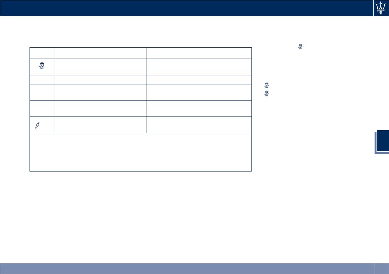
The table shows the different drive
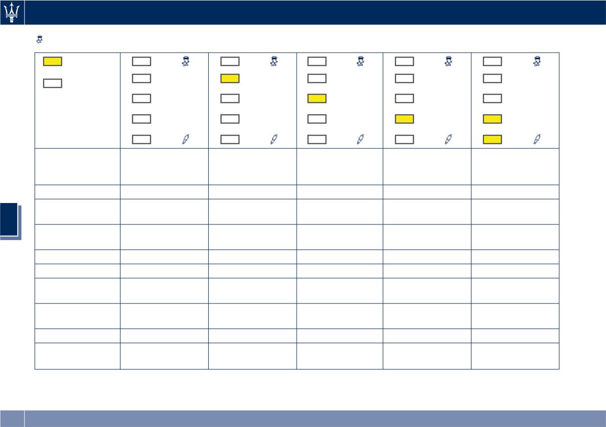
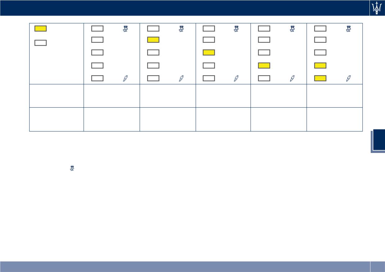
The tables below summarise the
modes according to the status of the
adjustment of transmission and
buttons.
engine parameters according to set
drive mode/s.
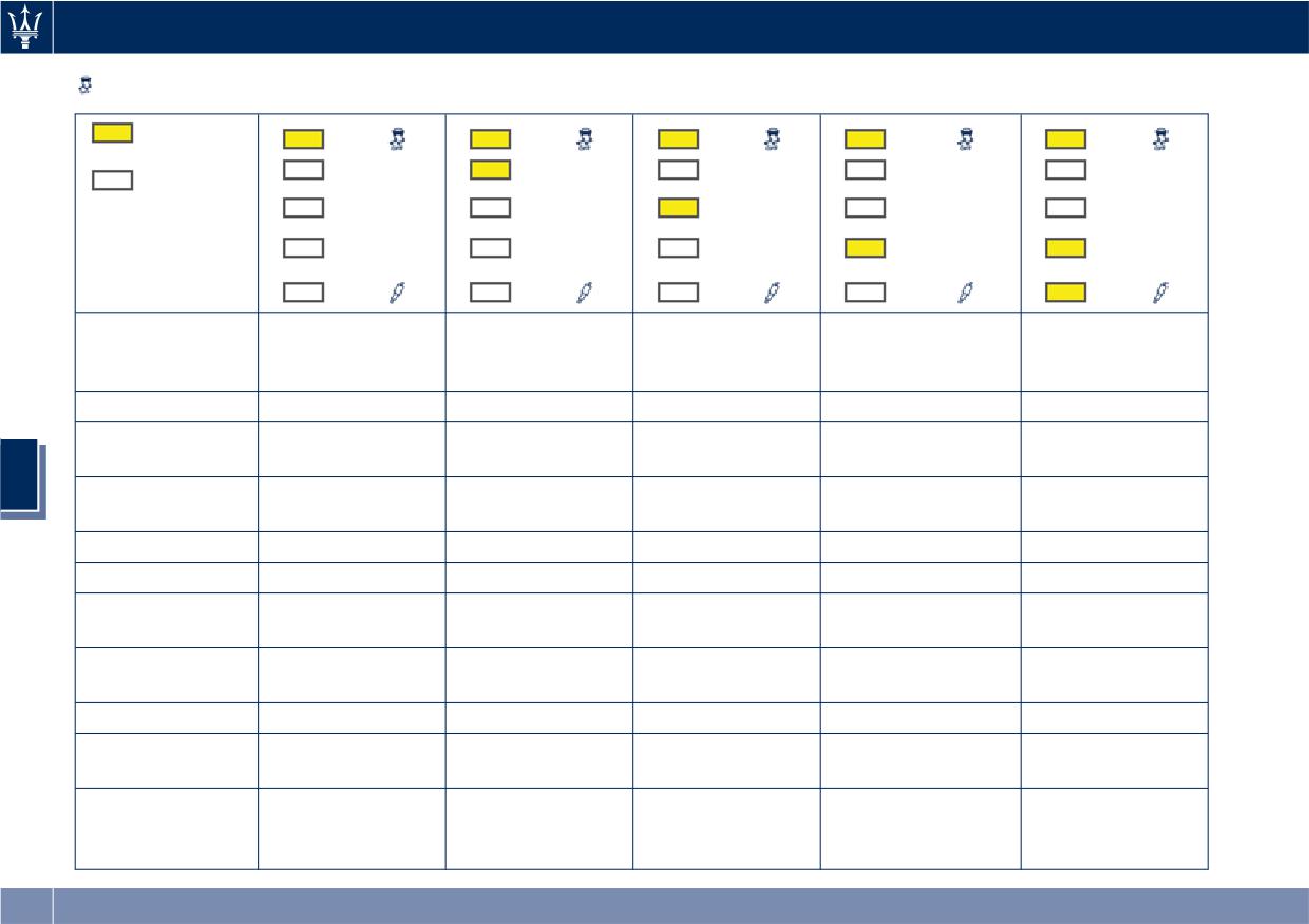
(ESC OFF) is the only
Button
OFF - Button released
ON - Button pressed (LED ON)
mode that does not depend on the
Electronic Stability Control ESC
Electronic Stability Control ESC
activation or deactivation of the other
activated.
partially deactivated.
modes. The tables show the two
configurations with:
M
Autoshift Mode (Auto).
Manual shift mode (Manual) ON.
•
(ESC OFF) button NOT pressed;
I.C.E.
Increased Control and
Increased Control and Efficiency
Efficiency mode OFF.
mode ON (**).
•
(ESC OFF) button pressed.
SPORT
Normal drive mode (NORMAL)
Sportier drive mode (SPORT) ON.
ON.
Sport-Normal suspensions
Sport-Firm suspension setting (S).
(*)
setting.
(*) Only with optional Skyhook active suspensions.
5
(**) I.C.E. (Increased Control and Efficiency) operates on engine supply in order
to reduce fuel consumption, exhausts, noisiness (efficiency) by dampening
vehicle reactions (control). The current mode is also useful for low-grip
surfaces.
215
Driving
(ESC OFF) Button NOT pressed
Button
pressed: LED ON
M
M
M
M
M
Button not
pressed: LED
I.C.E.
I.C.E.
I.C.E.
I.C.E.
I.C.E.
OFF
SPORT
SPORT
SPORT
SPORT
SPORT
Setup
Normal +
Normal + Auto +
I.C.E. + Auto +
Sport + Auto +
Sport + Auto +
Manual + Soft
Soft suspensions
Soft suspensions
Soft suspensions
Hard suspensions
suspensions
Stability control
Active
Active
Active
Active-Sport (*)
Active-Sport (*)
Electric Power
Normal
Normal
Normal
Sport
Sport
Steering (EPS)
5
Suspensions
Normal
Normal
Normal
Sport-Normal
Sport-Firm
setup
Engine control
Normal
Normal
Comfort
Performance
Performance
Engine boost
Normal boost
Overboost
Low boost
Overboost
Overboost
Low (Rev.
Low (Rev.
Exhaust sound
Low
Always High
Always High
Threshold)
Threshold)
Gear shifting
Normal
-
Comfort
Performance
Performance
point
Kick down
Yes
Yes
Yes - Soft
Yes - Strong
Yes - Strong
Upshift rev.
Yes (No, when in
Yes (No, when in
Yes
Yes
Yes
limiter
M)
M)
216
Driving
Button
pressed: LED ON
M
M
M
M
M
Button not
pressed: LED
I.C.E.
I.C.E.
I.C.E.
I.C.E.
I.C.E.
OFF
SPORT
SPORT
SPORT
SPORT
SPORT
Performance
Performance
Automatic
Normal
Anti - Stall
Comfort
(Anti - Stall,
(Anti - Stall,
downshift
when in M)
when in M)
Sport (Rapid -
Sport (Rapid -
Shifting timing
Normal
Rapid - Normal
Comfort
Sport, when in
Sport, when in
M)
M)
(*) In low- and medium-grip
5
conditions (e.g., rain, snow, ice, sand,
etc.) it is advisable not to activate
Sport mode, even with the ESC system
active (button
(ESC OFF) not
pressed).
217
Driving
(ESC OFF) Button pressed
Button
pressed: LED ON
M
M
M
M
M
Button not
pressed: LED OFF
I.C.E.
I.C.E.
I.C.E.
I.C.E.
I.C.E.
SPORT
SPORT
SPORT
SPORT
SPORT
Setup
Normal +
Normal + Auto +
I.C.E. + Auto +
Sport + Auto +
Sport + Auto +
Manual + Soft
Soft suspensions
Soft suspensions
Soft suspensions
Hard suspensions
suspensions
Stability control
OFF
OFF
OFF
OFF
OFF
Electric Power
Normal
Normal
Normal
Sport
Sport
Steering (EPS)
5
Suspensions
Normal
Normal
Normal
Sport-Normal
Sport-Firm
setup
Engine control
Normal
Normal
Comfort
Performance
Performance
Engine boost
Normal boost
Overboost
Low boost
Overboost
Overboost
Low (Rev.
Low (Rev.
Exhaust sound
Low
Always High
Always High
Threshold)
Threshold)
Gear
Normal
-
Comfort
Performance
Performance
shifting point
Kick down
Yes
Yes
Yes - Soft
Yes - Strong
Yes - Strong
Upshift rev.
Yes (No, when in
Yes (No, when in
Yes
Yes
Yes
limiter
M)
M)
Performance
Automatic
Performance (Anti
Normal
Anti - Stall
Comfort
(Anti - Stall,
downshift
- Stall, when in M)
when in M)
218
Driving
Button
pressed: LED ON
M
M
M
M
M
Button not
pressed: LED OFF
I.C.E.
I.C.E.
I.C.E.
I.C.E.
I.C.E.
SPORT
SPORT
SPORT
SPORT
SPORT
Sport (Rapid -
Sport (Rapid -
Shifting timing
Normal
Rapid - Normal
Comfort
Sport, when in
Sport, when in M)
M)
NOTE:
A different drive mode can be set even
with engine running and vehicle in
motion.
5
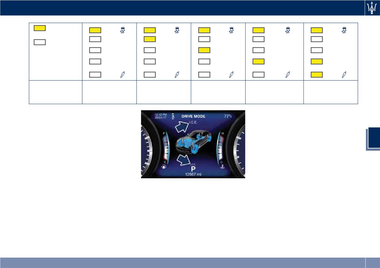
To activate a drive mode, press briefly
the corresponding button. The LED
beside the button will light up and set
drive mode screen will be displayed
(example in the figure: I.C.E.) for 5
seconds.
219
Driving
Activate/Deactivate
(ESC OFF) Drive
Mode
To activate
(ESC OFF) drive mode
press the corresponding button for at
least 3 seconds.
To disable the drive mode activated,
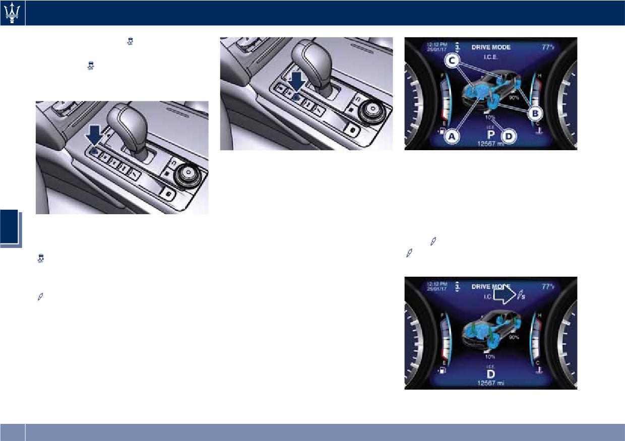
A Powertrain
press the same button again: the LED
B ESC
will turn off.
C Suspension stiffness
Monitoring Settings on Display
D Torque distribution (AWD version
By gaining access to “Drive mode”
To deactivate the drive mode, press
menu through the buttons on steering
only)
5
the same button again: the display will
wheel right-hand side, it is possible to
Press
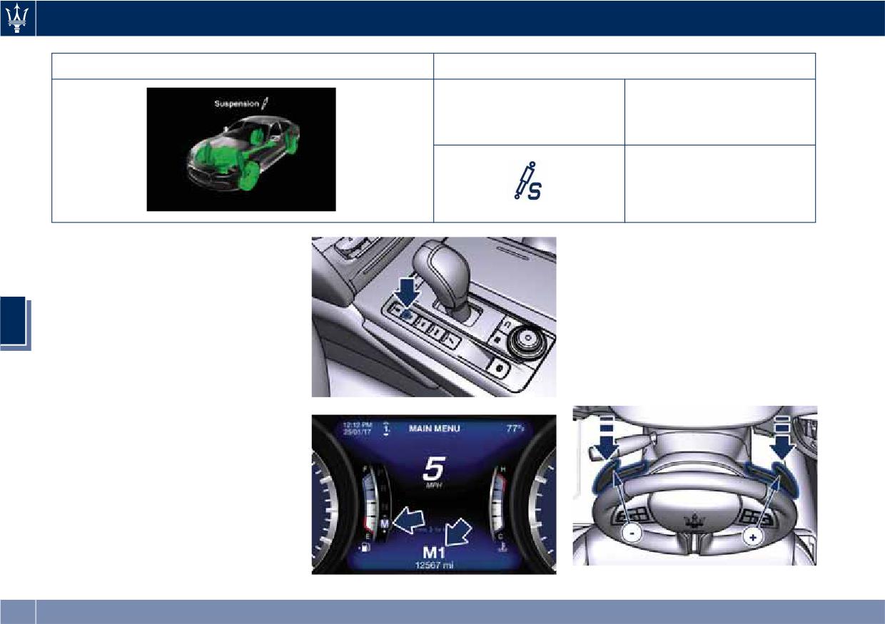
(Suspension) button, the
show the message indicating that
monitor the settings for driving.
icon with "S" beside will light up on
(ESC OFF) drive mode is off and ESC
The list and figure show vehicle
the upper right side of the TFT display.
system is active.
parameters referred to each drive
mode. Driving mode and its
Activate/Deactivate I.C.E., SPORT and
(Suspension) Drive Mode
parameters are identified by a
different color (example in the figure:
To activate one of this drive mode,
I.C.E.).
press the corresponding button once:
the LED above the symbol will turn on.
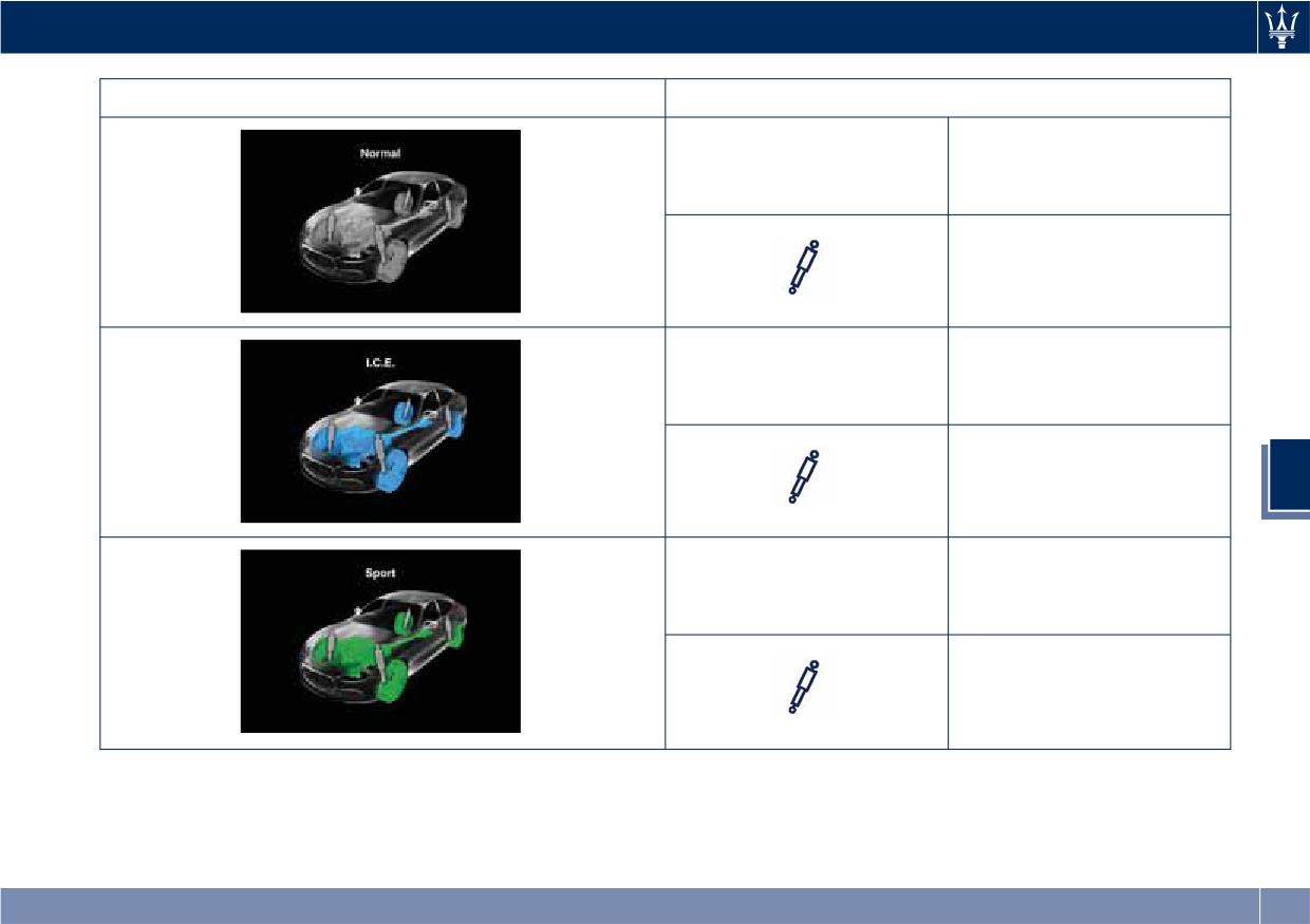
The table below specifies the default
setting for each drive mode.
220
Driving
Drive Mode
Default Condition
ESC
Normal
Normal
ESC
I.C.E.
Normal
5
ESC
Sport
Sport-Normal
221
Driving
Drive Mode
Default Condition
ESC
Sport
Sport-Firm
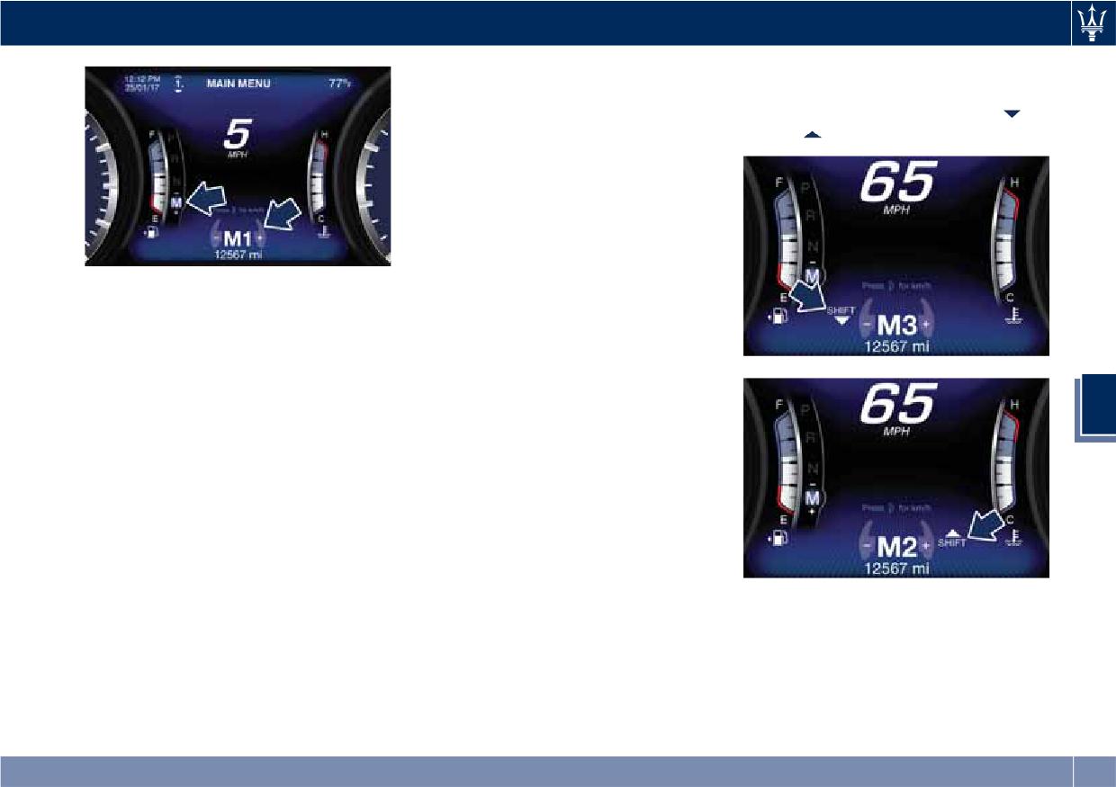
M (Manual) Drive Mode
Using the shift paddles behind the
steering wheel (if equipped), the
In this mode, the transmission interacts
corresponding icon will be displayed
with the driver in order to allow
beside the “M” indication and current
manual shift and increase driver
shifted gear.
interaction. The current mode allows
5
Pull the right shift paddle (+) towards
the gear system to optimize the
the steering wheel and release it to
engine brake action, remove undesired
engage the higher gear; do the same
shifting into higher and lower gears
operation with the left shift paddle (-)
and improve the overall performance
to engage the lower gear.
of the vehicle.
This mode allows you to move the shift
lever step by step forward (-) or
backward (+) without pressing the
unlock button. The current
transmission gear is displayed on the
instrument cluster beside “M”.
222
Driving
• If in SPORT mode, the transmission
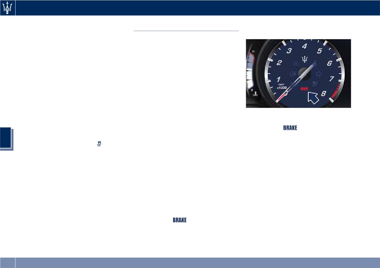
The indicator beside the displayed
will remain in the selected gear even
gear will light up just before reaching
when maximum engine speed is
the required speed to downshift
or
reached. The transmission will
upshift
(example in the figure).
upshift only if enabled by the driver.
Manual upshift or downshift will be
maintained as long as SPORT mode is
selected, even by full stroke pedal
press.
• If in M (Manual) or in SPORT mode,
Manual mode can be activated at any
the transmission will automatically
time, with no need to release the
downshift as the vehicle slows to
brake pedal.
halt (to prevent engine lagging) and
Even if the release button is pressed
the current gear will be displayed on
and gear is shifted in R (Reverse), P
the instrument cluster. Shifting the
(Park) or N (Neutral), the selected
shift lever backward (+) or moving
manual mode will be maintained.
the right shift paddle (+) towards
5
In Manual mode, the transmission will
the steering wheel when stationary,
shift up or down (+/-) if manually
will cause the vehicle to start in
selected by the driver by using the
second gear. If the vehicle speed is
shift lever, or shift paddles on the
too low, the system will ignore
steering wheel (if present). The
further upshifts. Avoid using speed
transmission remains in the engaged
control when the M (Manual) mode
gear until the driver shifts into
is engaged.
another higher or lower gear, except
Gear Shift Indicator Light
in the following cases.
When the new gear is engaged, the
In order to improve fuel economy, we
• Lack of accelerator pedal activity will
indicator turns off. If the shift runs
recommend that you shift gears when
cause the transmission to revert to
late or is not performed at all, the
the system prompts you to do so. This
automatic operation. The
indicator remains lit for a few seconds
will help reduce fuel consumption
transmission will also upshift
then turns off. As soon as new
without significantly affecting vehicle
automatically once maximum engine
conditions requiring further gear
performance.
speed is reached.
223
Driving
change occur, the indicator light will
Cluster” in section “Dashboard
Parking Brake
illuminate again.
Instruments and Controls”).
The vehicle is equipped with an
NOTE:
electric automatic parking brake, also
The gearshift indicator will only work
called EPB (Electric Parking Brake).
when the transmission is set in M
The EPB braking action on model with
(Manual) mode.
“Base” braking system (equipped with
rear floating calliper) is ensured by a
I.C.E. Mode excluding ESC
power actuator directly working on
To release the vehicle in low grip
the brake pad inside each calliper of
conditions (e.g.: heaps of snow, mud,
the rear brake system.
sand, etc), it is possible to shift the
All other modes with “Dual Cast”
transmission feature in the specific
braking system are equipped with a
mode as required for these situations,
dedicated calliper which acts on each
During engagement and
by pressing the I.C.E. button and to
rear brake disc.
disengagement procedures, the
warning light
flashes until the
exclude completely the yaw and
It can be automatically engaged when
spinning control system, by pressing
the engine is turned off and
parking brake has reached its
5
the button for two seconds
(ESC
disengaged with engine running,
maximum activation force and is
OFF).
driver seatbelt latched and driver door
respectively fully released.
closed, while pressing the brake pedal
In the above-mentioned conditions,
and operating the shift lever.
the automatic engagement function
Furthermore, EPB can be automatically
can be deactivated/activated by
engaged above a slope threshold with
selecting the menu item “Vehicle
the gearshift in P (Park) to avoid
settings” on the main menu (refer to
damage to the vehicle. EPB can be
paragraph “Deactivating Automatic
disengaged before turning off the
Operation” in this chapter).
vehicle.
Manual Engagement/
When the parking brake is applied, the
Disengagement
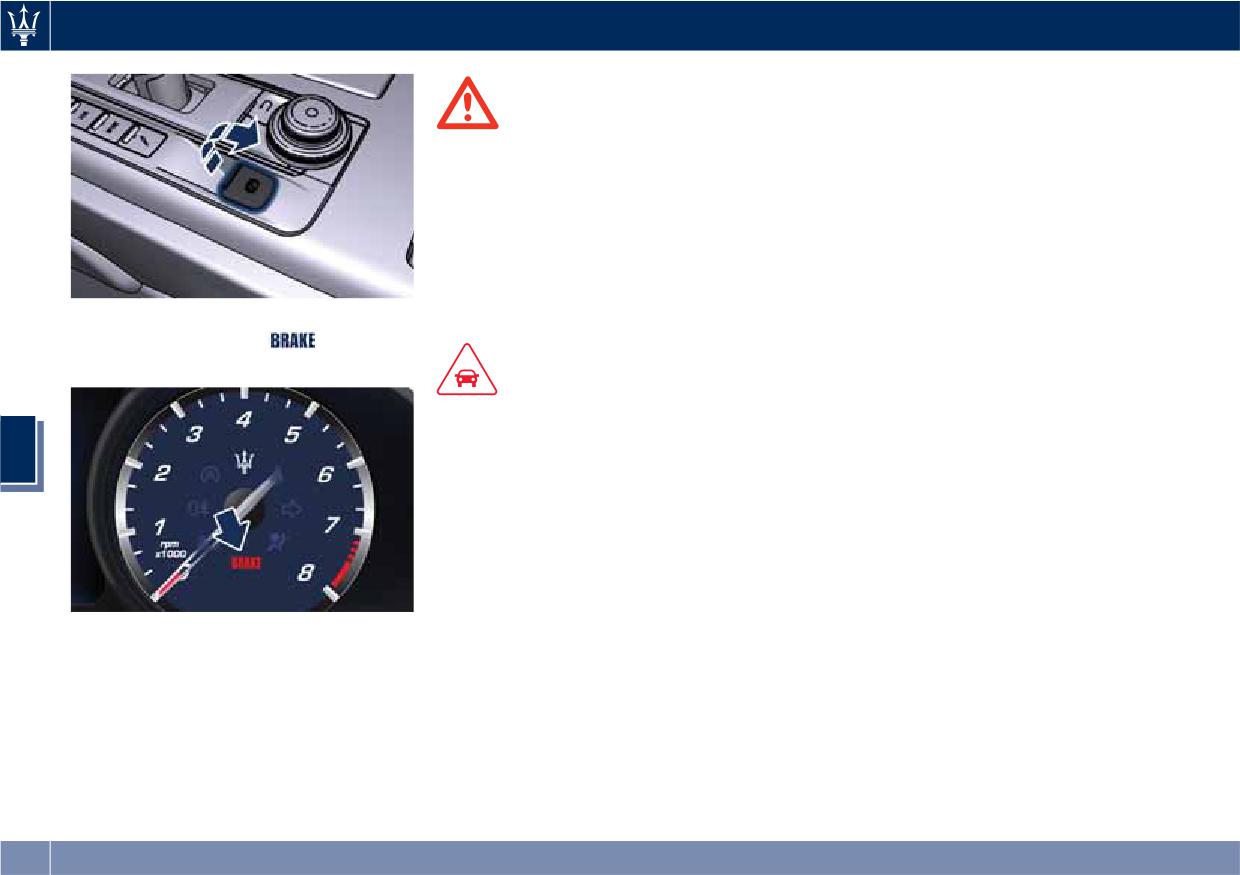
warning light
lights up on the
tachometer display and the related
The parking brake can also be
message is displayed on the instrument
manually engaged or disengaged
cluster for 5 seconds (see “Instrument
when the engine is running or the
ignition switch is in the RUN position,
224
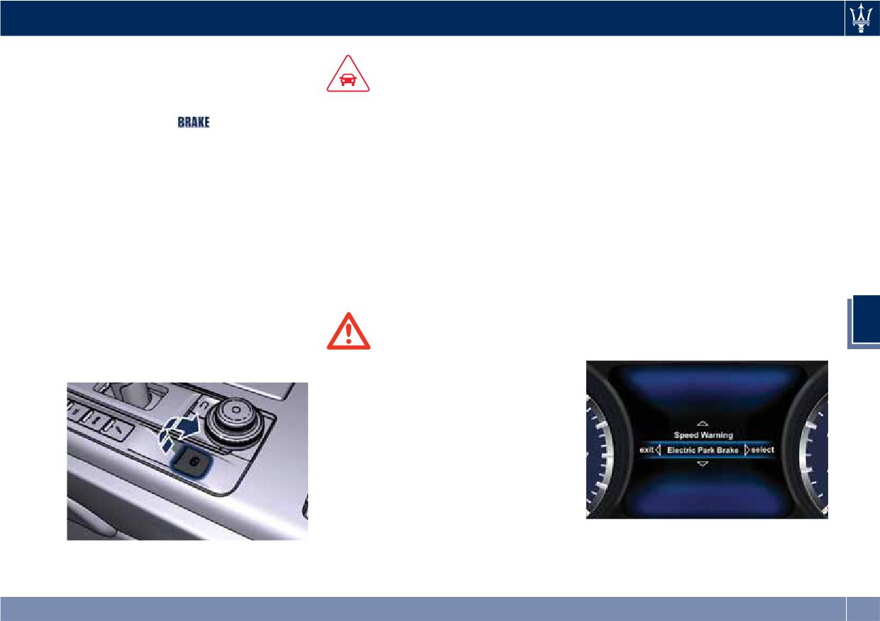
Driving
by pressing the brake pedal and
• It is advisable to keep the "Auto
raising the lever located behind the
Apply" function always active (On)
CAUTION!
shift lever.
so that the vehicle is properly
When the parking brake is applied,
The main function of the EPB is to
secured with electric parking brake.
the warning light
lights up on
allow safe parking of the vehicle,
the tachometer and the related
therefore it must only be applied
Deactivating Automatic
message will be displayed for 5
when the vehicle is already stationary.
Operation
seconds on the instrument cluster.
If the EPB is used while the vehicle is
moving and decelerating until a speed
The automatic engagement function
If you attempt to engage/disengage
lower of 3 mph (5 km/h) and, in
can be deactivated/reactivated by
the parking brake without having
particular, until complete stop
selecting the menu item “Vehicle
pressed the brake pedal, a message
(typically in a sudden brake), it is
settings” through the switch on the
will be displayed, warning you to
necessary to have the EPB system
right side of the steering wheel (refer
proceed.
checked by an Authorized Maserati
to “Instrument Cluster” in section
If the engine was turned off when the
Dealer.
“Dashboard Instruments and
automatic engagement device was
Controls”.)
deactivated (see “Deactivating
Press and release the switch toward
Automatic Operation” in this chapter)
5
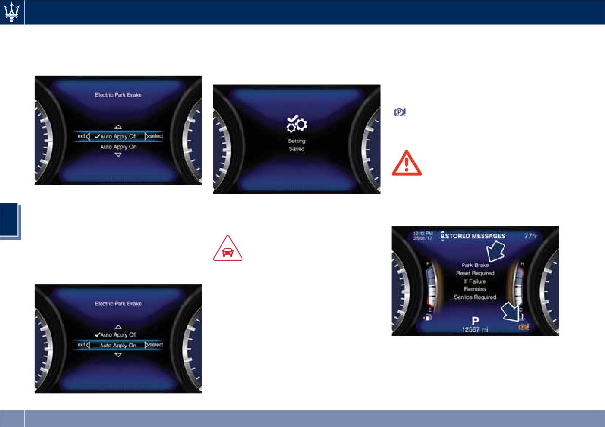
the arrow (►) to select “Electric Park
it is possible to shift the parking brake
WARNING!
Brake”.
simply by pulling the lever upward
• Always hold the brake pedal pressed
within 3 minutes after turning off.
during engagement or
disengagement of the parking
brake.
• The EPB command activation while
running generates a deceleration of
the vehicle with strong deceleration
(Dynamic Braking). It is therefore
recommended to use this feature
only in case of emergency. The
stability of the car is guaranteed by
Press and release the switch once
the action of the activated ESC
again toward the arrow (►) to
system.
visualize the options connected to this
function.
225
Driving
• Auto Apply On (recommended
“Setting Saved” Selection notification
on the TFT display, please contact an
setting);
appears as a popup for 2 seconds then
Authorized Maserati Dealer.
• Auto Apply Off.
the display will show again the
modified function.
Failure Indication
In the event of electric parking brake
system failure, the warning light
on the display will light up and the
related message will show for 5
seconds.
WARNING!
In the event of an EPB failure, take
Scroll with the switch toward the
your vehicle to the nearest Authorized
arrow ▲ or ▼ through the
In order to disable the automatic
Maserati Dealer as soon as possible.
programmable options.
operation follow the same procedures
5
Press and release the switch toward
and select the other option.
the arrow (►) to set the selected
option. A check mark will remain next
CAUTION!
to the previously-selected item until a
new selection is made.
• Under certain conditions when the
battery voltage is low, the electric
automatic parking brake system may
temporarily be deactivated for safety
reasons. Therefore, typically upon
starting the engine, when the
battery voltage drops, a message
Initialize the EPB System after
may temporarily be displayed,
Re-connecting the vehicle battery
indicating that automatic operation
After the detachment and the
is temporarily disabled.
subsequent connection of the battery,
• In case of repetitive requests to reset
the EPB through the messages shown
226
Driving
on the instrument cluster display the
and away from the curb on an uphill
Parking
warning light
will be illuminated.
grade.
To initialize the EPB system, lift,
Before leaving the vehicle, make sure
Apply the parking brake before
release and lift again the lever located
that the parking brake is fully applied
placing the shift lever in P (Park),
behind the shift lever.
and place the shift lever in the P (Park)
otherwise the load on the
position.
transmission locking mechanism may
Emergency Disengagement
make it difficult to move the shift
In case of brake lock with complete
lever out of P (Park).
electrical system failure, it is necessary
WARNING!
In certain conditions, it is however
to force the electric actuator on the
advisable to disengage the parking
rear calipers (see “Emergency Release
• Always check that the vehicle is
brake manually and slightly apply the
of the Parking Brake” chapter in
locked before leaving it.
service brake for starting off. This is
section “In an Emergency”).
• Never leave children unattended in
advisable when there are obstacles
the vehicle.
EPB Operation with
very close to the vehicle in the
Overheated Brakes
• Do not park the vehicle on paper,
direction in which you intend to move.
grass, dry leaves or other flammable
Driving on mountain roads with steep
materials.
slopes or a sports use of the vehicle
5
• Do not leave the engine running
could overheat the brake system
while the vehicle is unattended.
components. In these conditions, the
parking brake must not be used since
the push of the power actuator might
not be sufficient to ensure vehicle
CAUTION!
braking, especially on a slope.
When you need to park the vehicle on
Drive normally without braking to
a steep slope, both with the engine on
allow the brakes to cool down a few
or off, it is recommended not only to
minutes before stopping. In this way,
engage the parking brake, but also to
the automatic or manual activation of
shift the gearshift lever to P (Park)
the parking brake will ensure vehicle
before leaving the vehicle.
braking.
When parking on hill roads, it is
important to turn the front wheels
toward the curb on a downhill grade
227
Driving
“Drive Away Inhibit” strategy
“Drive Away Inhibit” strategy alerts
The table shows the vehicle condition
the driver with messages on the
and the action that the system runs to
In order to avoid a dangerous
instrument cluster display and
exit the dangerous condition.
condition resulting from leaving the
sounding chimes, then puts the
vehicle not “braked” with running
transmission in P (Park).
engine and without driver on board,
Vehicle condition
Action of the driver
• Engine running and speed lower than
1.8 mph (3 km/h).
• Transmission in any position other P
The driver releases the brake pedal to
(Park).
get out of the vehicle.
• Driver safety belt unlocked.
The system puts the
• Driver door opened.
transmission in P
• Brake pedal pressed.
(Park) position.
Warnings
Warnings
5
• Slow continuous chime.
• Fast chime.
• The condition of the vehicle not in P
• A message which invites to engage
(Park) position will be signaled by a
the parking brake to prevent vehicle
message on the display.
movement will be displayed on the
display.
228
Driving
the condition of the vehicle brakes
of discrepancy between the required
Brake and Stability
and tires.
trajectory and the current one, the
Control System
ESC system brakes the appropriate
• These systems cannot prevent
wheel to counteract over or under
The vehicle is equipped with an
collisions, including those resulting
steering.
Electronic Stability Control System
from excessive speed in turns,
(ESC), which helps to maintain
following another vehicle too
• Oversteer - when the vehicle is
directional control in the event of loss
closely, or aquaplaning.
turning more than appropriate for
of grip of the tires. The system is able
the steering wheel position.
• The capabilities of a vehicle
to detect potentially dangerous
equipped with these systems must
• Understeer - when the vehicle is
situations for the stability of the
never be exploited in a reckless or
turning less than appropriate for the
vehicle and automatically sets the
dangerous manner that could
steering wheel position.
brakes on all four wheels in a
jeopardise the driver’s and the
The ESC system has two available
differentiated manner, in order to
passenger’s safety or the safety of
operating modes:
provide a torque settlement of the
others.
ESC on
vehicle.
This is the normal ESC operating
ESC includes the following subsystems:
Electronic Stability Control
mode. At each start-up of the vehicle,
5
• ABS (Anti-lock Braking System);
(ESC)
the ESC system is set in this mode and
• EBD (Electronic Brake-force
should be used for most driving
This system enhances directional
Distribution);
conditions. The ESC should only be
control and stability of the vehicle
• TCS (Traction Control System);
turned off for specific reasons as
under various driving conditions. The
pointed out in the following
• BAS (Brake Assist System);
ESC corrects over steering and under
paragraphs.
• BTO (Brake Throttle Override);
steering of the vehicle by applying the
brake to the appropriate wheel.
ESC off
• HSA (Hill Start Assist).
Engine power may also be reduced to
The “ESC off” mode is aimed for a
assist in counteracting the conditions
more spirited driving experience but
of instability and maintain the right
also purposeful for driving in deep
WARNING!
direction. The system is also able to
snow, sand, or gravel. The current
• These systems cannot prevent the
reduce the engine power.
mode disables the TCS portion of the
natural laws of physics from
Through sensors fitted on the vehicle,
ESC and raises the threshold for ESC
affecting the vehicle, nor can they
the ESC system detects the driver’s
activation, allowing higher wheel spin
increase traction, braking or steering
chosen direction comparing it to the
than normally granted by the ESC
efficiency beyond that afforded by
one maintained while running. In case
system. The
(ESC OFF) button is
229
Driving
fitted beside the gear shift lever: to
situation requiring “ESC off” mode is
NOTE:
deactivate the system see “Drive
overcome, turn the ESC on again by
• When the vehicle's speed is higher
Mode” in this section.
pressing the
(ESC OFF) button. This
than 7 mph (11 km/h), you may hear
may also be performed while in
a slight clicking sound as well as
motion.
other motor noises. The system is
WARNING!
performing a self-check cycle to
In SPORT mode the ESC control
Anti-Lock Braking System (ABS)
ensure that the ABS is working
thresholds are higher for maximum
and Electronic Brake-force
properly.
performance on dry road surface. To
Distribution (EBD)
• This self-check occurs each time the
ensure maximum security of the ESC,
vehicle is started and accelerated
The Anti-Lock Braking System (ABS)
it is recommended not to activate
past 7 mph (11 km/h).
provides increased vehicle stability and
SPORT mode on surfaces with
brake performance under most
ABS is activated during braking under
medium- and low-grip (e.g., wet,
braking conditions. The system
certain road or stopping conditions.
snow, dirt, etc..) with ESC system
automatically “pumps” the brakes
ABS-inducing conditions can include
active (
(ESC OFF) button not
during severe braking to prevent
ice, snow, gravel, bumps, railroad
pressed).
wheel lock-up.
tracks, loose debris.
5
The Electronic Brake-force Distribution
You may also experience the following
NOTE:
(EBD) prevents the rear wheels from
when the brake system goes into Anti-
• When in “ESC off” mode, the TCS
over-braking and provides greater
Lock:
functionality of ESC is deactivated
control of available braking forces
• The ABS motor running (it may
(except for the limited slip feature
applied to the rear axle.
continue to run for a short time after
described in the TCS paragraph of
the vehicle stops).
this chapter). All other stability
features of ESC function regularly.
• The clicking sound of solenoid valves.
WARNING!
• To improve the vehicle's traction
• Brake pedal pulsations.
The ABS helps prevent the wheels
when driving with snow chains, or
• A slight drop or fall away of the
from locking, but it does not increase
when starting off in deep snow,
brake pedal at the end of the stop.
the physical grip limits between the
sand, or gravel, it may be desirable
These are all normal characteristics of
tires and the road. Therefore, always
to switch to the “ESC off” mode by
ABS functioning.
keep a safe distance from the vehicle
pressing the
(ESC OFF) button and
in front of yours and reduce your
remain in this operational mode no
speed when entering a curve.
longer than needed. Once the
230
Driving
Activating under slip conditions
the vehicle even when it is being
different control systems:
accelerated. If the brake pedal is
WARNING!
depressed together with the
• if slippage affects both drive wheels,
• The ABS contains sophisticated
accelerator, the system does not
it reduces the power transmitted by
electronic equipment that may be
consider as “conflict” the sequence
the engine;
susceptible to interference caused
“brake-first-then-accelerator” of pedal
• if slippage only affects one drive
by improperly installed or high
application and it will not engage the
wheel, it brakes the slipping wheel
output radio transmitting
BTO. When the system recognizes the
automatically.
equipment. This interference can
sequence “accelerator-first-then-
cause possible loss of anti-lock
brake-pressed” as “conflict” the
Brake Assist System (BAS)
braking capability. Installation of
engine power should be automatically
such equipment should be
This system completes the ABS system
reduced and, if the driver continues to
performed by qualified Maserati
by optimizing the vehicle braking
depress the accelerator, the system can
personnel.
capacity during emergency brake
make the vehicle to come to a
maneuvers. The system detects an
• Pumping the Anti-Lock Brakes will
complete stop.
emergency braking situation by
diminish their effectiveness.
Additionally, if the brake pedal is
sensing the rate and amount of brake
Pumping brakes makes the stopping
released when the accelerator is still
5
application and then applies optimum
distance longer. Just press firmly on
depressed, the corresponding engine
pressure to the brakes in order to help
your brake pedal when you need to
torque increase gradually to a safe
reduce braking distances.
slow down or stop. Do not pump
value.
The quick brake coupling is optimal
brakes.
During this event, the ETC light
for BAS performances. In order to fully
indicator will illuminate. The system
exploit the system, apply continuous
exits from this strategy when the
Traction Control System (TCS)
brake pedal pressure during the entire
accelerator pedal is completely
The current device is an integral part
vehicle stop sequence. Do not reduce
unstuck.
of the ESC system. It operates
brake pedal pressure earlier than
automatically by reducing the power
required. Once the brake pedal is
Hill Start Assist (HSA)
transmitted by the engine in case of
released, the BAS is deactivated.
The HSA system is designed to assist
slipping, loss of grip on wet floor
Brake Throttle Override (BTO)
the driver when starting a vehicle
(aquaplaning), acceleration on
uphill. HSA will maintain the level of
slippery snow-covered or frozen
To complete the range of systems that
brake pressure applied for a short
surfaces, etc.
assist braking, the vehicle is equipped
period of time also after releasing the
with BTO, which is designed to stop
brake pedal.
231
Driving
If the driver does not apply the
abnormally high brake temperatures,
Using the Brakes
throttle during this short period of
excessive lining wear, and possible
time, the system will release brake
brake damage. In an emergency full
pressure and the vehicle will start
braking capacity may be impaired.
CAUTION!
sloping down. The system will release
To obtain a good performance by
brake pressure proportionally to the
Brake Pads and Brake Discs
brake pads and discs, avoid sudden
amount of throttle/torque applied as
braking during the first 190 mi
Wear on the brake pads and brake
the vehicle starts to move in the
(300 km).
discs depends to a great extent on the
chosen direction.
driving style and the conditions of use
HSA Activation Criteria
The pad wear limit is indicated by the
and therefore cannot be expressed in
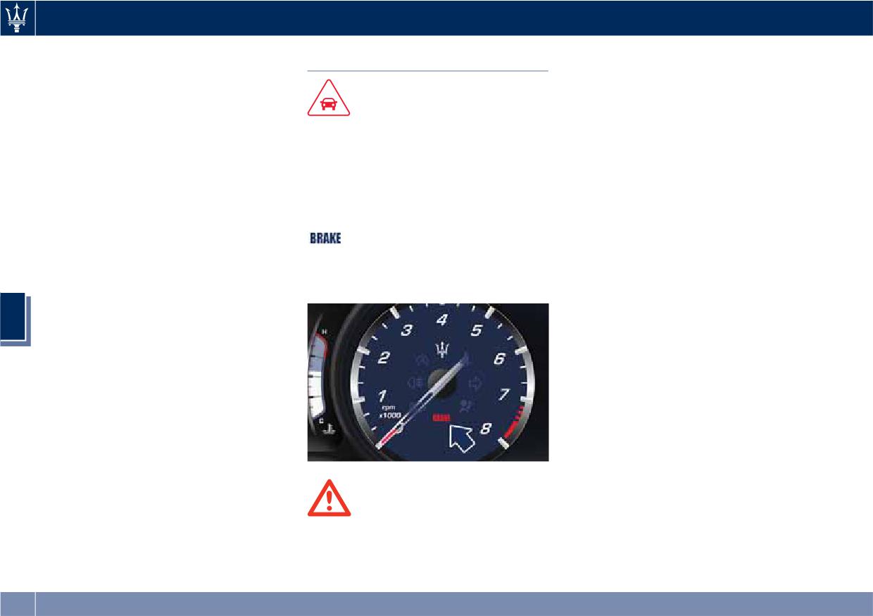
illumination of the warning light
The following criteria must be met in
actual miles driven on the road.
and by a message on the
order for HSA to activate:
The brake system is designed for
instrument cluster.
optimal braking effect at all speeds
• vehicle is stationary;
In this event, please contact an
and temperatures.
• gear selection matches vehicle uphill
Authorized Maserati Dealer.
Certain speeds, braking forces and
direction (i.e., vehicle facing uphill is
ambient conditions (e.g. temperature,
5
in forward gear; vehicle backing
humidity and long outdoor stopping
uphill is in reverse gear).
periods) can therefore cause the
HSA will work in R (Reverse) and all
brakes to "squeal". This is normal and
forward gears when the activation
will cease after a few brakings.
criteria have been met.
The system will not activate if the gear
New Brake Pads and/or Brake
is placed in N (Neutral) or P (Park).
Discs
New brake pads have to be “broken
in”, and therefore only attain optimal
friction to the brake disc when the
vehicle has covered several hundreds
of miles.
WARNING!
During this break-in period, the
Riding the brakes can lead to brake
slightly reduced braking ability must
failure and possibly an accident.
be compensated for by pressing the
Driving with your foot resting or
brake pedal harder. This applies
riding on the brake pedal can result in
232
Driving
whenever the brake pads and/or brake
of the break-in and not interpreted as
Use of the Engine
discs are replaced.
an indication of malfunction.
Breaking-In
Specific Requirements
Brake Overheating
Today's most modern production
Avoid exceeding 5000 rpm for the first
Driving on mountain roads with steep
methods are designed to provide
620 mi trip (1000 km).
slopes or a sports use of the vehicle
extremely precise construction and
After starting the vehicle, do not
could overheat the brake system
assembly of components. However,
exceed 4000 rpm until the engine has
components. In these conditions, the
moving parts do undergo a settling
warmed up sufficiently (coolant
parking brake must not be used since
process, basically in the first hours of
temperature: 149-158°F /65 70°).
the push of the power actuator might
vehicle operation.
not be sufficient to ensure vehicle
While Driving
Do not drive keeping at a constant
braking, especially on a slope.
high speed rate for a prolonged time.
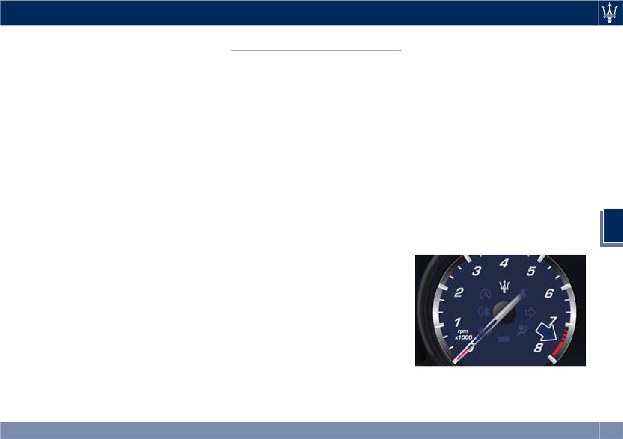
Never travel with the tachometer
Drive normally without braking to
While cruising, brief full-throttle
indicator approaching the peak rpm,
allow the brakes to cool down a few
acceleration within the limits of local
not even downhill. When the
minutes before stopping. The
traffic laws contributes to a good
tachometer indicator is approaching
automatic or manual activation of the
break-in. Wide-open throttle
the peak rpm (red colored zone), take
parking brake will ensure vehicle
acceleration in low gear can be
precautions to avoid exceeding that
5
braking.
detrimental and should be avoided.
limit.
Brake overheating could also cause
The engine oil installed in the engine
“squeals”.
at the factory is a high-quality energy
conserving type lubricant. Oil changes
should be consistent with anticipated
climate conditions under which vehicle
operations will occur. For the
recommended viscosity and quality
grades, see “Refillings” in section
“Features and Specifications”.
A new engine may consume some oil
during its first few thousand
Ensure proper operation of different
miles/kilometers of operation. This
devices checking their respective
should be considered as a normal part
control telltales.
233
Driving
Authorized Maserati Dealer will use to
will soon occur. Immediate service is
service your vehicle. Although the
required at an Authorized Maserati
CAUTION!
vehicle will still be driveable and not
Dealer.
• Under normal conditions, all red
need towing, contact an Authorized
• After the problem has been solved,
warning lights on the instrument
Maserati Dealer for service as soon as
the Authorized Maserati Dealer
cluster display should be off. When
possible.
personnel will perform specific tests
they come on, this indicates a
for a complete check of the system
malfunction. Refer to “Instrument
and, if necessary, road tests.
Cluster” in section “Dashboard
Instruments and Controls”.
• Continuing to drive when a red
warning light is on could cause
serious damage to the vehicle and
affect its performance.
Onboard Diagnostic System
5
Your vehicle is equipped with a
sophisticated onboard diagnostic
system. This system monitors the
CAUTION!
performance of the emissions, engine,
• Prolonged driving with the
and automatic transmission control
Malfunction Indicator Light (MIL)
systems. When these systems are
on could cause further damage to
operating properly, your vehicle will
the emissions control system. It could
provide excellent performance and
also affect fuel economy and
fuel economy, as well as engine
drivability. The vehicle must be
emissions well within current local
serviced before any emissions tests
regulations of various countries.
can be performed.
If any of these systems require service,
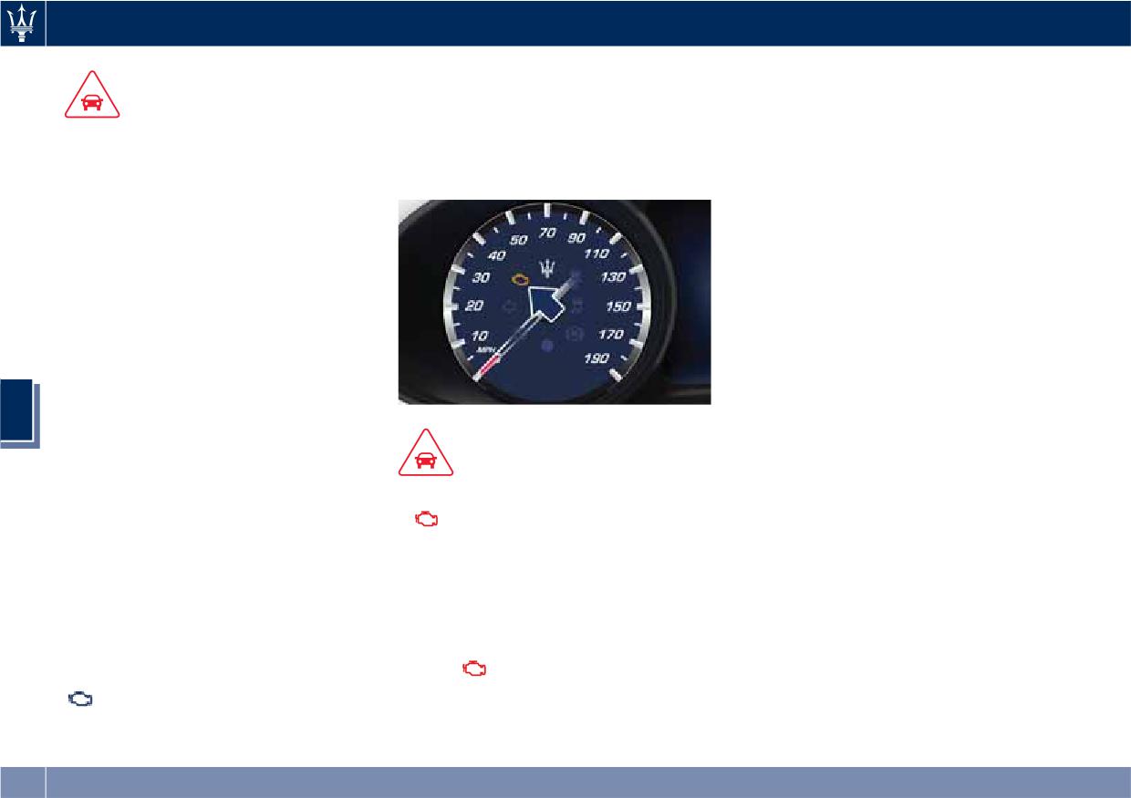
• If the
Malfunction Indicator
the system will turn on the
Light (MIL) is flashing while the
Malfunction Indicator Light (MIL).
engine is running, severe catalytic
It will also store diagnostic codes and
converter damage and power loss
other information, which your
234
Driving
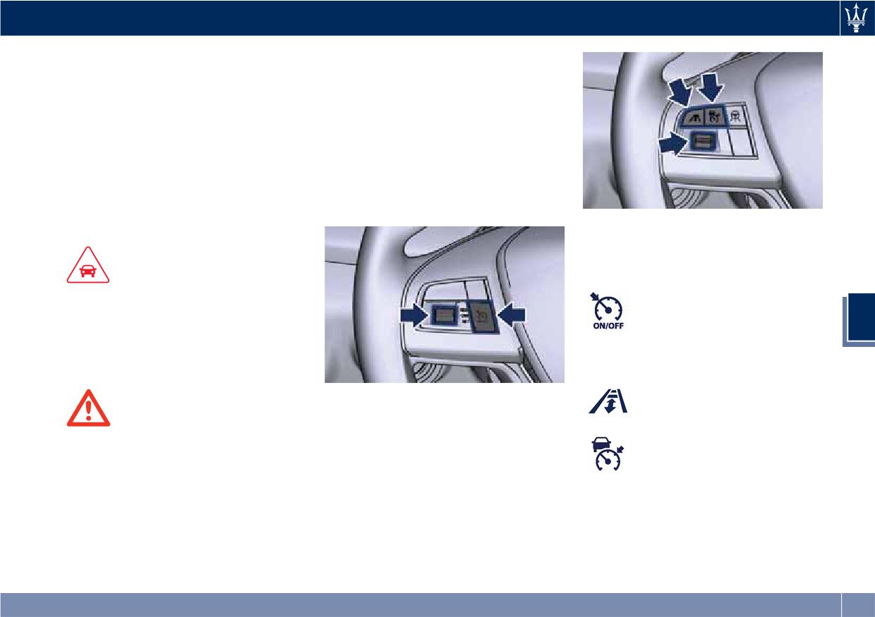
Electronic Cruise Control Controls
The electronic Cruise Control controls
The electronic Cruise Control (CC)
are located on the left side of the
enables the driver to maintain the
steering wheel.
desired vehicle speed without pressing
Control configuration depends on
the accelerator pedal, reducing driving
which driver assist systems are
fatigue on highways, especially long
installed to the vehicle.
trips, as the set speed is automatically
In the standard configuration there is
maintained. A firm press on the
a specific button to enable and disable
accelerator pedal or the braking pedal
the CC.
will temporarily deactivate the cruise
Optional Configuration
control function.
Control buttons have the following
functions:
CAUTION!
Standard Configuration
The device can only be switched on at
ON/OFF button to
speeds exceeding 18 mph (30 km/h)
engage/disengage CC
5
and it switches off automatically when
system.
the brake pedal or the accelerator
pedal is pressed.
Optional Configuration
Press ACC Gap button and
Standard Configuration
hold it down for 2 seconds
In the optional configuration, there is
WARNING!
to enable the CC system.
no specific button to enable and
The Cruise Control function must only
disable the CC, since the driver uses
Press ACC button to disable
be activated when traffic and the
the ACC control buttons.
the CC system.
route permit a constant speed to be
maintained safely for a sufficiently
long distance.
235
Driving
Shared by All Configurations
Displayed Information
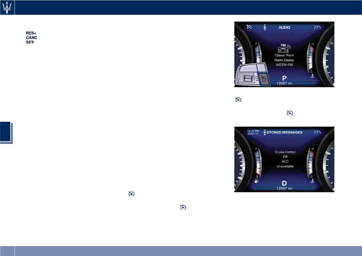
Multifunction switch:
CC conditions are displayed on the
• Press up (indication RES
instrument cluster after selecting
+): increase speed, set
“Driver Assist” menu (see paragraph
current speed or resume
“TFT Display: Menus and Settings"
previously set speed
under “Instrument Cluster” in section
when system is in
“Dashboard Instruments and
“cancelled” status;
Controls”).
• Pushed (indication
Displayed information depends on
CANC): deletes the set
system status: ready, disabled,
speed;
cancelled or set.
To turn the system off, push the
• Press down (indication
Apart from the pop-up messages at
ON/OFF button a second time or
SET -): set speed/decrease
the centre of the display, CC system
the ACC button (in the Optional
speed.
status is represented by icons at the
Configuration). The
white light will
top left. These icons remain displayed
turn off.
NOTE:
even when you exit the "Driver Assist"
5
screen.
• The figures only show the Standard
The CC screen can be displayed any
Configuration.
time the driver changes system status
• In order to ensure proper operation,
or settings. After 5 seconds of CC
the CC system has been designed to
inactivity, the display goes back to last
shut down if multiple systems are
screen.
operated at the same time (example:
ACC and FCW). When conditions so
Activation
allow, the CC system can be
To turn the system on, push the
reactivated by pushing the CC
ON/OFF button or the ACC Gap
“ON/OFF” button or the ACC Gap
NOTE:
button for 2 seconds (in the Optional
button (in the Optional
Configuration). The
white light
The CC system must be turned off
Configuration) and resetting the
with below 3 dashes on the instrument
when not in use.
desired vehicle set speed.
cluster display will illuminate.
236
Driving
will be visualized below the green
light.
WARNING!
To decrease speed, push downward
Never leave the electronic Cruise
the multifunction switch (SET -).
Control system on when not in use.
Keeping the switch pushed in the
You could accidentally set the system
downward position, the set speed will
or cause it to go faster than you want.
continue to decrease by 5 units at a
Always leave the system off when
time (5 mph or 5 km/h) until the
you are not using it.
switch is released. Release the switch
when the desired speed is reached,
Speed Range of Use
and the new set speed will be
Release the accelerator and the
visualized below the green light.
vehicle will operate at the selected
Speed
mph (km/h)
Pushing the multifunction switch
speed.
Minimum
18 (30)
upward (RES +) or downward (SET -)
NOTE:
once will enable to increase or
Engaged/activated
18 (30)
The vehicle should be traveling at a
decrease the set speed by one unit
Maximum
130 (210)
steady speed and on level ground
(1 mph or 1 km/h).
5
before pushing the switch downward.
Each subsequent tap of the
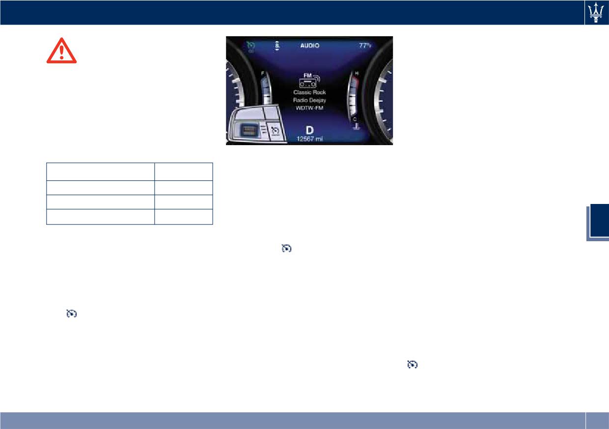
Setting Desired Speed
multifunction switch will increase or
Pressing the
“ON/OFF” button or
decrease the speed by 1 mph or
Turn on the CC function. When the
the ACC Gap button for 2 seconds (in
1 km/h.
vehicle has reached the desired speed
the Optional Configuration) or
(in the example: 60 mph), push
moving the ignition switch in OFF
Temporary Deactivation
downward the multifunction switch
position erases the set speed memory.
A soft tap on the brake pedal,
(SET -) and release.
pressing the multifunction switch
The
green light below the desired
Changing Speed Setting
(CANC), or normal brake pressure
speed will illuminate on the
When the CC is set, you can increase
while slowing the vehicle will
instrument cluster display.
cruise speed by pushing upward the
temporarily deactivate the CC without
multifunction switch (RES +). Keeping
erasing the set speed memory. The
the switch pressed, the set speed will
white light will appear on the
continue to increase by 5 units at a
display.
time (5 mph or 5 km/h) until the
switch is released. The new set speed
237
Driving
below the set speed with steady light
traffic or on winding, icy,
will be displayed.
snow-covered or slippery roads.
Resume Speed
To resume a previously set speed, push
upward the multifunction switch (RES
+) and release. The
green light with
below the set speed will illuminate on
the instrument cluster. Resume can be
used at any speed above 18 mph
(30 km/h).
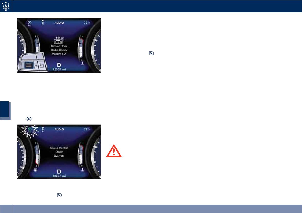
Driver Override
If the driver presses the accelerator
Using Electronic Cruise Control
pedal while the CC is on, such as to
on Hills
overtake another vehicle, and exceeds
The transmission may be downshifted
the set speed limit, the system will
on hills to maintain the vehicle set
temporarily deactivate the CC. During
speed. The CC system maintains set
5
the event, the speed indication below
speed up and down hills. A slight
the
green light will be blinking.
speed change on moderate hills is
normal. On steep slopes, a greater
speed loss or gain may occur so we
recommend to drive without CC.
WARNING!
Electronic Cruise Control can be
dangerous where the system cannot
maintain a constant speed. Your
vehicle could go too fast for the
When the accelerator pedal is
conditions, and you could lose control
released, the vehicle will return to the
and have an accident. Do not use
set speed and the
green light with
electronic Cruise Control in heavy
238
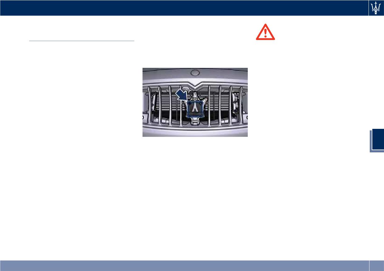
Driving
on the front grille behind the trident,
Adaptive Cruise Control -
and the forward-facing camera behind
ACC (optional)
WARNING!
the internal rear-view mirror to detect
the presence of a vehicle ahead at a
• The Adaptive Cruise Control (ACC) is
ADAS Equipments
close distance and moving in the same
designed to increase vehicle driving
The Adaptive Cruise Control (ACC) is
direction.
comfort. It must not be considered
part of ADAS equipments together
as a means of replacing the required
with:
attention of the driver. The driver is
always required to drive carefully.
• Forward Collision Warning (FCW)
The driver is always required to pay
• Lane Keeping Assist (LKA)
utmost attention to driving
• Active Blind Spot Assist (ABSA)
conditions (road, traffic, weather)
• Highway Assist (HAS)
and style (speed, distance from
• Traffic Sign Assist (TSA).
sensed vehicle ahead, brake use).
Driver has the full responsibility of
NOTE:
the vehicle therefore his attention is
FCW, LKA ABSA, HAS and TSA are
crucial to keeping vehicle control, in
5
described in the relevant chapters of
This vehicle, in this chapter, will be
particular when approaching curves
this section.
indicated as "target vehicle" or
and situations with heavy traffic.
"vehicle ahead".
Failure to follow these warnings can
result in a collision and death or
ACC Preview
NOTE:
serious personal injury.
The Adaptive Cruise Control (ACC)
• If the sensor detects no vehicle
ahead, the ACC system will maintain
• In some driving scenarios, the ACC
further increases the drive comfort
set steady speed.
could have detection problems. In
ensured by the Cruise Control when
such cases, the ACC could kick in late
driving on highways and freeways.
• If the ACC sensor detects a vehicle
or unexpectedly. The driver must be
Always consider that ACC is not a
ahead, the ACC system automatically
careful since his/her intervention
safety system and is not designed to
kicks in by slightly accelerating or
could be necessary.
prevent accidents.
braking (to avoid exceeding the
The ACC allows driver to keep Cruise
initially set speed) so that the vehicle
• It is always the driver’s responsibility
Control active in limited or moderate
keeps present distance, trying to
to obey speed limits and to keep
traffic conditions with no need to
adapt to the speed of the detected
minimum legal distance to the
constantly restore the Cruise Control.
vehicle ahead.
preceding vehicle.
The ACC uses a radar sensor, located
(Continued)
239
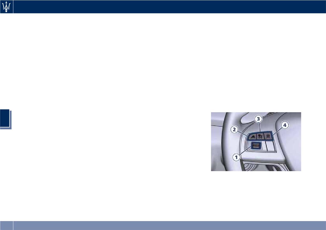
Driving
(Continued)
similar complex situations such as
(green); the white, grey or yellow lines
• ACC system can decelerate only with
highway construction zones.
represent the LKA and HAS systems.
limited braking, it cannot execute
The ACC screen can be displayed any
• When entering a junction lane or a
emergency braking.
time driver changes system status or
slip road to leave the highway; when
driving on narrow, icy, snowy,
settings. After 5 seconds of ACC
The ACC system:
inactivity, the display goes back to last
slippery roads, or on steep uphill and
• Does not activate/react in the
downhill roads.
screen.
presence of pedestrians, bicycles,
• When circumstances do not allow to
incoming traffic from the opposite
ACC Controls and Activation
drive safely at constant speed.
direction and steady objects such as a
Conditions
vehicle stuck in a traffic jam.
Displayed information
The buttons on the RH side of the
• Is meant for the use on highways and
steering wheel control the ACC
Adaptive Cruise Control (ACC)
well-built roads, not for city traffic or
operations and the other
condition, as well as the LKA and HAS
mountain roads.
functions/driver assist systems installed
status, is displayed on instrument
• May not have enough time to react
to this vehicle.
cluster after selecting “Driver Assist”
and/or decelerate sufficiently on
menu (see paragraph “TFT Display:
vehicles when lane is changed too
5
Menus and Settings" under
quickly or the relative speed is too
“Instrument Cluster” in section
high. In such cases the driver has to
“Dashboard Instruments and
react appropriately and without any
Controls”).
acoustic/visual and warning.
Displayed information depends on
• Cannot consider road, traffic and
system status: ready, set, temporarily
weather conditions and might prove
cancelled or override.
limited when visibility is poor.
Apart from the image at the center of
• Does not always fully recognize
the display, CC, ACC, LKA and HAS
complex driving conditions and this
systems status is represented by icons
could cause an incorrect assessment
at the top left and right. These icons
of the required safety distance.
remain displayed even when exiting
It is recommended to disable the ACC
the "Driver Assist" screen.
system in the following instances:
The vehicle(s) and horizontal bars
represent the ACC status as ready
• When driving in the fog, heavy rain,
(white) or with sensed vehicle ahead
heavy snow, slush, heavy traffic and
240
Driving
NOTE:
as ACC and ABSA just to mention
1 Multifunction control shared by all
some.
Any change made to tire dimensions
driver assist functions/systems:
While activation of ACC and CC at the
affects performance of Adaptive
• Press up (indication “RES +”):
same time is impossible.
Cruise Control and Front Collision
increase speed, set current speed
Warning (FCW), if equipped.
or resume previously set speed
Speed Range of Use
when system is in “cancelled”
The ACC is not activated in the
status.
Speed
mph (km/h)
following conditions:
• Pushed (indication “CANC”):
Minimum
0 (0)
• When braking.
cancel the function if it was in
Engaged/activated
18 (30)
“set” status, going in a ready
• When parking brake is activated.
Maximum
130 (210)
condition but remembering the
• When automatic transmission is in P
previous set speed.
(Park), R (Reverse) or N (Neutral).
• Press down (indication “SET -”):
• When vehicle speed is out of preset
Activation/Deactivation
set speed/decrease speed.
speed range
NOTE:
2 Two functions button with ACC
• When brakes are overheated.
activated:
Pictures show status of ACC and LKA
• When driver door is open.
5
• ACC Gap: pressed and released;
systems.
• When the driver’s seat belt is
set the distance to sensed
unbuckled.
Press and release
ON/OFF button to
vehicle ahead as horizontal bars
• When the road is particularly steep
activate the ACC. The display will
(setting cycle starts to 3 bars).
(both uphill and downhill) at low
show the
white symbol with below
• CC On: pressed for 2 seconds
speed.
3 dashes will illuminate indicating that
activates the CC system.
• When drive mode
(ESC OFF) is
system is ready to be set.
• Press it to switch from CC to
ACC.
selected.
• When the door is opened at low
3 ACC ON/OFF button. If enabled,
speed.
pressing this button will disable
CC.
• When there has been an ESC event
in the last 5 seconds, or is still active.
4 HAS ON/OFF button with ACC set
only. See "Highway Assist - HAS"
• When there is an object too close in
in this section for further details.
front of the vehicle.
It is possible that more than one
system is active at the same time such
241
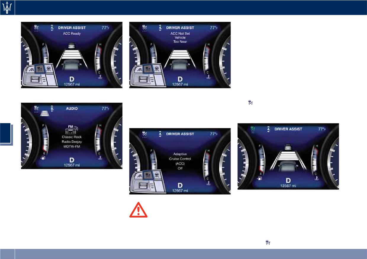
Driving
faster than you want. Always leave
the system off when you are not using
it.
Setting the Speed
When the vehicle reaches the required
speed, press down and release the
multifunction control (SET -). The
display will show set speed
corresponding to vehicle current one.
When in Driver Assist Page
Push the ON/OFF button a second time
Speed value will be indicated below
and release to turn the system off. A
the
green symbol and above the
pop-up message is displayed for 2
distance bars, in the center of the
seconds to indicate that ACC was
display.
disabled.
5
Out of Driver Assist Page
If a vehicle is detected as being too
close, the display will show a message
for 5 seconds and trigger a signal to
Remove foot from accelerator pedal
warn the driver that current conditions
and vehicle will continue at set speed.
do not allow enabling of the ACC. At
Driver Override
any rate, system will remain in the
WARNING!
ready status.
Leaving the Adaptive Cruise Control
If the driver accelerates beyond the set
(ACC) system on when not in use is
speed or faster than the car would do
dangerous. You could accidentally
with ACC engaged, the set speed
activate the system or cause it to go
below the
green light will blink and
242
Driving
the time gap bars will vanish to
• The ACC system applies the brake
the vehicle will temporarily deactivate
indicate that in this condition the
down to a full stop when following
the ACC without erasing the set speed
system cannot control the distance
a target vehicle. If an ACC host
memory. The
white light will appear
between vehicle and sensed vehicle
vehicle follows a target vehicle to a
on the display with below the set
ahead. Vehicle speed will be
standstill, after a two or three
speed.
determined only by the accelerator
second delay, the system will not be
Conditions for Disabling and
pedal position.
able to resume driving the car
Deactivation
autonomously. At this point it is
Changing Speed Setting
necessary for the driver to manually
Besides the cases specified in the
Once speed is set, driver can increase
reengage the system by either using
previous paragraph, the following
or decrease it by respectively pressing
the multifunction control (press SET-
conditions will disable the system:
multifunction control up (RES +) or
or RES+) or by pressing the
• Anti-Lock Brake (ABS) kicks in.
down (SET -). Speed can be increased
accelerator pedal (see “ACC
• Transmission lever is not in D (Drive).
or decreased in two ways:
Operation Before and During Stop”
in this chapter).
• The Electronic Stability Control and
• Pressing control once, set speed will
the Traction Control System
increase or decrease by one unit
• The ACC system maintains set speed
(ESC/TCS) activate.
corresponding to 1 mph (1 km/h).
when driving up hill and down hill.
5
However, a slight speed change on
• Vehicle parking brake is operated.
• Hold the control to increase or
moderate hills is normal. In addition,
• The driver safety belt is unbuckled at
decrease set speed by 5 mph
downshifting may occur while
low speed.
(10 km/h) at a time.
climbing uphill or descending
• The driver door is ajar at low speed.
NOTE:
downhill. This is normal operation
• The driver disabled the ESC using the
• When pressing the multifunction
and necessary to maintain set speed.
(ESC OFF) button on central
control up (RES +) or down (SET -),
When driving uphill and downhill,
console.
the new set speed will be the current
the ACC system will cancel if the
• The road is too steep both uphill and
speed of the vehicle.
braking temperature exceeds normal
downhill at low speed.
• When using (SET -) control to
range.
The system is deactivated and set
decelerate, if the engine braking
speed is deleted from system memory,
power does not slow down the
Temporary Deactivation
if the ACC ON/OFF button is pressed or
vehicle sufficiently to reach the set
A soft tap on the brake pedal, pushing
if ignition device is turned to OFF.
speed, the brake system will
the multifunction control (CANC), or
automatically slow down the vehicle.
normal brake pressure while slowing
243
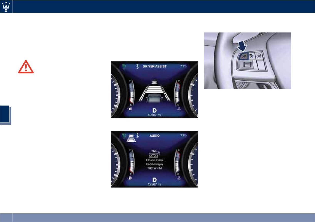
Driving
Resuming Speed
If system does not detect the presence
vehicle ahead, press and release the
of any vehicles ahead, only the bars
distance setting button.
If a speed setting is stored in system
referred to set distance will be
memory, press the multifunction
displayed.
control (RES +) up and take foot off
When system detects the presence of a
the accelerator pedal. The last set
vehicle ahead, it is displayed in front
speed will be displayed.
of the bars (see example in the figure).
WARNING!
The resume function should be used
only when road and traffic conditions
allow it. Resuming a too high or too
low speed for current traffic and road
Each press and release of the button
conditions could cause a harsh vehicle
changes the gap starting from 3 bars
acceleration or deceleration which
(default distance) and moving in a
could increase the risk of collisions
sequential way towards the minimum
5
and death or serious injury.
distance: 3→2→1→4→3→2→1→4 and so
When in Driver Assist Page
on.
If there is no vehicle ahead, the vehicle
Setting the ACC Gap
will maintain the set speed. If a slower
The specified ACC gap can be set by
moving vehicle is detected in the same
varying the distance setting among the
lane, the system displays the target
four possible options identified by the
vehicle icon before the bars. From that
number of horizontal bars:
moment, the system adjusts the vehicle
• Maximum (longest) distance: 4 bars.
speed automatically to maintain the
distance setting, regardless of the set
• Long distance: 3 bars (default
speed.
distance).
The vehicle will then maintain the set
• Medium distance: 2 bars.
distance until:
• Short distance: 1 bar.
Out of Driver Assist Page
• The vehicle ahead accelerates to a
Using this distance setting and the
To increase or decrease the number of
speed above the set speed.
vehicle speed, ACC calculates and sets
bars, corresponding to the gap from
the gap to the vehicle ahead.
244
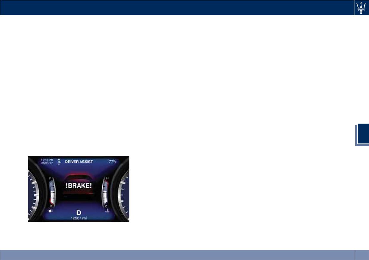
Driving
• The vehicle ahead moves out of the
NOTE:
determines that the vehicle has moved
lane or view of the sensor.
back to a location with left hand
The displayed warning is a warning
• The distance setting is changed.
for the driver to take action and does
drive.
• The driver disables the system.
not necessarily mean that the Forward
ACC Operation Before and
The maximum braking applied by ACC
Collision Warning (FCW) system is
During Stop
is limited; however, the driver can
applying the brakes autonomously.
If an ACC host vehicle follows a target
always apply the brakes manually, if
vehicle to a standstill, after two or
necessary. Obviously, any time the ACC
Overtake Aid
three seconds the system will not be
system automatically operates the
When driving with ACC engaged and
able to resume driving the car
brakes, the brake lights will turn on as
following a target vehicle, the system
autonomously. In this condition, TFT
if the driver was braking.
will provide an additional acceleration
displays an instruction message pop
A Proximity Warning on display will
to assist in passing vehicles in front.
up for 5 seconds.
alert the driver if ACC predicts that its
This additional acceleration is
When the ACC system brings the
maximum braking level is not
triggered when the driver utilizes the
vehicle to a standstill while following
sufficient to maintain the set distance.
left turn signal to start overtaking. In
a target vehicle, the brakes are
If this occurs, a visual alert will flash
locations with left hand drive traffic,
released after two or three seconds
on the display and a chime will sound
5
overtake aid is active only when
after the stop and at the same time
while ACC continues to apply its
passing on the left hand side of the
the system inserts the parking brake.
maximum braking capacity.
target vehicle.
When parking brake engages the ACC
When a vehicle goes from a location
deactivates going to ready state.
with left hand drive traffic to a
At this point the driver must reengage
location with right hand drive traffic,
the system acting on the multifunction
the ACC system will automatically
control (RES + or SET -) or alternatively
detect traffic direction. In this
on the accelerator pedal. While ACC
condition, overtake aid is active only
with Stop is holding your vehicle at a
when passing on the right side of the
standstill, if the driver unbuckles the
target vehicle. This additional
seatbelt or opens the door, the ESC
acceleration is triggered when the
system will activate the EPB. During
driver utilizes the right turn signal to
standstill, ACC system monitors the
start overtaking. In this condition the
occupant detection signals: if the
ACC system will no longer provide
driver's seatbelt becomes unbuckled,
overtake aid on the left side until it
245
Driving
the ACC system shall be cancelled
ACC and FCW systems will recover
the condition that deactivated the
when the EPB is applied.
operation after the vehicle has left
system is no longer present, the
these areas. Under rare conditions,
system will return to the “Adaptive
when the radar is not tracking any
Cruise Control Off” state and will
vehicles or objects in its path this
resume function by simply
WARNING!
warning may temporarily occur.
reactivating it.
When the ACC system is resumed, the
If weather conditions are not a factor,
driver must ensure that there are no
NOTE:
the driver should examine the sensor.
pedestrians, vehicles or objects in the
It may require cleaning or removal of
If the radar sensor wipe warning
path of the vehicle. Failure to follow
an obstruction. The sensor is located in
message occurs frequently (e.g. more
these warnings can result in a collision
the center of the front grille, behind
than once on every trip) without any
and death or serious personal injury.
the Maserati trident.
snow, rain, mud, or other obstruction,
To keep the ACC System operating
have the radar sensor realigned at an
Display Warnings and
properly, it is important to note the
Authorized Maserati Dealer.
Maintenance of ACC and FCW
following maintenance items:
Systems
Clean Front Windshield Warning
• Always keep the sensor clean.
This warning will display and a signal
5
Wipe Front Radar Sensor Warning
Carefully wipe the sensor lens with a
will indicate when conditions
This warning will display and a signal
soft cloth. Be cautious not to damage
temporarily limit system performance
will indicate when conditions
it.
due to failed signal reception. This
temporarily limit system performance
• Do not remove any screws from the
most often occurs at times of poor
due to sensor poor or failed signal
sensor. Doing so could cause an ACC
visibility, such as in snow or heavy rain
reception. This most often occurs at
system malfunction or failure and
and fog. The ACC and FCW systems
times of poor visibility, such as in snow
require a sensor realignment.
may also become temporarily blinded
or heavy rain. The ACC and FCW
• If the sensor or front end of the
due to obstructions, such as mud, dirt,
systems may also become temporarily
vehicle is damaged due to a collision,
or ice on the windshield and fog on
blinded due to obstructions, such as
see your authorized dealer for
the inside of glass or when driving in
mud, dirt or ice on the radar sensor. In
service.
bad weather. In these cases, the system
these cases, the system will be
• Do not attach or install any
will have degraded performance.
disabled.
accessories near the sensor, including
The ACC and FCW systems will recover
This message can sometimes be
transparent material or aftermarket
operation after the vehicle has left
displayed while driving in highly
grilles. Doing so could cause an ACC
these areas. Under rare conditions,
reflective areas (i.e. tunnels with
system failure or malfunction. When
when the camera is not tracking any
reflective tiles, or ice and snow). The
246
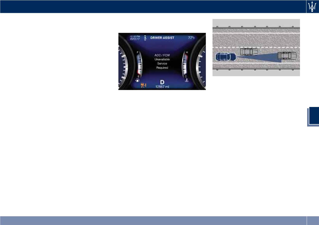
Driving
vehicles or objects in its path this
If the problem persists, contact an
warning may temporarily occur.
Authorized Maserati Dealer.
If weather conditions are not a factor,
the driver should examine the
windshield and the camera. They may
require cleaning or removal of an
obstruction.
When the condition that created
limited functionality is no longer
present, the ACC and FCW systems will
return to full functionality.
Turns and Bends
When driving on a curve with ACC
NOTE:
engaged, the system may decrease the
If the windshield wiper warning
Precautions while Driving with
vehicle speed and acceleration for
message occurs frequently (e.g. more
ACC
stability reasons, with no target
than once on every trip) without any
Offset Driving
vehicle detected. Once the vehicle is
snow, rain, mud, or other obstruction,
ACC may not detect a vehicle in the
out of the curve the system will
5
have the windshield and
same lane that is offset from your
resume your original Set Speed. This is
forward-facing camera inspected at an
direct line of travel, or a vehicle
a part of normal ACC system
Authorized Maserati Dealer.
merging in from a side lane. There
functionality. Moreover, the radar
may not be sufficient distance to the
sensor might detect a vehicle on a
Service ACC/FCW Warning
vehicle ahead. The offset vehicle may
nearby lane or no longer detect the
If the ACC and FCW systems turn off,
move in and out of the line of travel,
target vehicle.
and the system displays a service
which can cause your vehicle to brake
warning, there may be an internal
or accelerate unexpectedly.
system fault or a temporary
malfunction that limits functionality.
Although the vehicle is still driveable
under normal conditions, ACC and
FCW will be temporarily unavailable. If
this occurs, try activating ACC and
FCW again later, following a key cycle.
247
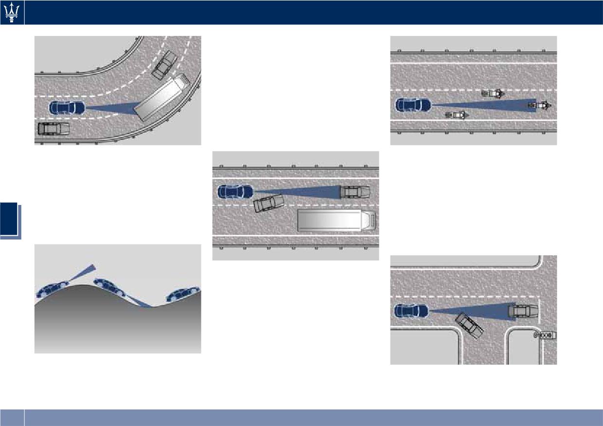
Driving
In the illustration shown, ACC has not
yet detected the vehicle changing lane
and it may not detect the vehicle until
it is too late for the driver to take
action. ACC may not detect a vehicle
until it is completely in the lane. There
may not be sufficient distance to the
lane changing vehicle.
Always be attentive and ready to apply
the brakes if necessary.
Using ACC on Hills
Stationary Objects and Vehicles
When driving on steep hills, ACC may
ACC does not react to stationary
not detect a vehicle in your lane when
objects and stationary vehicles. For
the vehicle reaches the crest.
example, ACC will not react in
Depending on the speed, vehicle load,
situations where the vehicle you are
traffic conditions, and the steepness of
following exits your lane and the
5
the hills, ACC performance may be
vehicle ahead is stopped in your lane.
limited.
Always be attentive and ready to apply
the brakes if necessary.
Narrow Vehicles
Some narrow vehicles (like
motorcycles) traveling near the outer
edges of the lane or edging into the
lane are not detected until they have
moved fully into the lane. There may
not be sufficient distance to the
vehicle ahead.
Lane Changing
ACC may not detect a vehicle until it is
completely in the lane in which you
are traveling.
248
Driving
Radar Device - Compliance
harmful interference in which case the
Forward Collision Warning
Statement
user will be required to correct the
- FCW (optional, with ACC
interference at his own expense.
This device complies with Part 15 of
only)
the FCC Rules (NF3-LRR4).
Radiofrequency Radiation Exposure
Operation is subject to the following
Information
Operation
two conditions:
This equipment complies with FCC
radiation exposure limits set forth for
The Forward Collision Warning (FCW)
• this device may not cause harmful
an uncontrolled environment. This
system with braking action interacts
interference, and
equipment should be installed and
with the Adaptive Cruise Control
• this device must accept any
operated with minimum distance of
(ACC), uses the same parts for sensing
interference received, including
7.8 in (20 cm) between the radiator
vehicle ahead (hereinafter “target
interference that may cause
and your body.
vehicle”) as well as part of the
undesired operation.
This transmitter must not be
warnings/messages on system
Any unauthorized modifications or
co-located or operating in conjunction
condition and activation status. For
changes to these devices could void
with any other antenna or transmitter.
further details, refer to “Adaptive
the authority of the user to operate
Cruise Control - ACC” in this section.
this equipment.
Full performance can be reached only
5
This equipment has been tested and
when both the sensing parts have
found to comply with the limits for a
detected the object, the difference
Class A digital device, pursuant to Part
between full and reduced
15 of the FCC Rules. These limits are
performance is not visible for the
designed to provide reasonable
driver.
protection against harmful
The FCW provides audible and visual
interference when the equipment is
warnings when a potential collision is
operated in a commercial
detected. Brake actuation and limited
environment. This equipment
braking may also be applied
generates, uses, and can radiate radio
depending on the specific scenario.
frequency energy and, if not installed
NOTE:
and used in accordance with the
instruction manual, may cause harmful
FCW system is not intended for
interference to radio communications.
towing: this could lead the system to
Operation of this equipment in a
malfunctions and/or to late reaction.
residential area is likely to cause
249
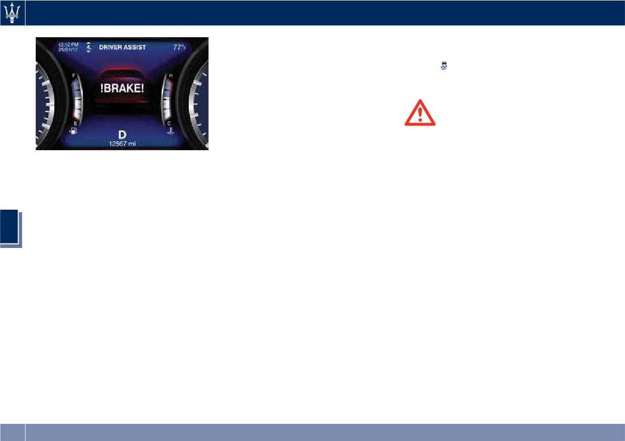
Driving
When the system determines a
actuation too.
collision with the vehicle in front of
• FCW will automatically deactivated
you is no longer probable, the warning
when
(ESC OFF) button is pressed
messages will be deactivated.
(LED light up).
NOTE:
• Bad weather conditions, like heavy
rain, snow, etc., can lead to reduced
WARNING!
system performance. Under these
• Forward Collision Warning (FCW) is
conditions relevant objects will not
not intended to avoid a collision on
be detected or detected late by the
its own, nor can FCW detect every
FCW monitors the information from
system.
type of potential collision. The driver
the forward looking radar sensor as
• FCW is designed to react in specific
well as the Electronic Brake Controller
has the responsibility to avoid a
situations in typical traffic scenarios
(EBC), to calculate the probability of a
collision by controlling the vehicle
with objects in the same lane driving
forward collision. When the system
via braking and steering. Failure to
in the same direction, but under
determines that a forward collision is
follow this warning could lead to
certain conditions it can also react on
serious injury or death. The driver is
5
probable, the driver will be provided
stationary objects in the same lane. It
always in charge to safely drive and
with audible and visual warnings and
is not designed to react to oncoming
to avoid critical situations, and not
may provide a warning brake
traffic or crossing traffic.
rely on the support of the FCW
actuation. If the driver does not take
• The FCW alerts may be triggered to
system. Driver has to keep in mind
actuation based upon these
objects other than vehicles such as
that the system and therefore its
progressive warnings, then the system
guard rails or sign posts based on the
intervention is always subject to the
will provide a limited level of active
course prediction. This is expected
prevailing physical limits.
braking to help slow down the vehicle
and is a part of normal FCW
and mitigate the potential forward
• Forward Collision Warning (FCW) is
activation and functionality.
collision. If the driver reacts to the
not intended either to warn or to
• It is unsafe to test the FCW system.
warnings by braking and the system
apply any brake aid/brake
To prevent such misuse of the system,
determines that the driver intends to
intervention in the event of
after four Active Braking events
avoid the collision by braking but has
collisions with pedestrians or
within a key cycle, the Active Braking
not applied sufficient brake force, the
bicycles.
portion of FCW will be deactivated
system will compensate and provide
until the next key cycle. The limit of
additional brake force as required.
four events applies to the brake
250
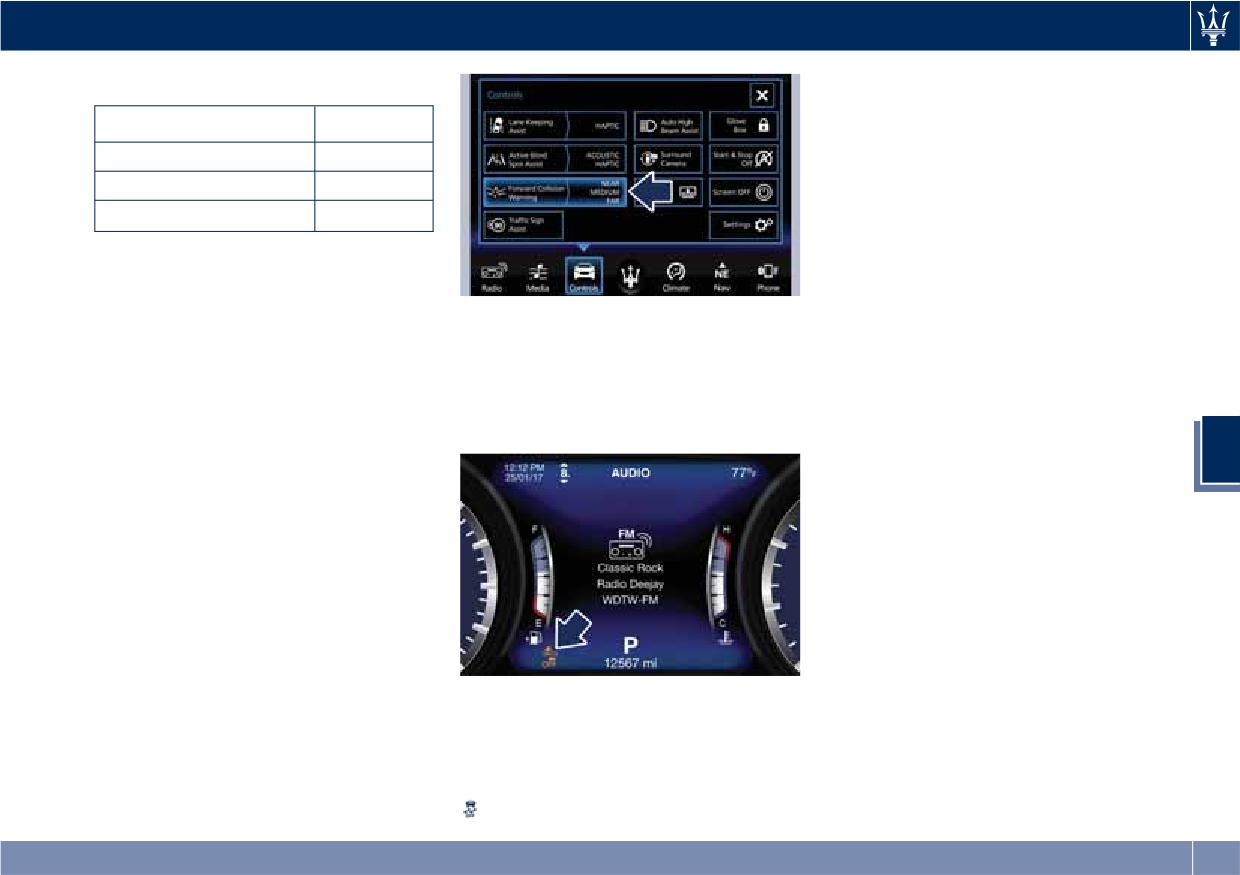
Driving
Speed Range of Use
NOTE:
The FCW system setting is kept in
Speed
mph (km/h)
memory from one key cycle to the
Minimum
0 (0)
next.
Engaged/activated
1.12
(1.8)
Changing FCW Sensitivity and
Maximum
155 (250)
Active Braking
When the speed is outside the
The default status of FCW Sensitivity is
specified limits, the system
the “Medium” setting. When the
automatically disables without turning
active braking function (“Forward
Setting options are described in the
on the corresponding warning light
Collision Warning Active Braking”)
following paragraph.
on the instrument cluster.
setting is on, the system warns you of
When FCW status for some reason
a possible collision with the vehicle in
changes to off, the corresponding
FCW Status
front of you when you are farther
amber warning light on instrument
The driver can adjust FCW sensitivity
away and it applies limited braking.
cluster will light on.
or enable/disable the brake actuation
This gives you the most reaction time
5
with the other emergency brakings by
to avoid a possible collision.
touching "Controls" soft-key on MTC+
Changing the sensitivity status to the
display. The current setting is indicated
“Near” setting, allows the system to
beside to the "Forward Collision
warn you of a possible collision with
Warning" soft-key. If you want to
the vehicle in front of you when you
change the setting, touch the soft-key
are much closer. This setting provides
on the side to enter FCW page.
less reaction time than the “Far”
sensitivity setting, which allows for a
more dynamic driving experience.
“Medium” is the intermediate status
This warning light informs the driver
between the two described above.
that FCW is disabled. This warning
light will light even when the
activation of another driver assistance
feature or drive mode (example:
(ESC OFF)) disables the FCW.
251
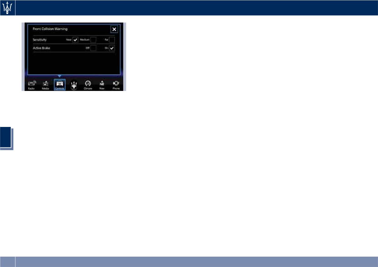
Driving
providing limited autonomous braking
This equipment has been tested and
or additional brake support if the
found to comply with the limits for a
driver is not braking adequately in the
Class A digital device, pursuant to Part
event of a potential frontal collision. In
15 of the FCC Rules. These limits are
this state the system disables the brake
designed to provide reasonable
jerk.
protection against harmful
interference when the equipment is
Limited Operation and Service
operated in a commercial
Warning
environment. This equipment
The messages indicating on display the
generates, uses, and can radiate radio
limited functionality or service at an
frequency energy and, if not installed
NOTE:
Authorized Maserati Dealer required
and used in accordance with the
• The default values shall appear at
are the same as for the ACC system.
instruction manual, may cause harmful
every new ignition cycle: Sensitivity =
For further details, refer to “Adaptive
interference to radio communications.
“Medium” and Active Braking = on.
Cruise Control - ACC” in this section.
Operation of this equipment in a
• FCW may not react to irrelevant
residential area is likely to cause
objects such as objects not in the
Radar Device - Compliance
harmful interference in which case the
5
path of the car, stationary objects
Statement
user will be required to correct the
that are far away, oncoming traffic,
This device complies with Part 15 of
interference at his own expense.
on cross traffic vehicles, or leading
the FCC Rules (NF3-LRR4).
Radiofrequency Radiation Exposure
vehicles with the same or higher rate
Operation is subject to the following
Information
of speed.
two conditions:
This equipment complies with FCC
• The active braking (autonomous
• this device may not cause harmful
radiation exposure limits set forth for
braking/braking aid) will not be
interference, and
an uncontrolled environment. This
provided in case of potential collision
equipment should be installed and
with static object such as guard rails,
• this device must accept any
operated with minimum distance of
walls, etc..).
interference received, including
7.8 in (20 cm) between the radiator
• FCW will be disabled like ACC (refer
interference that may cause
and your body.
to chapter “Adaptive Cruise Control -
undesired operation.
This transmitter must not be
ACC” in this section.
Any unauthorized modifications or
co-located or operating in conjunction
changes to these devices could void
Changing the active braking status to
with any other antenna or transmitter.
the authority of the user to operate
“Off” prevents the system from
this equipment.
252
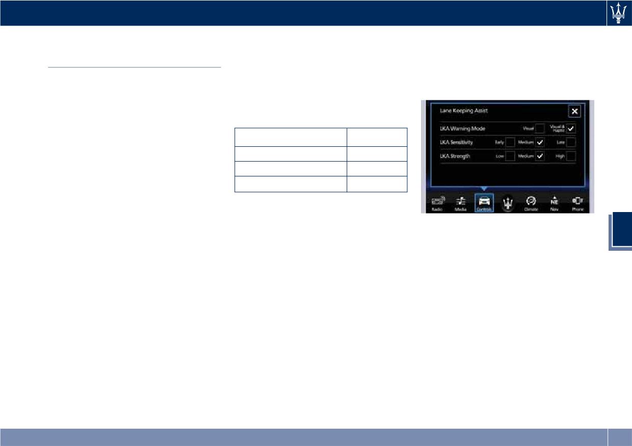
Driving
NOTE:
System response can be set to "Early",
Lane Keeping Assist - LKA
"Medium" (default mode) or "Late".
In case of wet road or raining
(optional, with ACC only)
System reaction force can be set to
conditions the function could be
"Low", "Medium" (default mode) or
This system was designed especially
disabled by the system in order to
"High".
for highway or freeway driving, to
minimize the risks.
reduce the risk that the vehicle, under
particular circumstances, accidentally
Speed Range of Use
departs from the lane in use. When
this happens, graphic instructions on
Speed
mph (km/h)
instrument cluster display together
Minimum
37 (60)
with steering torque application and
Engaged/activated
37 (60)
steering wheel vibration (depending
on the distance to the line) warn the
Maximum
112 (180)
driver that the vehicle is going out of
the lane initiates a steering maneuver
Customized Settings
to try to prevent the lane exit.
Meanings of Settings
LKA is configurable by the driver in
To detect lane lines, the system uses
5
order to maximize its efficiency based
• "Visual" only: the system will not
the forward-facing camera behind the
on the driver driving style and the
request any steering torque/
rear-view mirror, which is the same
expectation of the system, reducing at
vibration to correct the car
one used also by the lighting system
the same time the possible
trajectory. The system will only show
to manage the automatic high beams.
invasiveness.
on the TFT display when the vehicle
The logic core is in the front radar.
Entering "Controls" page on MTC+
is passing the lane.
LKA system remembers the condition
display the driver can see the current
• "Visual & Haptic": the system will
it was in before turning off the
setting beside the "Lane Keeping
apply steering torque when lane
vehicle.
Assist" soft-key.
departure is detected while showing
Refer to “MTC+ "Controls" Screen” in
Touching “Lane Keeping Assist”
at the same time the proper cluster
section “Dashboard Instruments and
soft-key can disable or enable the
indication, adding to this steering
Controls” for further information.
system.
vibration when the departure is very
Touching the soft-key on the side the
imminent.
driver can change the setting.
When "Visual & Haptic" is selected
Driver warnings can be only "Visual"
and LKA is enabled then the following
or "Visual & Haptic" (default mode).
menu will be used by the system.
253
Driving
• "LKA Sensitivity": it tunes the
wheel or with hands off for only a
• With lane boundaries it is mainly
distance to the lane boundary where
limited amount of time. When the
referred to painted lines,
the system will start to apply steering
system is enabled it will trigger cluster
nevertheless the system in good
torque.
warning in case at least one hand is
conditions might properly recognize
• "LKA Strength": it tunes the steering
not detected on the steering wheel.
as valid lane boundaries also other
torque value to have a stronger or
The torque application as well as the
types (for example road edges, curbs,
weaker trajectory correction/
vibration are suppressed/inhibited in
etc..).
deviation.
case of: high driver torque in the
Being this function used to prevent
steering wheel, high lateral
unintentional lane change/lane drift, it
acceleration, hands not on the steering
will be temporary suppressed/inhibited
wheel detected for more than a
WARNING!
by a turn indicator activation,
certain time.
In rare cases, Lane Keeping Assist
therefore, graphic warning, steering
High dynamic driving behaviors,
(LKA) may make an inappropriate
torque application and vibration will
driving on the lane boundary, or
steering torque application. LKA may
be terminated. In this condition in case
driving off course will prevent the
be interrupted at any time counter
of a vehicle detected by the Blind Spot
function from working. FCW braking
steering. Lack of attention may lead to
Assist (BSA) system in the covered area
and stability system interventions (ESC,
5
serious injury or death.
on the proper side, there can be the
ABS) will also prevent the system from
transition from LKA to Active Blind
operating. Changing lanes results in
Spot Assist (ABSA) (if this latter is on
System Availability
system inhibition for a certain time. In
and properly configured).
The ADAS systems (LKA, CC, ACC, FCW
addition, the driver must respect some
and HAS) help the driver while driving.
road characteristics such as
Function Description and
These systems can be set and
minimum-maximum width, lanes
Operating Mode
monitored simultaneously on the
clearly defined by two lane boundaries
The intent of the function is to prevent
display, after opening “Driver Assist”
and, only in limited cases and for a
the lane departure by warning the
menu (see paragraph “TFT Display:
limited time, at least one lane
driver through indication on the
Menus and Settings” under
boundary.
cluster and, if set, applying steering
“Instrument Cluster” in section
NOTE:
torque and vibration. Whenever the
“Dashboard Instruments and
• In case of wet road or raining
system is enabled there will be graphic
Controls”).
conditions the function could be
on the dedicated screen in the driver
LKA is designed for an attentive driver;
disabled by the system in order to
assist page and for the others it will be
therefore the system is available only
minimize the risks.
available in the left top corner of the
when his/her hands are on the steering
254
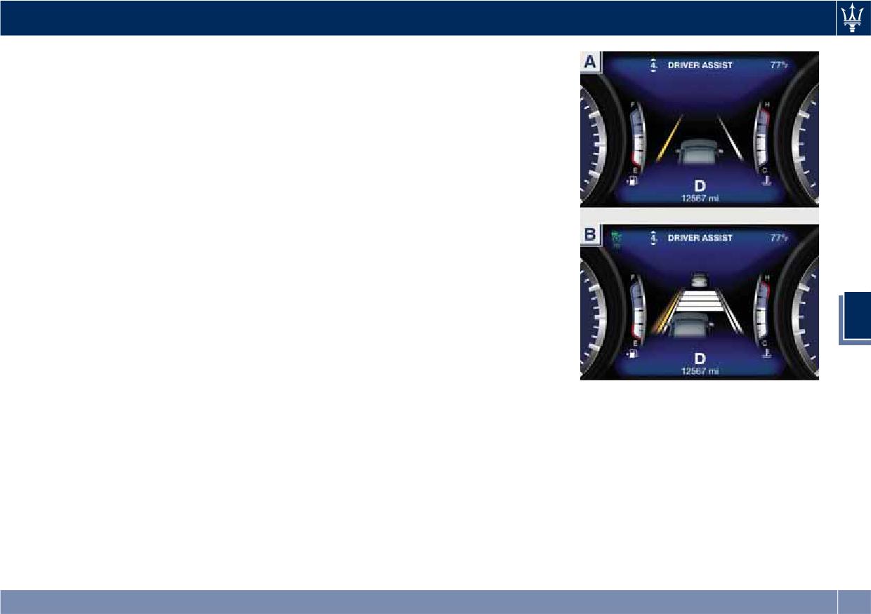
Driving
cluster screen. The graphic which
is detected and the system is capable
intent is to represent at the glance the
to intervene on it.
system knowledge of the lane in front
An example of these screens can be
of the car, the system suppression
found in the following figures:
status and warning.
A: with only LKA system activated,
For this reason, a simple colour code
steering torque in progress to
has been adopted for each line (of the
correct the trajectory towards
two presented):
the lane center;
• Both grey lines means system is
B: with LKA and ACC systems
enabled, not able to operate
activated, car is crossing the lane
(suppression condition present or
boundary, steering torque and
lane detection system not able to
vibration if configured are in
properly estimate the lane);
progress when this graphic is
• Left/right grey line: the lane
shown.
detection system is not able to
detect that specific lane boundary;
5
• Yellow line: there is a steering
torque intervention in progress that
tries to prevent a departure on that
side, in this situation the warning
should increase the driver attention
When in Driver Assist Page
requiring him/her to properly handle
the situation;
• Yellow flashing line: the graphic is
shown whenever the system detects
a very imminent lane departure;
torque and steering vibration can be
added to this warning if configured
by the customer.
The white lines (one or both) indicates
that the corresponding lane boundary
255
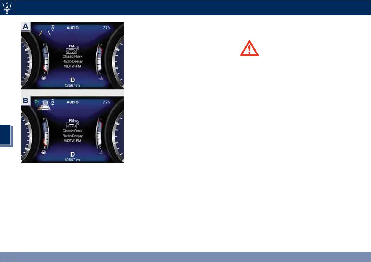
Driving
rain, snow, wet roads, fog, direct sun
prevent/interrupt the system
on the camera, etc.).
intervention.
NOTE:
• The presence of the hands on the
WARNING!
steering wheel is detected by a logic
If the driver fails to adapt his/her
combination of a capacitive sensor
driving style, Lane Keeping Assist
installed in the steering wheel and
(LKA) can neither reduce the risk of an
the measured applied torque at the
accident nor override the laws of
steering column. This leads to a more
physics. It cannot take into account
robust hands detection when hands
road, weather or traffic conditions.
are actually on the steering wheel (at
Active LKA is only an aid. Driver is
least one).
always responsible for the distance to
• The sensors are not able to detect
the vehicle in front, for vehicle speed,
the presence of the hands on the
for braking in good time and for
steering wheel areas covered in
staying in lane.
wood, plastic bezels or carbon inserts
5
(where present).
System in Fault
Sharp turns, slopes and change in
When the LKA cannot properly
slopes, poor lane boundaries, as well
operate due to a fault of its
as construction areas and all the
components or because the windshield
Out of Driver Assist
scenario described in this paragraph
in front of the forward facing camera
The icons that represent the status of
may challenge the system, therefore
is dirty, the amber light and/or the
the ADAS systems remain displayed
be always ready to prevent any
corresponding message will be
even when you exit the "Driver Assist"
unexpected behaviour of the car.
displayed.
screen.
Damaged front bumper, windshield
replaced without proper technical
System Limitations
intervention may also lead to system
Because of physical limits, in order to
malfunction or system unavailability.
properly operate, the system needs
Other conditions such as fault, but not
good visibility (it might not work or
explicitly indicated here may also
not properly operate in case of heavy
256
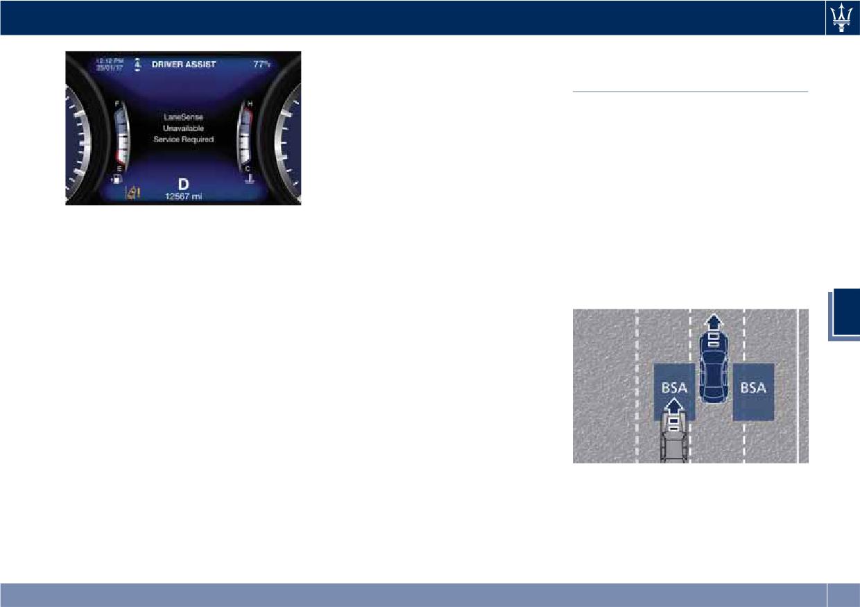
Driving
This equipment has been tested and
Blind Spot Assist (without
found to comply with the limits for a
ACC)
Class A digital device, pursuant to Part
15 of the FCC Rules. These limits are
BSA System Operation
designed to provide reasonable
protection against harmful
The Blind Spot Assist (BSA) system uses
interference when the equipment is
two radar-based sensors, located
operated in a commercial
inside the rear bumper fascia, to
environment. This equipment
detect highway licensable vehicles
generates, uses, and can radiate radio
(cars, buses, motorbikes, etc.) that
frequency energy and, if not installed
enter the blind spot zones from the
If message suggestion does not allow
and used in accordance with the
rear/front/side of the vehicle.
fixing the fault, avoid using the system
instruction manual, may cause harmful
The example shown in the figure
and have the vehicle inspected at an
interference to radio communications.
highlights the blind spots on either
Authorized Maserati Dealer.
Operation of this equipment in a
side of the vehicle when oncoming
Radar Device - Compliance
residential area is likely to cause
traffic is approaching from behind.
Statement
harmful interference in which case the
5
user will be required to correct the
This device complies with Part 15 of
interference at his own expense.
the FCC Rules (NF3-LRR4).
Operation is subject to the following
Radiofrequency Radiation Exposure
two conditions:
Information
This equipment complies with FCC
• this device may not cause harmful
radiation exposure limits set forth for
interference, and
an uncontrolled environment. This
• this device must accept any
equipment should be installed and
interference received, including
operated with minimum distance of
interference that may cause
7.8 in (20 cm) between the radiator
When the vehicle is started, the BSA
undesired operation.
and your body.
warning light will momentarily
Any unauthorized modifications or
This transmitter must not be
illuminate in both outside rear view
changes to these devices could void
co-located or operating in conjunction
mirrors to let the driver know that the
the authority of the user to operate
with any other antenna or transmitter.
system is operational and on. The BSA
this equipment.
system sensors operate when the
257
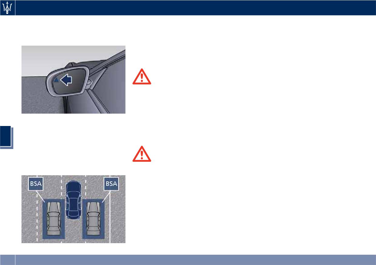
Driving
vehicle is in any forward gear and
The BSA system monitors the detection
• Always pay attention to the traffic
enters standby mode when the
zones on both sides of the vehicle
situation and maintain a safe
transmission is in (P) Park.
when the vehicle speed reaches
distance at the side of the vehicle.
approximately 6 mph (10 km/h) or
higher and will alert the driver of
NOTE:
vehicles in these areas.
If your vehicle has experienced any
damage in the area where the sensor
is located, even if the fascia is not
WARNING!
damaged, the sensor may have
• The BSA system does NOT alert the
become misaligned. Take your vehicle
driver about rapidly approaching
at an Authorized Maserati Dealer to
vehicles that are outside the
verify sensor alignment. Having a
detection zones.
sensor that is misaligned will result in
the BSA not operating to specification.
The BSA detection zone shown in
• The BSA might alert the driver too
figure covers approximately one lane
late especially in case of rapidly
The area on the rear bumper fascia
on both sides of the vehicle
approaching vehicles.
where the radar sensors are located
5
(approximately 11 ft or 3.3 m). The
must remain free of snow, ice, and
blind spot area extends from
dirt/road contamination so that the
immediately behind the exterior
BSA system can function properly. Do
WARNING!
rear-view mirrors up to about 23 ft (7
not cover or block the area of the rear
m) behind the rear bumper.
Risk of accident despite Blind Spot
bumper fascia where the radar sensors
Assist (BSA).
are located with foreign objects
BSA does not detect/react to the
(bumper stickers, spoilers, bicycle racks,
following:
etc.).
• Overtaking vehicles close on the
The BSA system notifies the driver of
side, placing them in the blind spot
vehicles or objects in the detection
area. As a result, BSA may neither
zones by illuminating the BSA warning
give warnings nor intervene in such
light located in the outside mirrors in
situations.
addition to sounding an audible
(chime) alert and reducing the radio
volume (if the radio is on). Refer to
258
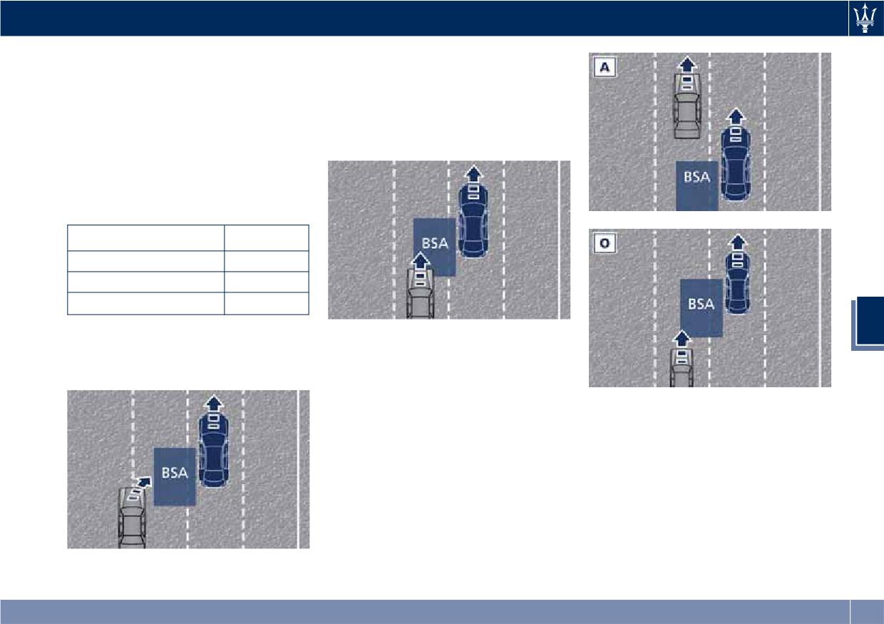
Driving
“BSA and RCP Setting” in this chapter
Entering from the Rear
for further information.
The alert will turn on when the
The BSA system monitors the
vehicles that come up from behind
detection zone from three different
your vehicle on either side and enter
entry points (side, rear, overtaking
the rear detection zone with a relative
traffic) while driving to see if an alert
speed of more than 27 mph (43 km/h).
is necessary. The BSA system will issue
an alert whenever a vehicle enters any
one detection zone as outlined below.
Speed Range of Use
Speed
mph (km/h)
Minimum
6 (10)
Engaged/activated
6 (10)
Maximum
- (-)
5
Entering from the Side
Overtaking Traffic
Vehicles that move into your adjacent
The figures show the vehicle
lanes from either side of the vehicle.
approaching (A) and passing (O)
another vehicle in the overtaking lane.
If you pass another vehicle slowly, the
Other Cases
vehicle remains in the blind spot for
The BSA system is not designed to
approximately 2 seconds, the BSA
issue an alert on stationary objects
warning light in the outside mirror
such as guardrails, posts, walls, foliage
will illuminate after 1.5 seconds.
heaps, berms, etc. However,
If the difference in speed between the
occasionally the system may alert on
two vehicles is greater, the warning
such objects. This is normal operation
light will not illuminate.
and your vehicle does not require
service.
259
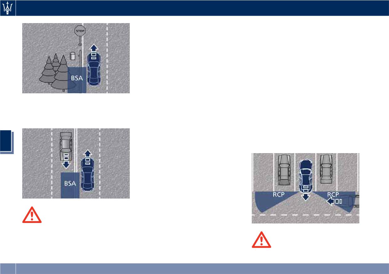
Driving
• The BSA system is not designed to
NOTE:
detect pedestrians, cyclists, or
In a parking lot situation, oncoming
animals.
vehicles can be obscured by vehicles
• Even if your vehicle is equipped with
parked on either side. If the sensors
the BSA system, always check your
are blocked by other structures or
vehicle’s outside and rear-view
vehicles, the system will not be able to
mirrors for any vehicles approaching
alert the driver.
from behind or overtaking.
Proceed slowly and cautiously out of
• Use your turn signal before changing
the parking space until the rear end of
lanes.
the vehicle is moderately exposed.
The BSA system will not alert you of
The RCP system will then have a clear
objects that are traveling in the
RCP - Rear Cross Path
view of the cross traffic. If an
opposite direction of the vehicle in
oncoming vehicle is detected, the RCP
adjacent lanes.
The Rear Cross Path (RCP) feature is
system will alert the driver using both
intended to aid the drivers when gear
the visual and audible alarms. If the
in reverse of parking spaces where
radio is on, it will also reduce the radio
5
their vision of oncoming vehicles may
volume.
be blocked.
The RCP system monitors the rear
detection zones on both sides of the
vehicle. Using sensors located on either
side of the rear bumper, it detects any
vehicles or objects that are moving
toward the side of the vehicle with a
minimum speed of approximately 1 to
2 mph (1 km/h to 3 km/h) to a
maximum of approximately 10 mph
WARNING!
(16 km/h), such as in parking lot
• The BSA system is only an aid to
situations.
help detect vehicles in the blind spot
zones.
WARNING!
RCP is not a Back Up Aid system. More
260
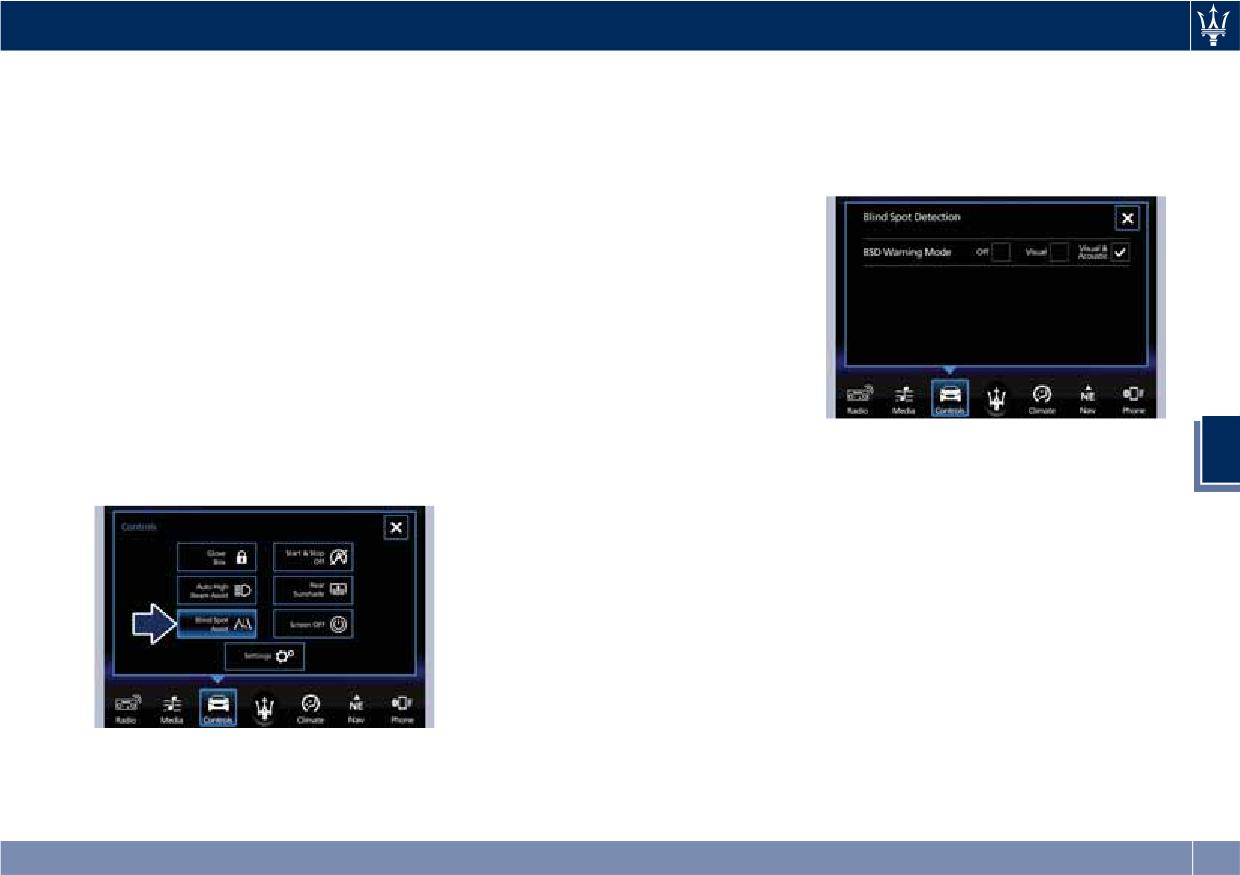
Driving
specifically, it is intended to be used
BSA in Visual Mode
same side at the same time, both the
to help a driver detect an oncoming
visual and audio alerts will be issued.
When operating in “Visual” mode, the
vehicle in a parking lot situation.
In addition to the audible alert, the
BSA system will provide a visual alert
Drivers must be careful when backing
radio volume will be reduced (if the
in the appropriate side view mirror
up, even when using RCP. Always
radio is on).
when it detects a vehicle or an object
check carefully behind your vehicle,
in the detection areas monitored by its
look behind you, and be sure to check
sensors: depending on the status of
for pedestrians, animals, other
the relative turn indicator, the
vehicles, obstructions, and blind spots
warning light can be fixed or flashing.
before backing up. Failure to do so
However, when the system is
can result in serious injury or death.
operating in RCP mode, it will respond
with both visual and audible alerts
BSA and RCP Setting
when an oncoming vehicle or an
object approaching the rear end side
Setting modes can be selected from
of the vehicle is detected.
the MTC+ System.
Whenever an audible alert is
Touch “Controls” soft-key and then
NOTE:
requested, the radio is muted (if the
5
“Blind Spot Assist” soft-key to enter
If the hazard flashers are on, the BSA
radio is on).
the setting page.
system will issue the appropriate visual
BSA in Visual and Acoustic Mode
alert only.
When operating in “Visual & Acoustic”
When the system is in RCP mode, the
mode, the BSA system will provide a
system shall respond with both visual
visual alert in the appropriate side
and audible alerts when a detected
view mirror based on a detected
vehicle or object is present. Whenever
vehicle or object.
an audible alert is requested, the radio
If the turn signal is then activated, and
(if on) is also muted.
it corresponds to an alert present on
Right/left turn/hazard signal status is
that side of the vehicle, an audible
ignored; the RCP status always
chime will also be sounded: in the
requests the chime.
same moment the warning light will
Refer to chapter “MTC+ “Controls”
start flashing.
Blind Spot Assist Off
Screen” in section “Dashboard
Instruments and Controls” for further
Whenever a turn signal and detected
When this function is turned off from
information.
vehicle or object are present on the
the MTC+, there will be no visual or
261
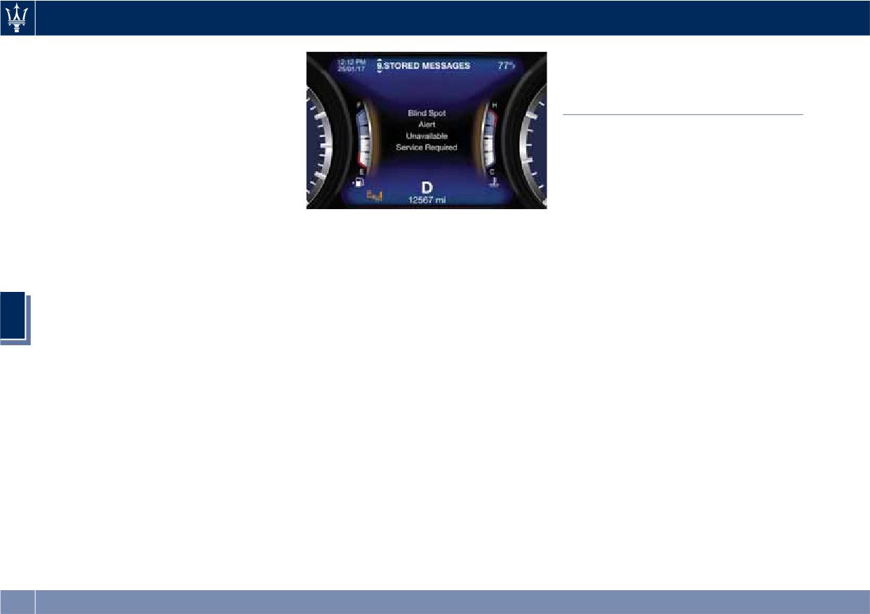
Driving
audible alerts from either the BSA or
Active Blind Spot Assist -
RCP subsystems.
ABSA (optional, with ACC
NOTE:
only)
The BSA system will store the current
operating mode when the vehicle is
ABSA system is only available on
shut off. Each time the vehicle is
vehicles equipped with ACC system
started, the previously-stored mode
and represents an addition to the BSA
will be recalled and used.
previously described (see chapter
"Blind Spot Assist - BSA" of this
System Temporarily Unavailable
section).
In these cases avoid using the system
ABSA adds to the BSA the possibility in
The blind spot system will become
and have the vehicle inspected at an
certain circumstances to avoid and or
temporarily unavailable and the
Authorized Maserati Dealer.
mitigate side collisions with vehicles
instrument cluster display will show
proceeding in the adjacent lanes by
the message “Blind Spot Assist
Radar Device - Compliance
changing the car trajectory in order to
Temporarily Unavailable” when the
Statement
try to keep it inside the detected/
vehicle enters a radio quite zone
5
This device complies with Part 15 of
estimated lane. A steering wheel
(example the areas around radio
the FCC Rules (OAY-SRR3B).
vibration is used as further feedback to
telescopes).
Operation is subject to the following
warn the driver that the lane change is
The warning light on the outside
two conditions:
not safe.
rear-view mirrors will be lit up and stay
• this device may not cause harmful
The main logic core is the front radar,
lit until the vehicle exits the zone.
interference, and
whereas the sense inputs are the
System is Faulty
radars on the rear bumper fascia used
• this device must accept any
The BSA system cannot properly
for sensing the presence of vehicle in
interference received, including
operate due to a fault of its
the blind spot areas and the forward
interference that may cause
components, or because the area on
facing camera placed behind the
undesired operation.
the rear bumper fascia where the
internal rear-view mirror that instead
radar sensors are located is dirty. In
is used for lane detection and
these cases the amber warning light
estimation.
and the related message will be
ABSA is designed to help the driver to
displayed on the instrument cluster.
avoid mitigate a collision. Torque and
vibration application is however
262
Driving
available in the 37 - 112 mph (60 -
Highly dynamic behaviours, driving on
Speed Range of Use
180 km/h) speed interval. All the speed
the lane boundary, off course will
thresholds related to the BSA remain
prevent the function from working.
Speed
mph (km/h)
still valid, since ABSA as mentioned is
FCW braking and stability system
Minimum
37 (60)
BSA extension.
interventions (ESC, ABS) will also
Engaged/activated
37 (60)
ABSA is intended as a “hands-on”
prevent the system from operating.
Maximum
112 (180)
function meaning that the driver is
Changing lane results in system
required to stay engaged in the
inhibition for a certain time.
driving all the time with his/her hands
In addition the road must respect
System Limitation
on the steering wheel, in case hands
some characteristics such as minimum-
Because of physical limits the system
are not on the steering wheel for a
maximum width, lane clearly defined
to properly operate needs good
certain time there cannot be any
by two lane boundaries and only in
visibility (it might not work or not
steering torque application vibration
limited case for a limited time at least
properly operate in case of heavy rain,
included.
one.
snow, wet roads, fog, direct sun on
System Availability
NOTE:
the camera, dirty windshield, low
• In case of wet road or raining
illumination etc.)
ABSA is designed for an attentive
Sharp turns, slopes and change in
5
driver therefore the system is available
conditions the function could be
slopes, poor lane boundaries, as well
only when his/her hands are on the
disabled by the system in order to
as construction areas and all the
steering wheel or with hands off for a
minimize the risks.
scenarios described in this paragraph
very limited amount of time. When
• With lane boundaries it is mainly
may challenge the system, therefore
the system is enabled, it will trigger
referred to painted lines,
be always ready to prevent any
cluster warning in case at least one
nevertheless the system in good
unexpected behaviour of the car.
hand is not detected on the steering
conditions might properly recognise
Damaged front bumper, windshield
wheel.
as valid lane boundaries also other
replaced without proper technical
The torque application as well as the
types (for example road edges,
intervention may also lead to system
vibration are suppressed/inhibited in
curbs, etc..).
malfunction or system unavailability.
case of: high driver torque in the
Other conditions such as faults, but
steering wheel, high lateral
not explicitly indicated here may also
acceleration, hands not on the
prevent/interrupt the system
steering wheel detected for more than
intervention.
a certain time.
263
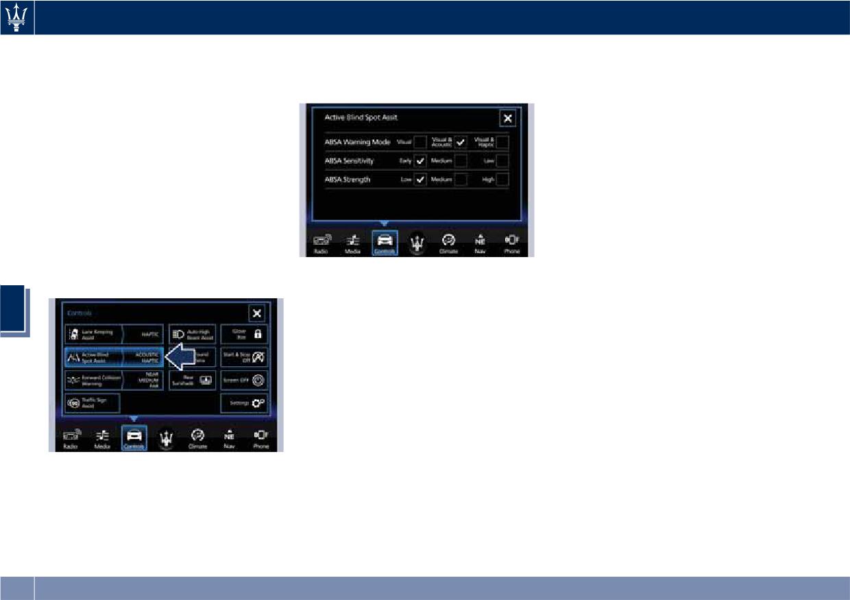
Driving
ABSA Setting
System reaction force can be set to
stronger or weaker trajectory
"Low", "Medium" (default mode) or
correction/deviation.
ABSA is configurable by the customer
"High".
in order to maximize its efficiency
Blind Spot Assist in "Visual & Haptic"
based on the driver driving style and
Mode
his/her expectation of the system,
When the system is on and configured
reducing at the same time the possible
“Visual & Haptic” then the ABSA is
invasiveness.
enabled and to the conventional visual
Setting modes can be selected from
warnings is added the steering torque
the MTC+ System (see "MTC+
and vibration.
"Controls" Screen" in section
When operating in this mode, the
"Dashboard Instruments and Controls"
system will provide a visual alert in the
for further information).
appropriate outside rear-view mirror
Touch "Controls" soft-key to display
when it detects a vehicle or an object
the current status of the ABSA system,
NOTE:
in the detection areas monitored by its
if it was in the on state.
sensors. In case of turn indicator
The ABSA system will store the current
activation on the appropriate side, the
operating mode when the vehicle is
5
system will react with a torque on the
shut off. Each time the vehicle is
steering wheel to try to prevent the
started, the previously-stored mode
lane change and therefore to
will be recalled and used.
avoid/mitigate the collision. The
torque on the steering is applied when
Meanings of Settings
the car is very close to the lane
When "Visual & Haptic" is selected and
boundary as a further feedback to
of course ABSA is enabled, then two
warn the driver of the unsafe
following menus will be used by the
maneuver.
system.
To change status, touch the "Active
NOTE:
• "ABSA Sensitivity": it tunes the
Blind Spot Assist" soft-key.
• The steering torque is not supplied if
distance to the lane boundary where
To change the system setting, touch
the system is not able to estimate a
the system will start to apply steering
the soft-key on the side.
lane and if the turn indicator from
torque.
Driver warnings can be only "Visual",
the appropriate side is not inserted.
• "ABSA Strength": it tunes the
"Visual & Acoustic" (default mode) or
steering torque value to have a
"Visual & Haptic".
264
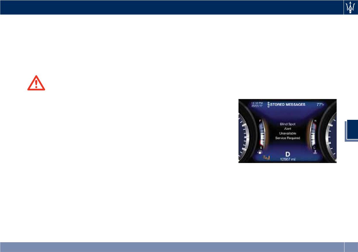
Driving
• The presence of the hands on the
RCP - Rear Cross Path
System Faulty
steering wheel is detected by a logic
Operation
The ABSA system cannot properly
combination of a capacitive sensor
RCP operation is the same as described
operate either due to a fault of its
installed in the steering wheel and
in chapter "Blind Spot Assist - BSA".
components, or because the area on
the measured applied torque at the
When ABSA is turned off from MTC+
windshield where the forward-facing
steering column. This leads to a
"Controls" page, there will be no
camera is located or on the rear
more robust hands detection.
visual or audible alerts from RCP
bumper fascia where the radar sensors
subsystem.
are located is dirty. In these cases the
When ABSA is turned on with any
amber warning light and the related
setting,RCP subsystem shall respond
message will be displayed on the
WARNING!
with both visual and audible alerts
instrument cluster.
• Risk of accident despite steering
when a detected vehicle or object is
torque application of Active Blind
present. Whenever an audible alert is
Spot Assist (ABSA).
requested, the radio (if on) is also
• A course-correcting steering torque
muted.
application cannot always prevent a
Right/left turn/hazard signal status is
collision.
5
ignored; the RCP status always
• The driver is always required to
requests the chime.
steer, brake or accelerate themself,
especially if ABSA warns or makes a
System Temporarily
course correcting steer intervention.
Unavailable
• Always maintain a safe distance at
The blind spot system will become
In these cases avoid using the system
the sides.
temporarily unavailable and the
and have the vehicle inspected at an
• In rare cases, the system may make
instrument cluster display will show
Authorized Maserati Dealer.
an inappropriate steering torque
the message “Blind Spot Assist
application. This application may be
Temporarily Unavailable” when the
Radar Device - Compliance
interrupted at any time by counter
vehicle enters a radio quite zone
Statement
steering.
(example the areas around radio
This device complies with Part 15 of
telescopes).
• Lack of attention may lead to
the FCC Rules (OAY-SRR3B).
The warning light on the outside
serious injury or death.
Operation is subject to the following
rear-view mirrors will be lit up and
two conditions:
stay lit until the vehicle exits the zone.
265
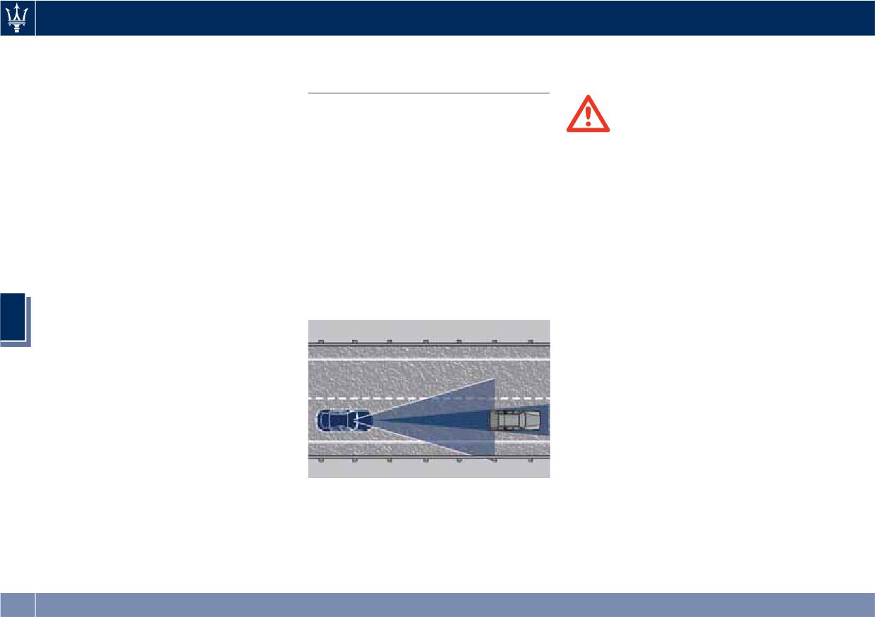
Driving
• this device may not cause harmful
vibrate and a graphic will display on
Highway Assist - HAS
interference, and
the instrument cluster.
(optional, with ACC only)
• this device must accept any
interference received, including
The Highway Assist (HAS) is a level 2
interference that may cause
Autonomy system (in reference to
WARNING!
undesired operation.
NHTSA standards) that is designed to
• In case the vehicle approaches a
aid the driver in the steering,
curve that is too tight in relation to
acceleration, and braking functions of
the current speed the system will
the vehicle.
disengage, therefore the driver must
HAS is designed to only function on
be prepared to take over control of
highways or limited access freeways.
the vehicle immediately at any time.
HAS centers the vehicle by controlling
To avoid this situation it is important
the EPS system based off of lane line
that the vehicle speed is not set
information from the forward-facing
higher than the current speed limit
camera and data from the front radar
of the road.
sensor.
• Highway Assist (HAS) is a hands-on
5
feature! You must keep your hands
on the steering wheel at all times.
The HAS system will disengage and
ACC will cancel if your hands are
removed from the steering wheels
for a set amount of time.
• HAS is intended for use only on
highways or limited access freeways
with a fully attentive driver. When
using HAS, hold the steering wheel
HAS combines ACC and LKA to
and be aware of surrounding traffic
manage the steering and speed of the
and road conditions. Always be
vehicle under specific conditions. The
prepared to immediately take over
conditions to engage HAS are listed in
control of the vehicle from the HAS
the next paragraph. If a lane line cross
system. Failure to follow these
is imminent, the steering wheel will
266
Driving
instructions could result in serious
• Wet roads, roads covered or partially
• Vehicle speed must be between 0 to
injury or death.
covered by snow.
87 mph (0 and 140 km/h).
• The following list does not fully
• Construction zones.
• No faults in the forward facing
represent all situations in which HAS
camera, radar, EPS, or MTC+.
HAS Operation
may not function as intended. Do
• Lane width between 3 to 4.6 yd (2.8
NOT solely rely on the HAS system
With ACC set (see “Adaptive Cruise
and 4.2 m).
to control the vehicle. It is the
Crontrol - ACC” in this section), HAS
• Turn signal not activated.
driver’s responsibility to stay alert
system activates by simply pressing the
• No faults related to this system.
and safely control the vehicle at all
button on the steering wheel.
times.
Once the conditions are met, HAS will
Speed Range of Use
engage.
• If the windshield is replaced, you
Speed
mph (km/h)
must have the forward-facing
camera remounted and aligned by
Minimum
0 (0)
CAUTION!
an Authorized Maserati Dealer.
Engaged/activated
0 (0)
The Highway Assist (HAS) system may
(with ACC engaged)
Many factors can impact the
take up to 5 seconds to engage once
performance of HAS causing the
all conditions are met.
Engaged/activated
18 (30)
5
system to be unable to function as
(with ACC not
The conditions for HAS to engage are
intended. These include (but are not
engaged)
as follows:
limited to):
Maximum
90 (145)
• HAS must be turned on or enabled.
• Narrow, winding or curvy roads.
• Poor visibility (due to heavy rain,
NOTE:
• If set above the maximum speed,
snow, fog, etc.).
In case of wet road or raining
HAS will not function after the
vehicle speed will reach the
• Bright light (oncoming headlights or
conditions the function could be
maximum speed.
direct sunlight) or shadows.
disabled by the system in order to
minimize the risks.
• If set below the maximum speed and
• Damage or obstruction caused by
the ACC target speed is increased,
mud, ice, snow, etc.
• The vehicle must be on the highway
HAS will function up to the
• A damaged or misaligned bumper.
or limited access freeway.
maximum speed and then the system
• Interference from other equipment
• Adaptive Cruise Control (ACC) must
will turn off automatically.
that generates electromagnetic
be engaged.
• When the ACC target speed is
waves.
• Left and right visible lane lines.
reduce and speed is lower than the
267
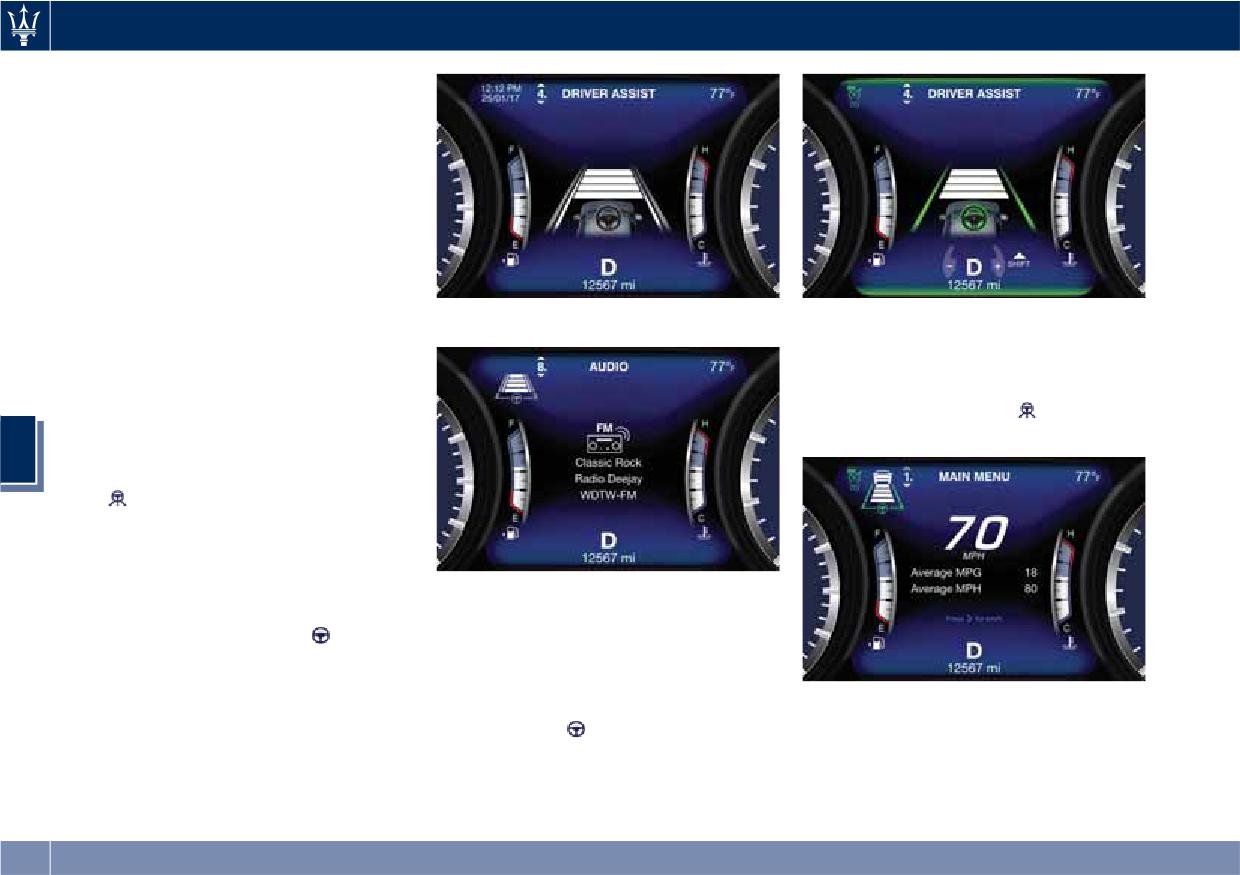
Driving
maximum speed, the system will start
automatically.
• If the ACC target speed is set under
the maximum speed, HAS is active
and vehicle speed increases above
the maximum speed due to slope,
HAS will continue to function.
HAS Monitoring on Instrument
Cluster
HAS and the other ADAS systems
When in Driver Assist Page
When in Driver Assist Page
conditions can be monitored on
When exiting the “Driver Assist” page,
instrument cluster display by accessing
the attention level colour will always
the “Driver Assist” page with the
be displayed until the system is
buttons on the steering wheel (see
disabled by pressing the
button on
“Instrument Cluster” in section
the steering wheel.
5
“Dashboard Instruments and
Controls”).
The
symbol in grey indicates that
the HAS system is active, but not
engaged and is shown at the centre of
the TFT display when the “Driver
Assist” page is displayed. When exiting
Out of Driver Assist Page
the "Driver Assist" page, on TFT
In addition to these symbols, on the
display top left corner, the
grey
TFT top and bottom edge a coloured
symbol will appear in the multiple
glow may appear (further referred to
light of active ADAS systems.
as "attention level colour"). Attention
Out of Driver Assist Page
level colour together with the outline
of the symbol
represent a further
The HAS system uses sensors in the
indication of the system status.
steering wheel outer crown to detect
if the driver’s hands are on the
steering wheel. If the driver’s hands
are not detected on the steering
268
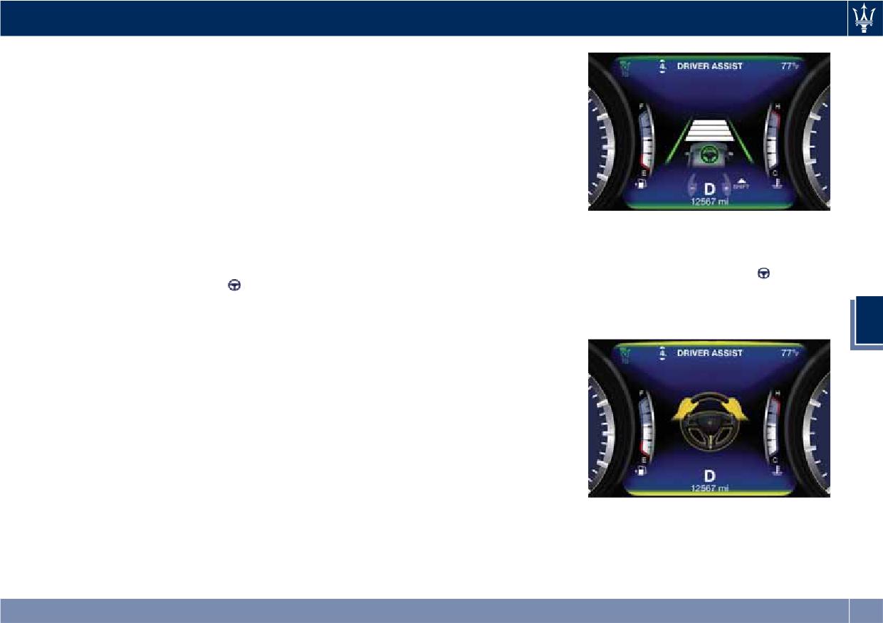
Driving
wheel, the instrument cluster will
In order to be able to use the HAS
display a series of warnings to alert
system, place your hands around the
the driver to return their hands to the
steering wheel outer crown.
steering wheel. There will also be
NOTE:
audible chimes. After a set amount of
time, HAS will cancel if the driver’s
• The presence of the hands on the
hands are not returned to the steering
steering wheel is detected by a logic
wheel.
combination of a capacitive sensor
When the system does not sense the
installed in the steering wheel and
hands on the steering wheel for a few
the measured applied torque at the
seconds (3 - 5 seconds) or more (up to
steering column. This leads to a
The yellow attention level colour
10 seconds), it tries to draw the
more robust hands detection when
appears when the driver removes
attention of the driver by showing,
hands are actually on the steering
his/her hands from the steering wheel
even when the display is not in the
wheel (at least one).
for 3 to 5 seconds and the
symbol
"Driver Assist" page, the
symbol
• The sensors are not able to detect
with the figure of the hands will
with the figure of the hands in the
the presence of the hands on the
occupy the whole central area of the
centre of the display. According to
steering wheel areas covered in
display.
5
such time frames, the system will
wood, plastic bezels or carbon
change the attention level colour,
inserts (where present).
silence the audio in the vehicle (if it is
HAS is deactivated if the steering
active) and emit audible chimes to
wheel is no longer being touched.
invite the driver to take the control of
the vehicle again. This is the only way
System Statuses
to reengage the system.
The active status of the HAS system is
Hands Detection on Steering
indicated by the green attention level
Wheel
colour which is maintained even if the
driver releases his/her grip from the
The sensors in the steering wheel
steering wheel up to 3 seconds.
outer crown are able to detect the
When in Driver Assist Page
presence of the hands on the steering
wheel.
269
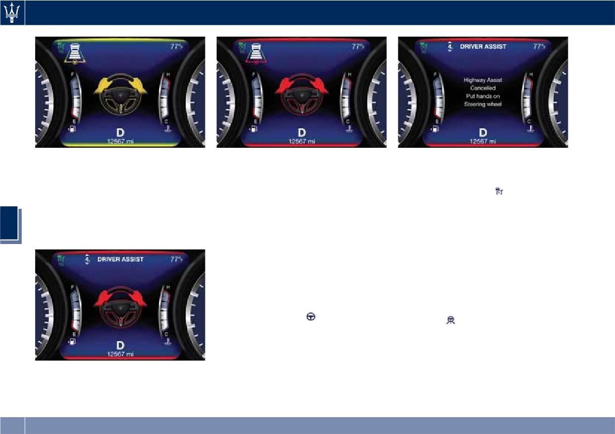
Driving
Out of Driver Assist Page
Out of Driver Assist Page
If the driver keeps his/her hands away
The red attention level colour appears
The red attention level colour remains
from the steering wheel (for more
when the driver releases his/her grip
even when the steering wheel is
than 8 to 10 seconds), also the ACC
from the steering wheel for 5 and up
released for more than 8 to 10
system is deactivated (
white ACC
to 10 seconds: in this case a single
seconds. In this case, if you are
symbol on the display) and will have to
audible chime is repeated until he/she
travelling at a speed above 25 mph
be reset. The aid of LKA system will be
5
will take the control of the vehicle
(40 km/h) a sequences of 3 audible
disabled as well. In these cases the
again.
chimes will be emitted after 8 seconds
display will not show the attention
and a message will inform the driver
level colour anymore and the vehicle
that the HAS system has been
will be controlled by the driver only.
disengaged, inviting him/her to grip
HAS Disengage
the steering wheel again. The same
will happen after 10 seconds if you
To disengage HAS you can do any of
travel at a speed below 25 mph
the following actions:
(40 km/h). Then the
symbol on TFT
• Press the
HAS enable button on
display will become grey.
the steering wheel.
• Begin steering manually.
• Press brake pedal.
When in Driver Assist Page
• Turn off ACC.
• Unbuckle the driver’s seat belt.
270
Driving
• Press ACC Gap button for two
• The presence of the hands on the
prepared to take over control of the
seconds to enable CC system.
steering wheel is detected by a logic
vehicle immediately at any time.
• Shift out of the (D) Drive gear.
combination of a capacitive sensor
installed in the steering wheel and
Radar Device - Compliance
• Enter an Autonomous Emergency
the measured applied torque at the
Braking (AEB) event (See chapter
Statement
steering column. This leads to a
"Forward Collision Warning - FCW"
This device complies with Part 15 of
more robust hands detection.
in this section).
the FCC Rules (NF3-LRR4).
• Turn signal activated.
Operation is subject to the following
System Limitations
two conditions:
System Cancellation
HAS is unable to guide the vehicle
• this device may not cause harmful
The HAS system will cancel (without
when the following conditions occur.
interference, and
driver intervention) if either of the
• Lane markings are not clear or
• this device must accept any
following actions occur:
visibility is poor (i.e. heavy rain,
interference received, including
• Curve that is too tight.
snow, fog, etc.).
interference that may cause
• When leaving the grip of the hands
• Obstructed, covered or damaged
undesired operation.
on the steering wheel.
forward-facing camera or sensor.
Any unauthorized modifications or
5
• Vehicle exits the highway or limited
• When driving on hills or sharp
changes to these devices could void
access freeway.
curves.
the authority of the user to operate
this equipment.
• Lane line markers aren’t detected by
• When approaching toll booths.
This equipment has been tested and
the forward facing camera.
• When the highway entrance or exit
found to comply with the limits for a
• Any ADAS system faults.
is wider than 20 ft (6 meters).
Class A digital device, pursuant to Part
• ACC cancellation.
• Bright light (ex. direct sunlight or
15 of the FCC Rules. These limits are
• Vehicle speed exceeds the maximum
glare) facing the forward camera.
designed to provide reasonable
limit.
protection against harmful
• Lateral accelerations exceeds the
interference when the equipment is
limits.
WARNING!
operated in a commercial
Many unforeseen conditions can occur
environment. This equipment
NOTE:
that can affect the performance of
generates, uses, and can radiate radio
• When HAS cancels, the
symbol
Highway Assist (HAS). Always keep
frequency energy and, if not installed
will turn red then grey.
this in mind and drive attentively. Be
and used in accordance with the
instruction manual, may cause harmful
271
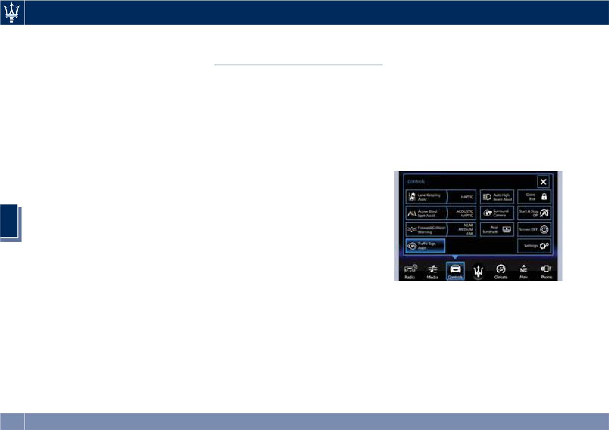
Driving
interference to radio communications.
• The performance of TSA depends on
Traffic Sign Assist - TSA
Operation of this equipment in a
the update degree of navigation
(optional)
residential area is likely to cause
system’s maps.
harmful interference in which case the
TSA detects traffic signs through the
user will be required to correct the
use of a forward-facing digital camera
Setting and Signs Monitoring
interference at his own expense.
mounted on windshield, behind the
on Instrument Cluster
Radiofrequency Radiation Exposure
rear-view mirror. TSA assists the driver
To set TSA feature touch “Controls”
Information
by displaying on the instrument cluster
soft-key on MTC+ display and then
This equipment complies with FCC
detected speed limits and traffic signs
“Traffic Sign Assist” soft-key. The blue
radiation exposure limits set forth for
with a restriction indicated by an
color of the soft-key outline will
an uncontrolled environment. This
additional sign (e.g. in snow
indicate that the feature is set.
equipment should be installed and
conditions). TSA also uses the data of
operated with minimum distance of
the navigation system, in order to
7.8 in (20 cm) between the radiator
provide information to the driver in all
and your body.
cases in which the camera is not able
This transmitter must not be
to detect the traffic signs that are
5
co-located or operating in conjunction
present on the road where the car is
with any other antenna or transmitter.
travelling.
Some examples of these are: due to
low visibility, light reflection, damaged
traffic signs, traffic signs in wrong
position like rotated or fallen poles.
Touch the soft-key again to turn off
NOTE:
TSA feature.
• Overtaking restriction signs are not
If TSA feature is set and a sign or a
displayed by the TSA system.
speed limit is detected, the related
• TSA provides a visual warning to the
icons are displayed in the upper area
driver when he/she unintentionally
of the instrument cluster beside of the
exceeds the maximum speed allowed
main menu number and scroll arrows.
by 2 mph - km/h.
The display area is divided in two
different sectors:
272
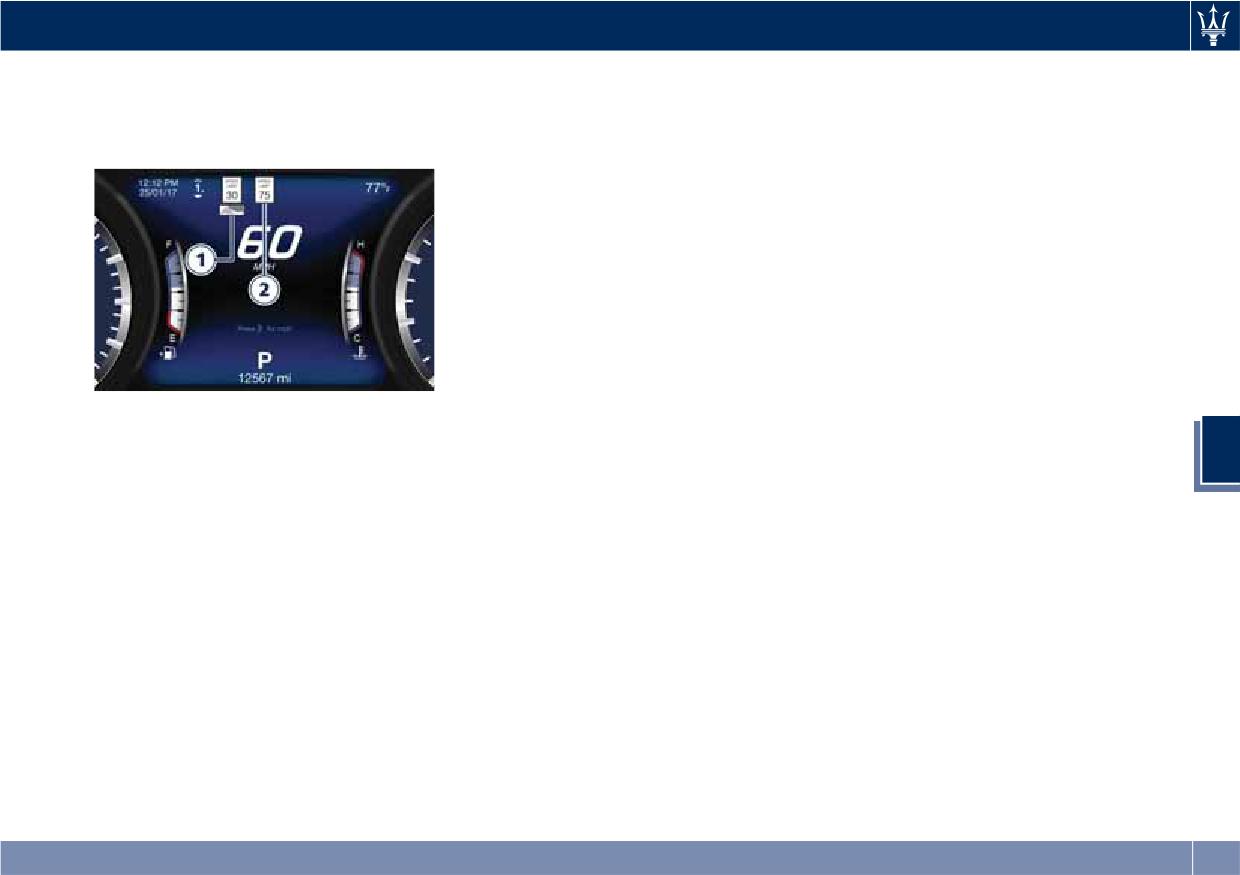
Driving
Since TSA also uses the data provided
• If the signs are ambiguous, e.g.
1 Conditioned speed limit area.
by the navigation system, it can
traffic signs on construction sites or
2 Unconditioned speed limit area.
update the sector 2 of the display in
in adjacent lanes.
the following situations without
detecting traffic signs:
• When the vehicle changes road.
• Highway enter/exit.
• Urban area stored in the digital map
enter/exit.
System Limitations
TSA may be impaired or may not
function in the following situations:
• If there is poor visibility, e.g. due to
NOTE:
insufficient illumination of the road,
Overtaking restriction signs are not
if there are highly variable shade
5
displayed by the TSA system.
conditions or in rain, snow or fog.
When the visual warning is provided
• If there is glare, e.g. from oncoming
only the unconditioned speed limit (in
traffic, direct sunlight or reflections
sector 2) will start blinking if the
from other vehicles.
vehicle speed is greater than 1 mph
• If the windshield in the area of the
- km/h. If the vehicle speed stays above
camera is dirty, or if the camera is
the unconditioned speed limit of
fogged up, damaged or covered.
1 mph - km/h for several seconds the
• If the traffic signs are hard to detect,
unconditioned speed limit sign will
e.g. due to dirt or snow, or because
stop blinking because the maneuver is
they are covered or because of
evaluated as intentional. If the TSA is
insufficient lighting.
not able to determine any kind of
• If the information in the navigation
valid speed limit neither from camera
system's digital map is incorrect or
nor from digital maps the following
out-of-date.
image will be shown in sector 2.
273
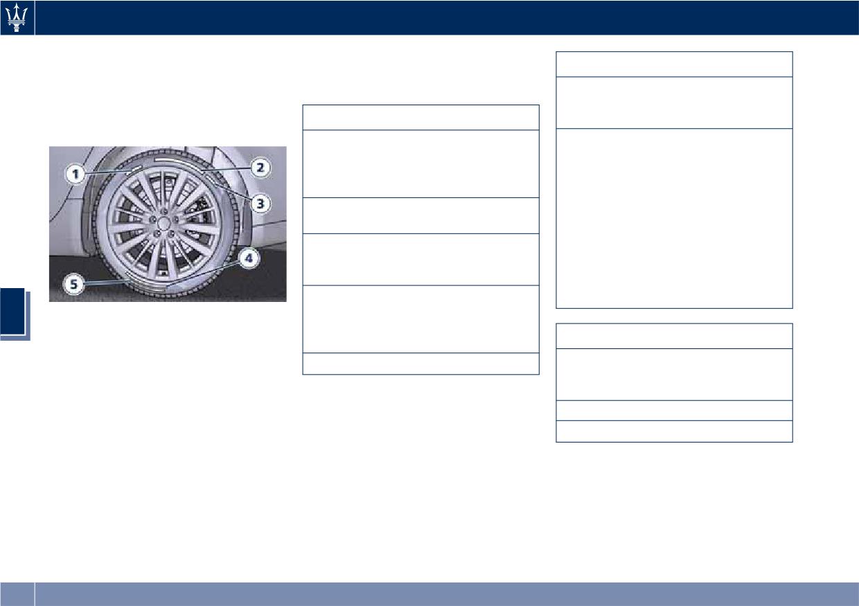
Driving
Tire Sizing Chart
Tires - General Information
Service Description:
EXAMPLE: P265/50 ZR19 (100Y) XL or
100 = Load Index - A numerical
Tire Safety Information
265/50 ZR19 (Y100) XL
code associated with the maximum
Tire Markings
Size Designation:
load a tire can carry
P = Passenger car tire size based on
Y = Speed Symbol - A symbol
U.S. design standards
indicating the range of speeds at
“...blank...” = Passenger car tire
which a tire can carry a load
based on European design standards
corresponding to its load index
under certain operating conditions.
265 = Section width in millimeters
The maximum speed corresponding
(mm)
to the speed symbol should only be
50 = Aspect ratio in percent (%) -
achieved under specified operating
Ratio of section height to section
conditions (i.e., tire pressure, vehicle
width of tire
loading, road conditions, and posted
ZR = Construction Code
speed limits)
• Z: means a tire usable at speeds
5
1. U.S. DOT Safety Standards Code
greater than 150 mph (240 km/h)
(TIN).
• R: means radial construction
Load Identification:
2. Size Designation.
19 = Rim diameter in inches (in)
“...blank...” = Absence of any text on
the sidewall of the tire indicates a
3. Service Description.
Standard Load (SL) tire
4. Maximum Pressure and Maximum
XL = Extra Load (or reinforced) tire
Load.
LL = Light Load tire
5. Treadwear, Traction and
Temperature Grades (see
“Department of Transportation
Uniform Tire Quality Grades” in
this section).
274
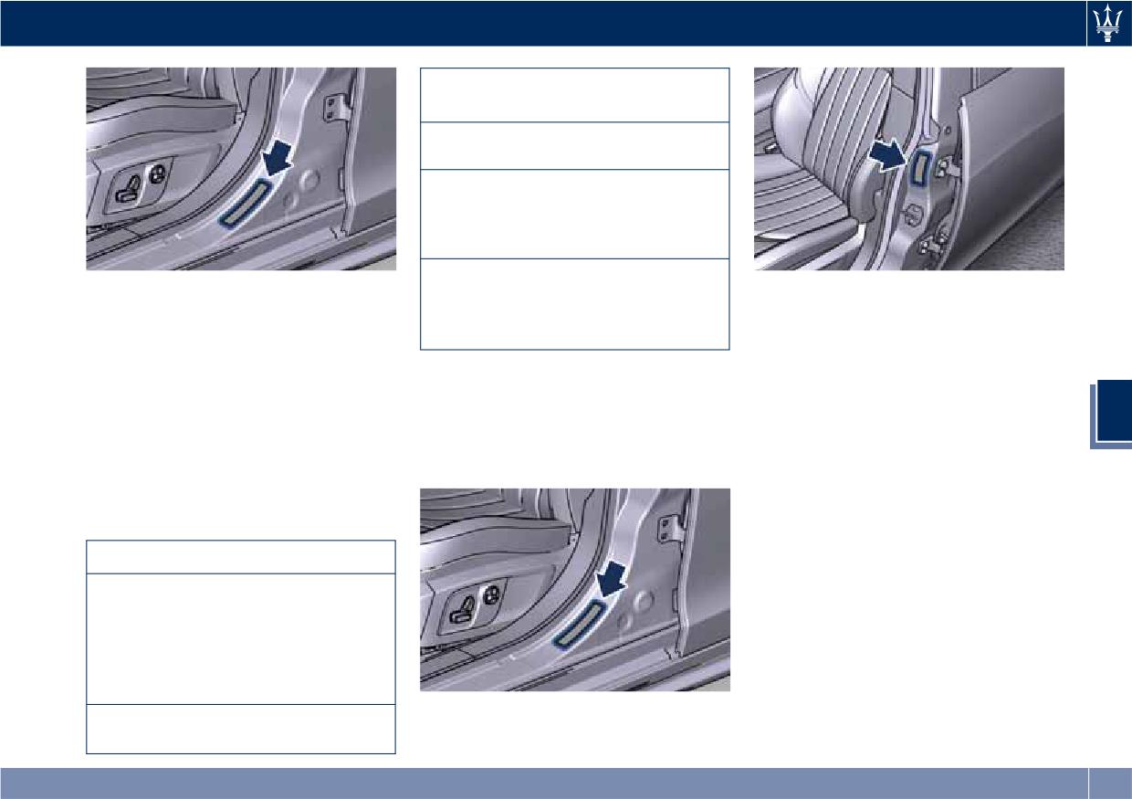
Driving
L9 = Code representing the tire size
(two digits).
ABCD = Code used by the tire
manufacturer (one to four digits).
03 = Number representing the week
in which the tire was manufactured
(two digits). In this case, 03 means
the 3rd week.
13 = Number representing the year
Tire Identification Number (TIN)
in which the tire was manufactured
Loading Information Label
(two digits). In this case, 13 means
This label tells you important
The TIN may be found on one or both
the year 2013.
information about the:
sides of the tire, however the date
code may only be on one side. Tires
• Cold tire inflation pressures for the
with white sidewalls will have the full
Tire and Loading Information Label
front, rear, and spare tires.
TIN, including the date code, located
The proper cold tire inflation pressure
• Number of people that can be
5
on the white sidewall side of the tire.
and the loading information are listed
carried in the vehicle.
Look for the TIN on the outboard side
in two labels on the driver's side rear
• Total weight the vehicle can carry.
of black sidewall tires as mounted on
door pillar.
• Tire size designed for the vehicle.
the vehicle. If the TIN is not found on
the outboard side, then you will find it
Loading
on the inboard side of the tire.
The vehicle maximum load on the tire
must not exceed the load carrying
EXAMPLE: DOT MA L9 ABCD 0313
capacity of the tire on your vehicle.
DOT = Department of Transportation
You will not exceed the tire's load
- This symbol certifies that the tire
carrying capacity if you adhere to the
is in compliance with the U.S.
loading conditions, tire size, and cold
Department of Transportation tire
tire inflation pressures specified on
safety standards and is approved for
the “Tire and Loading Information
highway use.
Label” and in the “Features and
Tire Information Label
MA = Code representing the tire
Specifications” section.
manufacturing location (two digits).
275
Driving
NOTE:
Department of Transportation
grades represent the tire's ability to
Under a maximum loaded vehicle
Uniform Tire Quality Grades
stop on wet pavement, as measured
under controlled conditions on
condition, gross axle weight ratings
The following tire grading categories
specified government test surfaces of
(GAWRs) for the front and rear axles
were established by the National
asphalt and concrete. A tire marked C
must not be exceeded.
Highway Traffic Safety Administration.
may have poor traction performance.
The specific grade rating assigned by
Tires
the tire's manufacturer in each
Driving over rough or damaged road
category is shown on the sidewall of
surfaces, as well as debris, curbs and
WARNING!
the tires on your vehicle.
other obstacles can cause serious
The traction grade assigned to this tire
All passenger car tires must conform to
damage to wheels, tires, and
is based on straight-ahead braking
Federal safety requirements in
suspension parts.
traction tests, and does not include
addition to these grades.
This is more likely to occur with
acceleration, cornering, hydroplaning,
low-profile tires, which provide less
Treadwear
or peak traction characteristics.
cushioning between the wheel and the
The Treadwear grade is a comparative
road.
rating, based on the wear rate of the
Temperature Grades
5
Be careful to avoid road hazards and
tire when tested under controlled
The temperature grades are A (the
reduce your speed, especially if your
conditions on a specified government
highest), B, and C, representing the
vehicle is equipped with low profile
test course. For example, a tire graded
tire's resistance to the generation of
tires.
150 would wear one and one-half
heat and its ability to dissipate heat,
times as well on the government
when tested under controlled
course as a tire graded 100. The
conditions on a specified indoor
WARNING!
relative performance of tires depends
laboratory test wheel. Sustained high
upon the actual conditions of their
Overloading of your tires is
temperature can cause the material of
use, however, and may depart
dangerous. Overloading can cause tire
the tire to degenerate and reduce tire
significantly from the norm due to
failure, affect vehicle handling, and
life, and excessive temperature can
variations in driving habits, service
increase the stopping distance. Use
lead to sudden tire failure. The grade
practices, and differences in road
tires of the recommended load
C corresponds to a level of
characteristics and climate.
capacity for your vehicle. Never
performance, which all passenger car
overload them.
Traction Grades
tires must meet under the Federal
Motor Vehicle Safety Standard No.
The Traction grades, from highest to
109. Grades B and A represent higher
lowest, are AAA, A, B, and C. These
276
Driving
levels of performance on the
Safety
tread life resulting in a need for
laboratory test wheel, than the
earlier tire replacement. Under-
minimum required by law.
inflation also increases tire rolling
resistance resulting in higher fuel
WARNING!
consumption.
• Improperly inflated tires can be
WARNING!
dangerous.
Ride comfort and vehicle stability
The temperature grade for this tire is
Proper tire inflation contributes to a
• Under-inflation increases tire flexing
established for a tire that is properly
comfortable ride. Over-inflation
and can result in tire overheating.
inflated and not overloaded.
produces a jarring and uncomfortable
• Over-inflation reduces a tire's ability
Excessive speed, under-inflation, or
ride.
to cushion shock. Objects on the
excessive loading, either separately or
road and potholes can cause
Tire Pressure Checkup
in combination, can cause heat
damage that results in tire failure.
buildup and possible tire failure.
The proper cold tire inflation pressure
• Over-inflated or under-inflated tires
is indicated on the driver's side rear
can affect vehicle handling and can
Tire Pressure
door pillar and on the table “Tire
fail suddenly, resulting in loss of
Inflation Pressure” in section
Proper tire inflation pressure is
vehicle control.
“Features and Specifications”.
5
essential for safety and best
• Unequal tire pressures can cause
Inflation pressure specified on the
performance of your vehicle. The tire
steering problems.
table always refers to “cold tire
pressure monitoring system “TPMS”
inflation pressure”. Cold tire inflation
• Unequal tire pressures from one side
setup on the vehicle (see “Tire
pressure is defined as the tire pressure
of the vehicle to the other can cause
Pressure Monitoring System” in this
after the vehicle has not been driven
the vehicle to drift to the right or
section) may alert the driver about
for at least three hours, or driven less
left.
insufficient tire pressure even though
than 1 mi (1.6 km) after a three hour
the driver is responsible for regularly
• Always drive with each tire inflated
period.
checking the tire pressure.
to the recommended cold tire
Check tire pressures more often in
Radial tires fitted on the vehicle may
inflation pressure.
case of significant outside
look properly inflated even when they
temperature changes, as tire pressure
actually are under inflated. Do not
Economy
varies according to temperature
make a visual judgment when
Improper inflation pressures may
changes.
determining proper inflation.
cause uneven wear patterns to
The pressure should be checked and if
Three primary driving aspects are
develop across the tire tread. These
necessary adjusted; tire wear and
affected by improper tire pressure:
abnormal wear patterns will reduce
277
Driving
overall conditions should also be
When the tread is worn to one of the
Replacement Tires
checked monthly. Tire pressures
tread wear indicators, the tire should
NOTE:
change by approximately 1 PSI (0.07
be replaced.
bar) per 12°F (7°C) of air temperature
In order to maintain high performance
change. Keep this in mind when
and safety level under all driving
checking tire pressure inside a garage,
conditions, Maserati strongly
WARNING!
especially in winter.
recommends to use tires equivalent to
The wet performance (aquaplaning
Example: If garage temperature = 68°F
the originals in size, quality and
resistance) will decrease
(20°C) and the outside temperature =
performance when replacement is
proportionally to the thickness of the
32°F (0°C) then the cold tire inflation
needed.
tread.
pressure should be increased by 3 PSI
(0.21 bar) for every 12°F (7°C) for this
For the size designation of your tire
Tires Durability
outside temperature condition.
see the label on the driver's side rear
Tire pressure may increase from 2 to 6
The service life of a tire depends on
door pillar or see table “Wheels” in
PSI (0.13 to 0.4 bar) during operation.
various factors including, but not
section “Features and Specifications”.
DO NOT reduce this normal pressure
limited to:
The “Load Index” and “Speed Symbol”
build-up or your tire pressure will be
for your tire will be found on the
5
• driving style;
too low. After inspecting or adjusting
original equipment tire sidewall.
• tire pressure;
the tire pressure, always reinstall the
• distance driven.
NOTE:
valve stem cap. This will prevent
Maserati recommends Maserati Genuine
moisture and dirt from entering the
Tires marked with “MGT” logo
valve stem, which could damage the
valve stem and the TPMS sensor
WARNING!
specifically designed for its models.
connected to it.
Tires and the spare tire (if equipped)
It is recommended to replace the two
should be replaced after six years,
front tires or two rear tires as a pair.
Tread Wear Indicators
regardless of the remaining tread.
Replacing just one tire can seriously
Tread wear indicators are in the
Failure to follow this warning could
affect your vehicle’s handling.
original equipment tires to help you
result in tire failure.
If you ever replace a wheel assembly,
determine when your tires should be
make sure that the wheel’s
replaced.
specifications (valve, TPMS sensor and
These indicators are molded into the
tire) match those of the original
bottom of the tread grooves.
wheels. Failure to use equivalent
replacement tires may adversely affect
278
Driving
the safety, handling, and ride of your
• Never exceed the maximum speed
“Technical Data” and “Tire Inflation
vehicle.
rating of the tires. Risk of accident
Pressure” chapters in section “Features
Your Authorized Maserati Dealer is
and serious personal injury due to
and Specifications”.
available to provide suggestions as to
excessive speed.
the types of tires most suited to the
• Failure to equip your vehicle with
use foreseen by the Customer.
tires having adequate speed
WARNING!
capability can result in tire failure.
The standard tires profile and rubber
mixture are optimized for wet and dry
WARNING!
driving conditions. Standard tires may
• Do not use a tire, wheel size or
CAUTION!
not prove favorable for snow
rating other than that specified for
conditions.
Replacing original tires with tires of a
your vehicle. Some combinations of
different size may result in false
unapproved tires and wheels may
NOTE:
speedometer and odometer readings.
change suspension dimensions and
Snow tires should have the same load
performance characteristics,
Winter Tires
capacity as original equipment tires
resulting in altered steering,
and should be mounted on all four
handling, and braking operations of
These tires are specially designed for
5
wheels.
the vehicle. This can cause
driving on snow and ice and are fitted
unpredictable handling and stress to
to replace the ones supplied with the
Snow Chains
steering and suspension
vehicle. Winter or all-season tires can
components. Use only the tire and
be identified by the M+S (Mud &
Maserati approved traction devices (or
wheel sizes with load ratings
Snow) or 3PMSF (3 Peaks Mountain
snow chains) may be used to improve
appointed for your vehicle.
Snow Flake) designation on the tire
traction on compacted snow in heavy
sidewall.
snow conditions.
• Never use a tire with a smaller load
Before mounting winter tires, contact
The use of snow chains is specified by
index or capacity, other than what
an Authorized Maserati Dealer to
local regulations of each country.
was originally equipped on your
receive the technical information
Use snow chains of reduced
vehicle. Using a tire with a smaller
necessary to advise you on wheel and
dimensions, with a maximum
load index could result in tire
tire compatibility.
projection of 0.23 in (6 mm) beyond
overloading and failure.
As to the type of tires to use, inflation
the tire tread.
• Always check the maximum speed
pressures and winter tires
The chains may be fitted only on 18”
rating on the tire sidewall on any
specifications, carefully follow the
and 19” rear wheel tires.
tire on the vehicle.
indications as reported in the
279
Driving
Please contact an Authorized Maserati
NOTE:
Tire Pressure Monitoring
Dealer for further information.
The Authorized Maserati Dealer can
System (TPMS)
Check the snow chain tension after
provide you with all information about
driving for a distance of about 55 yd
the Maserati Snow Chains, available in
The Tire Pressure Monitoring System
(50 m) with the chains fitted.
the "Genuine Accessories" range.
(TPMS) will warn the driver of a low
With the snow chains fitted, it is
tire pressure according to the vehicle
advisable to deactivate the ESC system
Compact Spare Tire
recommended cold pressure indicated
(see chapter “Drive Mode” in this
on the table “Tire Inflation Pressure”
section).
The limited-use spare tire, or compact
in section “Features and
spare tire, is for temporary emergency
Specifications” and on the label
use only.
applied on the driver's side rear door
CAUTION!
This tire is identified by a label indicating
pillar.
the driving speed limitations to comply
• The use of non-recommended snow
Tire pressure should always be set
with when using the spare tire.
chains may damage the vehicle.
based on cold inflation tire pressure.
Inflate the spare tire to the cold
• Broken snow chains can cause serious
The cold tire inflation pressure must
inflation pressure listed on the table
damage. Stop the vehicle
not exceed the maximum inflation
“Tire Inflation Pressure” in section
5
immediately if noise occurs that
pressure molded into the tire sidewall.
“Features and Specifications”.
could indicate snow chain breakage.
Check “Tires - General Information” in
Mounting the spare tire affects vehicle
Remove the damaged parts of the
section “Driving” for information on
handling. Replace (or repair) as soon as
snow chain before further use.
how to properly inflate the tires.
possible the original equipment tire
The tire pressure will also increase as
• Do not exceed 30 mph (50 km/h).
and reinstall it on the vehicle. Do not
the vehicle is driven - this is normal
• Drive cautiously and avoid severe
install more than one compact spare
and there is no adjustment required
turns and large bumps, especially
tire and wheel on the vehicle at a
when this occurs.
with a loaded vehicle.
time.
The TPMS will warn the driver of a low
• Avoid holes in the road, do not drive
tire pressure if the tire pressure falls
over steps or sidewalks and do not
below the low-pressure warning limit
drive on long stretches without
WARNING!
for any reason, including low
snow. This will prevent damage to
With these compact spare tires, do not
temperature effects and natural
the vehicle and the roadbed.
drive more than 50 mph (80 km/h).
pressure loss of the tire.
Temporary use spares have limited
The TPMS will continue to warn the
tread life.
driver of low tire pressure as long as
the condition persists and will not turn
280
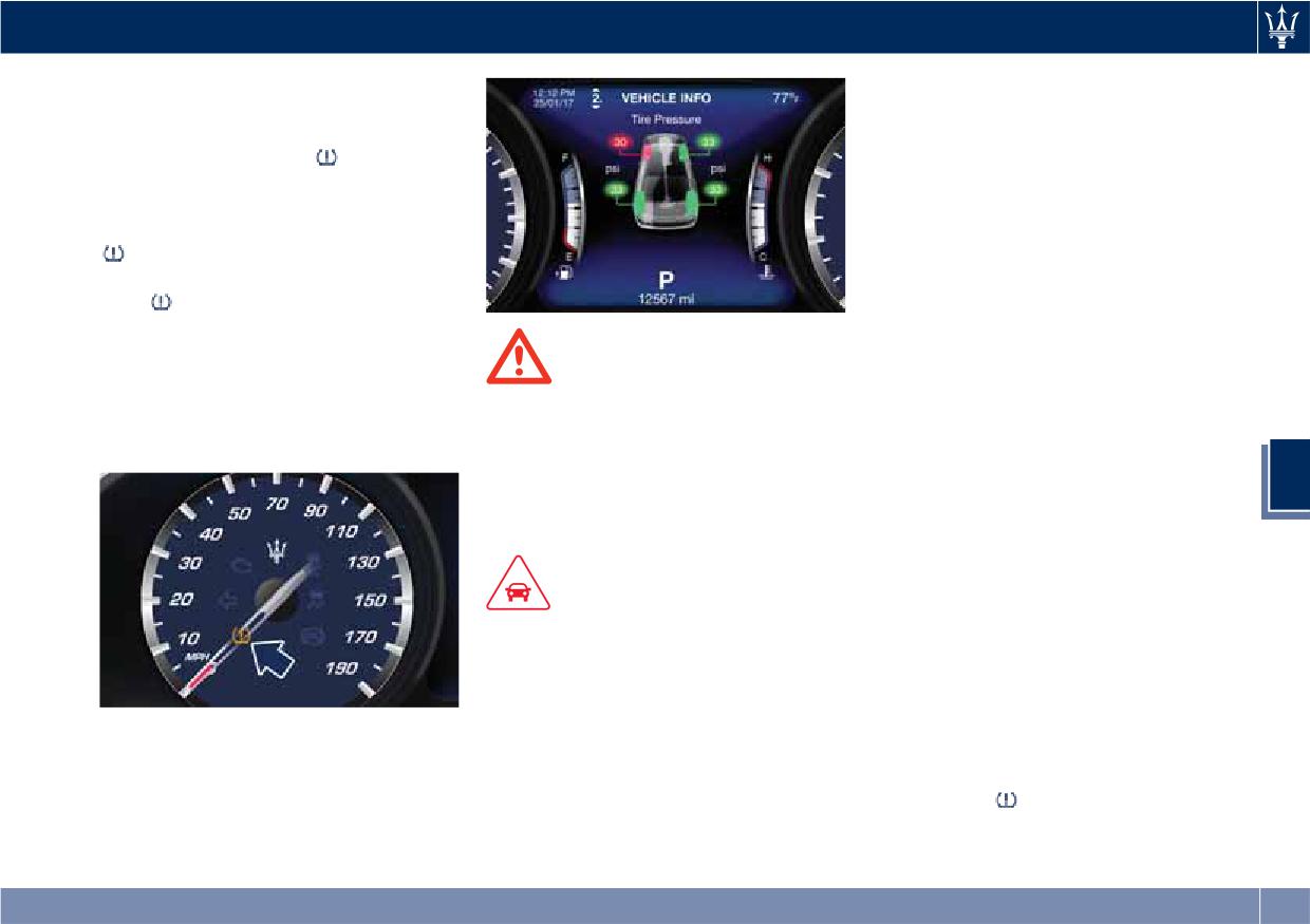
Driving
off until the tire pressure is equal or
Do not use aftermarket tire sealants
above the recommended cold
or balance beads if your vehicle is
inflation pressure. Once the low tire
equipped with a TPMS, as damage
to the sensors may result.
pressure warning light
illuminates,
you must increase the tire pressure to
• The system can temporarily
experience radio-electric
the recommended cold inflation
interference emitted by devices
pressure in order for the TPMS light
using similar frequencies.
to turn off. The system will
• After inspecting or adjusting the tire
automatically update and the TPMS
pressure, always reinstall the valve
light
will turn off once the system
stem cap. This will prevent moisture
acquires the correct tire pressure.
and dirt from entering the valve
The vehicle may need to be driven for
stem and damage the TPMS internal
up to 20 minutes above 15 mph
WARNING!
sensor.
(24 km/h) in order for the TPMS to
The TPMS warns the driver that the
acquire and process the updated
tire pressure has decreased. This
NOTE:
setting.
warning does not exempt the driver
• Driving on a significantly
from periodically checking the tires
underinflated tire causes the tire to
5
and from complying with the
overheat and may lead to tire
prescribed tire pressure levels.
failure. Under-inflation also reduces
fuel efficiency and tire tread life, and
may affect the vehicle’s handling and
CAUTION!
stopping ability.
• The TPMS has been optimized for
• The TPMS is not a substitute for
the original equipment tires and
proper tire maintenance, and it is
wheels. TPMS pressures and
the driver’s responsibility to maintain
warning have been established for
correct tire pressure using an
the tire size equipped on your
accurate tire pressure gage, even if
vehicle. Undesirable system
under-inflation has not reached the
operation or sensor damage may
level to trigger illumination of the
occur when using replacement
equipment that is not of the same
TPMS light
size, type, and/or style. Aftermarket
(Continued)
wheels can cause sensor damage.
281
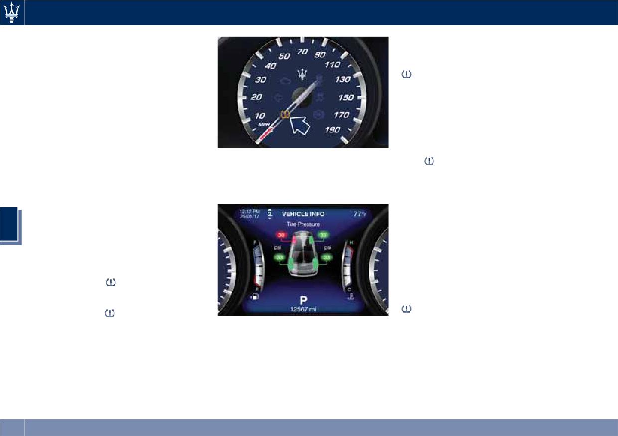
Driving
(Continued)
automatically update, the graphic
• Seasonal temperature changes will
display in the instrument cluster will
affect tire pressure, and the TPMS
stop flashing, and the TPMS light
will monitor the actual tire pressure
will turn off. The vehicle may need
in the tire.
to be driven for up to 20 minutes
above 15 mph (24 km/h) in order for
Premium System
the TPMS to acquire and process the
updated information.
The TPMS system uses wireless
technology with wheel rim mounted
Tire Pressure System Fault
electronic sensors to monitor tire
If a system fault is detected, the TPMS
pressure levels. Sensors mounted to
The instrument cluster will also display
light
will flash for 75 seconds and
each wheel as part of the valve stem
a screenshot reporting the pressure
then remain lit followed by a beeping
transmit tire pressure readings to the
values of each tire with flashing low
sound. Therewith, the instrument
receiver module.
pressure value.
cluster will display a "Service Tire
The TPMS consists of the following
Pressure System" message for a
components:
minimum of five seconds and then
5
• receiver module;
display dashes (--) in place of the
pressure value to indicate which sensor
• four TPMS sensors;
is ineffective.
• various TPMS messages, which
If the ignition switch is cycled, the
display on the instrument cluster;
sequence will repeat, in case the
• warning light
system fault still persists. If the system
Tire Pressure Low Warning
fault no longer exists, the TPMS light
will no longer flash, and the
The TPMS light
will illuminate in
"Service Tire Pressure System" message
the instrument cluster and an acoustic
Should this occur, you should stop as
will no longer be displayed, and a
signal will notify that tire pressure is
soon as possible and inflate the tire/s
pressure value will be displayed in
low in one or more of the four tires.
with the low pressure (the one/s
place of the dashes.
flashing in the instrument cluster
A system fault can occur due to any of
graphic) to the recommended cold
the following:
pressure inflation value. Once the
system receives the updated tire
• Signal interference due to electronic
pressure value, the system will
devices or driving next to facilities
282
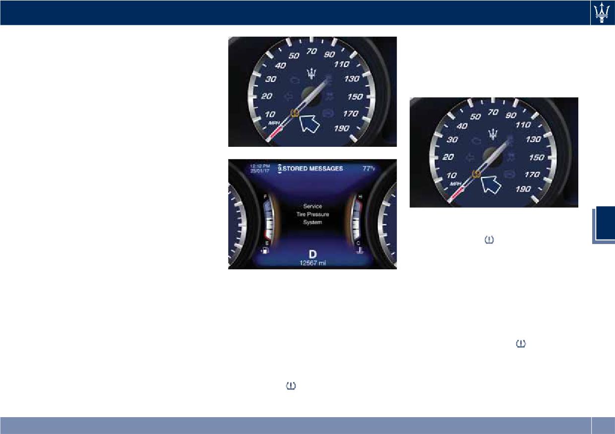
Driving
emitting the same radio frequencies
addition, the graphic in the
as the TPMS sensors.
instrument cluster will still display a
• Installing aftermarket window
flashing pressure value
tinting that contains materials that
corresponding to the compact tire
may block radio wave signals.
position.
• Accumulation of snow or ice around
the wheels or wheel housings.
• Using tire chains on the vehicle.
• Using wheels/tires not equipped
with TPMS sensors.
The instrument cluster will also display
a "Service Tire Pressure System"
message for a minimum of five
seconds when a system fault related to
an incorrect sensor location fault is
detected. In this case, the "Service Tire
• After driving the vehicle for up to 20
5
Pressure System" message is then
minutes above 15 mph (24 km/h),
followed by a graphic display with
the TPMS light
will flash for 75
pressure values still shown. This
seconds and then remain lit. The
indicates that the pressure values are
instrument cluster will then display a
still being received from the TPMS
"Service Tire Pressure System"
Vehicles with Compact Spare Tire
sensors but they may not be located in
message for a minimum of five
• The compact spare tire does not
the correct vehicle position. The
seconds and then display dashes (--)
have a TPMS sensor. Therefore, the
system still needs to be serviced as
in place of the pressure value.
TPMS will not monitor the pressure
long as the "Service Tire Pressure
• Each subsequent ignition switch
of the compact spare tire.
System" message is displayed.
cycle will be followed by a beeping
• If you replace a tire having pressure
sound, the TPMS light
will flash
below the low-pressure warning
for 75 seconds and then remain lit.
limit, with the compact spare tire, on
The instrument cluster will then
the next ignition switch cycle, the
display a "Service Tire Pressure
TPMS light
will illuminate
System" message for a minimum of
followed by a beeping sound. In
five seconds and subsequently
283
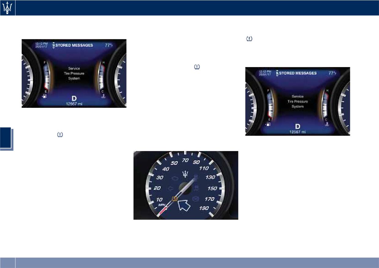
Driving
displays dashes (--) in place of the
assemblies. After replacing all four
minutes above 15 mph (24 km/h). The
pressure value.
wheel and tire assemblies (road tires)
TPMS will chime, the TPMS light
with tires not equipped with Tire
will flash for 75 seconds and then
Pressure Monitoring System sensors,
turn off. The instrument cluster will
drive the vehicle for 20 minutes above
then display the “Service Tire Pressure
15 mph (24 km/h). The TPMS will
System” message.
chime, the TPMS light
will flash on
and off for 75 seconds and then
remain on and the instrument cluster
will display the “Service Tire Pressure
System” message and then display
dashes (--) in place of the pressure
values. Beginning with the next
• Once you repair, replace or reinstall a
ignition switch cycle, the TPMS will no
tire with the compact spare tire, the
longer chime or display the “Service
TPMS will update automatically. The
Tire Pressure System” message in the
TPMS light
will turn OFF and the
instrument cluster but dashes (--) will
5
graphic in the instrument cluster will
The instrument cluster will also display
remain in place of the pressure values.
display a new pressure value instead
pressure values in place of the dashes
of dashes (--), as long as no tire
(--). On the next ignition switch cycle
pressure is below the low-pressure
the “Service Tire Pressure System”
warning limit in any of the four tires.
message will no longer be displayed as
The vehicle may need to be driven
long as no system fault exists.
for up to 20 minutes above 15 mph
General Information
(24 km/h) in order for the TPMS to
acquire and process the updated
This device complies with Part 15 of
information.
the FCC rules and RSS 210 of Industry
Canada. Operation is subject to the
TPMS Deactivation
following conditions:
The TPMS can be deactivated if
To reactivate the TPMS, replace all four
• This device may not cause harmful
replacing all four tire rims with wheel
wheel and tire assemblies (road tires)
interference.
and tire assemblies not using of TPMS
with tires equipped with TPMS sensors.
• This device must accept any
sensors, such as winter wheel and tire
Then, drive the vehicle for up to 20
interference received, including
284
Driving
interference that may cause
Fuel Requirements
undesired operation.
The TPMS sensors are regulated by the
The engines are designed to meet all
CAUTION!
MRXC4W4MA4 license.
environmental regulations and
• Maserati strongly recommends the
provide excellent fuel economy and
use of Premium unleaded fuel ONLY.
performance when using unleaded
Use of lesser grade fuel (other than
premium gasoline with an AKI octane
WARNING!
Premium) will lead to reduced
rating of 91 or above. AKI (Anti Knock
California Proposition 65
engine performance, and poor fuel
Index) is an average on the Research
Operating, servicing and maintaining
economy and can lead to the
Octane Number, RON, and the Motor
a passenger vehicle or off-road vehicle
Malfunction Indicator Light
Octane Number, MON (RON + MON/2
can expose you to chemicals including
illuminating on the instrument
gives you the AKI).
such as, engine exhaust, carbon
cluster. Continued use of lesser grade
For vehicle top performance, use
monoxide, phthalates and lead, that
fuel (other than Premium fuel) can
unleaded premium gasoline with no
which are know to the State of
lead to engine misfire problems and
less than 93 minimum AKI octane
California to cause cancer and birth
possible catalytic converter damage.
rating.
defects or other reproductive harm. To
• The anti-pollution devices of the
Poor quality gasoline can cause
minimize exposure, avoid breathing
vehicle require unleaded fuel to be
5
problems such as hard starting,
exhaust, do not idle the engine except
used at all times. Under no
stalling, and hesitations. If you
as necessary, service your vehicle in a
circumstance, not even in an
experience these symptoms, try
well-ventilated area and wear gloves
emergency, should leaded fuel be
another brand of gasoline before
or wash your hands frequently when
supplied to the fuel tank, not even a
considering service for the vehicle at
servicing your vehicle. For more
minimum quantity. This would
an Authorized Maserati Dealer.
information go to:
irreparably damage the catalytic
Besides using unleaded gasoline with
converters. An inefficient catalytic
the proper octane rating, gasoline
vehicle
converter results in noxious exhaust
that contain detergents, anti-corrosion
emissions which damage the
and stability additives are
environment.
recommended. Using gasoline that
have these additives may help improve
Reformulated Gasoline
fuel economy, reduce emissions, and
maintain vehicle performance.
Many areas of the country require the
use of cleaner burning gasoline,
referred to as “Reformulated
285
Driving
Gasoline”. Reformulated gasoline
Problems that result from using
Materials Added to Fuel
contains oxygenates and are
gasoline containing Methanol or
All gasoline sold in the United States is
specifically blended to reduce vehicle
gasoline containing more than 10%
required to contain effective
emissions and improve air quality.
Ethanol are not the responsibility of
detergent additives. Use of additional
Maserati supports the use of
Maserati and may not be covered
detergents or other additives is not
reformulated gasoline. Properly
under warranty.
needed under normal conditions and
blended reformulated gasoline will
MMT in Gasoline
they would result in additional cost.
provide excellent performance and
Therefore, you should not have to add
durability of engine and fuel system
MMT (Methylcyclopentadienyl
anything to the fuel.
components.
Manganese Tricarbonyl) is a
manganese containing metallic
Fuel System Warnings
Gasoline/Oxygenate Blends
additive that is blended into some
Some fuel suppliers blend unleaded
gasoline to increase octane.
gasoline with oxygenates such as
Gasoline blended with MMT provides
WARNING!
Ethanol. Fuels blended with
no performance advantage beyond
Follow these guidelines to maintain
oxygenates may be used in your
gasoline of the same octane number
your vehicle's performance:
vehicle.
without MMT.
5
Maserati recommends gasoline
• The use of leaded gasoline is
without MMT to be used in your
prohibited by Federal and Provincial
CAUTION!
law. Using leaded gasoline can impair
vehicle. The MMT content of gasoline
DO NOT use gasoline containing
may not be indicated on the gasoline
engine performance and damage the
Methanol or gasoline containing more
pump; therefore, you should ask the
emissions control system.
than 10% Ethanol. Use of these blends
gasoline station operator whether or
• The use of fuel additives, which are
may result in starting and driveability
not the gasoline contains MMT.
now being sold as octane enhancers,
problems, damage critical fuel system
It is even more important to look for
is not recommended. Most of these
components, cause emissions to exceed
gasoline without MMT in Canada,
products contain high concentrations
the applicable standard, and/or cause
because MMT can be used at levels
of methanol. Fuel system damage or
the Malfunction Indicator Light
to
higher than those allowed in the
vehicle performance problems
illuminate (see “Instrument Cluster” in
United States. MMT is prohibited in
resulting from the use of such fuels
section “Dashboard Instruments and
Federal and California reformulated
or additives is not the responsibility
Controls”. Pump labels should clearly
gasoline.
of Maserati.
communicate if a fuel contains greater
than 10% Ethanol.
286
Driving
NOTE:
abnormal conditions repaired
Refueling
promptly. Until repaired, drive with
Intentional tampering with the
emissions control system can result in
all side windows fully open.
Fuel Filler Neck Access
civil penalties civil penalties and could
To access the fuel filler neck, the filler
void the vehicle warranty.
door must be unlocked. From outside
WARNING!
the vehicle, this can only be done by
Carbon Monoxide Warnings
pressing the unlock
or the lock
California Proposition 65
button on the key fob RKE
Operating, servicing and maintaining
transmitter, in the same way as if
a passenger vehicle or off-road vehicle
WARNING!
can expose you to chemicals including
opening or closing the doors. If any of
the door lock controls is pressed from
Carbon monoxide (CO) in exhaust
such as, engine exhaust, carbon
inside the vehicle, the filler door will
gases is deadly. Follow the
monoxide, phthalates and lead, that
still remain open to allow refueling.
precautions below to prevent carbon
which are know to the State of
monoxide poisoning:
California to cause cancer and birth
• Press the indicated area on the filler
defects or other reproductive harm. To
door, which is located on the rear
• Do not inhale exhaust gases. They
minimize exposure, avoid breathing
left side of the vehicle: the filler
contain carbon monoxide, a
5
exhaust, do not idle the engine except
door will open completely.
colorless and odorless gas, which
as necessary, service your vehicle in a
can kill. Never run the engine in a
well-ventilated area and wear gloves
closed area, such as a garage, and
or wash your hands frequently when
never sit in a parked vehicle with
servicing your vehicle. For more
the engine running for an extended
information go to:
period. If the vehicle is stopped in
an open area with the engine
vehicle
running for more than a short
period, adjust the ventilation system
to force fresh, outside air into the
vehicle.
• Guard against carbon monoxide
with proper maintenance. Have the
exhaust system inspected every time
the vehicle is raised. Have any
287
Driving
fuel filler door, when opened.
• Close the fuel filler door.
• Never have any smoking materials lit
in or near the vehicle when the fuel
CAUTION!
filler door is open or the tank is
To avoid fuel spillage and overfilling,
being filled.
do not “top off” the fuel tank after
• Never add fuel when the engine is
filling.
running. This violates most
fire-prevention regulations and may
Emergency Refueling Funnel
cause the Malfunction Indicator
A funnel is provided (in the trunk in
Light
to turn on (see “Instrument
the tool box container) for emergency
Refill the Tank
Cluster” in section “Dashboard
refueling with a gas can.
Instruments and Controls”).
The fuel filler is sealed by an internal
closing tab, which is opened by the
• Fill the vehicle with fuel. Fuel tank
fuel nozzle of the service station when
capacity is indicated in the
refueling.
“Refillings” table in section
Only a nozzle of the suitable size can
5
“Features and Specifications”.
open the closing tab.
When the fuel nozzle “clicks” or
• Insert the fuel nozzle fully into the
shuts off, the fuel tank is basically
filler.
full: it is possible to further ensure
refueling by enabling the fuel nozzle
NOTE:
additional fuel supply until two
Only with a correct size nozzle you can
clicks. After the two additional clicks,
refuel.
the amount of fuel allowed by the
system is very low, we recommend
therefore not to persist further.
WARNING!
• Wait approximately 10 seconds
before removing the fuel nozzle in
• To avoid the risk of fire, do not
order to ensure completed supply of
approach the filler with open flames
residual fuel and restrict the risk of
or cigarettes!
fouling the fuel filler door area.
• To avoid the risk of inhaling noxious
• Remove the fuel nozzle.
fumes, do not breathe close to the
288
Driving
• Pull the release cable moderately to
Driving Conditions
avoid its possible break. It's not
WARNING!
possible to feel or hear the
Before the Trip
A fire may result if fuel is pumped
unlocking of the fuel filler door
into a portable container that is inside
Check the following at regular
actuator.
of a vehicle. You could be burned.
intervals and always before long trips:
Always place gas containers outside
• tire pressure and condition;
the vehicle while filling.
• levels of fluids and lubricants;
• conditions of the windshield wiper
Emergency Fuel Filler Door
blades;
Release
• clean the glass on the external light
If you are unable to unlock the fuel
and all other glass surfaces;
filler door using the key fob RKE
• proper operation of the indicator
transmitter, use the fuel filler door
lights and of the external lights.
emergency release located in the
trunk.
• Then open normally the fuel filler
CAUTION!
5
• Open the trunk lid (see “Trunk Lid
door.
It is however advisable to perform
Operation” in section “Before
these checks at least every 600 mi
Starting”).
(1000 km) and always following the
• Lift the access cover on the left side
maintenance schedule reported in
of the trunk.
section “Maintenance and Care”.
Before you drive:
• adjust seat position, steering wheel,
adjustable pedals (if equipped with)
and rearview mirrors in order to
have the best driving position;
• ensure that nothing (mat covers,
etc.) is obstructing the pedals
movement;
289
Driving
• carefully arrange and secure any
• Drive carefully. Night conditions
Some advices for driving in the rain are
objects in the trunk, to prevent them
demand more focus and attention.
listed below.
from moving forward in case of
• Reduce your speed, especially on
• Reduce your speed and keep a
sudden stops;
roads with no streetlights.
greater safety distance from the
• avoid heavy meals before a trip. A
• Stop at early signs of drowsiness.
vehicles in front of you. High speed
light snack helps keep your reflexes
Continuing to drive would be a risk
may result in a loss of vehicle control.
sharp. In particular, avoid drinking
for yourself and for others. Have a
• When driving on wet or slushy roads,
alcohol.
rest before continuing your trip.
it is possible for a wedge of water to
• Keep the vehicle at a greater
build up between the tire and road
distance from vehicles in front of you
surface. This is known as
WARNING!
than you would during the day: it is
aquaplaning and may cause partial
Passengers must only travel seated in
difficult to assess the speed of other
or complete loss of vehicle control
the vehicle seats, with the seat belts
vehicles when you only see the lights.
and stopping ability. To reduce this
fastened. Always check that the driver
• Use the high beams only outside of
possibility: slow down if the road has
and all passengers have the seat belts
densely-populated areas and when
standing water or puddles.
correctly fastened.
you are sure that they will not
• Heavy rain substantially reduces
5
disturb other drivers.
visibility. In these circumstances, even
Safe Driving
• When another vehicle is
during the day, turn on the low
approaching, switch from high
beams, to be more visible to other
Although the vehicle is equipped with
beams (if on) to low beams.
drivers.
active and passive safety devices, the
driver's conduct is always a decisive
• Keep lights and headlights clean.
• Set the air conditioning and heating
system controls on the defogging
factor for road safety.
• Outside of densely-populated areas,
function, in order to avoid any
Some simple rules for traveling safely
beware of animals crossing the road.
visibility problem.
in different conditions are listed
Driving in the Rain
below. Some of them will probably
• Periodically check the conditions of
already sound familiar but, in any case,
Rain and wet roads are dangerous. On
the windshield wiper blades.
it would be useful to read them
a wet road all maneuvers are more
• In low grip conditions use “I.C.E.”
carefully.
difficult since wheel grip on the road is
driving mode (see chapters “Drive
significantly reduced. This means that
Mode” in this section).
Driving at Night
braking distances increase considerably
The main guidelines to follow when
and road grip decreases.
driving at night are set out below.
290
Driving
Driving in Fog
Driving on Snow or Ice
If the fog is dense, avoid traveling if
Please consider some general advice
CAUTION!
possible.
for driving in these conditions, listed
Be aware that rear fog lights can
When driving in mist, blanket fog or
below.
bother the drivers following your
when there is the possibility of banks
vehicle: when visibility is back to
• Maintain a very moderate speed.
of fog, please consider some advices
normal, turn off these lights.
• Fit snow chains or specific tires if the
listed below.
road is covered with snow: see the
• Keep a moderate speed.
Driving in the Mountains
paragraphs “Tires - General
• Even in daytime, turn on the low
Mountain roads usually have many
Information” in this section.
beams and rear fog lights. Do not
narrow turns and curves, tunnels and
• We recommend you to activate the
use the high beams.
steep uphill or downhill slopes: please
“I.C.E.” mode (see chapters “Drive
• Remember that fog creates
consider some advices listed below.
Mode” in this section).
dampness on the asphalt and thus
• During the winter season, even
• Drive at a moderate speed, avoid
any type of maneuver is more
apparently dry roads can have icy
“cutting” corners.
difficult and braking distances are
sections. Be careful when crossing
• When driving inside a tunnel in
extended.
bridges, viaducts and roads that
5
daylight turn on the low beams in
• Keep a safe distance from the
have little exposure to the sun and
advance; avoid high beams and be
vehicle in front of you.
are bordered by trees and rocks.
aware of the rapid brightness
• Avoid sudden changes in speed as
They may be icy.
change. Avoid abrupt maneuvers
much as possible.
that could be dangerous for the
• Keep an ample safe distance from
• Whenever possible, avoid
following vehicle.
the vehicles in front of you.
overtaking.
• Never coast downhill with the
• If you are forced to stop the vehicle
engine off or in neutral.
(breakdowns, impossibility of
WARNING!
• Remember that passing other
proceeding due to poor visibility,
vehicles when driving uphill is slower
• Rapid acceleration on slippery
etc.), first of all, try to stop off of the
and thus requires more free distance
surfaces is dangerous. Unequal
travel lane. Then turn on the hazard
on the road. If you are being
traction can cause sudden pulling of
warning flashers and, if possible, the
overtaken on a hill, slow down and
the driving wheels. You could lose
low beams.
allow the other vehicle to pass.
control of the vehicle and possibly
(Continued)
291
Driving
(Continued)
before driving through the standing
• Driving through standing water
have a collision. Accelerate slowly
water.
limits your vehicle braking
and carefully whenever there is
capabilities, which increases
• Do not exceed 5 mph (8 km/h) when
likely to be poor traction (ice, snow,
stopping distances. Therefore, after
driving through standing water. This
wet mud, loose sand, etc.).
driving through standing water,
will minimize wave effects.
• Do not drive on or across a road or
drive slowly and lightly press on the
• Driving through standing water may
path where water is flowing and/or
brake pedal several times to
cause damage to your vehicle
rising (as in storm run-off). Flowing
progressively dry the brakes discs
drivetrain components. After driving
water can wear away the road or
and pads.
through standing water, do not drive if
path surface and cause your vehicle
you are not sure about drivetrain
• Getting water inside your vehicle
to sink into deeper water.
condition. Such damage is not covered
engine can cause it to lock up and
Furthermore, flowing and/or rising
by the New Vehicle Warranty.
stall out.
water can carry your vehicle away
• Getting water inside your vehicle
• Failure to follow these warnings
swiftly. Failure to follow this
engine can cause it to lock up and
may result in injuries that are serious
warning may result in injuries that
stall out, and cause serious internal
or fatal to you, your passengers, and
are serious or fatal to you, your
damage to the engine. Such damage
others around you.
passengers, and others around you.
5
is not covered by the New Vehicle
Although your vehicle is capable of
Warranty.
driving through shallow standing
• After driving through standing water
water, consider the following Cautions
always have the fluids (engine oil,
and Warnings before doing so.
transmission oil, etc) checked for
contamination at an Authorized
Maserati Dealer.
CAUTION!
• Always check the depth of the
standing water before driving
WARNING!
through it. Never drive through
standing water that is deeper than
• Driving through standing water
47 in (150 mm).
limits your vehicle traction
capabilities. Do not exceed 5 mph
• Determine the condition of the road
(8 km/h) when driving through
or the path that is under water and if
standing water.
there are any obstacles in the way
292
6 - In an Emergency
Tool Kit
294
Hazard Warning Flashers
295
In the Event of an Accident
295
In case of a Punctured Tire
296
Emergency Release of the Parking Brake
301
Transmission Manual Release of P (Park) Position
301
Auxiliary Jump-Start Procedure
302
Towing a Disabled Vehicle
304
293
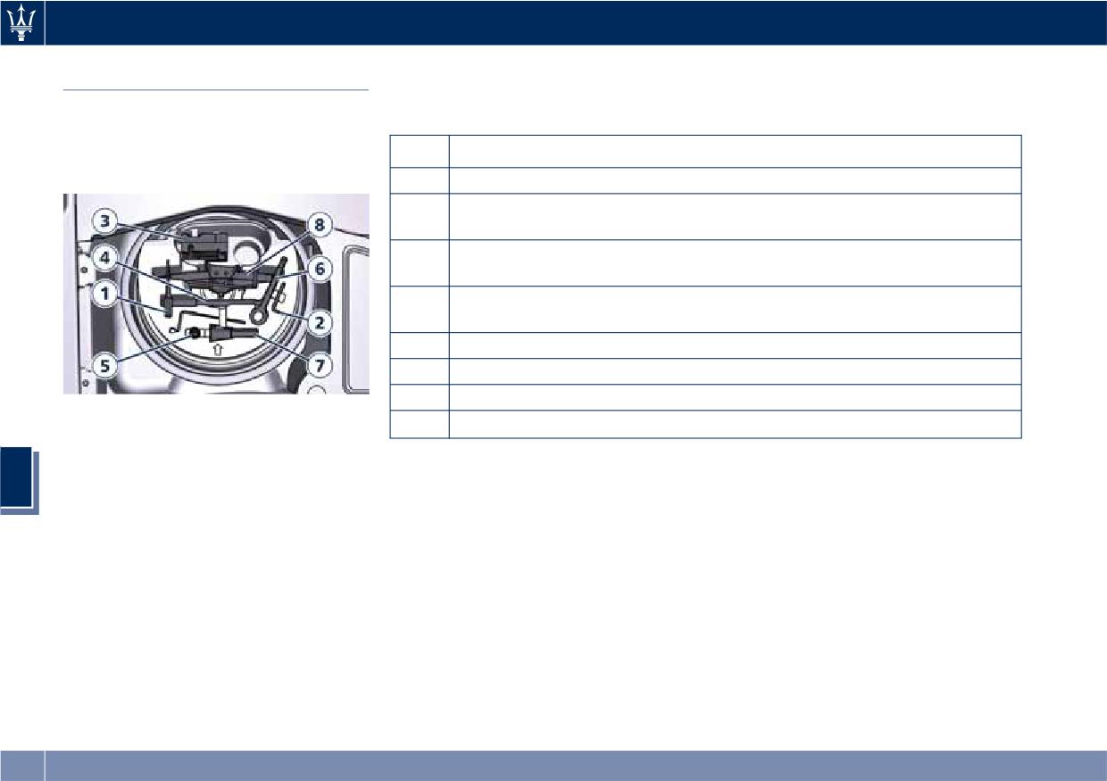
In an Emergency
The tools inserted in the container
Tool Kit
above the compact spare wheel are
The tools are located in the trunk
the following:
inside a preformed container and are
available by lifting the ground
Ref.
Description
coverage.
1
Double torx + cross-head screwdriver
2
8 mm Allen wrench for unscrewing the fastening nut of the reverse
light cluster
3
Electric compressor complete with pressure gauge for inflating the
compact spare wheel
4
Extended spanner with rubber coated handle for unscrewing/
tightening the wheel nuts
5
Adapter for wheel extended spanner
6
Tow hook
7
Funnel for emergency supply
8
Jack
6
294
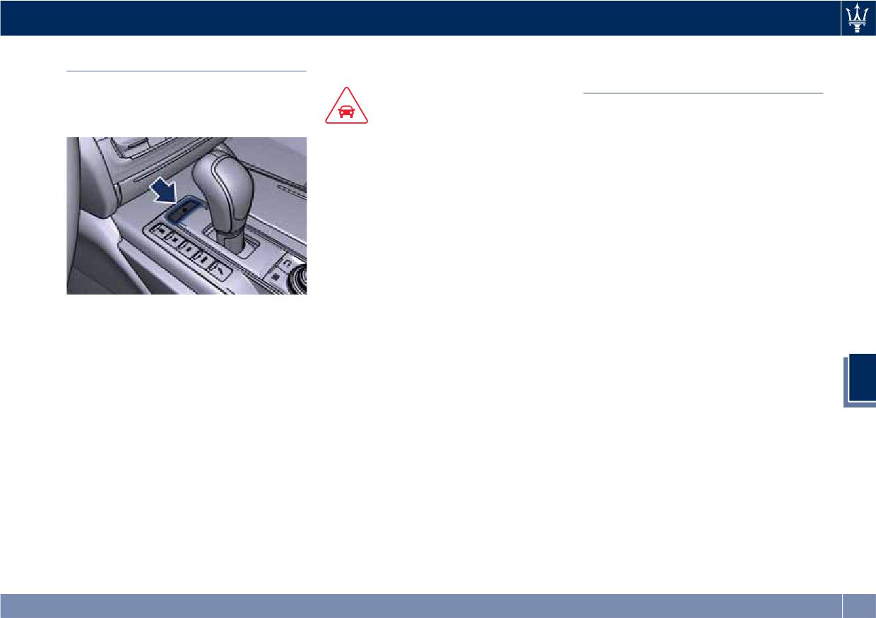
In an Emergency
though the ignition is placed in the
Hazard Warning Flashers
In the Event of an
OFF position.
Accident
The hazard warning flashers switch is
located in the central console in front
It is important always to keep calm.
of the transmission lever.
CAUTION!
• If not directly involved, stop at a safe
• When the hazard warning flashers
distance of at least ten yards
are activated, the turn signals
(meters) away from the accident
control is disabled.
area.
• With extended use the hazard
• If on a highway, stop without
warning flashers may wear down
obstructing the emergency lane and
your battery.
be especially careful if you need to
exit the vehicle.
• Turn off the engine and switch on
the hazard warning flashers.
• At night, illuminate the accident
Press the switch to turn on the hazard
area with the headlights.
warning flashers to warn oncoming
• Always act with caution to avoid the
traffic of an emergency. When these
risk of being crashed into by other
lights illuminate, the turn signals, the
drivers.
related warning lights on the
6
instrument cluster and the button
• Indicate that an accident has
start flashing.
occurred by placing the emergency
Press the switch a second time to turn
triangle (if equipped) in a well
off the hazard warning flashers.
visible position and at the prescribed
This is an emergency warning system
distance.
and it should not be used when the
• Call the emergency services,
vehicle is in motion. Use it when your
providing as much information as
vehicle is disabled and it is creating a
possible. On the highway, use the
safety hazard for other motorists.
special call boxes.
When you must leave the vehicle to
• Remove the ignition key (if present)
seek assistance, the hazard warning
from the vehicles involved.
flashers will continue to operate even
295
In an Emergency
• If fuel or other chemical products can
which are know to the State of
In case of a Punctured Tire
be smelled, do not smoke and ask
California to cause cancer and birth
people around you to put their
defects or other reproductive harm. To
If the vehicle is equipped with a
cigarettes out.
minimize exposure, avoid breathing
compact spare wheel.
• To extinguish fires, even small ones,
exhaust, do not idle the engine except
Using the Compact Spare
use a fire extinguisher, blankets, sand
as necessary, service your vehicle in a
Wheel
or earth. Never use water.
well-ventilated area and wear gloves
or wash your hands frequently when
NOTE:
• In multiple accidents occurred on
servicing your vehicle. For more
highways, particularly where visibility
The compact spare wheel is supplied in
information go to:
is poor, there is a high risk of being
aluminium or steel: the pictures show
involved in other collisions. Leave the
the one in aluminium.
vehicle
vehicle immediately and move away
from the area.
The compact spare wheel is stored in
the trunk and is supplied deflated in
In case of Injured Persons
order to limit the amount of space
• Never leave the injured person alone.
occupied. An electric compressor is also
Persons not directly involved in the
provided for inflating. In the event of
accident are also required to give
a tire puncture, proceed as follows.
assistance.
• Stop the vehicle in a place that does
• Do not crowd around injured
not constitute a danger to traffic and
6
persons.
where the wheel can be changed
• Reassure the injured person that help
safely. The vehicle must be level and
is on the way.
on firm ground.
• Select the P (Park) mode and then
engage manually the electric parking
WARNING!
brake and move the ignition switch
California Proposition 65
to OFF position.
Operating, servicing and maintaining
• If necessary, turn the hazard warning
a passenger vehicle or off-road vehicle
flashers on and place the warning
can expose you to chemicals including
triangle (if equipped) at the required
such as, engine exhaust, carbon
distance.
monoxide, phthalates and lead, that
296
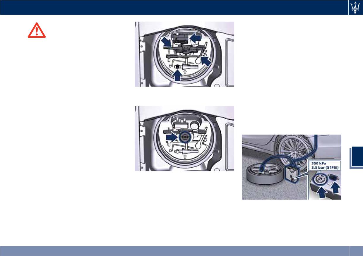
In an Emergency
• Insert the power plug into one of
the available power outlets fitted in
WARNING!
the trunk or passenger
• The jack should be used on level
compartment.
firm ground wherever possible.
• Set the ignition device on ACC or
• It is recommended that the wheels
RUN position.
of the vehicle be chocked, and that
• Turn the compressor on by pressing
no person should remain in a vehicle
the switch.
that is being jacked.
• Stop the compressor by pressing the
• If the vehicle has been stopped on a
switch again, when the pressure
slope or an uneven surface, place
• Unscrew and pull out the locking
indicated by the gauge reaches the
chocks or other suitable items in
wheel knob.
recommended level (see “Tire
front of or behind the wheels to
Inflation Pressure” in section
stop the vehicle from moving.
“Features and Specifications”) and
• Never start or run the engine with
screw the cap on the compact spare
the vehicle on a jack.
wheel valve.
• No person should place any portion
of their body under a vehicle that is
supported by a jack.
6
• Lift the ground coverage of the
trunk.
• Take the tools for changing the
• Take the container and the compact
wheel (indicated in picture) from the
spare wheel out of the trunk.
container.
• Remove from the compressor case
the inflation hose and the cable with
a plug for the power outlet.
• Unscrew the valve cap of the
compact spare wheel and screw the
fitting of the inflation hose onto the
valve.
297
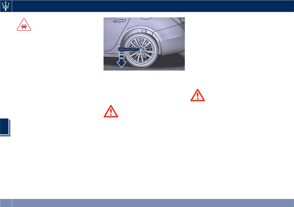
In an Emergency
specific fitting wrench provided with
the “Wheel Security Stud Bolt Kit”,
CAUTION!
available in the “Genuine
• In order to obtain a more accurate
Accessories” range.
reading, the compressor should be
• Fit the compact spare wheel with the
switched off when checking the tire
valve stem facing outward, securing
pressure of the compact spare wheel
it with the five bolts previously
on the pressure gauge.
removed.
• Do not run the compressor for more
• Turn the lever of the jack to lower
than 20 minutes: there is a risk it
the vehicle and remove the jack.
could overheat. Also, prolonged
• Place the jack near the wheel to be
• Fully tighten the bolts, alternately
power absorption may discharge the
changed as illustrated.
tightening diametrically opposite.
battery, subsequently preventing the
• Make sure that the head of the jack
engine from starting.
is correctly inserted in one of the
• The compressor has been designed
slots beneath the rocker panel.
WARNING!
exclusively to inflate compact spare
• FOR ALUMINIUM SPARE WHEEL
wheels; do not use it to inflate air
Observe the tightening torque for
mattresses, floatation devices, etc.
WARNING!
the bolts securing the spare wheel
• Never position yourself under a
(72 ± 7 lbf·ft/ 98 ± 10 Nm).
• Remove the center cover of the
6
jacked vehicle.
• FOR STEEL SPARE WHEEL
wheel rim (if equipped) levering into
• Never use the jack to carry out
Observe the tightening torque for
the provided groove on the outer
maintenance or repairs under the
the bolts securing the spare wheel
ledge of the cover.
vehicle.
(63 ± 7 lbf·ft/ 86 ± 10 Nm).
• Fit the adapter on the wrench.
Extend the wrench as shown, then
• To avoid the risk of forcing the
• Turn the jack lever until the wheel is
vehicle off the jack, do not tighten
loosen by approximately one turn,
raised a few centimeters off the
the wheel bolts fully until the
the five bolts on the wheel to be
ground.
vehicle has been lowered. Failure to
changed.
• Completely unscrew the five bolts
follow this warning may result in
and remove the wheel. In case a
personal injury.
wheel security stud bolt is installed, it
can only be removed by using the
298
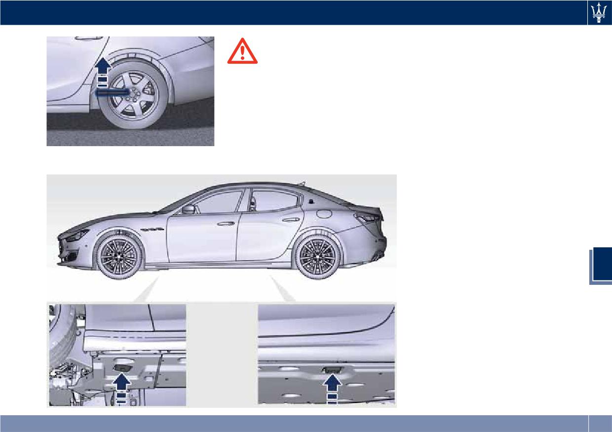
In an Emergency
compact spare wheel; when this
limit is exceeded, the stability, road
WARNING!
holding and braking of the vehicle
• The spare wheel is narrower than
will be compromised. Avoid
standard wheels and must only be
accelerating to full speed, heavy
used to travel the distance required
braking and fast cornering.
to reach a service station, where the
• The compact spare wheel must be
punctured tire can be repaired or
inflated to the recommended tire
replaced.
pressure (see “Tire Inflation
• Do not exceed a maximum speed of
Pressure” in section “Features and
50 mph (80 km/h) when using the
Specifications”).
• For safety reasons, it is absolutely
forbidden to drive with more than
one compact spare wheel fitted on
the vehicle.
• Snow chains cannot be fitted on the
compact spare wheel.
• The spare wheel can travel a
maximum of 1,800 mi (3.000 km).
6
To Refit the Standard Wheel with
Repaired or Replaced Tire
• Following the procedure and the
caution described above, raise the
vehicle and remove the compact
spare wheel reusing the supplied
wrench with adapter, suitably
extended.
• Fit the standard wheel with repaired
or replaced tire.
299
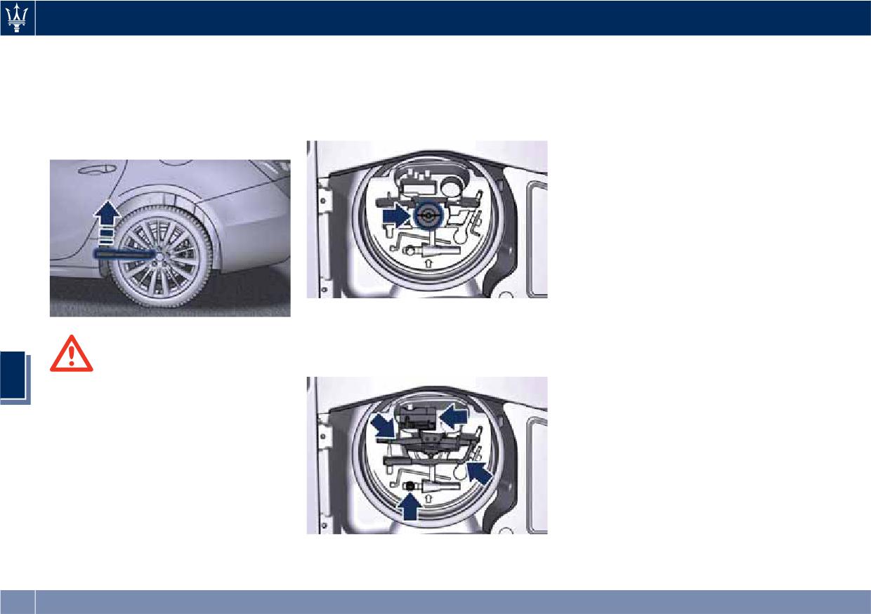
In an Emergency
• Tighten the original bolts on the
• fix everything in place with the
• lower the ground coverage at the
wheel.
locking knob;
bottom of the trunk.
• Lower the vehicle and remove the
• wrap the power cable and the
jack.
inflation hose inside the compressor
• Fully tighten the bolts, alternately
case;
tightening diametrically opposite.
• place the compressor, the jack, the
wrench and the adapter in the
container inside the compact spare
wheel;
WARNING!
6
Observe the tightening torque for the
bolts securing the wheels (72 ± 7 lbf·ft
/ 98 ± 10 Nm).
• Reassemble the center cover (if
equipped) on the wheel rim.
Once finished:
• completely deflate the compact
spare wheel by pressing on the valve
with the overhang of the valve cap;
• place the compact spare wheel and
• reposition the other tools;
tool container in the trunk;
300
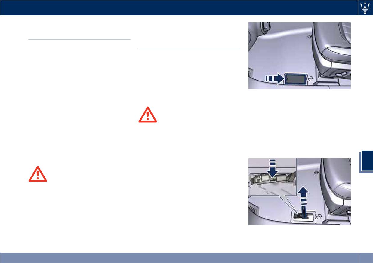
In an Emergency
Emergency Release of the
Transmission Manual
Parking Brake
Release of P (Park)
Position
In the event the electric parking brake
locks due to a system failure (see
The manual disengagement of the
“Parking Brake” in section “Driving”),
shift from P (Park) has the purpose to
it is not possible to move the vehicle,
allow towing the vehicle if not
since the actuator that operates on
normally possible using the shift lever
the brake pad inside each rear caliper
(such as inability to start the engine).
will lock the rear wheels.
This procedure is exclusively intended
After verifying that the battery is
• With the tip of a screwdriver press
for emergency situations, only!
sufficiently charged (otherwise use an
the clip shown in the picture box
external power source connected to
and lift the strap up to release the
the vehicle electric system to operate
transmission from the P (Park)
WARNING!
the EPB control lever and try to unlock
position. The new position will allow
Always secure your vehicle by fully
the parking brake), for moving the
vehicle moving and towing.
applying the parking brake, before
vehicle it is necessary to force the
• Release the parking brake only when
activating the manual park release.
actuator to release the rear brake
the vehicle is securely connected to a
Activating the manual park release
discs. Contact the Authorized Maserati
tow vehicle.
could allow your vehicle to roll away
Dealer to carry out this operation.
if it is not secured by the parking
6
brake. Activating the manual park
release on an unsecured vehicle could
WARNING!
lead to serious injury or death for
If the parking brake has been
those in or around the vehicle.
activated in manual or automatic
mode and it is not possible to release
The cover that allows the emergency
it by operating on the lever of the
manual park release is located on the
central console, do not move the
left part of the driver’s foot well.
vehicle since rear brake calipers might
• Lift the mat on the driver side to
be damaged. For more information on
access the cover.
vehicle towing see "Towing a Disabled
• Slip the cover from its seat.
Vehicle" chapter in this section.
301
In an Emergency
if it is not secured by the parking
Auxiliary Jump-Start
brake. Activating the manual park
Procedure
CAUTION!
release on an unsecured vehicle could
If your vehicle has a discharged battery
• To jump start a vehicle do not use a
lead to serious injury or death for
it can be jump-started using a set of
portable battery, a booster pack or
those in or around the vehicle.
jumper cables and a battery of another
any other booster source with a
vehicle or by using a portable battery
system voltage greater than 14 Volts
NOTE:
booster. It is necessary to have proper
or damage to the battery, starter
If you need to disconnect the battery
jumper cables in order to connect the
motor, alternator or electrical system
from the vehicle electrical system, see
booster battery to the remote posts of
of the vehicle with the discharged
“Maintenance - Free Battery” in
the discharged battery. Booster cables
battery may occur.
section “Maintenance and Care”).
have positive and negative terminal
• Do not use a battery charger for
clamps and are identified by the
emergency starting under any
sheath color (red = positive, black =
circumstances. You could damage the
negative).
electronic systems, particularly the
WARNING!
control units managing the ignition
California Proposition 65
NOTE:
and fuel supply functions.
Operating, servicing and maintaining
An Authorized Maserati Dealer can
a passenger vehicle or off-road vehicle
• If the battery is completely
provide you with information about
can expose you to chemicals including
discharged when the windows are
the “Maserati Jumper Cables Kit”,
such as, engine exhaust, carbon
fully raised, open the door with the
6
available in the “Genuine Accessories”
monoxide, phthalates and lead, that
utmost care; do not close the door
range.
which are know to the State of
again until it is possible to lower the
California to cause cancer and birth
Jump-starting can be dangerous if
window.
defects or other reproductive harm. To
done improperly so please follow the
minimize exposure, avoid breathing
procedures in this section carefully.
exhaust, do not idle the engine except
NOTE:
WARNING!
as necessary, service your vehicle in a
When using a portable battery booster
Always secure your vehicle by fully
well-ventilated area and wear gloves
pack, follow the battery
applying the parking brake, before
or wash your hands frequently when
manufacturer’s operating instructions
activating the manual park release.
servicing your vehicle. For more
and precautions.
Activating the manual park release
information go to:
could allow your vehicle to roll away
302