Galeo HD785-7 DUMP TRUCK. Operation and Maintenance Manual (2006) - page 9
 

  Index      Manuals     Galeo HD785-7 DUMP TRUCK. Operation and Maintenance Manual (2006)


Search            copyright infringement  


Content      ..     7      8      9      10     ..


Galeo HD785-7 DUMP TRUCK. Operation and Maintenance Manual (2006) - page 9


MAINTENANCE

SERVICE PROCEDURE

LUBRICATION

 1. Stop the engine.
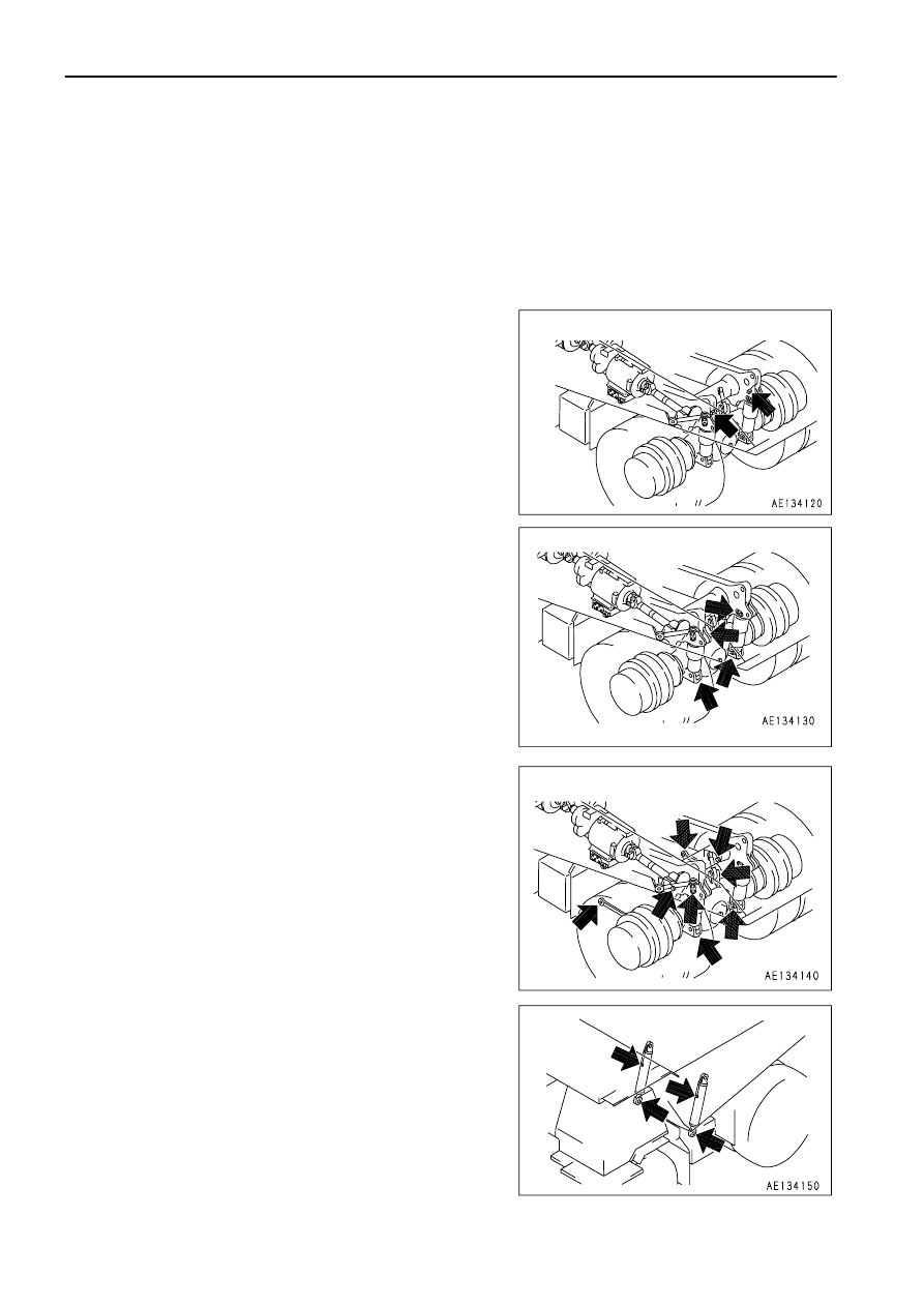
 2. Use the grease pump to pump in grease through the grease fitting marked by the arrow.
 3. After greasing, wipe off any old grease that was pushed out.

Carry out the greasing operation every day when operating in places where the grease flows out easily, such as
when traveling through mud or water.

(1) Dump body hinge pin (left and right: 1 place each)

(2) Rear suspension (left and right: 2 places each)

(3) Rear axle support (left and right: 4 places each)

(4) Hoist cylinder pin (left and right: 2 places each)

Lower the dump body before greasing.

4 - 54

MAINTENANCE

SERVICE PROCEDURE

MAINTENANCE

SERVICE PROCEDURE

(5) Front suspension (left and right: 1 place each)

(6) Steering linkage (left and right: 3 places each)

(7) Exhaust brake control link (1 place) (if equipped)

CHECK DRIVE SHAFT

If there is any problem, such as looseness of the drive shaft
connection, play in the spline or bearing portion, or runout of the
shaft, please contact your Komatsu distributor for repair.

4 - 55

MAINTENANCE

SERVICE PROCEDURE

CHECK LEVEL OF BATTERY ELECTROLYTE

Perform this check before operating the machine.

 WARNING

Do not use the battery if the battery electrolyte level is below the LOWER LEVEL line. This will accelerate deterioration of the
inside of the battery and reduce the service life of the battery. In addition, it may cause an explosion.
The battery generates flammable gas and there is danger of explosion, do not bring fire or sparks near the battery.
Battery electrolyte is dangerous. If it gets in your eyes or on your skin, wash it off with a large amount of water and consult a
doctor.
When adding distilled water to the battery, do not allow the battery electrolyte to go above the UPPER LEVEL line.  If the
electrolyte level is too high, it may leak and cause damage to the paint surface or corrode other parts.

NOTICE
When adding distilled water in cold weather, add it before starting operations in the morning to prevent the electrolyte from
freezing.

Inspect the battery electrolyte level at least once a month and follow the basic safety procedures given below.  

WHEN CHECKING ELECTROLYTE LEVEL FROM SIDE OF BATTERY

If it is possible to check the electrolyte level from the side of the battery, check as follows.

 1. Use a wet cloth to clean the area around the electrolyte level

lines and check that the electrolyte level is between the
UPPER LEVEL (U.L.) and LOWER LEVEL (L.L.) lines.
If the battery is wiped with a dry cloth, static electricity may
cause a fire or explosion.

 2. If the electrolyte level is below the midway point between the

U.L. and L.L. lines, remove cap (1) and add distilled water to
the U.L. line.

 3. After adding distilled water, tighten cap (1) securely.

REMARK

If distilled water is added to above the U.L. line, use a syringe to
lower the level to the U.L. line.  Neutralize the removed fluid with
baking soda (sodium bicarbonate), then flush it away with a large
amount of water or consult your Komatsu distributor or battery
maker.

4 - 56

MAINTENANCE

SERVICE PROCEDURE

WHEN IT IS IMPOSSIBLE TO CHECK ELECTROLYTE LEVEL FROM SIDE OF BATTERY

If it is impossible to check the electrolyte level from the side of the battery, or there is no display of the UPPER
LEVEL line on the side of the battery, check as follows.

 1. Remove cap (1) at the top of the battery, look through the water

filler port, and check the electrolyte surface.  If the electrolyte
does not reach the sleeve, add distilled water so that the level
reaches the bottom of the sleeve (UPPER LEVEL line) without
fail.

Use the diagram below for reference, and check if the electrolyte reaches the bottom of the sleeve.

 2. After adding distilled water, tighten cap (1) securely.

REMARK

If distilled water is added to above the bottom of the sleeve, use a syringe to lower the level to the bottom of the
sleeve. Neutralize the removed fluid with baking soda (sodium bicarbonate), then flush it away with a large amount
of water or consult your Komatsu distributor or battery maker.

WHEN IT IS POSSIBLE TO USE INDICATOR TO CHECK ELECTROLYTE LEVEL

(If equipped)
If it is possible to use and indicator to check the electrolyte level, follow the instructions given.

4 - 57

MAINTENANCE

SERVICE PROCEDURE

CHECK ALTERNATOR BELT TENSION, ADJUST

CHECKING

The belt should normally deflect by above 15 mm (0.6 in) (a) when
pressed with the thumb (with a force of approx. 58.8 N (6 kgf) at a
point midway between the drive pulley and alternator pulley.

ADJUSTING

 1. Loosen 2 bolts (1) for installing the cover, then remove the

cover.

 2. Loosen bolts and nuts (2) - (5), then turn nut (6) to adjust the

belt tension.
Tighten nut (6) to increase the belt tension; loosen nut (6) to
loosen the belt tension.

 3. After adjusting the belt tension, tighten bolts and nuts (2) - (5)

in numerical order to hold the alternator in position.

 4. Tighten nut (6).
 5. Reinstall the cover removed in step 1. Confirm that no part of

the cover touches any moving part of the alternator.

REMARK

Check each pulley for breakage and wear of the V-groove. In particular, check that the V-belt does not touch the
bottom of the V-groove.
If any problem is found, ask your Komatsu distributor for replacement of the pulley.
If the V-belt is so lengthened that it cannot be adjusted any more or if it has any cuts or cracks, replace it.
If the V-belt has been replaced with a new part, there will be initial elongation, so inspect and adjust it again after
one-hour of operation.

4 - 58

MAINTENANCE

SERVICE PROCEDURE

CHECK AIR CONDITIONER COMPRESSOR BELT TENSION, ADJUST

CHECKING

The belt should normally deflect by 10 mm (0.4 in) (a) when
pressed with the thumb (with a force of approx. 58.8 N (6 kgf)) at
a point midway between the air compressor pulley and drive pulley.

ADJUSTING

 1. Loosen 2 bolts (1) for installing the cover, then remove the

cover.

 2. Loosen bolt (2).
 3. Turn nut (3) to adjust so that the belt deflects by approx. 10mm

(0.4 in) when pressed with a finger force of approx. 58.8 N (6
kgf) at a point midway between the air conditioner compressor
pulley and drive pulley.

 4. Tighten bolt (2) and nut (3) to secure the compressor in

position.

 5. Check each pulley for damage, wear of the V-groove, and wear

of the V-belt. In particular, be sure to check that the V-belt is not
touching the bottom of the V-groove.

 6. If the V-belt is so lengthened that it cannot be adjusted any

more or if it has any cuts or cracks, replace it.

 7. Install the cover removed in Step 1.
 8. If any part has been replaced with a new part, there will be

initial elongation, so adjust again after operating the machine
for 1 hour.

4 - 59

MAINTENANCE

SERVICE PROCEDURE

CLEAN BREATHERS

Remove the mud and dirt from around the breathers, then remove the breathers and wash out the dirt with clean
diesel oil or flushing oil.

Transmission, brake cooling oil tank (2 places)

Steering, hoist oil tank

 1. Remove nut (1), then remove cover (2) and wash element (3).
 2. Install element (3), then install cover (2) and nut (1).

4 - 60

MAINTENANCE

SERVICE PROCEDURE

CHECK FRAME

 DANGER

Always carry out the operation to remove or insert the body pivot pin with at least two workers. This operation is carried out
with the dump body raised, so if the dump body goes down during the operation, it will lead to serious injury or even death.
When carrying out inspection with the dump body raised, always set the dump control lever to the HOLD position, set the dump
control lever lock knob to the LOCK position, then insert the body pivot pin. If the body pivot pin is not inserted, the dump body
may go down when the dump control lever is operated, and catch or cause serious injury or even death to the person carrying
out the inspection.

 1. Wash the frame to make it easier to check.
 2. Check all parts of the frame for damage.

In particular, check the colored portions in the diagram and if
any cracks or damage are found, repair the damage. Please
contact your Komatsu distributor for details of the repair
procedure.

CHECK BRAKING CAPACITY OF FOOT BRAKE

 WARNING

When checking the braking capacity of the foot brake, there is danger that the machine may suddenly move and be damaged or
cause serious personal injury. Always do the following.

Select a wide, flat area with sufficient distance to make it possible to stop the machine if it suddenly moves.
If the machine suddenly moves when the braking capacity of the foot brake is being checked, reduce the engine speed
immediately, move the gear shift lever to the N position, and set the parking brake to the PARKING position to stop the machine.

NOTICE
If inspection is carried out when the body pilot lamp is lighted up and the shift indicator shows "F1", there is danger that the
internal parts of the transmission may be damaged.
Before carrying out inspection, lower the dump body securely and check that the body pilot lamp has gone out, then place the gear
shift lever at the "D" position and check that the shift indicator shows "F2".

Check the braking capacity of the foot brake as follows.

 1. Stop the machine on flat ground and depress service brake (1).
 2. Set shift lever (2) to the D position, gradually raise the engine

speed, and check that the machine does not move even when
the engine speed reaches 1570 rpm.

 3. Lower the engine speed, set shift lever at N position, and then

set parking brake valve lever at PARKING position. If any
problem is found, ask your Komatsu distributor for repair.

4 - 61

MAINTENANCE

SERVICE PROCEDURE

CHECK BRAKING CAPACITY OF RETARDER BRAKE

 WARNING

When checking the braking capacity of the retarder brake, there is danger that the machine may suddenly move and be damaged
or cause serious personal injury. Always do the following.

Select a wide, flat area with sufficient distance to make it possible to stop the machine if it suddenly moves.
If the machine suddenly moves when the braking capacity of the retarder brake is being checked, reduce the engine speed
immediately, move the gear shift lever to the N position, and depress the foot brake to stop the machine.

NOTICE
If inspection is carried out when the body pilot lamp is lighted up and the shift indicator shows "F1", there is danger that the
internal parts of the transmission may be damaged.
Before carrying out inspection, lower the dump body securely and check that the body pilot lamp has gone out, then place the gear
shift lever at the "D" position and check that the shift indicator shows "F2".

Check the braking capacity of the retarder brake as follows.

 1. Stop the machine on flat ground and pull retarder control lever

(1) fully.

 2. Set shift lever (2) to the D position, gradually raise the engine

speed.  If the machine does not move even when the engine
speed reaches 1200 rpm, it is normal.

 3. Lower the engine speed, set gear shift lever at N position. If

any problem is found, ask your Komatsu distributor for repair.

4 - 62

MAINTENANCE

SERVICE PROCEDURE

CHECK BRAKING CAPACITY OF PARKING BRAKE

 WARNING

When checking the braking capacity of the parking brake, there is danger that the machine may suddenly move and be damaged
or cause serious personal injury. Always do the following.

Select a wide, flat area with sufficient distance to make it possible to stop the machine if it suddenly moves.
If the machine suddenly moves when the braking capacity of the parking brake is being checked, reduce the engine speed
immediately, move the gear shift lever to the N position, and depress the foot brake to stop the machine.

NOTICE
If inspection is carried out when the body pilot lamp is lighted up and the shift indicator shows "F1", there is danger that the
internal parts of the transmission may be damaged.
Before carrying out inspection, lower the dump body securely and check that the body pilot lamp has gone out, then place the gear
shift lever at the "D" position and check that the shift indicator shows "F2".

Check the braking capacity of the parking brake as follows.

 1. Stop the machine on flat ground and set parking brake switch

(1) to PARKING.

 2. Set shift lever (2) to the D position, gradually raise the engine

speed. If the machine does not move even when the engine
speed reaches 1335 rpm, it is normal.

 3. Lower the engine speed, set gear shift lever at N position. If

any problem is found, ask your Komatsu distributor for repair.

4 - 63

MAINTENANCE

SERVICE PROCEDURE

CHECK, CLEAN AUTOMATIC SUSPENSION

 WARNING

Follow the precautions below strictly.

One should sit on the operator's seat, preparing to stop the engine at
any moment, and contact with the other.
Set the parking brake switch at PARKING position to prevent the
machine from moving.
When working near fan or belts, do not bring your body or any materials
closer that can be dragged into.
Do not touch the gearshift lever.  When you operate the dump lever,
always give a signal to your fellow workers to tell them to move to a safe
area.
If the materials or tools are dropped onto fan or belts, they fly away or
cut.  Never drop or insert materials or tools.

 1. When bolts of inspection cover (1) are loosened and the cover

is moved to the side, the inspection hole can be seen.

 2. Check the position of the link.

Check that it moves to the following positions:
For mormal travel when empty: soft (A)
When the brake is depressed: medium (B)
When the dump lever is at any position other than FLOAT: hard
(C)

If any problem is found, please contact your Komatsu distributor for inspection and adjustment.

If operations are carried out on muddy or wet ground, mud will stick to the link, and the movement may become slow,
so check and clean.

4 - 64

MAINTENANCE

SERVICE PROCEDURE

CHECK OF ACCUMULATOR GAS PRESSURE

For handling of the accumulator, see "HANDLING SUSPENSION CYLINDER, ACCUMULATOR (PAGE 2-29)".

REMARK

If the engine stops during travel, the brake can be operated with the oil pressure in the accumulator temporarily.

CHECK OF FUNCTION

 1. Stop the machine on a flat place and set the parking brake switch to the PARKING position.
 2. Start the engine and run it at medium speed for 1 minute, and then stop it.
 3. Turn the starting switch to the ON position and depress the brake pedal several times.  After the brake pedal is

depressed some times, the brake oil pressure caution lamp lights up.

If the brake oil pressure caution lamp lights up when the brake pedal is depressed 4 times or less, the gas
pressure in the accumulator may be low. Ask your Komatsu distributor for inspection.
If the brake oil pressure caution lamp does not light up when the brake pedal is depressed 5 times, the gas
pressure in the accumulator is normal.

REMARK

Check the function within 5 minutes after stopping the engine. If the engine is kept stopped, the gas pressure in the
accumulator lowers and cannot be checked.

4 - 65

MAINTENANCE

SERVICE PROCEDURE

EVERY 500 HOURS SERVICE

Maintenance for every 250 hours service should be carried out at the same time.

CHANGE OIL IN ENGINE OIL PAN, REPLACE ENGINE OIL FILTER CARTRIDGE

 WARNING

The parts and oil is at high temperature after the engine has been operated, and it can result in a burn. Wait for the oil to cool down
before changing it.

Refill capacity: 129 liters (34.08 US gal)
Prepare a filter wrench

 1. Remove drain plug (1), then install the standard drain hose.
 2. Set a container in position to catch the oil, then loosen drain the

valve (2) slowly to avoid getting oil on yourself, and drain the
oil.  Be careful not to loosen drain valve (2) too much.  This will
deform the stopper pin inside the valve.

 3. Check the drained oil, and if there are excessive metal

particles or foreign material, please contact your Komatsu
distributor.

 4. Remove the drain hose, then tighten drain valve (2) and drain

plug (1).
Tightening torque
Drain plug (1), drain valve (2): 68.6

±

 9.8N

·

m

(7

±

 1 kgf

·

m, 50.6

±

 7.2 lbft)

 5. Using the filter wrench, turn filter cartridge (3) to the left and

remove it. When doing this, do not carry out the operation from
immediately below and be careful not to get oil over yourself. In
particular, immediately after the engine is stopped, a large
amount of oil may come out, so wait for about 10 minutes
before starting the operation.

 6. Clean the filter holder, fill the new filter cartridge with oil, then

coat the seal and thread of the filter cartridge with oil (or coat
thinly with grease) and install.

 7. When installing the filter cartridge, tighten until the packing face is in contact with the filter holder, then tighten

a further 3/4 - 1 turn.

 8. Pour in the specified amount of engine oil from oil filler (F).
 9. Run the engine for a short time at idle, then check the oil if it is

filled up to a specified level. For details, see "CHECK OIL
LEVEL IN ENGINE OIL PAN, ADD OIL (PAGE 3-78)".

4 - 66

MAINTENANCE

SERVICE PROCEDURE

REPLACE FUEL PREFILTER CARTRIDGE

 WARNING

After the engine has been operated, all parts are at high temperature, so do not replace the filter immediately.  Wait for all parts
to cool down before starting the operation.
High pressure is generated inside the engine fuel piping system when the engine is running.
When replacing the filter, wait for at least 30 seconds after stopping the engine to let the internal pressure go down before
replacing the filter.
Do not bring any fire or flame close.

NOTICE

Genuine Komatsu fuel filter cartridges use a special filter that has highly efficient filtering ability.  When replacing the filter
cartridge, always use a genuine Komatsu part.  
The common rail fuel injection system used on this machine consists of more precise parts than the conventional injection
pump and nozzle.  
If any part other than a genuine Komatsu filter cartridge is used, dust or dirt may get in and cause problems with the injection
system.  Always avoid using substitute parts.
When carrying out inspection or maintenance of the fuel system, pay more attention than normal to the entry of dirt.  If dirt is
stuck to any part, use fuel to wash it off completely.

There is one fuel pre-filter cartridge each on the left and right sides, so follow the same procedure to replace both
the left and right cartridges.

Container to catch the oil
Prepare a filter wrench

 1. Close fuel valve (1) at the side face of the fuel tank.
 2. Set an oil receiving container under the fuel prefilter cartridge.

 3. Turn cup (3) of water separator installed at the bottom of the

filter cartridge (2) to the left and remove it. (This cup is used
again.)

 4. Using a filter wrench, turn filter cartridge (2) counterclockwise

to remove it.

 5. Install cup (3) to the bottom of the new fuel pre-filter cartridge.

(When doing this, always replace the O-ring.)

Tightening torque of cup: 10 N

·

m {1.0 kgm, 7.2 lbft}

 6. Clean the filter holder.

4 - 67

MAINTENANCE

SERVICE PROCEDURE

MAINTENANCE

SERVICE PROCEDURE

NOTICE
When filling the filter cartridge with fuel, carry out the filling operation with
cap (A) fitted.
Cap (A) acts to prevent the entry of dirt or dust into the filter cartridge.

 7. Fill the filter cartridge with clean fuel through the 8 small holes

(B) in the new filter cartridge.

 8. Coat the packing surface of the filter cartridge with oil.

 9. Remove filter cartridge cap (A) and install to the filter holder.

10. When installing, tighten until the packing surface contacts the seal surface of the filter holder, then tighten it 3/4

of a turn.
If the filter cartridge is tightened too far, the packing will be damaged and this will lead to leakage of fuel. If the
filter cartridge is too loose, fuel will also leak from the packing, so always tighten the correct amount.

When tightening with a filter wrench, be extremely careful not to dent or damage the filter.

11. Check that the drain plug at the bottom of the water separator cup is tightened securely.

Tightening torque: 0.2 to 0.45 N

·

m (0.02 to 0.046 kgf

·

m, 0.1 to 0.3 lbft)

12. Open the fuel cock(1).

4 - 68

MAINTENANCE

SERVICE PROCEDURE

REPLACE TRANSMISSION OIL FILTER ELEMENT

 WARNING

The parts and oil are at high temperature after the engine is stopped, and may cause burns. Wait for the temperature to go down
before starting the work.
When removing the oil filler cap, turn it slowly to release the internal pressure, then remove it.

 1. Set the container to catch the oil under the filter case.
 2. Remove drain plug (1) at the bottom of the filter case, drain the

oil, then tighten the plug again.

 3. Loosen hexagonal portion (3) of case (2), then remove case

(2).

 4. Remove the element and clean the inside of the case.
 5. Replace the filter gasket and O-ring with new parts. Coat the

gasket and O-ring thinly with clean engine oil before installing.

 6. Assemble the new element, then set the case in position and

install it.

Tightening torque for drain: 49 to 58.8 N

·

m

(5 to 6 kgf

·

m, 36.2 to 43.4 lbft)

Tightening torque for case: 58.8 to 78.5 N

·

m

(6 to 8 kgf

·

m, 43.4 to 57.9 lbft)

 7. Run the engine for a short time at idle, then stop the engine, and check that the oil is up to the specified level.

For details, see "CHECK OIL LEVEL IN TRANSMISSION CASE, ADD OIL (PAGE 3-79)".

Run the engine at high idle, and when the oil is warmed up, if the Maintenance caution lamp flashes, replace the
element immediately.

4 - 69

MAINTENANCE

SERVICE PROCEDURE

EVERY 1000 HOURS SERVICE

Carry out maintenance for EVERY 250 HOURS and EVERY 500 HOURS SERVICE at the same time.

REPLACE CORROSION RESISTOR CARTRIDGE

 WARNING

All the engine parts are at high temperature after the engine has been operated, so never replace the cartridge immediately after
finishing operations.
Wait for the oil to cool down before replacing the cartridge.

Prepare a filter wrench

 1. Set valve (1) at the top of the corrosion resistor to the CLOSED

position, to close it.

 2. Set the container to catch the water under the cartridge.
 3. Using a filter wrench, remove cartridge (2).
 4. Clean the filter holder, coat the steel surface of the new filter

cartridge with clean engine oil, then install it.

 5. When installing, tighten until the gasket contacts the seal

surface of the filter holder, then tighten a further 2/3 turns.
If the filter cartridge is tightened too far, the gasket will be
damaged and this will lead to leakage of water. If the filter is too
loose, water will also leak from the gap at the gasket, so always
tighten the correct amount.

 6. Set valve (1) to the OPEN position to open it.
 7. After replacing the cartridge, start the engine and check that

there is no leakage of water from the filter seal surface. If there
is any leakage of water, check the tightening of the filter
cartridge.

4 - 70

MAINTENANCE

SERVICE PROCEDURE

REPLACE FUEL MAIN FILTER CARTRIDGE

 WARNING

After the engine has been operated, all parts are at high temperature, so do not replace the filter immediately.  Wait for all parts
to cool down before starting the operation.
High pressure is generated inside the engine fuel piping system when the engine is running.
When replacing the filter, wait for at least 30 seconds after stopping the engine to let the internal pressure go down before
replacing the filter.
Do not bring any fire or flame close.

NOTICE

Genuine Komatsu fuel filter cartridges use a special filter that has highly efficient filtering ability.  When replacing the filter
cartridge, always use a genuine Komatsu part.  
The common rail fuel injection system used on this machine consists of more precise parts than the conventional injection
pump and nozzle.  
If any part other than a genuine Komatsu filter cartridge is used, dust or dirt may get in and cause problems with the injection
system.  Always avoid using substitute parts.
When carrying out inspection or maintenance of the fuel system, pay more attention than normal to the entry of dirt.  If dirt is
stuck to any part, use fuel to wash it off completely.

STANDARD SPECIFICATION

There is one fuel main filter cartridge each on the left and right sides, so follow the same procedure to replace both
the left and right cartridges.
Bleed the air from the fuel line in the same way on both the left and right sides.

Container to catch the oil
Prepare a filter wrench

 1. Close fuel valve (1) at the side face of the fuel tank.
 2. Set the container to catch the fuel under the filter cartridge.

 3. Using a filter wrench, turn filter cartridge (2) counterclockwise

to remove it.

NOTICE

Do not fill the fuel filter cartridge with fuel.
Remove the cap in the center and install the fuel filter.

 4. Clean the filter holder, coat the packing surface of the new filter

cartridge thinly with oil, then install the filter cartridge to the filter
holder.

4 - 71

MAINTENANCE

SERVICE PROCEDURE

 5. When installing, tighten until the packing surface contacts the seal surface of the filter holder, then tighten a

further 3/4 of a turn.
If the filter cartridge is tightened too far, the packing will be damaged and this will lead to leakage of fuel. If the
filter cartridge is too loose, fuel will also leak from the packing, so always tighten to the correct amount.

 6. After replacing filter cartridge (2), loosen air bleed plug (3), and open fuel valve (1).
 7. Fill the fuel tank with fuel.
 8. Loosen wing nut (5) holding lever (6) of priming pump (4) in

position. Pump lever (6) and make fuel overflow until no more
bubbles come out with the fuel from air bleed plug (3).

 9. Tighten air bleed plug (3).

Tightening torque for air bleed plug
7.8 to 9.8 N

·

m{0.8 to 1 kg

·

m, 5.8 to 7.2 lbft}

10. Loosen air breather (7) at the side of the supply pump.
11. Pump lever (6) and make fuel overflow until no more bubbles

come out with the fuel from air breather (7).

12. Tighten air breather (7), then tighten wing nut (5) of priming

pump (4) securely to lock lever (6) in position.

Tightening torque for air breather:
4.9 to 6.9 N

·

m {0.5 to 0.7 kg

·

m, 3.6 to 5.1 lbft}

Tightening torque for wing screw
6.9 to 12.7N

·

m{0.7 to 1.3kg

·

m}

13. After replacing the filter cartridge, start the engine, and check

for any leakage of fuel from the filter seal surface. If there is any
leakage of oil, check the tightening condition of the filter
cartridge. If there is still leakage of oil, repeat Steps 1 - 3 to
remove the filter cartridge. If there is any damage or foreign
material embedded in the packing surface, replace the
cartridge with a new part and repeat Steps 4 - 10 to install.

4 - 72

MAINTENANCE

SERVICE PROCEDURE

EXTRA LOW-GRADE FUEL SPECIFICATION MACHINE

With the extra low-grade fuel specification machine, two fuel filters are additionally installed to the engine block (one
each on left and right).
(This gives a total of two each on the left and right.)

Container to catch the oil
Prepare a filter wrench

 1. Close fuel valve (1) at the side face of the fuel tank.
 2. Set the container to catch the fuel under the filter cartridge.

 3. Using a filter wrench, turn filter cartridge (2) counterclockwise

to remove it.

NOTICE

Do not fill the fuel filter cartridge with fuel.
Remove the cap in the center and install the fuel filter.

 4. Clean the filter holder, coat the packing surface of the new filter

cartridge thinly with oil, then install the filter cartridge to the filter
holder.

 5. When installing, tighten until the packing surface contacts the

seal surface of the filter holder, then tighten a further 3/4 of a
turn.
If the filter cartridge is tightened too far, the packing will be
damaged and this will lead to leakage of fuel. If the filter
cartridge is too loose, fuel will also leak from the packing, so
always tighten to the correct amount.

 6. Open the fuel cock(1).
 7. After completing the replacement of fuel filter cartridge (2),

bleed the air from the circuit. For details, see "BLEED AIR
FROM FUEL CIRCUIT (PAGE 4-43)".

 8. After replacing the filter cartridge, start the engine, and check

for any leakage of fuel from the filter seal surface. If there is any
leakage of oil, check the tightening condition of the filter
cartridge. If there is still leakage of oil, repeat Steps 1 - 3 to
remove the filter cartridge. If there is any damage or foreign
material embedded in the packing surface, replace the
cartridge with a new part and repeat Steps 4 - 8 to install.

4 - 73

MAINTENANCE

SERVICE PROCEDURE

CHANGE OIL IN TRANSMISSION, BRAKE COOLING OIL TANK, WASH STRAINER

 WARNING

The parts and oil are at high temperature immediately after the engine is stopped, and may cause burns. Wait for the
temperature to go down before starting the work.
When removing the oil filler cap, turn it slowly to release the internal pressure, then remove it.

Refill capacity: 210 liters (55.48 US gal)

Change the oil every 1000 hours or every 10,000 km, whichever comes sooner.

 1. Stop the engine.
 2. Set a container to catch the oil directly under the drain plug of

the transmission case.

 3. Remove drain plug (1).
 4. Loosen drain valve (2) and drain the oil, then tighten the plug

again.

 5. Install drain plug (1).

 6. Remove bolts (3), then remove the cover and take out strainer

(4).

 7. Remove any dirt stuck to the strainer, then wash in clean diesel

fuel or flushing oil. If the strainer is damaged, replace it.

 8. Install strainer (4).
 9. Install the cover with bolts (3).

Inside rear brake cooling chamber

10. Remove plug (5). If this plug is removed, it is easier to drain the

oil from the brake chamber.

4 - 74

MAINTENANCE

SERVICE PROCEDURE

MAINTENANCE

SERVICE PROCEDURE

11. Remove cooling drain plug (6) and drain the oil from the brake

chamber.

NOTICE
Drain the oil from the brake chamber on both the left and right sides.

12. After completely draining the oil from the brake chamber, install

plug (5) and cooling drain plug (6).

Inside front brake cooling chamber

13. Stop the machine so that plug (7) is at the bottom.
14. Remove plug (7) and drain the oil from the brake chamber.

15. Remove plug (8). If this plug is removed, it is easier to drain the

oil from the brake chamber.

16. Remove cooling drain plug (9) and drain the oil from the brake

chamber.

NOTICE
Drain the oil from the brake chamber on both the left and right sides.

17. After completely draining the oil from the brake chamber, install

plug (7), (8) and cooling drain plug (9).

18. Pour in the specified amount of engine oil from oil filler (F).
19. After adding oil, check that the oil is at the specified level. See

"CHECK OIL LEVEL IN TRANSMISSION CASE, ADD OIL
(PAGE 3-79)".

4 - 75

MAINTENANCE

SERVICE PROCEDURE

CHANGE OIL IN BRAKE SUB-TANK

 WARNING

The parts and oil are at high temperature immediately after the engine is stopped, and may cause burns. Wait for the
temperature to go down before starting the work.
When removing the oil filler cap, turn it slowly to release the internal pressure, then remove it.

Refill capacity: 36 liters (9.51 US gal)

 1. Depress the brake pedal at least 20 times to reduce the pressure inside the brake control accumulator to 0.
 2. Set the container to catch the oil directly under drain plug (P).

Remove drain plug (P), drain the oil, then tighten the plug
again.

NOTICE
Do not start the engine before adding oil. If the engine is started and there
is no oil, the brake pump will be damaged.

 3. Before starting the engine, add oil to the H level through the oil

filler port in the transmission case.

 4. After this, add oil to the top of level gauge (H) (36 liters (9.51 US

gal)) through oil filler port (F) of the brake sub-tank.

 5. After starting the engine, run at low idling and add oil so that the

oil level is at the top of level gauge (H).

 6. Carry out the warming-up operation of the engine until the torque converter oil temperature gauge goes above

40

°

.

 7. When the torque converter oil temperature gauge rises to 40

°

, bleed the air from the brakes.

Front brake: See "BLEED AIR FROM FRONT BRAKE (PAGE 4-39)".
Rear brake: See "BLEED AIR FROM REAR BRAKE (PAGE 4-38)".
Front parking brake: See "BLEED AIR FROM FRONT PARKING BRAKE (PAGE 4-41)".
Rear parking brake: See "BLEED AIR FROM REAR PARKING BRAKE (PAGE 4-40)".

NOTICE
Do not reuse any oil that is discharged during the air bleed operation. It will cause damage to the equipment.

 8. After completing the air bleed operation, run the engine again at low idling and add oil so that the oil level is at

the top of level gauge (H).

4 - 76

MAINTENANCE

SERVICE PROCEDURE

REPLACE TRANSMISSION, BRAKE COOLING OIL FILTER ELEMENT

 WARNING

The parts and oil are at high temperature immediately after the engine is stopped, and may cause burns. Wait for the
temperature to go down before starting the work.
When removing the oil filler cap, turn it slowly to release the internal pressure, then remove it.

 1. Turn the cap of oil filler (F) slowly to release the internal

pressure, then remove the cap.

 2. Remove bolt (1), then remove cover (2).
 3. Take out the element, then wash the inside of the case and the

removed parts.

 4. Install the new element, then install cover (2) with bolt (1).

If the filter Maintenance caution lamp (if equipped) lights up when the engine water temperature gauge is in the white
range and the engine is running at 1200 to 2100 rpm, replace the element immediately.

4 - 77

MAINTENANCE

SERVICE PROCEDURE

REPLACE BRAKE OIL FILTER ELEMENT

 WARNING

The parts and oil are at high temperature immediately after the engine is stopped, and may cause burns. Wait for the
temperature to go down before starting the work.
When removing the oil filler cap, turn it slowly to release the internal pressure, then remove it.

Prepare a filter wrench

 1. Depress the brake pedal at least 20 times to reduce the pressure inside the brake control accumulator to 0.

REMARK

When the pressure in the accumulator is released, the operating effort of the brake pedal becomes lighter and the
oil pressure noise disappears.

 2. Remove filter case (1).

 3. Take out the element and wash the inside of the filter case.

Replace O-ring (2) and backup ring (3) on the filter case with
new parts, coat thinly with clean oil, then install.

 4. Assemble a new element in the filter case, coat the O-ring of

the element thinly with clean oil, then install.
Tightening torque: 78.4 to 98 N

·

m

{8 to 10 kgf

·

m, 57.9 to 72.3 lbft}

4 - 78

MAINTENANCE

SERVICE PROCEDURE

LUBRICATION

 1. Using a grease pump, pump in grease through grease fittings marked by arrows.
 2. After greasing, wipe off any old grease that was pushed out.

(1) Transmission mount (1 place)

(2) Automatic suspension link (left and right: 1 place each)

(3) Fan pulley (1 place)
(4) Tension pulley (2 places)

1. Remove the alternator belt cover.
2. Add grease through the grease fitting until grease oozes out

from the seal.

3. After greasing, install the cover removed in Step 1.

NOTICE
Do not use air pressure or oil pressure to carry out high-pressure greasing.

4 - 79

MAINTENANCE

SERVICE PROCEDURE

CHECK WEAR OF REAR BRAKE DISC

 WARNING

Carry out this check when the brake oil temperature is below 60

°

C (140

°

F).

If the disc wear approaches the wear limit, check the condition frequently, regardless of the maintenance interval. In addition,
check the retarder capacity carefully.
Always carry out this operation with the engine stopped.

 1. Stop the machine on level ground, set the parking brake switch to the PARKING position, then check that the

other brakes are not applied before starting inspection.

 2. Remove cap nut (1).

 3. Push in until rod (2) of the gauge contacts the piston.  Do not

depress the brake pedal when doing this.

 4. If slit (3) of rod (2) goes in beyond guide end face (4), it means

that the disc has reached the wear limit.
If this happens, please contact your Komatsu distributor for
inspection and maintenance.

 5. Install cap nut (1) removed in Step 2.

Tightening torque: 128 to 186 N

·

m

(13 to 19 kgf

·

m, 94 to 137.4 lbft)

REMARK

On a new machine, the position of the guide is adjusted so that slit (5) comes to guide end face (4), so do not
loosen locknut (6) except when replacing the disc.
When the engine is started and the rod is pushed in, the rod is pushed back by the brake cooling oil pressure,
so carry out this operation with the engine stopped.

4 - 80

MAINTENANCE

SERVICE PROCEDURE

CHECK WEAR OF FRONT BRAKE DISC

 WARNING

Carry out this check when the brake oil temperature is below 60

°

C (140

°

F).

If the disc wear approaches the wear limit, check the condition frequently, regardless of the maintenance interval. In addition,
check the retarder capacity carefully.
Always carry out this operation with the engine stopped.

 1. Stop the machine on level ground, set the parking brake switch to the PARKING position, then check that the

other brakes are not applied before starting inspection.

 2. Remove cap nut (1).

 3. Push in until rod (2) of the gauge contacts the piston.  Do not

depress the brake pedal when doing this.

 4. If slit (3) of rod (2) goes in beyond guide end face (4), it means

that the disc has reached the wear limit.
If this happens, please contact your Komatsu distributor for
inspection and maintenance.

 5. Install cap nut (1) removed in Step 2.

Tightening torque: 128 to 186 N

·

m

(13 to 19 kgf

·

m, 94 to 137.4 lbft)

REMARK

On a new machine, the position of the guide is adjusted so that slit (5) comes to guide end face (4), so do not
loosen locknut (6) except when replacing the disc.
When the engine is started and the rod is pushed in, the rod is pushed back by the brake cooling oil pressure,
so carry out this operation with the engine stopped.

4 - 81

MAINTENANCE

SERVICE PROCEDURE

RECOVER OIL LEAKING FROM FLOATING SEAL

 WARNING

The parts and oil are at high temperature immediately after the engine is stopped, and may cause serious burns.  Wait for the
temperature to go down before starting the operation.
If there is still pressure remaining inside the case, the oil or plug may fly out.
Loosen the plug slowly to release the pressure.

Use the same procedure to recover the oil from the front left and right and rear left and right sides.

 1. Place a container to catch the oil under drain plug (P).
 2. Remove drain plug (P), drain the oil, then tighten the plug again.

Front

Rear

4 - 82

MAINTENANCE

SERVICE PROCEDURE

CHECK OF ENGINE AIR INTAKE PIPING CLAMPS FOR LOOSENESS

Check the clamps between the air cleaner, turbocharger, aftercooler, and engine for looseness. If any clamp is
loosened, retighten it.

Tightening torque of clamp (1): 8.8

±

 0.5 N

·

m {0.9

±

 0.05 kgf

·

m, 6.5

±

 0.4 lbft}

Tightening torque of clamp (2): 10.5

±

 0.5 N

·

m {1.07

±

 0.05 kgf

·

m, 7.7

±

 0.4 lbft}

4 - 83

MAINTENANCE

SERVICE PROCEDURE

EVERY 2000 HOURS SERVICE

Carry out maintenance for EVERY 250 HOURS, EVERY 500 HOURS and EVERY 1000 HOURS SERVICE at the
same time.

REPLACE STEERING, HOIST OIL TANK FILTER ELEMENT

 WARNING

The parts and oil are at high temperature immediately after the engine is stopped, and may cause burns. Wait for the
temperature to go down before starting the work.
When removing the oil filler cap, turn it slowly to release the internal pressure, then remove it.

 1. Turn the cap of oil filler (F) slowly to release the internal

pressure, then remove the cap.

 2. Remove bolt (1), then remove cover (2).
 3. Take out the element, then wash the inside of the case and the

removed parts.

 4. Install the new element, then install cover (2) with bolt (1).

If the filter Maintenance caution lamp (if equipped) lights up when the engine water temperature gauge is in the white
range and the engine is running at 1200 to 2100 rpm, replace the element immediately.

CHANGE OIL IN FINAL DRIVE CASE

 WARNING

The parts and oil are at high temperature immediately after the engine is stopped, and may cause serious burns.  Wait for the
temperature to go down before starting the operation.
When removing plug, oil may spout out. So turn the plug gradually to release the internal pressure, then carefully remove it.

Refill capacity: Left, right 64 liters (16.91 US gal)

 1. Stop the machine so that the dipstick is horizontal below the

center line and drain plug (P) is immediately at the bottom.

 2. Remove drain plug (P), drain the oil, then tighten the plug

again.

 3. Add oil through the hole for plug (G) to the specified level.
 4. After adding oil, check that the oil is at the specified level. See

"CHECK OIL LEVEL IN FINAL DRIVE CASE, ADD OIL
(PAGE 4-53)".

4 - 84

MAINTENANCE

SERVICE PROCEDURE

CHANGE OIL IN DIFFERENTIAL CASE

 WARNING

The parts and oil are at high temperature immediately after the engine is stopped, and may cause serious burns.  Wait for the
temperature to go down before starting the operation.
When removing plug, oil may spout out. So turn the plug gradually to release the internal pressure, then carefully remove it.

Refill capacity: 137 liters (36.2 US gal)

 1. Remove drain plug (P), drain the oil, then tighten the plug

again.

 2. Add oil through the hole for plug (G) to the specified level.
 3. After adding oil, check that the oil is at the specified level. See

"CHECK OIL LEVEL IN DIFFERENTIAL CASE, ADD OIL
(PAGE 4-53)".

CLEAN DIFFERENTIAL CASE BREATHER

 WARNING

The parts and oil are at high temperature after the engine is stopped, and may cause serious burns.  Wait for the temperature
to go down before cleaning the engine breather.
When using compressed air, there is a hazard that dirt may be blown up and cause serious injury.
Always use safety glasses, dust mask, or other protective equipment.

 1. Remove all mud and dirt from around the breather before

removing the breather.  Use clean diesel fuel or flushing oil to
rinse the dirt out from the inside.

 2. Blow with compressed air and dry.
 3. After flushing, install the breather.

4 - 85


Content      ..     7      8      9      10     ..