Galeo HD785-7 DUMP TRUCK. Operation and Maintenance Manual (2006) - page 7
 

  Index      Manuals     Galeo HD785-7 DUMP TRUCK. Operation and Maintenance Manual (2006)


Search            copyright infringement  


Content      ..     5      6      7      8     ..


Galeo HD785-7 DUMP TRUCK. Operation and Maintenance Manual (2006) - page 7


OPERATION

TROUBLESHOOTING

IF BATTERY IS DISCHARGED

 WARNING

It is dangerous to charge a battery when mounted on a machine. Make sure that it is dismounted before charging.
When checking or handling the battery, stop the engine and turn the starting switch key to the OFF position.
The battery generates hydrogen gas, so there is a hazard of explosion. Do not bring lighted cigarettes near the battery, or do
anything that will cause sparks.
Battery electrolyte is dilute sulfuric acid, and it will attack your clothes and skin. If it gets on your clothes or on your skin,
immediately wash it off with a large amount of water. If it gets in your eyes, wash it out with fresh water and consult a doctor.
When handling batteries, always wear safety glasses and rubber gloves.
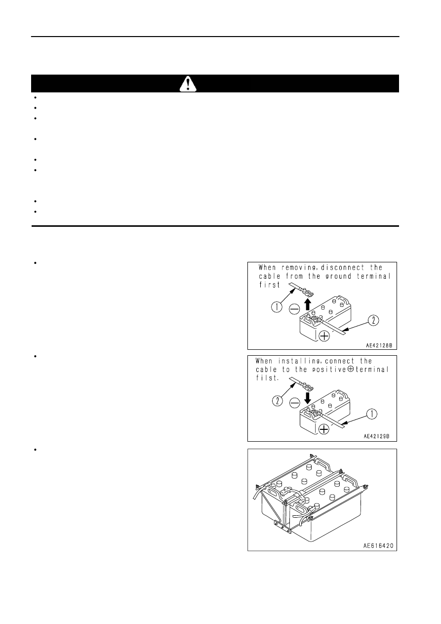
When removing the battery, first disconnect the cable from the ground (normally the negative (-) terminal).  When installing,
install the positive (+) terminal first.
If a tool touches the positive terminal and the chassis, there is danger that it will cause a spark, so be extremely careful.
If the terminals are loose, there is danger that the defective contact may generate sparks that will cause an explosion.
When removing or installing the terminals, check which is the positive (+) terminal and which is the negative (-) terminal.

REMOVAL AND INSTALLATION OF BATTERY

Before removing the battery, remove the ground cable (normally
connected to the negative (-) terminal).
If any tool touches between the positive terminal and the
chassis, there is a hazard of sparks being generated.

When installing the battery, connect the ground cable last.

When replacing the battery, hold the battery securely in position
with the battery mounting clamps.

Tightening torque of mounting nut: 9.8 to 14 N

·

m

(1 to 1.5 kgf

·

m, 7.2 to 10.8 lbft)

NOTICE
After securing the battery, check that it does not move.  If it moves, tighten
it again securely.

3 - 146

OPERATION

TROUBLESHOOTING

PRECAUTIONS FOR CHARGING BATTERY

CHARGING BATTERY WHEN MOUNTED ON MACHINE

When charging the battery, if the battery is not handled correctly,
there is danger that the battery may explode.  Always follow the
instructions in "IF BATTERY IS DISCHARGED (PAGE 3-146)"
and the instruction manual accompanying the charger, and do as
follows.

Set the voltage of the charger to match the voltage of the battery
to be charged. If the correct voltage is not selected, the charger
may overheat and cause an explosion.
Connect the positive (+) charger clip of the charger to the
positive (+) terminal of the battery, then connect the negative (-)
charger clip of the charger to the negative (-) terminal of the
battery. Be sure to attach the clips securely.
Set the charging current to 1/10 of the value of the rated battery capacity; when carrying out rapid charging, set
it to less than the rated battery capacity.
If the charger current is too high, the electrolyte will leak or dry up, and this may cause the battery to catch fire and
explode.
If the battery electrolyte is frozen, do not charge the battery or start the engine with a different power source.
There is a danger that this will ignite the battery electrolyte and cause the battery to explode.
Do not use or charge the battery if the battery electrolyte level is below the LOWER LEVEL line. This may cause
an explosion. Check the battery electrolyte level periodically and add distilled water to bring the electrolyte level
to the UPPER LEVEL line.

3 - 147

OPERATION

TROUBLESHOOTING

STARTING ENGINE WITH BOOSTER CABLE

When starting the engine with a booster cable, do as follows:

PRECAUTIONS WHEN CONNECTING AND DISCONNECTING BOOSTER CABLE

 WARNING

When connecting the cables, never contact the positive (+) and negative
(-) terminals.
When starting the engine with a booster cable, wear safety glasses and
rubber gloves.
Be careful not to let the normal machine and problem machine contact
each other. This prevents sparks from generating near the battery which
could ignite the hydrogen gas given off by the battery.
Make sure that there is no mistake in the booster cable connections.
The final connection is to the engine block of the problem machine, but
sparks will be generated when this is done, so connect to a place as far
as possible from the battery.
When disconnecting the booster cable, take care not to bring the clips
in contact with each other or with the machine body.

NOTICE

The size of the booster cable and clip should be suitable for the battery size.
The battery of the normal machine must be the same capacity as that of the problem machine.
Check the cables and clips for damage or corrosion.
Make sure that the cables and clips are firmly connected.

CONNECTING THE BOOSTER CABLES

Keep the starting switch of the normal machine and problem machine in the OFF position.
Connect the booster cable as follows, in the order of the numbers marked in the diagram.

 1. Connect one clip of booster cable (A) to the positive (+)

terminal of the problem machine.

 2. Connect the other clip of booster cable (A) to the positive (+)

terminal of the normal machine.

 3. Connect one clip of booster cable (B) to the negative (-)

terminal of the normal machine.

 4. Connect the other clip of booster cable (B) to the engine block

of the problem machine.

3 - 148

OPERATION

TROUBLESHOOTING

STARTING THE ENGINE

 CAUTION

Make sure that the parking brake switch is at PARKING position and the shift lever is at N (neutral) position for both normal
machine and the problem machine.

 1. Make sure the clips are firmly connected to the battery terminals.
 2. Start engine of the normal machine and run it at high idle speed.
 3. Turn the starting switch of the problem machine to the START position and start the engine.

If the engine doesn't start at first, try again after 2 minutes or so.

DISCONNECTING THE BOOSTER CABLES

After the engine has started, disconnect booster cables in the reverse order in which they were connected.

 1. Remove one clip of booster cable (B) from the engine block of

the problem machine.

 2. Remove the other clip of booster cable (B) from the negative (-)

terminal of the normal machine.

 3. Remove one clip of booster cable (A) from the positive (+)

terminal of the normal machine.

 4. Remove the other clip of booster cable (A) from the positive (+)

terminal of the problem machine.

3 - 149

OPERATION

TROUBLESHOOTING

OTHER TROUBLE

ELECTRICAL SYSTEM

(    ): Always contact your Komatsu distributor when dealing with these items.
In cases of problems or causes which are not listed below, contact your Komatsu distributor for repairs.

Problem

Main causes

Remedy

Lamp does not glow brightly even
when engine runs at high speed

Defective wiring

Insufficient battery charge
Defective adjustment of belt
tension

( Check, repair loose terminals,

 disconnections)

  Charge, Add distilled water
  Adjust alternator belt tension.

 See EVERY 250 HOURS
 SERVICE.

Lamp flickers while engine is
running

Battery charge system caution pilot
lamp lights up while engine is
running

Defective alternator
Defective wiring

( Replace)
( Check, repair)

Abnormal noise is generated from
alternator

Defective alternator

( Replace)

Starting motor does not turn when
starting switch is turned to ON

Defective wiring
Defective starting switch
Insufficient battery charge
Defective battery switch
Loose ground cable terminals
between engine and chassis

( Check, repair)
( Replace switch)
  Charge
( Replace switch)
( Check, repair)

Starting motor turns engine
sluggishly

Defective wiring
Insufficient battery charge

( Check, repair)
  Charge

Starting motor disengages before
engine starts

Defective wiring
Insufficient battery charge

( Check, repair)
  Charge

3 - 150

OPERATION

TROUBLESHOOTING

CHASSIS

(    ): Always contact your Komatsu distributor when dealing with these items.
In cases of problems or causes which are not listed below, contact your Komatsu distributor for repairs.

Problem

Main causes

Remedy

Torque converter oil temperature
caution lamp flashes

Leakage of oil or entry of air due
to damage or defective tightening
of oil pipe, pipe joint
Wear, scuffing of gear pump
Insufficient oil in transmission
case
Loose fan belt

Clogged oil cooler
Long distance traveled in torque
converter range
Disconnected, broken wiring to
sensor

( Check, repair)

( Check, repair)
  Add oil to specified level. See

 CHECK BEFORE STARTING.

  Replace belt. See EVERY 500

 HOURS SERVICE.

( Clean or replace)
  Drive in direct range

( Repair, connect wiring)

Steering wheel is heavy

Lack of grease at link
Internal leakage inside steering
cylinder

  Add grease
( Replace cylinder seal)

Steering wheel pulls

Tire inflation pressure not
uniform on left and right

Dragging, pulling of front brake

  Make tire inflation pressure

 uniform. See CHECK BEFORE
 STARTING.

  Check wear of front brake disc.

 For details, see EVERY 500
 HOURS SERVICE.

Braking effect is poor when brake
pedal is depressed

Disc has reached wear limit

Insufficient oil pressure
Insufficient brake oil

Air in brake circuit

( Replace disc)

  Charge to specified pressure
  Add oil to the brake sub

 tank. See CHECK BEFORE
 STARTING.

  Bleed air. See WHEN

 REQUIRED.

Brake pulls to one side

Dump body speed is slow

Defective gear pump
Insufficient oil

( Replace gear pump)
  Add oil to specified level. See

 CHECK BEFORE STARTING.

Suspension is hard

Entry of soil or sand due to
breakage of dust seal, gas
leakage due to breakage of
U-packing
Gas leaking from valve core

( Replace U-packing)

( Replace valve core)

Wheel on one side tends to slip

Air in brake circuit

Excessive difference in wear
between left and right tires
Excessive difference in division
of load between left and right
wheels (unbalanced load)
Excessive deformation of disc

  Bleed air from brakes (front,

 rear, left, right). See WHEN
 REQUIRED.

( Replace tires)

  Make load uniform

( Disassemble and adjust brake)

3 - 151

OPERATION

TROUBLESHOOTING

IF ACCELERATOR PEDAL HAS FAILED

In addition to the potentiometer detecting the pedal depression depth, the switch (check switch) is installed on the
accelerator pedal assembly in order to detect whether the accelerator pedal is depressed or not.
If the pedal depression depth is not detected correctly due to a failure of the accelerator pedal or incorrect electric
wiring, the engine controller controls the engine speed responding to the signal from this check switch. The engine
runs at 1500 rpm when the accelerator pedal is depressed, while the engine runs at low idle when the pedal is
released. The engine speed varies depending on the load.
After using the accelerator pedal to move the machine to a safe place, check the service code and contact your
Komatsu distributor.
There are two methods when operating the accelerator pedal: either release the pedal (check switch is OFF, low
idle), or depress the pedal fully (1500 rpm).
If the accelerator pedal is held at an intermediate position, the system may not be able to judge if the accelerator
pedal is being operated or not.

REMARK

If the engine controller cannot perform normal reception of the signal of the accelerator pedal depth, the central
warning lamp flashes and simultaneously the alarm buzzer sounds and user code 02 appears.

3 - 152

OPERATION

TROUBLESHOOTING

ENGINE

(    ): Always contact your Komatsu distributor when dealing with these items.
In cases of problems or causes which are not listed below, contact your Komatsu distributor for repairs.

Problem

Main causes

Remedy

Engine oil pressure caution lamp
lights up

Insufficient oil in oil pan

  Add oil to specified level. See

 CHECK BEFORE STARTING.

Clogged oil filter cartridge

  Replace cartridge, see EVERY

 500 HOURS SERVICE.

Oil leakage due to damage
caused by defective tightening of
oil pan, pipe joint

( Check, repair)

Disconnection, broken wiring to
sensor

( Repair, connect wiring)

Steam spurts out from top of
radiator (pressure valve)

Drop in engine water level is
displayed on the character display
and the maintenance caution lamp
lights up

Coolant temperature gauge is in
red range

Engine coolant temperature
caution lamp flashes

Insufficient coolant, coolant
leakage

  Check, add coolant. See

 CHECK BEFORE STARTING.

Loose fan belt

  Replace belt. See EVERY 500

 HOURS SERVICE.

  Dirt or scale accumulated in

cooling system

  Change coolant, clean inside of

 cooling system. See WHEN
 REQUIRED.

Radiator fins clogged or damaged   Clean or repair. See WHEN

 REQUIRED.

Defective coolant temperature

( Replace coolant temperature

Defective thermostat

( Replace thermostat)

Defective thermostat seal

( Replace thermostat seal)

Loose radiator filler cap

  Tighten or replace cap.

Disconnection, broken wiring to
sensor

( Repair, connect wiring)

Coolant temperature gauge display
stays at lowest level and does not
rise

Defective coolant temperature
gauge

( Replace coolant temperature

 gauge)

Defective thermostat

( Replace thermostat)

In cold weather, cold wind is
blowing strongly against engine

( Install radiator curtain)

Engine does not start even when
starting motor is turned

Insufficient fuel

  Add fuel. See CHECK BEFORE

 STARTING.

Air in fuel system

( Repair place where air is

 leaking in)

Starting motor cranks engine too
slowly

  See electrical components

Starting motor does not turn

  See electrical components

Defective valve clearance
(defective compression)

( Adjust valve clearance)

Fuel stops from time to time

Crushed fuel tank breather

( Clean, replace)

3 - 153

OPERATION

TROUBLESHOOTING

Problem

Main causes

Remedy

Excessive oil consumption

Exhaust gas is white or bluish

Oil leakage

( Check, repair)

Excessive oil in oil pan

  Add oil to specified level. See

 CHECK BEFORE STARTING.

Worn piston, ring, cylinder liner

( Replace)

Improper fuel

  Replace with specified fuel

Defective turbocharger

( Check, replace)

Exhaust gas is black

Clogged air cleaner element

  Clean or replace. See WHEN

 REQUIRED.

Compression insufficient

    Valve clearance not adequate

    Piston, piston ring or cylinder

   liner worn out

  See "Valve Clearance

 Adjustment" above.

( Check, repair)

Defective nozzle

( Replace nozzle)

Defective turbochaeger

( Check, replace)

Engine hunts

Air entering suction side of fuel
line

( Repair place where air is

 leaking in)

Combustion noise ocaasionally
makes breathing sound

Defective nozzle

( Replace nozzle)

There is strange noise
(combustion or mechanical)

Poor quality fuel being used

  Replace with specified fuel

Overheating

  See "Water temperature gauge

 is in red range" above.

Valve clearance in excess

( Valve clearance adjustment)

3 - 154

OPERATION

TROUBLESHOOTING

ACTION CODE

If any problem occurs, stop the machine, apply the parking brake and check the service code, then contact your
Komatsu distributor for repairs.

If action code "E03" is displayed on the character display (1), or if an action code is displayed after taking the remedy
when action code "E02" was displayed, or if "MAINTENANCE" is displayed together with action code "E01", do as
follows to check the failure code.

 1. If an action code is displayed, pressed the top (>) portion of machine monitor mode selector switch (2) and check

the failure code.  The failure code is displayed on character display (1).

 2. Press the top (>) portion of machine monitor mode selector switch (2) again.  The service meter and odometer

will be displayed for several seconds, and the screen will then return to the action code screen.
If more than one failure has occurred, the next failure code is displayed.

 3. Check the failure code, then contact your Komatsu distributor for repairs.

REMARK

The 6-digit code displayed on the left of the line at the top of the character display is the failure code.
The code displayed at the right side of the failure code shows the controller that detected the failure code.
MON: Machine monitor
TM: Transmission controller
ENG: Engine controller
BK: Retarder controller
The line at the bottom of the character display shows the system where the failure was generated.

3 - 155

4 - 1

MAINTENANCE

GUIDES TO MAINTENANCE

GUIDES TO MAINTENANCE

Do not perform any inspection and maintenance operation that is not found in this manual.

CHECK SERVICE METER:

Check the service meter reading every day to see if the time has come for any necessary maintenance to be
performed.

KOMATSU GENUINE REPLACEMENT PARTS:

Use Komatsu genuine parts specified in the Parts Book as replacement parts.

KOMATSU GENUINE OILS:

Use Komatsu genuine oils and grease. Choose oils and grease with proper viscosities specified for ambient
temperature.

ALWAYS USE CLEAN WASHER FLUID:

Use automobile window washer fluid, and be careful not to let any dirt get into it.

ALWAYS USE CLEAN OIL AND GREASE:

Use clean oil and grease. Also, keep the containers of the oil and grease clean. Keep foreign materials away from
oil and grease.

CHECKING FOREIGN MATERIALS IN DRAINED OIL AND ON FILTERS:

After oil is changed or filters are replaced, check the old oil and filters for metal particles and foreign materials. If large
quantity of metal particles or foreign materials are found, always report to the person in charge, and carry out
suitable action.

OIL CHANGE:

If your machine is equipped with a fuel strainer, do not remove it while fueling.

WELDING INSTRUCTIONS:

Turn off the engine starting switch.
Do not apply more than 200 V continuously.
Connect grounding cable within 1 m (3.3 ft) of the area to be welded. If grounding cable is connected near
instruments, connectors, etc., the instruments may malfunction.
If a seal or bearing happens to come between the part being welded and grounding point, change the grounding
point to avoid such parts.
Do not use the area around the pins or the hydraulic cylinders as the grounding point.
Sparks will cause damage to the plated portion.

DO NOT DROP THINGS INSIDE MACHINE:

When opening inspection windows or the oil filler port of the tank to carry out inspection, be careful not to drop
nuts, bolts, or tools inside the machine.
If such things are dropped inside the machine, it may cause damage and/or malfunction of the machine, and will
lead to failure.  If you drop anything inside the machine, always remove it immediately.
Do not put unnecessary things in your pockets.  Carry only things which are necessary for inspection.

4 - 2

MAINTENANCE

GUIDES TO MAINTENANCE

DUSTY WORKSITES:

When working at dusty worksites, do as follows:

Inspect the dust indicator frequently to see if the air cleaner is clogged.
Clean the air cleaner element at a shorter interval than specified.
Clean the radiator core frequently to avoid clogging.
Clean and replace the fuel filter frequently.
Clean electrical components, especially the starting motor and alternator, to avoid accumulation of dust.
When inspecting or changing the oil, move the machine to a place that is free of dust to prevent dirt from getting
into the oil.

AVOID MIXING OILS:

If a different brand or grade of oil has to be added, drain the old oil and replace all the oil with the new brand or grade
of oil. Never mix different brand or grade of oil.

LOCKING INSPECTION COVERS:

Lock inspection cover securely into position with the lock bar. If inspection or maintenance is performed with
inspection cover not locked in position, there is a danger that it may be suddenly blow shut by the wind and cause
injury to the worker.

PRECAUTION WHEN REMOVING HYDRAULIC HOSE:

The hydraulic system is always under the internal pressure.  When inspecting or replacing piping or hoses, always
check that the pressure in the hydraulic circuit has been released.  If inspection or maintenance is carried out while
the circuit is still under pressure, it will lead to serious injury.  For details of the method of releasing the pressure, see
each inspection and maintenance item.
In particular, with the brake circuit, depress the brake pedal at least 20 times to reduce the accumulator pressure
to 0 before the operation.

BLEEDING AIR FROM HYDRAULIC CIRCUIT:

If the hydraulic components have been repaired or replaced and if the hydraulic hoses, pipes, etc. have been
disconnected, it is necessary to bleed air in the circuit. See "WHEN REQUIRED (PAGE 4-26)".

PRECAUTIONS WHEN INSTALLING HYDRAULIC HOSES:

When removing parts at locations where there are O-rings or gasket seals, clean the mounting surface, and
replace with new parts.
When doing this, be careful not to forget to assemble the O-rings and gaskets.
When installing the hoses, do not twist them or bend them sharply. If they are installed so, their service life will
be shortened extremely and they may be damaged.

4 - 3

MAINTENANCE

GUIDES TO MAINTENANCE

CHECKS AFTER INSPECTION AND MAINTENANCE:

If you forget to perform the checks after inspection and maintenance, unexpected problems may occur, and this may
lead to serious injury or property damage. Always do the following:

Checks after operation (with engine stopped)

Have any inspection and maintenance points been forgotten?
Have all inspection and maintenance items been performed correctly?
Have any tools or parts been dropped inside the machine?  It is particularly dangerous if parts are dropped
inside the machine and get caught in the lever linkage mechanism.
Are there any leakage of coolant or oil? Have all nuts and bolts been tightened?

Checks when running engine

When carrying out checks with the engine running, be extremely careful to ensure safety. For details, see
"PRECAUTIONS FOR MAINTENANCE (PAGE 2-24)" in the SAFETY Section.
Check that the locations for inspection and maintenance work properly.
Raise the engine speed and check that there is no leakage of oil or fuel.

4 - 4

MAINTENANCE

OUTLINE OF SERVICE

OUTLINE OF SERVICE

Always use Komatsu genuine parts for replacement parts, grease or oil.
When changing the oil or adding oil, do not mix different types of oil. When changing the type of oil, drain all the
old oil and fill completely with the new oil. Always replace the filter at the same time. (There is no problem if the
small amount of oil remaining in the piping mixes with the new oil.)
Unless otherwise specified, when the machine is shipped from the factory, it is filled with the oil and coolant listed
in the table below.

Item

Type

Engine oil pan

Engine oil EO15W40-DH (Komatsu genuine parts)

Transmission case

Power train oil TO30 (Komatsu genuine parts)

Steering hoist oil tank

Power train oil TO10 (Komatsu genuine parts)

Front suspension
Rear suspension

Hydraulic oil HO-MVK (Komatsu genuine parts)

Differential case
Final drive case

Power train oil TO30 (Komatsu genuine parts)

Radiator

Supercoolant AF-NAC (Density:30% or above) (Komatsu genuine parts)

HANDLING OIL, FUEL, COOLANT, AND PERFORMING OIL CLINIC

OIL

Oil is used in the engine and hydraulic equipment under extremely severe conditions (high temperature, high
pressure), and deteriorates with use.
Always use oil that matches the grade and maximum and minimum ambient temperatures recommended in the
Operation and Maintenance Manual.  Even if the oil is not dirty, always change the oil at the specified interval.
Oil corresponds to blood in the human body, always be careful when handling it to prevent any impurities (water,
metal particles, dirt, etc.) from getting in.
The majority of problems with the machine are caused by the entry of such impurities.
Take particular care not to let any impurities get in when storing or adding oil.
Never mix oils of different grades or brands.
Always add the specified amount of oil.
Having too much oil or too little oil are both causes of problems.
If the oil in the work equipment is not clear, there is probably water or air getting into the circuit. In such cases,
please contact your Komatsu distributor.
When changing the oil, always replace the related filters at the same time.
We recommend you have an analysis made of the oil periodically to check the condition of the machine.  For
those who wish to use this service, please contact your Komatsu distributor.
When using commercially available oil, it may be necessary to reduce the oil change interval.
We recommend that you use the Komatsu oil clinic to carry out a detailed checks of the characteristics of the oil.

4 - 5

MAINTENANCE

OUTLINE OF SERVICE

FUEL

To prevent the moisture in the air from condensing and forming water inside the fuel tank, always fill the fuel tank
after completing the day's work.
The fuel pump is a precision instrument, and if fuel containing water or dirt is used, it cannot work properly.
Be extremely careful not to let impurities get in when storing or adding fuel.
Always use fuel that matches the temperatures given in the Operation and Maintenance Manual.

If the fuel is used in temperatures lower than the specified temperature for use (particularly at temperatures
of lower than -15

°

C), the properties of the fuel will make it congeal.

If the fuel is used in temperatures higher than the specified temperature for use, the viscosity will go down, and
this may result in a drop in output or other problems.

Before starting the engine, or when 10 minutes have passed after adding fuel, drain the sediment and water from
the fuel tank.
If the engine runs out of fuel, or if the filters have been replaced, it is necessary to bleed the air from the circuit.
If there is any foreign material in the fuel tank, wash the tank and fuel system.
Excess fuel in the tank may spill out due to thermal expansion when the fuel temperature rises. Be careful not to
fill with too much fuel.

NOTICE
Use only diesel fuel.
The engine mounted on this machine employs electronic control and a high-pressure fuel injection device to obtain good fuel
consumption and good exhaust gas characteristics.  For this reason, it requires high precision for the parts and good lubrication.
If kerosene or other fuel with low lubricating ability is used, there will be a big drop in durability.

COOLANT AND WATER FOR DILUTION

The coolant has the important function of preventing corrosion as well as preventing freezing.
Even in the areas where freezing is not an issue, the use of antifreeze coolant is essential.
Komatsu machines are supplied with Komatsu Supercoolant (AF-NAC). Komatsu Supercoolant (AF-NAC) has
excellent anticorrosion, antifreeze and cooling properties and can be used continuously for 2 years or 4000 hours.
Komatsu Supercoolant (AF-NAC) is strongly recommended wherever available.
When diluting the antifreeze coolant, use distilled water or tap water (soft water).
Natural water, such as a river water or well water (hard water), contains large amounts of minerals (calcium,
magnesium, etc.), and this makes it easier for scale to form inside the engine or radiator. Once scale is deposited
inside the engine or radiator, it is extremely difficult to remove. It also causes overheating due to poor heat
exchange, so when you dilute the coolant, we recommend that you use water with an overall hardness of less
than 100 PPM.
When using antifreeze, always observe the precautions given in the Operation and Maintenance Manual.
Antifreeze coolant is flammable, so be sure to keep it away from flame.
The ratio of Supercoolant (AF-NAC) to water differs according to the ambient temperature.
For details of the ratio when mixing, see "CLEAN INSIDE OF COOLING SYSTEM (PAGE 4-32)".
Supercoolant (AF-NAC) may be supplied already mixed.  In such cases, never dilute with water.
If the engine overheats, wait for the engine to cool before adding coolant.
If the coolant level is low, it will cause overheating, and will also cause problems with corrosion due to air entering
the coolant.

4 - 6

MAINTENANCE

OUTLINE OF SERVICE

GREASE

Grease is used to prevent seizure and noises at the joints.
This construction equipment is used under heavy-duty conditions.  Always use the recommended grease and
follow the change intervals and recommended ambient temperatures given in this Operation and Maintenance
Manual.
Grease fittings not listed in the inspection and maintenance section are grease fittings that are used at the time
of overhaul, so there is no need to grease these points.
When using the machine after it has been in storage for a long time, carry out greasing if there is any stiffness or
screeching.
Always wipe off all of the old grease that is pushed out when greasing.
Be particularly careful to wipe off the old grease in places where sand or dirt sticking in the grease would cause
wear of the rotating parts.

4 - 7

MAINTENANCE

OUTLINE OF SERVICE

CARRYING OUT KOWA (Komatsu Oil Wear Analysis)

KOWA is a maintenance service that makes it possible to prevent machine failures and downtime. With KOWA, the
oil is periodically sampled and analyzed. This enables early detection of wear of the machine drive parts and other
problems.
We strongly recommend you to use this service.  The oil analysis is carried out at actual cost, so the cost is low, and
the results of the analysis are reported together with recommendations which will reduce repair costs and machine
downtime.

KOWA ANALYSIS ITEMS

Measurement of density of metal wear particles
This uses an ICP (Inductively Coupled Plasma) analyzer to
measure the density of iron, copper, and other metal wear
particles in the oil.

Measurement of quantity of particles
This uses a particle quantifier index measurement machine to
measure the quantity of iron particles of 5

µ

 or more, enabling

early detection of failures.

Others
Measurements are made of items such as the ratio of water in the oil, density of the antifreeze coolant, ratio of
fuel in the oil, and dynamic viscosity, enabling a highly precise diagnosis of the machine's health.

OIL SAMPLING

Sampling interval
250 hours: Engine
500 hours: Other components

Precautions when sampling

Make sure that the oil is well mixed before sampling.
Perform sampling at regular fixed intervals.
Do not perform sampling on rainy or windy days when water or dust can get into the oil.

For further details of KOWA, please contact your Komatsu distributor.

4 - 8

MAINTENANCE

OUTLINE OF SERVICE

STORING OIL AND FUEL

Keep indoors to prevent any water, dirt, or other impurities from getting in.
When keeping drum cans for a long period, put the drum on its side so that the filler port of the drums is at the side
to prevent moisture from being sucked in.
If drums have to be stored outside, cover them with a waterproof sheet or take other measures to protect them.
To prevent any change in quality during long-term storage, be sure to use in the order of first in - first out (use the
oldest oil or fuel first).

FILTERS

Filters are extremely important safety parts. They prevent impurities in the fuel and air circuits from entering
important equipment and causing problems.
Replace all filters periodically. For details, see the Operation and Maintenance Manual.
However, when working in severe conditions, replace the filters at shorter intervals according to the oil and fuel
(sulfur content) being used.
Never try to clean the filters (cartridge type) and use them again. Always replace with new filters.
When replacing oil filters, check if any metal particles are attached to the old filter. If any metal particles are found,
contact your Komatsu distributor.
Do not open packs of spare filters until just before they are to be used.
Always use Komatsu genuine filters.

OUTLINE OF ELECTRIC SYSTEM

It is extremely dangerous if the electrical equipment becomes wet or the covering of the wiring is damaged. This
will cause an electrical short circuit and may lead to malfunction of the machine. Do not wash the inside of the
operator's cab with water. When washing the machine, be careful not to let water get into the electrical
components.
Service relating to the electric system is checking fan belt tension, checking damage or wear to the fan belt and
checking battery fluid level.
Never install any electric components other than those specified by Komatsu.
External electro-magnetic interference may cause malfunction of the control system controller, before installing
a radio receiver or other wireless equipment, contact your Komatsu distributor.
When working at the seashore, carefully clean the electric system to prevent corrosion.
When installing an operator's cab cooler or any other electrical equipment, connect it to an independent power
source connector. The cables to supply power to the optional equipment must never be connected to the fuse,
starting switch, or battery relay.

4 - 9

MAINTENANCE

WEAR PARTS

WEAR PARTS

Wear parts such as the filter element, air cleaner element, etc. are to be replaced at the time of periodic maintenance
or before their abrasion limits.
The wear parts should be changed correctly in order to use the machine economically.
For part change, Komatsu genuine parts of excellent quality should be used.
When ordering parts, please check the part number in the parts book.

WEAR PARTS LIST

The parts in parentheses are to be replaced at the same time.

Item

Part No.

Part Name

Q'ty

Replacement frequency

Engine oil filter

600-211-1340

Cartridge

4

EVERY 500 HOURS

Fuel prefilter

600-311-3410

Cartridge

2

Transmission oil filter

569-16-81160

(07000-12125)

Element

(O-ring)

4

(4)

Fuel main filter

600-311-3520

Cartridge

2

EVERY 1000 HOURS

Additional fuel filter
(Only extra low-grade fuel
specification machines)

600-311-3520

Cartridge

2

Brake oil filter

569-43-83920

(07000-12065)
(07001-02065)

Element

(O-ring)

(Back-up ring)

1

(1)
(1)

Corrosion resistor

600-411-1171

Cartridge

2

Transmission,
brake cooling oil filter

07063-51210

(07000-F5190)

Element

(O-ring)

2

(2)

Steering, hoist oil filter

07063-51210

(07000-F5190)

Element

(O-ring)

1

(1)

EVERY 2000 HOURS

Air cleaner

600-185-6100

Element Ass'y

3

-

600-185-6110

Outer element

3

-

4 - 10

MAINTENANCE

RECOMMENDED FUEL, COOLANT, AND LUBRICANT

RECOMMENDED FUEL, COOLANT, AND LUBRICANT

Komatsu genuine oils are adjusted to maintain the reliability and durability of Komatsu construction equipment
and components.
In order to keep your machine in the best conditioner for long periods of time, it is essential to follow the
instructions in this Operation and Maintenance Manual.
Failure to follow these recommendations may result in shortened life or excess wear of the engine, power train,
cooling system, and/or other components.
Commercially available lubricant additives may be good for the machine, but they may also cause harm.
Komatsu does not recommend any commercially available lubricant additive.
Use the oil recommended according to the ambient temperature in the chart below.
Specified capacity means the total amount of oil including the oil in the tank and the piping.  Refill capacity means
the amount of oil needed to refill the system during inspection and maintenance.
When starting the engine in temperatures below 0

°

C (32

°

F), be sure to use the recommended multi-grade oil,

even if the ambient temperature may become higher during the course of the day.
If the machine is operated at a temperature below -20

°

C (-4

°

F), a separate device is needed, so consult your

Komatsu distributor.
When the fuel sulfur content is less than 0.5%, change the engine oil according to the period inspection table
given in this Operation and Maintenance Manual.
If the fuel sulfur content is more than 0.5%, change the oil according to the following table.

Sulfur content (%)

Oil change interval

Less than 0.5

500 hours

0.5 - 1.0

250 hours

1.0 and up

Not recommendable (*)

* If these fuels are used, there is danger that serious trouble may occur because of early deterioration of the engine

oil or early wear of the internal parts of the engine.  If the local situation makes it necessary to use these fuels,
always remember the following.

 1) Be sure to check Total Basic Number (TBN) of oil frequently by TBN handy checker etc., and change oil

based on the result.

 2) Always be aware that oil change interval is extremely shorter than standard.
 3) Be sure to carry out periodic engine inspection by distributor's expert since change interval of periodic

replacement parts and overhaul interval are also shorter.

4 - 11

MAINTENANCE

RECOMMENDED FUEL, COOLANT, AND LUBRICANT

USE OF FUEL, COOLANT AND LUBRICANTS ACCORDING TO AMBIENT TEMPERATURE

ASTM: American Society of Testing and Material

4 - 12

MAINTENANCE

RECOMMENDED FUEL, COOLANT, AND LUBRICANT

MAINTENANCE

RECOMMENDED FUEL, COOLANT, AND LUBRICANT

Reservoir

Capacity

Engine oil pan

Transmission

case

Steering, hoist

oil tank

Front

suspension

(each)

Rear

suspension

(each)

Specified

Liters

134

368

270

29.8

16.5

US gal

35.40

97.23

71.33

7.87

4.36

Refill

Liters

129

205

175

-

-

US gal

34.08

54.16

46.24

-

-

Reservoir

Capacity

Brake sub tank

Differential case

Final drive case

(each)

Final drive case

(each)

Coolant

Specified

Liters

36

137

64

1308

283

US gal

9.51

36.20

16.91

345.57

74.77

Refill

Liters

36

137

64

-

279

US gal

9.51

36.20

16.91

-

73.71

NOTICE
Use only diesel fuel.
The engine mounted on this machine employs electronic control and a high-pressure fuel injection device to obtain good fuel
consumption and good exhaust gas characteristics.  For this reason, it requires high precision for the parts and good lubrication.
If kerosene or other fuel with low lubricating ability is used, there will be a big drop in durability.

Note 1: HTHS ( High-Temperature High-Shear Viscosity 150

°

C), specified by ASTM D4741 must be equal to or

higher than 3.5 mPa-S. Komatsu EOS0W30 and EOS5W40 are the most suitable oils.

Note 2: Powertrain oil has different properties from engine oil. Be sure to use the recommended oils.

Note 3: Hyper grease (G2-T, G2-TE) has a high performance.

When it is necessary to improve the lubricating ability of the grease in order to prevent squeaking of pins and
bushings, the use of G2-T or G2-TE is recommended.

Note. 4: Supercoolant (AF-NAC)
1) Coolant has the important function of anticorrosion as well as antifreeze.

Even in the areas where freezing is not an issue, the use of antifreeze coolant is essential.
Komatsu machines are supplied with Komatsu Supercoolant AF-NAC. Komatsu Supercoolant AF-NAC has
excellent anticorrosion, antifreeze and cooling properties and can be used continuously for 2 years or 4000 hours.
Komatsu Supercoolant AF-NAC is strongly recommended wherever available.

2) For details of the ratio when diluting super coolant with water, see "CLEAN INSIDE OF COOLING SYSTEM

(PAGE 4-32)".
Supercoolant AF-NAC may be supplied in premix . In this case, always top off with premix solution. ( never dilute
with water)

3) To maintain the anticorrosion properties of Supercoolant AF-NAC, always keep the density of Supercoolant

between 30% and 68%.

RECOMMENDED BRANDS, RECOMMENDED QUALITY FOR PRODUCTS OTHER THAN 
KOMATSU GENUINE OIL

When using commercially available oils other than Komatsu genuine oil, consult your Komatsu distributor.

4 - 13

MAINTENANCE

STANDARD TIGHTENING TORQUES FOR BOLTS AND NUTS

STANDARD TIGHTENING TORQUES FOR BOLTS AND NUTS

TORQUE LIST

Unless otherwise specified, tighten the metric nuts and bolts to the torque shown in the table below.
The tightening torque is determined by the width across the flats (b) of the nut and bolt.
If it is necessary to replace any nut or bolt, always use a Komatsu genuine part of the same size as the part that was
replaced.

Thread

diameter

of bolt

(a)(mm)

Width

across

flats

(b)(mm)

Tightening torque

Target value

Service limit

N

·

m

kgf

·

m

lbft

N

·

m

kgf

·

m

lbft

6
8

10
12
14

10
13
17
19
22

 13.2

 31
 66

113
177

1.35

3.2
6.7

11.5

18

9.8

23.1
48.5
83.2

130.2

11.8-14.7

27-34
59-74

98-123

157-196

1.2-1.5
2.8-3.5
6.0-7.5

10.0-12.5
16.0-20.0

8.7-10.8

20.3-25.3
43.4-54.2
72.3-90.4

115.7-144.7

16
18
20
22
24

24
27
30
32
36

279
382
549
745
927

28.5

39
56
76

94.5

206.1
282.1
405.0
549.7
683.5

245-309
343-425
490-608
662-829

824-1030

25.0-31.5
35.0-43.5
50.0-62.0
67.5-84.5

84.0-105.0

180.8-227.8
253.2-314.6
361.7-448.4
488.2-611.2
607.6-759.5

27
30
33
36
39

41
46
50
55
60

1320
1720
2210
2750
3280

135.0
175.0
225.0
280.0
335.0

976.5

1265.8
1627.4
2025.2
2423.1

1180-1470
1520-1910
1960-2450
2450-3040
2890-3630

120.0-150.0
155.0-195.0
200.0-250.0
250.0-310.0
295.0-370.0

868.0-1085.0

1121.1-1410.4
1446.6-1808.3
1808.3-2242.2
2133.7-2676.2

NOTICE
When tightening panels or other parts having tightening fixtures made of plastic, be careful not to use excessive torque: doing
so will damage the plastic parts. Pay enough attention when you tighten up.

Apply the following table for Hydraulic Hose.

Face seal

Nominal -

No. of

threads (a)

Width

across

flats (b)

(mm)

Tightening torque

Target value

Permissible range

N

·

m kgf

·

m

lbft

N

·

m

kgf

·

m

lbft

9/16 -18UNF

19

44

4.5

32.5

35 - 63

3.5 - 6.5

25.3 - 47.0

11/16 -16UN

22

74

7.5

54.2

54 - 93

5.5 - 9.5

39.8 - 68.7

13/16 -16UN

27

103 10.5

75.9 84 - 132 8.5 - 13.5

61.5 - 97.6

1 -14UNS

32

157 16.0 115.7 128 - 186 13.0 - 19.0 94.0 - 137.4

13/16 -12UN 

36

216 22.0 159.1 177 - 245 18.0 - 25.0 130.2 - 180.8

4 - 14

MAINTENANCE

PERIODIC REPLACEMENT OF SAFETY CRITICAL PARTS

PERIODIC REPLACEMENT OF SAFETY CRITICAL PARTS

To ensure safety at all times when operating or driving the machine, the user of the machine must always carry out
periodic maintenance.  In addition, to further improve safety, the parts in the safety-critical parts list on the next page
must also be replaced at the specified interval.  These parts are particularly closely connected to safety and fire
prevention, so please contact your Komatsu distributor to have them replaced.
Material quality of these parts can change as time passes and they are likely to wear out or deteriorate. However,
it is difficult to determine the extent of wear or deterioration at the time of periodic maintenance. Hence, it is required
to replace them with new ones regardless of their condition after a certain period of usage. This is important to
ensure that these parts maintain their full performance at all times.
Furthermore, should anything abnormal be found on any of these parts, replace it with a new one even if the periodic
replacement time for the part has not yet arrived.
If any of the hose clamps show deterioration like deformation or cracking, replace the clamps at the same time as
the hoses.
Also perform the checks with hydraulic hoses which need to be replaced periodically. Tighten all loose clamps and
replace defective hoses, as required.
When replacing hoses, always replace O-rings, gaskets, and other such parts at the same time.

4 - 15

MAINTENANCE

PERIODIC REPLACEMENT OF SAFETY CRITICAL PARTS

SAFETY CRITICAL PARTS

No.

Safety critical parts for periodic replacement

Replacement interval

Remarks

1

Fuel hose (Standard specification)

Every 4000 hours

or 2 years,

whichever

comes sooner

Replace

2

Fuel hose (Extra low-grade fuel specification machines)

3

Rubber hose for brake piping

4

High-pressure hose in steering oil pressure circuit

5

High-pressure hose in hoist circuit

6

Hose at brake cooling, brake inlet port and outlet port

7

Hose at discharge side of brake cooling pump

8

Hose at discharge side of transmission pump

9

Accumulator

10 Seat belt

Every 3 years

4 - 16

MAINTENANCE

PERIODIC REPLACEMENT OF SAFETY CRITICAL PARTS

Fuel hose (1) (Standard specification)

4 - 17

MAINTENANCE

PERIODIC REPLACEMENT OF SAFETY CRITICAL PARTS

Fuel hose (2) (Extra low-grade fuel specification machines)

4 - 18

MAINTENANCE

PERIODIC REPLACEMENT OF SAFETY CRITICAL PARTS

Rubber hose for brake piping (3)

4 - 19

MAINTENANCE

PERIODIC REPLACEMENT OF SAFETY CRITICAL PARTS

High-pressure hose in steering oil pressure circuit (4)

4 - 20

MAINTENANCE

PERIODIC REPLACEMENT OF SAFETY CRITICAL PARTS

High-pressure hose in hoist circuit (5)
Hose at brake cooling, brake inlet port and outlet port (6)

4 - 21


Content      ..     5      6      7      8     ..