Galeo HD785-7 DUMP TRUCK. Operation and Maintenance Manual (2006) - page 5
 

  Index      Manuals     Galeo HD785-7 DUMP TRUCK. Operation and Maintenance Manual (2006)


Search            copyright infringement  


Content      ..     3      4      5      6     ..


Galeo HD785-7 DUMP TRUCK. Operation and Maintenance Manual (2006) - page 5


OPERATION

OPERATION

DRAIN WATER FROM FUEL PRE-FILTER

There are two fuel filter cartridges: one each on the left and right. Drain the water from both the left and right pre-filter
cartridges in the same way.

 1. Remove the wing nut from cover (1).

 2. Check if any water is accumulated in cap (2) at the bottom of

the filter.

 3. If there is water accumulated in the cap (2), loosen drain plug

(3) and drain the water.

 4. Tighten drain plug (3).

Tightening torque: 0.2 to 0.45 N

·

m {0.02 to 0.046 kgf

·

m, 0.1 to

0.3 lbft}

3 - 82

OPERATION

OPERATION

CHECK WATER SEPARATOR, DRAIN WATER AND SEDIMENT

(Only extra low-grade fuel specification machines)
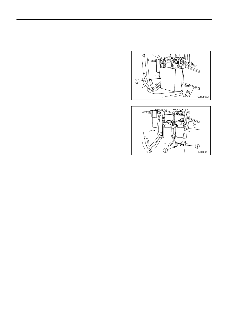
There are two sets of water separators (one each on the left and right), so carry out the inspection and drain the
water in the same way for both the left and right sides.

 1. Check that shut valve (1) on the side of the engine is closed.
 2. Set a container under the water separator to catch the water.

 3. Remove air bleed plug (2) at the top of the water separator.

(Width across flats: 14mm (0.55in))

 4. Loosen drain valve (3) at the bottom of the water separator and

drain the water and fuel into the container.

 5. As soon as the fuel starts to come out from drain hose (4),

tighten drain valve (3).

Tightening torque for drain valve
2

±

0.5 N

·

m {0.2

±

0.05kgf

·

m, 1.4

±

0.4 lbft}

 6. Tighten air bleed plug (2).

Tightening torque for air bleed plug
10

±

2.0N

·

m{1.0

±

0.2kgf

·

m, 7.2

±

1.4 lbft}

Air remains at the top of the filter case, but when the engine is started, the filter case is filled with fuel.

 7. If the inside of filter case (5) is dirty with sediment, wash the case. For details, see "CHECK WATER

SEPARATOR, WASH INSIDE OF FILTER CASE (PAGE 4-42)".

 8. Even during operations, if the level ring inside the water separator rises to the standard line, carry out of the

operation from Step 1 above.

3 - 83

OPERATION

OPERATION

CHECK FUEL LEVEL, ADD FUEL

 WARNING

When adding fuel, never let the fuel overflow.  This may cause a fire. If any
fuel is spilled, wipe it up completely. Never bring flames near fuel because
it is highly flammable and dangerous.

 1. Check the fuel level with fuel gauge (G), which is installed in the

side of the fuel tank.

 2. After completing operations, add fuel through fuel filler (F) to fill

the tank.
Fuel tank capacity: 1300 liters (343.46 US gal)

 3. After adding fuel, tighten the cap ecurely.

REMARK

If the breather hole in the cap (1) becomes clogged, the
pressure inside the tank will go down and the fuel may not flow,
therefore clean the breather hole from time to time.
To prevent air from being sucked into the engine, do not let the
level in the fuel tank go down too low.
Excess fuel in the tank may spill out due to thermal expansion
when the fuel temperature rises. Be careful not to fill with too
much fuel.

CHECK WHEEL HUB NUTS, TIGHTEN

Check for loose wheel hub nuts (1).  If any are found, tighten them.
Tightening torque: 1519 to 1852 N

·

m

{155 to 189kgf

·

m, 1121 to 1367 lbft}

Insert a socket wrench in a pipe, and apply a force of 1568 N (160
kgf) at a point 1 m from the fulcrum to give a tightening torque of
1568 N

·

m (160 kgf

·

m, 1157 lbft).

When tightening the hub nuts after replacing the tires, travel for 5
to 6 km, then check the tightening torque to ensure that there are
no loose bolts.

If any stud bolt used to install the rim is broken, replace all the stud
bolts for that wheel.

3 - 84

OPERATION

OPERATION

CHECK CENTRAL WARNING LAMP, ALARM BUZZER, MONITOR LAMPS AND METERS

Before starting the engine, turn the starting switch to the ON
position, press machine monitor check switch (1), and check that
there is no failure in any monitor lamp.

If any instrument does not work, there is probably a failure, so
please contact your Komatsu distributor for inspection.

CHECK BRAKING EFFECT

Check that the parking brake, foot brake, and retarder brake work properly.
If there is any problem, please contact your Komatsu distributor for repair.

CHECK BRAKING CAPACITY OF SECONDARY BRAKE

 WARNING

If the machine moves, it will lead to serious injury. If machine begins to move during the inspection of braking capacity, lower the
engine speed immediately, set shift lever at N position, and then set parking brake switch at PARKING position.

NOTICE
If inspection is carried out when the body pilot lamp is lighted up and the shift indicator shows "F1", there is danger that the
internal parts of the transmission may be damaged.
Before carrying out inspection, lower the dump body securely and check that the body pilot lamp has gone out, then place the gear
shift lever at the "D" position and check that the shift indicator shows "F2".

Check the braking capacity of the secondary brake as follows.

 1. Stop the machine on flat ground, raise the oil pressure to the

maximum, set the parking brake to TRAVEL, then depress
secondary brake pedal (1).

 2. Set gear shift lever (2) to the D position, gradually raise the

engine speed, and check that the machine does not move
even when the engine reaches full speed.  If the machine does
not move, it is normal.

 3. Lower the engine speed and set the shift lever to "N" position

and  set the parking brake switch to the "PARK" position.

3 - 85

OPERATION

OPERATION

CHECK EMERGENCY STEERING

Check manual emergency steering

 1. Turn starting switch key to the ON position.
 2. Turn emergency steering switch (1) ON, and check that the

steering wheel can be operated.
If the steering wheel cannot be operated, please contact your
Komatsu distributor.

Check auto-emergency steering

 1. Turn the starting switch key to the START position and start the

engine.

 2. Check that the brake oil pressure caution lamp is OFF, then

pull retarder control lever (2) fully and stop the engine.

 3. Turn starting switch key to the ON position.
 4. Check that the emergency steering motor is actuated and the

steering can be operated 1 sec. after parking brake switch (3)
is set to the TRAVEL position.

CHECK BACKUP ALARM

 1. Turn the engine starting switch to the ON position.
 2. Place the gear shift lever in the R position and check that the backup alarm is working.

CHECK ELECTRIC WIRING

 WARNING

If the fuses frequently blow or if there are traces of short circuits in the electrical wiring, locate the cause and immediately
perform repairs, or contact your Komatsu distributor for repairs.
Keep the top surface of the battery clean and check the breather hole in the battery cap.  If it is clogged with dirt or dust, wash
the battery cap to clean the breather hole.

Check for damage and wrong capacity of the fuse and any sign of disconnection or short circuit in the electrical
wiring. Check also for loose terminals and tighten any loose parts.
Check the wiring of the "battery", "starting motor"and "alternator"carefully, in particular.
Always check if there is any accumulation of flammable material around the battery, and remove such flammable
material.
Please contact your Komatsu distributor for investigation and correction of any problems found.

3 - 86

OPERATION

OPERATION

CHECK INFLATION PRESSURE OF TIRES

Measure the inflation pressure with a tire pressure gauge, while the tires are cool, before starting work.
Check for damage or wear to the tires and the rims.
Check for loose wheel hub bolts.
The proper inflation pressure is shown below.

Standard inflation pressure (front wheel and rear wheel)

Tire size

Inflation pressure

27.00R49

""

 (standard)

0.69MPa {7.00kgf/cm

2

, 99.4PSI}

31/90R49

""

 (if equipped)

0.69MPa {7.00kgf/cm

2

, 99.4PSI}

NOTICE
If the tires are used when the inflation pressure is less than the value given in the table above, the rim may be damaged.
Always keep the tire inflation pressure within +0 to +0.03 MPa {0.3 kgf/cm

2

, 4.3 PSI} of the value in the table above.

DOES BODY POSITIONER OPERATE NORMALLY?

 1. Turn the starting switch key to the START position and start the

engine.

 2. Operate the dump control lever to the RAISE position, then

release it.
Check that the dump body stops before the end of the stroke.

REMARK

If the dump body reaches the end of the stroke, the contact of the
body will cause an impact. The body positioner is functioning, so
the dump body stops without any impact.

3 - 87

OPERATION

OPERATION

CHECK MACHINE MANAGEMENT SYSTEM (VHMS)

To maintain function and performance of the machine management system (VHMS), perform the following daily
checks. If any abnormality is found, contact your Komatsu distributor.

 1. Check for loose, damaged, or dirty mounts of the sensors or antenna.
 2. Check for disconnected or damaged wiring harnesses, cables, or connectors.
 3. Check for oil or gas leaks from the sensor mounts.

Inspect the following places.
Communication antenna (1) (if equipped)
Antenna pole (2) (if equipped)

VHMS controller (3)

Orbcomm controller (4) (if equipped)

3 - 88

OPERATION

OPERATION

OPERATION

OPERATION

Download connector (5)
This is behind the assistant's seat.

Ground level download box (6)

Blow-by sensor (7)

Engine oil temperature sensor (8)
Engine oil filter (9)

3 - 89

OPERATION

OPERATION

OPERATION

OPERATION

Exhaust temperature sensor (10)

Ambient temperature sensor (11)
Ambient temperature sensor (11) is inside box (A).
Remove box (A) when carrying out inspection.

3 - 90

OPERATION

OPERATION

ADJUSTMENT BEFORE OPERATION

ADJUSTING OPERATOR'S SEAT

 WARNING

Park the machine in a safe place and stop the engine when carrying out adjustment of the operator's seat.
Adjust the seat before starting operations or when changing operators.
Adjust the position of the operator's seat so that you can depress the brake pedal fully with your back against the seat backrest.

(A) Fore-and-aft adjustment
Pull lever (1) up, set the seat to the desired position, then release
the lever.
Amount of adjustment: 180 mm (7.1 in)

(10 mm (0.4 in) x 18 stages)

(B) Adjusting seat angle
Move lever (2) up and push down on the rear of the seat to tilt it
backward.
Move lever (2) down and push down on the front of the seat to tilt
it forward.
Adjustment range: 13 degrees (Tilt forward/tilt back angle)

(C) Setting seat for operator's weight
Turn grip (3) to adjust the strength of the suspension.
Adjustment range: (Target) 50 to 120 kg (110 to 265 lb)

(D) Adjusting backrest angle
Move lever (4) up and move the backrest to the front or rear.
When doing this, keep your back pressed against the seat back.
If your back is not against the seat back, the seat back may spring back suddenly.
Adjustment range: 66

°

 to the front (3

°

 x 22 stages)

72

°

 to rear (3

°

 x 24 stages)

(E) Seat height adjustment
Move lever (2) up/down, then move the seat up or down as desired.  Since lever (2) is also used for adjusting seat
angle, set the seat to the desired height while adjusting the angle.
Adjustment range: 60 mm (2.4 in)

3 - 91

OPERATION

OPERATION

(F) Adjusting headrest height
Move the headrest up and down to the desired height.
Adjustment range: 50 mm (2.0 in)

(G) Adjusting headrest angle
Rotate the headrest to the front or rear.

(H) Lumbar support
Turn grip (5) to adjust the tension applied to the lower back.

ADJUST SEAT BELT

 WARNING

Before fastening the seat belt, check that there is no problem in the securing brackets or belt.  If there is any wear or damage,
replace.
Even if there appears to be no problem in the seat belt, replace the seat belt once every 3 years.  The date of manufacture is
woven on the reverse side of the belt.
Adjust and fasten the seatbelt before starting to travel.
Always use the seatbelt when traveling.
Do not use the seat belt with either half of the belt twisted.

Fastening and removing belt

Fasten the belt so that it is tight without being too tight.

 1. Sit on the seat, depress the brake pedal fully, and adjust the

seat so that your back is pressed against the backrest.

 2. Sit in the seat, pull the right side of the belt, then insert tongue

(1) into buckle (2) until a click is heard.

 3. When removing the belt, press the red button in buckle (2) to

free the belt.
Fit the belt so that it follows your body and is not twisted.

3 - 92

OPERATION

OPERATION

ADJUST STEERING WHEEL TILT

 WARNING

Always stop the machine before adjusting the tilt of the steering wheel.

The tilt of the steering wheel can be adjusted to the front and rear,
and up and down. Pull lever up and set the steering wheel to the
desired position, then push lever down to lock the steering wheel
securely in position.

Amount of adjustment: Front/rear: 80 mm/80 mm (3.2 in/3.2 in)

(from center of steering wheel)
Up: 33 mm (1.3 in)
Down: 17 mm (0.7 in)

3 - 93

OPERATION

OPERATION

ADJUSTING MIRROR

 WARNING

Be sure to adjust the mirrors before starting work. If they are not adjusted properly, you cannot secure the visibility and may be
injured or may injure someone seriously.

Loosen the bolt and nut installing the mirror, then adjust the mirror
to a position which gives the best view from the operator's seat.

When installing the mirror, adjust so that it is possible to see part
of the machine, together with any person (or any object of a
height of 1.5 m (4 ft 11 in) and diameter of 30 cm (11.8 in)) at the
front, rear, left, or right of the machine.
The values below are reference values for the range of visibility.

Mirror A: It has to reflect the portion beyond shaded area (A), an

area around tire ground contact point (A') and dump body
upper end.

Mirror B: It has to reflect shaded area (B).
Mirror C: It has to reflect shaded area (C) and part of the truck.
Mirror D: It has to reflect the portion beyond shaded area (D), an

area around tire ground contact point (D') and dump body
upper end.

Mirror E: It has to reflect the portion beyond shaded area (E) and

part of the dump body.

3 - 94

OPERATION

OPERATION

OPERATIONS, CHECKS BEFORE STARTING

 WARNING

When starting the engine, check that the shift lever is set in the N
(neutral) position and that the parking brake switch is at PARKING
position.
Before standing up from the operator's seat, place the shift lever at N
(neutral) position, and set the parking brake switch to the PARKING
position.

 1. Check that parking brake switch (1) is in the PARKING

position.

 2. Check that gear shift lever (2) is at the N position.

REMARK

If the starting switch is turned to the ON position when the shift
lever is not at the N position, the shift lever position pilot lamp and
central warning lamp will flash, and the alarm buzzer will sound.

 3. Check that dump lever (3) is at the HOLD position.

3 - 95

OPERATION

OPERATION

OPERATION

OPERATION

 4. Check that retarder control lever (4) is at the RELEASED

position.

 5. Check that there is no problem in the machine monitor when

starting switch (5) is turned to the ON position.

3 - 96

OPERATION

OPERATION

STARTING ENGINE

 WARNING

Start the engine only after sitting down in the operator's seat.
Do not attempt to start the engine by short-circuiting the engine starting circuit. Such an act may cause a serious bodily injury
or fire.
Check that there are no persons or obstacles in the surrounding area, then sound the horn and start the engine.
Never use starting aid fluids as they may cause explosions.
Exhaust gas is toxic. When starting the engine in confined spaces, be particularly careful to ensure good ventilation.

NOTICE

Do not accelerate the engine sharply until it is warmed up.
Do not operate the starting motor continuously for more than 20 seconds.
If the engine fails to start, wait for 2 minutes or so, and then try to start again.
When starting the engine, do not depress the accelerator pedal. Even if the accelerator pedal is depressed just after the engine
is started, the engine speed is limited by the turbo protect function. After the turbo protect time, however, the engine speed
rises sharply and the turbocharger may be damaged.

 1. Turn the key of starting switch (1) to the ON position.

The preheater pilot lamp lights up, depending on the engine
water temperature, and the engine is preheated. After the
pre-heating time, the preheater pilot lamp goes off.

The pre-heating times are as shown below.

Engine water temperature

Preheating time

Above -5

°

C (23

°

F)

-

-5

°

C to -20

°

C (23

°

F to -4

°

F)

20 to 45 sec

Below -20

°

C (-4

°

F)

45 sec

REMARK

When the key of the starting switch is turned to the ON position, if the engine water temperature is -5

°

C or higher,

the engine is not pre-heated. At this time, the engine can be started without pre-heating operation.

3 - 97

OPERATION

OPERATION

OPERATION

OPERATION

 2. After the preheater pilot lamp goes off, turn the key of the

starting switch to the START position, and the engine will start.

REMARK

When starting the engine, the monitor may flash while the starting
motor is turning, but if the monitor lamp goes out after the engine
is started, there is no problem.

 3. After the engine starts, release the key of the starting switch.

REMARK

If the engine fails to start, return the key of the starting switch to the
OFF position, and then start the operation again from step 1. If the
starting switch is not returned to the OFF position, the automatic
preheater does not operate.

 4. Just after the engine starts, do not depress the accelerator pedal but run the engine idle at low speed for at least

15 seconds.
When the engine is started for the first time after the engine oil or engine oil filter is replaced, continue the low
idle run for at least 20 seconds to circulate the engine oil in the engine.

REMARK

Since the turbocharger rotates at very high speed, it is seized if not lubricated well. To prevent this, the turbo
protect mechanism works for a certain time just after the engine starts, depending on the engine water
temperature.

Engine water temperature

Turbo protect time

Above 10

°

C (50

°

F)

0 sec

-10

°

C to 10

°

C (14

°

F to 50

°

F)

0 to 25 sec

Below -10

°

C (14

°

F)

25 sec

Just after the engine starts, the injection characteristics are changed for a certain time to keep the low idle speed
a little high, depending on the engine water temperature. The engine acceleration characteristics are also
changed so that the engine will be accelerated moderately.

Engine water temperature

Injection characteristics

change time

Above 20

°

C (68

°

F)

0 sec

0

°

C to 20

°

C (32

°

F to 68

°

F)

0 to 6 sec

-20

°

C to 0

°

C (-4

°

F to 32

°

F)

6 to 12 sec

-30

°

C to -20

°

C (-22

°

F to -4

°

F)

12 to 15 sec

3 - 98

OPERATION

OPERATION

BREAKING-IN THE MACHINE

NOTICE
Your Komatsu machine has been thoroughly adjusted and tested before shipment. However, operating the machine under severe
conditions at the beginning can adversely affect the performance and shorten the machine life.
Be sure to break-in the machine for the initial 100 hours (as indicated by the service meter).
During break-in operations, follow the precautions described in this manual.

Idle the engine for 5 minutes after starting it up.
Avoid operation with heavy loads or at high speeds.
Immediately after starting the engine, avoid sudden starts, sudden acceleration, unnecessary sudden stops, and
sudden changes in direction.

OPERATIONS, CHECKS AFTER STARTING ENGINE

WARMING-UP OPERATION

NOTICE

Avoid accelerating the engine suddenly before the warming-up operation is completed.
Do not run the engine for more than 20 minutes at low idling or high idling.
If it is necessary to idle the engine, apply a load from time to time or run at a mid-range speed.
With the auto emergency steering system, if the warming-up operation has not been carried out thoroughly and the parking
brake switch is set to TRAVEL, the emergency steering may be actuated momentarily when the dump control lever is operated.

After starting the engine, do not immediately start operations. First, perform the following operations and checks.

 1. After starting the engine, run the engine at idle for 5 minutes for warming up operation.
 2. After the warming-up operation, check that the machine monitor is normal.

If there is any problem, carry out maintenance or repair.
When the AISS LOW switch is at the AUTO position and the engine water temperature is still low, high idle
revolution is automatically maintained.

 3. Check if there is no problem in the steering operation, flashing of lights, sound of horn, exhaust gas color, noise,

or vibration. If any problem is found, repair it.
When the steering oil temperature is low, the steering will become slightly heavier, so avoid operating the
steering when traveling at high speed.

3 - 99

OPERATION

OPERATION

STOPPING ENGINE

NOTICE
If the engine is suddenly stopped without allowing it to cool down, there is
danger that the life of the engine parts will be shortened, so never stop the
engine suddenly except in emergency.
Allow the engine to cool down gradually before stopping it.

 1. Set the shift lever to the N position, then set the parking brake

switch to the PARKING position.

 2. Lower the dump body and set the dump lever to the HOLD

position.

 3. Run the engine at low idle for about 5 minutes to cool down

gradually.

 4. Turn the key of starting switch (1) to the OFF position to stop

the engine.

 5. Remove the key from starting switch (1).

CHECKS AFTER STOPPING ENGINE

 1. Walk around the machine and check the dump body, body work, and undercarriage, and check also for leakage

of oil and water.

 2. Fill the fuel tank.
 3. Check the engine compartment for paper and debris. Clean out any paper and debris to avoid a fire hazard.
 4. Remove any mud affixed to the undercarriage.

3 - 100

OPERATION

OPERATION

MOVING MACHINE OFF (FORWARD, REVERSE), STOPPING

MOVING MACHINE FORWARD

 WARNING

When moving the machine off, check that the area around the machine
is safe, then sound the horn before starting.
Do not allow people to get near the machine.
Clear the machine's travel path of any obstacle.
Pay a particular attention to the blind spot at the rear of the machine,
when traveling the machine in reverse.

 1. Check that there is no warning display on the machine monitor.
 2. Fasten the seatbelt.
 3. Check that dump lever (1) is at the FLOAT position and that the

dump body pilot lamp is out.  
If the dump body pilot lamp is lighted up, operate the dump
lever to the HOLD position, then operate it to the FLOAT
position to cancel the dump body HOLD condition.

REMARK

When the engine is started, the dump lever is at the FLOAT
position, but the dump body is at HOLD.

 4. Depressed the brake pedal fully.   Then set parking brake

switch (2) to the TRAVEL position to release the parking brake.

REMARK

If the engine is stopped with the parking brake switch at TRAVEL,
the parking brake will be applied automatically even though the
parking brake switch is at TRAVEL.   When starting the engine
again, operate the parking brake switch to PARKING, and then
move it back to TRAVEL to cancel the parking brake.

3 - 101

OPERATION

OPERATION

OPERATION

OPERATION

 5. Check that retarder pilot lamp (3) is not lighted up, then set shift

lever (4) to the desired position.

NOTICE

When operating the shift lever, be sure to set it in position securely.
If the lever is not placed in position properly, the shift position display
on the panel may go out and the Transmission system caution lamp
may light up.
Always release the accelerator pedal before shifting from N to R or F.

 6. Depress accelerator pedal (5) to move the machine off.

NOTICE

If the shift lever is shifted to a position other than N when the parking
brake has not been released, the central warning lamp will flash and the
alarm buzzer will sound.
If the shift lever is shifted to a position other than N when the dump lever
is at a position other than FLOAT or the body is raised, the central
warning lamp will flash and the alarm buzzer will sound.
Do not operate the shift lever with the accelerator pedal depressed.  The
throttle is automatically throttled, but a big shock is generated, and will
also reduce the service life of the machine.

3 - 102

OPERATION

OPERATION

MOVING MACHINE IN REVERSE

 WARNING

When switching between FORWARD and REVERSE, check that the new
direction of travel is safe.
There is a blind spot behind the machine, so use extreme caution when
reversing the machine.
Always stop the machine completely before shifting between
FORWARD and REVERSE.

There are two speed ranges when traveling in reverse: RL and RH.
Either of these can be selected with the machine monitor.
For details of the method of switching between RL and RH, see
"METHOD OF SWITCHING BETWEEN RL AND RH (PAGE
3-31)".
The selected speed range is displayed on the shift indicator.

Place gear shift lever (1) in the R position, then gradually depress
accelerator pedal (2) to move the machine off.

REMARK

The machine cannot travel in reverse when the dump body is
raised. Lower the dump body, set the dump lever to the FLOAT
position, then set the gear shift lever to the R position.
If the gear shift lever is set to the R position when the machine
is traveling forward at a speed of 4 km/h (2.5MPH) or more, the
transmission is placed in Neutral until the travel speed is
reduced, the brake is automatically applied, and the engine is
also throttled.

NOTICE

When shifting between FORWARD and REVERSE, stop the machine
completely, and run the engine at low idle when shifting the lever.  After
moving the gear shift lever, do not depress the accelerator until you
detect that the transmission clutch has engaged.
Do not operate the gear shift lever with the accelerator pedal depressed.
This will cause a big shock, and will also reduce the service life of the
machine.

3 - 103

OPERATION

OPERATION

STOPPING MACHINE

 WARNING

Avoid stopping suddenly. Give yourself ample room when stopping.
If the foot brake is used repeatedly or is kept depressed for a long time,
the brake may overheat and its life will be shortened.
If the parking brake is used to stop the machine, the brake will be
damaged. Do not use the parking brake except when stopping in
emergencies or when parking the machine after stopping it.

NORMAL STOPPING

Release accelerator pedal (1), and depress brake pedal (2) to stop
the machine.

3 - 104

OPERATION

OPERATION

STOPPING IN EMERGENCY

If there should be a failure in the foot brake, stop the machine as
follows.

 WARNING

When the machine stops, put blocks under the tires immediately.

 1. Pull retarder control lever (1) fully to apply the retarder.

 2. If operating only the retarder control lever gives insufficient

braking force, depress secondary brake pedal (2) to stop the
machine.
The secondary brake applies the front and rear parking brakes.

REMARK

If the machine is stopped with the secondary brake, the central
warning lamp will flash and the alarm buzzer will sound. If this
happens, return the gearshift lever to the N position to cancel the
warning lamp and alarm buzzer.

 3. When the machine stops, set parking brake switch (3) to the

PARKING position.

 4. If an emergency stop has been made, put blocks under the

tires immediately, then try to find the cause, and repair it on
site.

3 - 105

OPERATION

OPERATION

SHIFTING GEAR

 WARNING

Do not move the gear shift lever to the N position when the machine is traveling or when it is traveling down a slope. Always place
the transmission in gear before traveling.

If the transmission is in Neutral, the engine cannot provide any braking effect and the steering wheel will become heavier. In
addition, there will be lack of cooling oil for the retarder, so there is danger that it will overheat or that the actuation of the brake
will be poor.
There may also be damage to the transmission or other parts of the power train, and there is danger of unexpected accidents.

When shifting gear, do as follows.
This machine has an automatic transmission, so set gear shift
lever (1) to the desired position, and the transmission will
automatically shift to a position to match the travel speed.
Regardless of the position of the gear shift lever, if the dump body
is raised, the speed range is set to 1st. Always lower the dump
body when traveling.

NOTICE

When shifting between FORWARD and REVERSE, stop the machine
completely, and run the engine at low idle when shifting the lever.  After
moving the shift lever, do not depress the accelerator until you detect
that the transmission clutch has engaged.
Do not operate the shift lever with the accelerator pedal depressed.  The
throttle is automatically throttled, but a big shock is generated, and will
also reduce the service life of the machine.

SHIFTING UP

 1. When accelerator pedal (2) is depressed to accelerate the

machine, the lockup clutch is engaged to shift the transmission
to direct drive.

 2. If the machine is accelerated further, the transmission will

automatically shift up.

3 - 106

OPERATION

OPERATION

SHIFTING DOWN

If accelerator pedal (2) is released, the machine speed will be
reduced, and the transmission will automatically shift down.

DOWN SHIFT INHIBIT

If the shift lever is operated when the machine is traveling, and the travel speed is faster than the maximum speed
for each gear position, the transmission is not shifted immediately but is shifted down when the travel speed drops.
This prevents overrunning of the engine.

SHIFTING DOWN WHEN USING FOOTBRAKE

If the foot brake is used to reduce speed and the transmission is at a position between 2nd and 4th, the transmission
does not shift down until the brake is released or until the machine travel speed goes down to the travel speed for
the 2nd speed range. By holding the speed range, the gear speed is shifted fewer times and the transmission shock
is reduced.

SKIP SHIFT

For normal gearshifting, the transmission shifts one gear range at a time.
When traveling uphill and the travel speed drops suddenly, the transmission jumps one gear range when shifting
down to reduce the transmission shock.

OVERRUN PREVENTION DEVICE

If the engine tachometer enters the red range during operations, the alarm buzzer will sound and the central warning
lamp will light up at the same time, so lower the engine speed and the travel speed.  If the machine is accelerated
to a speed higher than the maximum speed set for each range of the shift lever, the overrun prevention device is
actuated to apply the retarder and reduce the travel speed.

3 - 107

OPERATION

OPERATION

TRAVELING DOWNHILL

When traveling downhill, travel at a safe speed which matches the width of the road, the condition of the road
surface, and other conditions of the jobsite.

 WARNING

When the machine stops, put blocks under the tires immediately.
For details of the maximum permitted speed when traveling downhill with the retarder operated, see the brake performance
graph for the downhill distance and grade.
It is dangerous if the machine travels downhill at a speed greater than the maximum permitted speed on the brake performance
graph. This may damage the retarder brake.
If the retarder oil temperature caution lamp on the machine monitor lights up when the retarder is being used to travel downhill,
shift the transmission down.
(When the caution lamp lights up, the central warning lamp also lights up and the alarm buzzer sounds.)
If the caution lamp does not go out even when the transmission is shifted down, stop the machine, return the gear shift lever
to the Neutral position, run the engine at 1900 rpm, and wait for the caution lamp to go out.
If the retarder stops having any effect when the machine is traveling downhill with the retarder operated, do as follows.
1. Release the retarder control lever fully, then operate the retarder control lever again.
2. If the retarder still does not work even when the retarder control lever is operated again, release the retarder control lever
fully.
Then depress the brake pedal, stop the machine, and ask your Komatsu distributor to carry out repairs.
Operate the retarder gradually. If it is operated suddenly, there is danger that the tires may slip.
Do not move the gear shift lever to the N position when the machine is traveling or when it is traveling down a slope. Always
place the transmission in gear before traveling.

If the transmission is in Neutral, the engine cannot provide any braking effect and the steering wheel will become heavier.

In addition, there will be lack of cooling oil for the retarder, so there is danger that it will overheat or that the actuation of the
brake will be poor.

There may also be damage to the transmission or other parts of the power train, and there is danger of unexpected accidents.

NOTICE

If the retarder control lever is operated when traveling downhill, the transmission can be shifted down sooner than with normal
deceleration. It is also possible to travel without shifting up.
Do not accelerate or shift up when using the retarder. The engine speed will rise and this may cause the alarm buzzer to sound
and the central warning lamp to flash.

3 - 108

OPERATION

OPERATION

OPERATION

OPERATION

 1. Before starting to travel downhill, release accelerator pedal (1)

and operate retarder control lever (2) to slow the machine
down.

 2. Move the shift lever to a position (6, 5, 4, 3, 2) that matches the

maximum

permissible

speed

for

the

retarder

brake

performance.

 3. When traveling downhill, operate retarder control lever (2), run

the engine at a speed of at least 1800 rpm, and travel so that
the retarder brake oil temperature gauge is in the white range.

REMARK

If the pedal is released when traveling downhill, the engine may make a peculiar noise, but there is no problem with
quality or durability.

For machines equipped with an exhaust brake, using the exhaust brake can provide more secure braking force for
increased safety, and will also improve the durability of the brake.
For details of handling the exhaust brake, see "EXHAUST BRAKE SWITCH (PAGE 3-40)".

3 - 109

OPERATION

OPERATION

ARSC (AUTOMATIC RETARDER SPEED CONTROL)

When traveling downhill, if the switch is pressed at the speed that is to be maintained, the retarder is automatically
actuated to prevent the travel speed from exceeding the set speed, so this makes retarder operations easy.

 WARNING

The ARSC system is actuated when the auto retarder (ARSC) switch is at the ON position.
Before starting down the hill, check that a suitable set speed is displayed on the auto retarder set travel speed indicator and
that the auto retarder READY pilot lamp is lighted up.
If the speed is set to a speed that exceeds the maximum permissible speed obtained from the brake performance graph, there
is danger that there will be overheating and that the retarder brake may be damaged. Always set the speed so that it does not
exceed the maximum permissible speed.
When the ARSC is actuated on slippery road surfaces, the wheels may lock. If this happens, make less use of the ARSC.
If any abnormality occurs in the system and braking cannot be carried out properly, the alarm sounds and the system is turned
OFF to cancel the ARSC. If necessary, control the machine with the retarder control lever and foot brake to stop the machine
in a safe place, then turn the auto retarder (ARSC) switch OFF.

3 - 110

OPERATION

OPERATION

EXPLANATION OF COMPONENTS

(1)
(2)
(3)
(4)
(5)

Auto retarder (ARSC) switch
Auto retarder (ARSC) set lever
Auto retarder set speed indicator
Central warning lamp
Retarder control lever

(6)
(7)
(8)
(9)

Accelerator pedal
Brake pedal
Auto retarder READY pilot lamp
Retarder pilot lamp

(A) Set
(B) Increase speed

(C) Decrease speed
(D) Cancel

AUTO RETARDER (ARSC) SWITCH

This switch (1) is used to turn the ARSC system ON/OFF.

AUTO RETARDER (ARSC) SET LEVER

This lever (2) is used in the following cases:
When setting the travel speed
When making fine adjustments to the set speed (tap up/tap down)
When canceling the speed setting

AUTO RETARDER SET SPEED INDICATOR

This display (3) shows the speed (km/h (MPH)) that has been set.
When the auto retarder (ARSC) switch is turned OFF, the display goes out.
It displays 0 when the set travel speed is canceled.
When the starting switch is turned ON or the auto retarder (ARSC) switch is ON, the previously set travel speed is
displayed.

3 - 111

OPERATION

OPERATION

CENTRAL WARNING LAMP

This lamp (4) lights up if there is a serious problem in the ARSC system when the auto retarder (ARSC) switch is
ON.

RETARDER CONTROL LEVER

Even when the ARSC is in operation, the retarder can be operated with this lever (5).
During operation of the ARSC, there is greater play when the lever starts to be pulled.   If the retarder lever is
operated suddenly (pulled too much), the brakes will be applied suddenly.

ACCELERATOR PEDAL

The ARSC is actuated only when the accelerator pedal (6) is not being pressed.

BRAKE PEDAL

This pedal (7) operates the wheel brake even when the ARSC is being operated.

AUTO RETARDER READY PILOT LAMP

When this lamp (8) is lighted up, it shows that operation of the ARSC is possible at the set travel speed.  When it
is out, the ARSC is not actuated.
It lights up for 3 seconds when the starting switch is turned ON to check the bulb.

RETARDER PILOT LAMP

This lamp (9) lights up when the retarder is operated, even when the ARSC is being operated.

3 - 112

OPERATION

OPERATION

METHOD OF OPERATION

ACTION OF ARSC SYSTEM

The ARSC system is actuated when the auto retarder (ARSC) switch is ON.
When the set switch of the auto retarder (ARSC) set lever is pressed, the travel speed at that point is set as the
downhill travel speed.  When traveling downhill, if the machine attempts to exceed the set travel speed, the retarder
is automatically actuated.
The set travel speed is displayed on the auto retarder set speed indicator and is saved in memory.
If the accelerator is depressed during operation of the ARSC, the ARSC is canceled and the speed increases.
If the brake pedal or retarder control lever are operated while the ARSC is being operated, it is possible to reduce
the speed or stop the machine in the same way as during normal operation of the brakes.
If the set travel speed is near the gear shifting point or there is a change in the grade of the slope, the transmission
may shift (shift up or shift down) even when the ARSC is being operated.
The time taken for the machine travel speed to match the set speed may differ according to the grade of the slope.
There may also be a slight difference between the set travel speed and the speed displayed on the speedometer.

METHOD OF SPEED SETTING

 WARNING

If the speed is set to a speed that exceeds the maximum permissible speed obtained from the brake performance graph, there is
danger that there will be overheating and that the retarder brake may be damaged. Always set the speed so that it does not exceed
the maximum permissible speed.

If the actual machine speed during the setting operation is less than 10 km/h (6.2 MPH), the speed is set to 10 km/h
(6.2 MPH).  If it is higher than 55 km/h (34.2 MPH), it is set to 55 km/h (34.2 MPH).  In all other cases, it is set to the
actual travel speed.
The travel speeds that can be set depend on the selection of the gearshift lever as follows.
When the gearshift lever is at the D, 6, 5, 4, 3, 2, or L positions, the range for the set speed is 10 to 55 km/h (6.2 to
34.2 MPH).
It is impossible to set the speed when the gearshift lever is at the N or R positions.

METHOD OF CARRYING OUT FINE ADJUSTMENT OF SET TRAVEL SPEED

When it is desired to raise the set travel speed by 1 km/h (tap up), move the auto retarder (ARSC) set lever up once.
When it is desired to lower the set travel speed by 1 km/h (tap down), move the auto retarder (ARSC) set lever down
once.

REMARK

Release the auto retarder (ARSC) set lever after changing the set travel speed.
If the set switch and cancel are operated at the same time, the cancel operation is given priority.
If the set switch and tap up are operated at the same time, the tap up operation is given priority.
If the set switch and tap down are operated at the same time, the tap down operation is given priority.
The tap up and tap down operations are used for making fine adjustment of the set travel speed.
It is possible to adjust the set travel speed up to

±

 5 km/h (3.1 MPH) when traveling in ARSC (when the accelerator

pedal is released). When the accelerator pedal is being depressed, the ARSC is canceled, so it is possible to
operate freely in a range from 10 to 55 km/h (from 6.2 to 34.2 MPH).

3 - 113


Content      ..     3      4      5      6     ..