Galeo HD785-7 DUMP TRUCK. Operation and Maintenance Manual (2006) - page 3
 

  Index      Manuals     Galeo HD785-7 DUMP TRUCK. Operation and Maintenance Manual (2006)


Search            copyright infringement  


Content      ..     1      2      3      4      ..


Galeo HD785-7 DUMP TRUCK. Operation and Maintenance Manual (2006) - page 3


OPERATION

EXPLANATION OF COMPONENTS

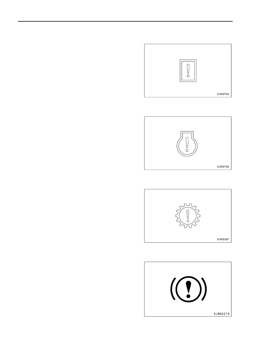
MACHINE MONITOR, OPTION SYSTEM CAUTION LAMP

This monitor (9) lights up when a problem has been detected in the
machine monitor or in the system for an installed option.
When it lights up, "E03 CHECK RIGHT NOW" is displayed on the
character display at the same time, so stop the machine
immediately at a safe place, then stop the engine and carry out
inspection.

ENGINE SYSTEM CAUTION LAMP

This monitor (10) lights up when a problem has been detected in
the system controlled by the engine controller.
When it lights up, "E03 CHECK RIGHT NOW" is displayed on the
character display at the same time, so stop the machine
immediately at a safe place, then stop the engine and carry out
inspection.

TRANSMISSION SYSTEM CAUTION LAMP

This monitor (11) lights up when a problem has been detected in
the system controlled by the transmission controller.
When it lights up, "E03 CHECK RIGHT NOW" is displayed on the
character display at the same time, so stop the machine
immediately at a safe place, then stop the engine and carry out
inspection.

RETARDER SYSTEM CAUTION LAMP

This monitor (12) lights up when a problem has been detected in
the system controlled by the retarder controller.
When it lights up, "E03 CHECK RIGHT NOW" is displayed on the
character display at the same time, so stop the machine
immediately at a safe place, then stop the engine and carry out
inspection.

3 - 18
OPERATION

EXPLANATION OF COMPONENTS

METER DISPLAY PORTION

PILOT DISPLAY PORTION

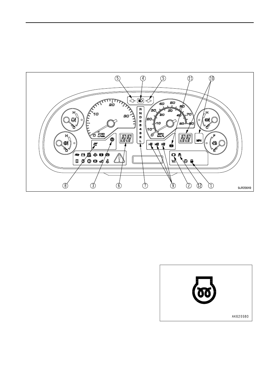
When starting switch is ON, the pilot display lights up when display items are functioning.

(1)
(2)
(3)
(4)
(5)
(6)

Engine pre-heating pilot lamp
Retarder pilot lamp
Lockup pilot lamp
Head lamp high beam pilot lamp
Turn signal pilot lamp
Shift indicator

(7)
(8)
(9)

(10)
(11)
(12)

Shift lever position pilot lamp
Power mode pilot lamp
Auto suspension mode pilot lamp (if equipped)
Auto retarder set speed indicator
Auto retarder ready pilot lamp
Exhaust brake pilot lamp (if equipped)

ENGINE PRE-HEATING PILOT LAMP

This monitor (1) lights up when the electrical heater for pre-heating
the engine is being actuated. When the starting switch is turned to
the ON position in cold weather, the monitor lights up. It goes out
after 20 to 45 seconds to indicate that the pre-heating has been
completed.

3 - 19

OPERATION

EXPLANATION OF COMPONENTS

RETARDER PILOT LAMP

This monitor (2) lights up when the retarder control lever is pulled
and the retarder is actuated.

LOCKUP PILOT LAMP

This monitor (3) lights up when the torque converter lockup is
engaged and the transmission is shifted to direct drive.

HEAD LAMP HIGH BEAM PILOT LAMP

This monitor (4) lights up when the head lamps are set to high
beam.

TURN SIGNAL PILOT LAMP

This monitor (5) flashes at the same time as the turn signal lamp
flashes.

3 - 20

OPERATION

EXPLANATION OF COMPONENTS

SHIFT INDICATOR

This monitor (6) shows the transmission shift range (speed range).

SHIFT LEVER POSITION PILOT LAMP

This monitor (7) displays the position of the shift lever.
The letter or number for the speed range selected by the shift lever
lights up.

POWER MODE PILOT LAMP

This monitor (8) displays the power mode.
This monitor lights up when the high power mode is used.

3 - 21

OPERATION

EXPLANATION OF COMPONENTS

AUTO SUSPENSION MODE PILOT LAMP

(If equipped)
This monitor (9) displays the suspension mode, when the machine
is equipped with the suspension controller.
On machines equipped with an automatic suspension system, the
suspension

system

automatically

switches

the

damping

characteristics of the suspension according to the size of the load,
use of the brake, operation of the steering, and operation of the
dump control.
Normally it is set to the soft mode when the dump truck is traveling
empty and to the medium mode when it is traveling loaded. When
the foot brake is operated or the machine is suddenly turned, or the
dump control is operated, the suspension mode is switched to
insure the stability of the machine to the front and rear, and left and
right.

H : Hard mode
M : Medium mode
S : Soft mode

AUTO RETARDER SET SPEED INDICATOR

This monitor (10) displays the set travel speed for the auto retarder
speed control (ARSC).
When the auto retarder (ARSC) switch is OFF, the monitor goes
out.  If the set travel speed has been canceled, 0 is displayed.

AUTO RETARDER READY PILOT LAMP

This monitor (11) shows that the auto retarder speed control can be
actuated at the set travel speed.
When the monitor is OFF, the auto retarder speed control is not
actuated.

3 - 22

OPERATION

EXPLANATION OF COMPONENTS

EXHAUST BRAKE PILOT LAMP

(If equipped)
The pilot lamp in this monitor (12) lights up when the exhaust brake
is applied.

3 - 23

OPERATION

EXPLANATION OF COMPONENTS

METERS

(1)
(2)
(3)

Speedometer
Engine tachometer
Fuel gauge

(4)
(5)
(6)

Engine water temperature gauge
Torque converter oil temperature gauge
Retarder oil temperature gauge

SPEEDOMETER

This meter (1) indicates the travel speed of the machine.

3 - 24

OPERATION

EXPLANATION OF COMPONENTS

ENGINE TACHOMETER

This meter (2) shows the engine speed.
If the gauge indicator the red range during operations, the alarm
buzzer will sound and the central warning lamp will light up at the
same time, so reduce the engine speed and the machine travel
speed.

FUEL GAUGE

This meter (3) shows the amount of fuel remaining in the fuel tank.
When the fuel level caution lamp lights up, it indicates that there is
less than 225 liters (59.45 US gal) of fuel remaining in the tank, so
check and add fuel.

ENGINE WATER TEMPERATURE GAUGE

This meter (4) indicates the engine water temperature.
It should be in the white range during operation.
If it is in the red range during operation, the alarm buzzer will sound
and the central warning lamp will light up at the same time.  "E02
ENGINE OVERHEAT" is displayed on the character display, so
run at the engine under no load at a mid-range speed and wait until
the meter enters the white range.
If it is in the red range, the engine output is automatically limited.

TORQUE CONVERTER OIL TEMPERATURE GAUGE

This meter (5) indicates the torque converter oil temperature.
It should be in the white range during operation.
If it is in the red range during operation, the alarm buzzer will sound
and the central warning lamp will light up.  "E02 TC OVERHEAT"
is displayed on the character display, so run the engine under no
load at a mid-range speed and wait until the meter enters the white
range.

3 - 25

OPERATION

EXPLANATION OF COMPONENTS

RETARDER OIL TEMPERATURE GAUGE

This meter (6) indicates the retarder oil temperature.
It should be in the white range during operation.
If it is in the red range during operation, the alarm buzzer will sound
and the central warning lamp will light up at the same time.  "E02
BRAKE OVERHEAT" is displayed on the character display, so
stop the machine in a safe place, set the shift lever to the N
position, run the engine under no load at a mid-range speed and
wait until the lamp goes out.

CENTRAL WARNING LAMP

If the machine is in the following condition, this lamp will flash, and
at the same time, the alarm buzzer will sound intermittently.

When a problem has occurred in any of "EMERGENCY STOP
ITEM (PAGE 3-15)".
When action code "E02" or "E03" is displayed on the character
display.
If the parking brake is applied, but the shift lever is not at the N
position.
When the dump lever is not at the FLOAT position or the dump
body is raised and the shift lever is not at the N position.
When the engine tachometer indicates the red range.

3 - 26

OPERATION

EXPLANATION OF COMPONENTS

OTHER FUNCTIONS OF MACHINE MONITOR

DISPLAY METHOD FOR REVERSE TRAVEL ODOMETER

Use this when checking the total travel distance in reverse.

 1. Check that the character display is showing the service meter/odometer, or the action code.  If it is giving any

other display, turn the starting switch OFF, then turn the starting switch to the ON position and wait for the above
display to be given.

 2. Press the (

"

) of machine monitor mode selector switch 1.  It

displays the overall distance traveled in reverse.

 3. When completing the operation, press (

!

) of machine monitor

mode selector switch 1 or turn the starting switch  OFF.

3 - 27

OPERATION

EXPLANATION OF COMPONENTS

RESET METHOD FOR FILTER, OIL REPLACEMENT TIME

The filter and oil replacement time is displayed on the character display, so if the filter and oil have been replaced,
reset the filter and oil change time.

 1. Press the (

"

) of machine monitor mode selector switch 1, and display the reverse travel in odometer.

 2. Press (>) or (<) of machine monitor mode selector switch 2 and

display "MAINTENANCE MONITOR".

 3. Press the (

"

) of machine monitor mode selector switch 1.  It

will change to the display in the diagram on the right.
The bottom line shows two items: the replacement time on the
left and the total number of times the item has been replaced
on the right.

 4. Press (>) or (<) of machine monitor mode selector switch 2 and

display the item to be reset.

 5. Press the (

"

) of machine monitor mode selector switch 1.  It

will change to the display in the diagram on the right.
The top line shows [Reset] and [Item to be reset] in turn.

 6. When resetting the replacement time, press   (>) or (<) of

machine monitor mode selector switch 2, align the cursor with
"YES", then press (

!

) of machine monitor mode selector

switch 1.  It will reset and returned to the previous screen.
To abandon, align the cursor with "NO", then press (

!

) of

machine monitor mode selector switch 1.

 7. When resetting the replacement time for another item, carry out the procedure from Step 4.  After completing,

press (

!

) of machine monitor mode selector switch 1 twice or turn the starting switch OFF.

3 - 28

OPERATION

EXPLANATION OF COMPONENTS

METHOD FOR SELECTING LANGUAGE

Use this when switching the language displayed on the character display.

 1. Press the (

"

) of machine monitor mode selector switch 1 and display the reverse travel odometer.

 2. Press (>) or (<) of machine monitor mode selector switch 2 and

display "LANGUAGE".

 3. Press the (

"

) of machine monitor mode selector switch 1.  The

presently selected language is displayed.

 4. Press (>) or (<) of machine monitor mode selector switch 2 and

select the language.

The available languages are English, Japanese, German, French,
Italian, Spanish, and Swedish.

 5. When the (

"

) of machine monitor mode selector switch 1 is pressed, the language is set and the screen returns

to the previous screen.

 6. When completing the operation, press (

!

) of machine monitor mode selector switch 1 twice or turn the starting

switch OFF.

3 - 29

OPERATION

EXPLANATION OF COMPONENTS

INPUT METHOD FOR TELEPHONE NUMBER

When an error for action code "E03" occurs, it is possible to display the telephone number.

 1. Press the (

"

) of machine monitor mode selector switch 1 and display the reverse travel odometer.

 2. Press (>) or (<) of machine monitor mode selector switch 2 and

display "TEL".

 3. Press (

"

) of machine monitor mode selector switch 1.  It will

change to the display in the diagram on the right.

Once the telephone number is input, the input number will be
displayed next time.

 4. Up to 12 digits can be displayed for the telephone number.

Input from the first digits.
The cursor is displayed at the input position.  Press (>) or (<) of
machine monitor mode selector switch 2 and display "0 - 9 ".
To leave a blank, select "*".
When the input value is decided, press (

"

) of machine monitor

mode selector switch 1.   The cursor will move to the next
position.

 5. Repeat the procedure in Step 4 until the last digit.  At the last digit, press (

"

) of machine monitor mode selector

switch 1 to return to the previous screen.
If there is a mistake in the input or the input is to be stopped, press (

!

) of machine monitor mode selector switch

1 to return to the previous screen.

 6. When completing the operation, press (

!

) of machine monitor mode selector switch 1 twice or turn the starting

switch OFF.

3 - 30

OPERATION

EXPLANATION OF COMPONENTS

METHOD OF SWITCHING BETWEEN RL AND RH

Use this when switching between RL and RH.

 1. Press the (

"

) of machine monitor mode selector switch 1 and display the reverse travel odometer.

 2. Press (>) or (<) of machine monitor mode selector switch 2 to

display "SELECT RL

 RH" or "SELECT RH

 RL".

(If RL has been selected, "SELECT RL

 RH" is displayed; if

RL has been selected, "SELECT RH

 RL" is displayed.)

 3. Press (

"

) of machine monitor mode selector switch 1. RL or

RH is selected, and the display on the character display
remains as "SELECT RL

 RH" or "SELECT RH

 RL" to

confirm the change.

 4. When completing the operation, press (

!

) of machine monitor mode selector switch 1 twice or turn the starting

switch OFF.
If the starting switch is not turned OFF and the engine started again, the change between RL and RH does not
take effect.
It is possible to detect with the shift indicator on the monitor panel.

3 - 31

OPERATION

EXPLANATION OF COMPONENTS

SWITCHES

(1)
(2)

(3)
(4)
(5)
(6)
(7)
(8)
(9)

(10)

Starting switch
Lamp switch
Turn signal lever
Dimmer switch
Machine monitor bulb check switch
Hazard lamp switch
Night lighting dimmer switch
Power mode selector switch
Emergency steering switch
Parking brake switch
AISS LOW switch
Auto retarder (ARSC) switch

(11)
(12)
(13)
(14)
(15)
(16)
(17)
(18)
(19)
(20)
(21)

Fog lamp switch (if equipped)
Side lamp switch (if equipped)
Yellow rotating lamp switch (if equipped)
Power window switch (right) (if equipped)
Power window switch (left)
Machine monitor mode selector switch 1, 2
Cigarette lighter
Horn button
Wiper, window washer switch
Room lamp switch
Exhaust brake switch (if equipped)

3 - 32

OPERATION

EXPLANATION OF COMPONENTS

STARTING SWITCH

This switch (1) is used to start or stop the engine.

OFF position :
At this position, the starting switch key can be inserted or removed.
When the key is turned to this position, all the electric circuits are
switched off and the engine stops.

ON position :
In this position, electric current flows in the charging and lamp
circuits.
Keep the starting switch key at the ON position while the engine is
running.
When turning the starting switch ON or OFF, if the starting switch
is held at a position between ON and OFF, the controller may
detect this as a problem. If this happens, return the starting switch
to the OFF position, then operate it as usual to the ON position.

In cold weather, if the starting switch is turned to the ON position, pre-heating is automatically started and the engine
pre-heating pilot lamp lights up.  After the pre-heating is completed, the engine pre-heating pilot lamp goes out.

START position :
This is the position to start the engine. Hold the key at this position while cranking. Release the key immediately after
the engine has been started. The key will return to the ON position when released.

LAMP SWITCH

This switch (2) lights up the head lamps, side clearance lamps, tail
lamps, machine monitor lighting, and rear lamps.

Position (A): OFF
Position (B): Side clearance lamps, tail lamps, real lamps, and

machine monitor lighting light up

Position (C): Front lamps light up in addition to lamps at position

(b)

The lamp switch can be operated regardless of the position of the
lever.

TURN SIGNAL LEVER

This switch (2) is used to operate the turn signal lamp.

(A) Right turn: Push the lever forward
(B) Left turn: Pull the lever back

When the lever is operated, the pilot lamp turn signal pilot lamp
also flashes.
When the steering wheel is turned back, the lever automatically
returns to its original position. If it does not return, return it by hand.

3 - 33

OPERATION

EXPLANATION OF COMPONENTS

DIMMER SWITCH

This switch (2) is used to switch the head lamps between high
beam and low beam.

Each time switch (2) is moved up in direction (A), the head lamps
switch between high beam and low beam. When the switch is
released, it automatically returns to its original position (B).

When the lamp switch is OFF, if the switch is operated in direction
(A), the head lamps light up at the high beam position.

MACHINE MONITOR BULB CHECK SWITCH

Use this switch (3) to check the machine monitor bulb is blow out
or not.
Before starting the engine, turn the starting switch to the ON
position and press this machine monitor bulb check switch (3) to
check that the machine monitor lamps light up properly.
When the machine monitor bulb check switch is pressed, all the
machine monitor lamps should light up. If any machine monitor
lamp does not light up, repair or replace the bulb.

HAZARD LAMP SWITCH

This switch (4) is used to make the left and right turn signal
indicators flash.

(A): Turn signal lamp and turn signal pilot lamp flash
(B): OFF

When working at night, the symbol inside the switch lights up
regardless of the selected position of the switch.

NIGHT LIGHTING DIMMER SWITCH

This switch (5) is used to adjust the brightness of the lighting inside
the machine monitor and the pilot lamp display.  Turn it to the right
to make the display brighter; turn it to the left to make the display
dimmer.

3 - 34

OPERATION

EXPLANATION OF COMPONENTS

POWER MODE SELECTOR SWITCH 

This switch (6) is used to switch the power mode. This makes it
possible to travel economically in a way suited to the operating
conditions.
When the switch is pressed, the mode switches to high power
mode and the high power mode pilot lamp on the machine monitor
lights up.
If the switch is pressed again, the mode returns to the economy
mode and the power mode pilot lamp on the machine monitor goes
out.
When the engine is started, the economy mode is selected
automatically.

High power mode
Operates at maximum output.
Economy mode (general operations)
Use this for operations under general standard conditions.

When working at night, the symbol inside the switch lights up regardless of the selected position of the switch.

EMERGENCY STEERING SWITCH

This switch (7) is used to actuate the emergency steering pump.
When the switch is pressed, the emergency pump is actuated to
make it possible to operate the steering.
When the switch is ON, the pilot lamp (red) inside the switch and
the pilot lamp on the machine monitor light up.

The emergency steering pump can be used for a maximum of 90
seconds.
When the emergency steering is being used, keep the travel speed
to a maximum of 5 km/h (3.1 MPH).
On machines equipped with auto emergency steering, the auto emergency steering is actuated automatically in the
following cases.

When the steering hydraulic pump fails
When the engine has stopped during operation

When the emergency steering is actuated, stop the machine promptly and perform inspection.

If the starting switch is at the ON position and the parking brake switch is at the TRAVEL position when the machine
is stopped, the automatic emergency steering is actuated after 1 second, so set the parking brake switch to the
PARKING position.

3 - 35

OPERATION

EXPLANATION OF COMPONENTS

PARKING BRAKE SWITCH

 WARNING

When parking or leaving the machine, always apply the parking brake.

This switch (8) is used to actuate and release the parking brake
valve.

(A): Travel

The parking brake is released.

(B): Parking

The parking brake is applied.

When the switch is set to the PARKING position, the parking brake
pilot lamp lights up.
When the switch is set to the PARKING position, if the shift lever
is at any position other than N, the central warning lamp will flash
and the alarm buzzer will sound.

If any problem occurs in the brake circuit and the pressure in the accumulator goes down, the secondary brake is
automatically applied.
For details of the method of releasing the secondary brake, see "WHEN PARKING BRAKE HAS BEEN ACTUATED
IN EMERGENCY (PAGE 3-145)".

When working at night, the symbol inside the switch lights up regardless of the selected position of the switch.

REMARK

If the engine is stopped with the parking brake switch at TRAVEL or the parking brake is operated mistakenly to
TRAVEL while the engine is stopped, when the engine is started again, the parking brake is applied even though
the parking brake switch is at TRAVEL.  In this case, after starting the engine, operate the parking brake switch to
PARKING and then back to TRAVEL to cancel the parking brake.

3 - 36

OPERATION

EXPLANATION OF COMPONENTS

AISS LOW SWITCH

Using this switch (9), it is possible to switch the AISS freely
between AUTO and LOW.  Use each position as follows.

(A): LOW position

When fine control of the machine is needed, such as when
putting it into a garage.

(B): AUTO position

For normal operations

If the switch is at AUTO position:

If the parking brake or retarder brake are operated, the idle is automatically adjusted to low speed.  When the
parking brake and retarder brake are released, the idle is automatically adjusted to high speed.
The water temperature is detected, and when it is at low temperature, the idle is automatically adjusted to high
speed to reduce the warming-up time.

When working at night, the symbol inside the switch lights up regardless of the selected position of the switch.

AUTO RETARDER (ARSC) SWITCH

Use this switch (10) to switch the auto retarder (ARSC) system
ON/OFF.

(A): Auto retarder system ON
(B): Auto retarder system OFF

FOG LAMP SWITCH

(If equipped)
This switch (11) is used to switch on the fog lamp.

(A): Fog lamp lights up
(B): Fog lamp goes out

When working at night, the symbol inside the switch lights up
regardless of the selected position of the switch.

3 - 37

OPERATION

EXPLANATION OF COMPONENTS

SIDE LAMP SWITCH

(If equipped)
This switch (12) is used to switch on the side lamp.

(A): Side lamp lights up
(B): Side lamp goes out
When working at night, the symbol inside the switch lights up
regardless of the selected position of the switch.

YELLOW ROTATING LAMP SWITCH

(If equipped)
This switch (13) is used to switch the yellow rotating lamp on and
off. When the lamp is switched on, it lights up and rotates.

(A): Yellow rotating lamp lights up
(B): Yellow rotating lamp goes out

When working at night, the symbol inside the switch lights up
regardless of the selected position of the switch.

POWER WINDOW SWITCH (RIGHT) (LEFT)

(The right power window is optional.)

 WARNING

When closing the window glass, be careful not to get anyone's hands or head caught.
There is danger of serious injury if anyone is caught in the window glass.

 CAUTION

After fully opening or fully closing the window glass, do not keep the switch operated in the same direction.
This may cause failure of the power window.

Switches (14) and (15) are used to open and close the window
glass. The switches can only be used when the starting switch is
at the ON position.

(A): Glass goes down
(B): Glass goes up

When the glass reaches the top or bottom and stops, release the
switch.

3 - 38

OPERATION

EXPLANATION OF COMPONENTS

MACHINE MONITOR MODE SELECTOR SWITCH 1, 2

This switch (16) is used to operate the character display.

CIGARETTE LIGHTER

This switch (17) is used to light cigarettes.
When the cigarette lighter is pushed in, it will return to its original
position after several seconds, then pull it out and use it to light
your cigarette.

HORN BUTTON

When the horn button (18) in the center of the steering wheel is
pressed, the horn will sound.

WIPER, WINDOW WASHER SWITCH

This switch (19) is used to operate the wiper for the front glass.
Using the wiper when the glass is dry will scratch the glass. Spray
with window washer fluid before actuating the wiper.

Front wiper
Position (A) (OFF): Stopped
Position (B) (INT): Wiper moves once every 4 - 7 seconds
Position (C) (LOW): Wiper moves at low speed
Position (D) (Hi): Wiper moves at high speed

When the button (E) at the tip of the switch is pressed, washer fluid
is sprayed out.
Do not keep the button pressed for more than 10 seconds.

3 - 39

OPERATION

EXPLANATION OF COMPONENTS

ROOM LAMP SWITCH

The switch (20) is used to turn the room lamp ON and OFF.
Position (A): OFF
Position (B): Lights up when the door opens
Position (C): Lights up

REMARK

The room lamp lights up even when the main switch is OFF, so
when leaving the operator's seat, set the switch to position (a)
or (b).
When carrying out operations with the door fully opened, set the
switch to position (a) (OFF).

EXHAUST BRAKE SWITCH

(If equipped)
This switch (21) is used to switch the operating condition of the
exhaust brake.
(A): When the accelerator pedal is released and the torque

converter is in the lock-up condition, the exhaust brake is
actuated and the exhaust brake pilot lamp lights up.

(B): When the accelerator pedal is released and the torque

converter is in the lock-up condition, if the foot brake is
depressed or the retarder control lever is operated, the
exhaust brake is actuated and the exhaust brake pilot lamp
lights up.

(C): Exhaust brake is not operated
When working at night, the symbol inside the switch lights up regardless of the selected position of the switch.

3 - 40

OPERATION

EXPLANATION OF COMPONENTS

CONTROL LEVERS AND PEDALS

(1)
(2)
(3)
(4)

Brake pedal
Accelerator pedal
Gear shift lever
Dump lever

(5)
(6)
(7)
(8)

Retarder control lever
Dump lever lock knob
Secondary brake pedal
Auto retarder (ARSC) set lever

BRAKE PEDAL

This pedal (1) is used to apply the wheel brakes.

3 - 41

OPERATION

EXPLANATION OF COMPONENTS

ACCELERATOR PEDAL

This pedal (2) is used to adjust the engine speed.
It can be operated freely between the engine low idle position and
the full throttle position.

GEAR SHIFT LEVER

The gear range can be selected with this lever (3) to match the
travel conditions.

D position:
This is used for normal travel.
If the lever is placed in this position, the transmission is shifted
automatically from 2nd torque converter drive to 7th speed to
match the travel speed of the machine.
If the dump body is raised, the shift lever is fixed at 1st. Always
lower the dump body when traveling.
The maximum speed in this position is 65.0 km/h (40.4 MPH).

REMARK

To comply with the EU safety standards (EN 474-6  5.1.3), if the machine travels with the dump body not completely
lowered, the transmission is fixed in 1st and the gear cannot be shifted.

R position:
This is used when traveling in reverse.
There are two speed ranges when traveling in reverse: RL and RH. Either of these can be selected with the machine
monitor.
For details of the method of switching between RL and RH, see "METHOD OF SWITCHING BETWEEN RL AND
RH (PAGE 3-31)".

RL: Select this when high rimpull is needed.
RH: Select this when travel speed is needed.

It is impossible to travel in reverse if the dump body is raised. Lower the dump body, set the dump lever to the
"FLOAT" position, then set the gearshift lever to the "R" position.

The speed ranges for each position are as follows.

Gear shift

lever position

Shift indicator

display

Speed range

Max. speed [km/h (MPH)]

Power mode

Economy mode

R

RL

L speed torque converter - L speed direct drive

9.5 (5.9)

9.0 (5.6)

RH

H speed torque converter - H speed direct drive

11.5 (7.1)

11.5 (7.1)

3 - 42

OPERATION

EXPLANATION OF COMPONENTS

6 - L position:
These positions are used in places where it is difficult to travel at high speed, or when traveling on soft ground, or
when starting the machine off on a slope when it is loaded. They are also used
when going downhill if it is needed to use the braking force of the engine.
While the dump body is raised, the transmission is fixed to the 1st gear and is not changed. Keep the dump body
lowered during travel.

The speed ranges for each position are as follows.

Gear shift

lever position

Shift indicator

display

Speed range

Max. speed [km/h (MPH)]

Power mode

Economy mode

D

F1 - F6

2nd torque converter - 7th direct

65.0 (40.4)

60.5 (37.6)

6

1st torque converter - 6th direct

48.5 (30.1)

46.0 (28.6)

5

1st torque converter - 5th direct

36.0 (22.4)

33.5 (20.8)

4

1st torque converter - 4th direct

27.0 (16.8)

25.0 (15.5)

3

1st torque converter - 3rd direct

20.0 (12.4)

18.5 (11.5)

2

1st torque converter - 2nd direct

15.0 (9.3)

13.5 (8.4)

L

1st torque converter - 1st direct

10.5 (6.5)

9.5 (5.9)

When operating the gear shift lever, set it securely to the desired position.
If it is not securely in position, the shift position display on the panel may go out and the transmission system caution
lamp may light up.
Before shifting between forward and reverse, stop the machine completely and then run the engine at low idle.
When starting the engine, if the shift lever is not at the N (neutral) position, the engine will not start.
When the starting switch is at the ON position, if the shift lever is not at the N (neutral) position, the shift lever position
pilot lamp will flash, the central warning lamp will light up, and the alarm buzzer will sound.

If the parking brake is applied or the shift lever is not at the N (neutral) position, the central warning lamp will light
up and the alarm buzzer will sound.

If the shift lever is set to any position other than N (neutral) when the dump lever is at a position other than FLOAT
or the body is still raised, the central warning lamp will light up and the alarm buzzer will sound.

The shift lever must not be returned to the N (neutral) position while traveling.

Before operating the gear shift lever from N to F or R, release the accelerator pedal to reduce the engine speed to
low idling.

When moving the shift lever from the N (neutral) position to the R
(reverse) position or from the D positions to position 6, press the
lock button on the shift lever before moving it.

3 - 43

OPERATION

EXPLANATION OF COMPONENTS

DUMP LEVER

 CAUTION

To prevent damage to the dump body through vibration from the road
surface, always lower the dump body before traveling.

This lever (4) is used to operate the dump body.
(A) RAISE
(B) HOLD: The dump body stops and is held in position.
(C) FLOAT: The dump body moves freely under external force.
(D) LOWER
Always set to the FLOAT position when traveling.

RETARDER CONTROL LEVER

 CAUTION

The retarder must not be used as a parking brake.

Use this lever (5) to operate the retarder when traveling downhill.
The more the lever is pulled in direction (A), the greater the braking
force becomes.
When the retarder is operated, the retarder pilot lamp lights up.

When leaving the operator's seat, always apply the parking brake.

DUMP LEVER LOCK KNOB

 WARNING

When carrying out inspection of the machine with the dump body raised,
always set the dump lever to the HOLD position, lock with the dump lever
lock knob, then use the body pivot pin.

This device (6) is used to lock the dump lever.

To set to the FREE position, pull the lock knob up until it stops, then
turn it to lock it in position.
To set to the LOCK position, pull the lock knob up, then turn it to
release the lock.  The knob will be pushed in by the force of the
spring, and the lock will be applied.  After doing this, check that the
dump lever is locked.

3 - 44

OPERATION

EXPLANATION OF COMPONENTS

SECONDARY BRAKE PEDAL

It is possible to apply the parking brake with this pedal (7).
Use this brake pedal if the brake pedal is damaged or there is any
other problem and the wheel brakes do not work.

REMARK

If the pressure in the accumulator goes down, the secondary brake
is automatically applied. For details of the method of canceling the
secondary brake, see "WHEN PARKING BRAKE HAS BEEN
ACTUATED IN EMERGENCY (PAGE 3-145)".

AUTO RETARDER (ARSC) SET LEVER

Use this lever (8) to set, make fine adjustments, or cancel the
ARSC set speed.

(A): Set
(B): Decrease speed (tap down)
(C): Cancel
(D): Increase speed (tap up)

For details of handling the ARSC, see "ARSC (AUTOMATIC
RETARDER SPEED CONTROL) (PAGE 3-110)".

3 - 45

OPERATION

EXPLANATION OF COMPONENTS

BODY PIVOT PIN

 WARNING

When carrying out inspection of the machine with the dump body raised, always set the dump lever to the HOLD position, lock
with the dump lever lock knob, then use the body pivot pin.

This is a safety device for the dump body, and is used when
carrying out inspection or maintenance with the dump body raised.
Raise the dump body fully, insert body pivot pins (1). Always insert
the body pivot pins on both sides.

STOWING BODY PIVOT PIN

Safety pins (1) are stowed in the towing bracket of the rear axle
housing.

LOCATION OF FIRE EXTINGUISHER

(If equipped)
Fire extinguisher (1) is installed to the left front of the machine.

3 - 46

OPERATION

EXPLANATION OF COMPONENTS

DUST INDICATOR

This device shows the clogging of the air cleaner.
Depending on the degree of clogging of the element, yellow display
(1) appears in the transparent portion.   If yellow display (1)
indicates 7.5 kPa (0.076 kgf/cm

2

, 1.1 PSI), clean the element

immediately.
After cleaning, press top portion (2) of the indicator to return yellow
display (1) to its original position.

3 - 47

OPERATION

EXPLANATION OF COMPONENTS

FUSES

The fuses protect the electrical equipment and wiring from burning
out.
If the fuse becomes corroded, or white powder can be seen, or the
fuse is loose in the fuse holder, replace the fuse.

NOTICE

When replacing any fuse, always turn the power off (turn the starting
switch to OFF).
When replacing the fuse, always use a fuse of the same capacity and
type.

FUSE CAPACITY AND CIRCUIT NAME

Fuse box BT1

No. Capacity

Name of circuit

(1)

10A

Main lamp, Small lamp

(2)

10A

Turn signal lamp

(3)

20A

Head lamp (low beam)

(4)

20A

Head lamp (high beam)

(5)

20A

Head lamp (low beam)

(6)

20A

Head lamp (high beam)

(7)

10A

Stop lamp

(8)

20A

Backup lamp

(9)

10A

Small lamp

(10)

20A

VHMS controller

3 - 48

OPERATION

EXPLANATION OF COMPONENTS

Fuse box BT2

No. Capacity

Name of circuit

(11)

10A

Machine monitor

(12)

10A

Rear view monitor (if equipped),
VHMS download

(13)

10A

Parking brake

(14)

20A

Power window (left)

(15)

20A

Power window (right)

(16)

10A

Payload meter II controller (if equipped)

(17)

10A

Horn

(18)

10A

Machine monitor

(19)

10A

Transmission controller

(20)

20A

Starting switch

(21)

10A

Retarder controller,
ABS controller (if equipped)

(22)

20A

Hazard lamp

(23)

10A

Electric power for emergency steering

(24)

10A

Room lamp, Radio

(25)

10A

Machine monitor, VHMS controller

Fuse box BT3

No. Capacity

Name of circuit

(26)

20A

Fog lamp (if equipped)

(27)

20A

Air conditioner controller

(28)

20A

Heater

(29)

20A

Heater

(30)

20A

ABS controller (if equipped)

(31)

20A

Retarder controller

(32)

10A

Transmission controller, Gear shift lever

(33)

10A

Emergency steering, Parking brake relay

(34)

10A

Radio

(35)

5A

Engine controller

(36)

30A

Engine controller

(37)

-

-

(38)

30A

Engine controller

(39)

-

-

(40)

20A

Spare

3 - 49


Content      ..     1      2      3      4      ..