Galeo HD785-7 DUMP TRUCK. Operation and Maintenance Manual (2006) - page 4
 

  Index      Manuals     Galeo HD785-7 DUMP TRUCK. Operation and Maintenance Manual (2006)


Search            copyright infringement  


Content      ..     2      3      4      5     ..


Galeo HD785-7 DUMP TRUCK. Operation and Maintenance Manual (2006) - page 4


OPERATION

EXPLANATION OF COMPONENTS

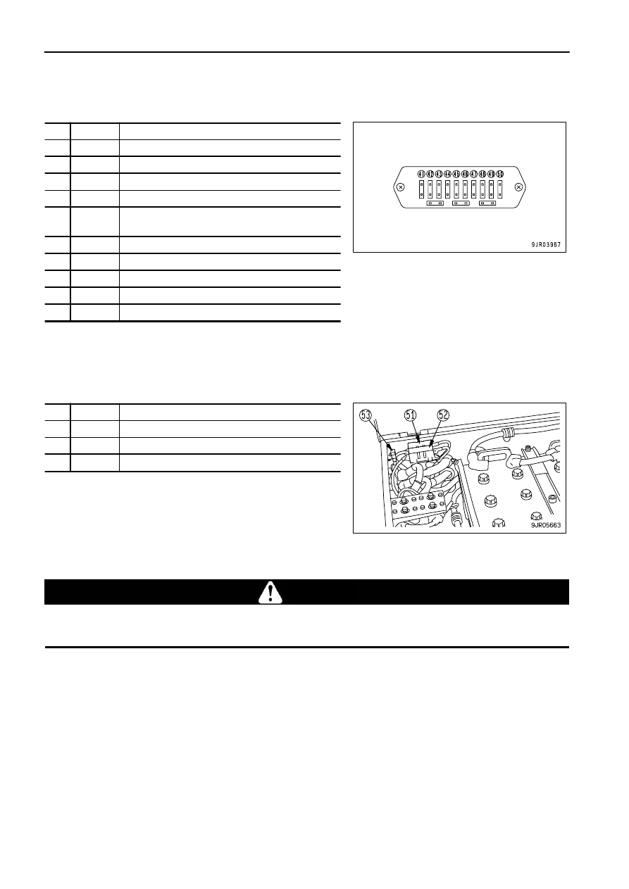
Fuse box BT4

No. Capacity

Name of circuit

(41)

10A

Room lamp

(42)

10A

Power source for engine preheat

(43)

20A

Yellow rotating lamp (if equipped)

(44)

20A

Side lamp (if equipped)

(45)

20A

Air suspension seat (if equipped), 
Electric operator's seat heater (if equipped)

(46)

10A

Payload external display lamp (if equipped)

(47)

10A

Tachograph (if equipped), Cigarette lighter

(48)

20A

Air conditioner

(49)

20A

Spare

(50)

20A

wiper motor

Fuse box V (Inside battery box)

No. Capacity

Name of circuit

(51)

200A

Power source for engine preheat

(52)

200A

Power source for engine preheat

(53)

10A

Power source for emergency steering

Precautions when adding electrical equipment

 CAUTION

If the electrical equipment system is changed, problems may occur in the machine control.  Do not make any changes to the
electrical system.

If you want to make any change to the electrical system, please contact your Komatsu distributor.

3 - 50

OPERATION

EXPLANATION OF COMPONENTS

CAR RADIO

(If equipped)

EXPLANATION OF COMPONENTS

(1)
(2)
(3)
(4)
(5)

Power switch/Volume
Tone control knob
Display
Clock button/Displaying frequency
AST

(6)
(7)
(8)
(9)

Preset switch
Seek
Band selector switch
Tuning switch

POWER SWITCH/VOLUME

When this switch (1) is turned to the right, it clicks and the power is
turned on.  If it is turned further, the speaker volume is adjusted.

3 - 51

OPERATION

EXPLANATION OF COMPONENTS

TONE CONTROL KNOB

If this knob (2) is turned to the right, the high tone is emphasized;
if it is turned to the left, the high tone is reduced.

DISPLAY

This display (3) shows the radio reception frequency and the
operating mode.

CLOCK BUTTON/DISPLAYING FREQUENCY

When this button (4) is pressed, the display changes to the time.
If it is pressed again, it displays the frequency.

AST

When this button (5) is pressed, the preset stations are called up
in turn.
When the desired broadcasting station is reached, press the
button again to stop it.
If the button is kept pressed continuously for 2 seconds, it is set to
auto memory.

3 - 52

OPERATION

EXPLANATION OF COMPONENTS

PRESET SWITCH

With this switch (6), each button can be set to one station each for
FM and MW (AM).   (For details of the method of resetting, see
"METHOD OF PRESET (PAGE 3-55)".)

SEEK

When this switch (7) ("SEEK") is pressed, it automatically
searches for stations that can be received, and when it receives a
station, it stops.

BAND SELECTOR SWITCH

When this switch (8) ("BAND") is pressed, the band is switched
between FM and MW (AM).
The reception band and frequency are displayed on the display.

TUNING SWITCH

When the "TUNE" button

!

 of switch (9) is pressed, the frequency

goes up; when the

"

 button is pressed, the frequency goes down.

If it is kept pressed, the frequency changes continuously.

3 - 53

OPERATION

EXPLANATION OF COMPONENTS

METHOD OF OPERATION

LISTENING TO RADIO

 1. This switches on power (1) for the radio.
 2. "BAND" switch (2) is used to select MW (AM) or FM.
 3. Use the preset switch or tuning switch (3) to select the station.
 4. Adjust the volume and tone as desired.
 5. To turn the radio OFF, turn VOL knob (1) to the left until a click

is heard.

METHOD OF AUTOMATIC TUNING

When the "SEEK" switch is pressed, it moves up to higher
frequencies and when it finds a station that can be received, it
stops automatically.

METHOD OF MANUAL TUNING

When the TUNE button

!

 is pressed, the frequency goes up;

when the

"

 button is pressed, the frequency goes down.  If it is

kept pressed, the frequency changes continuously.

3 - 54

OPERATION

EXPLANATION OF COMPONENTS

METHOD OF PRESET

 1. Select the desired preset station.

Use the "BAND" button to select MW (AM) or FM, and use the
"TUNE" button to select the frequency of the broadcasting
station.

 2. Decide the number of the button to be preset, and keep it

pressed for 2 seconds.   The number of the button will be
displayed and the presetting is completed.

 3. Repeat Steps 1 to 2 to preset other broadcasting stations.

To change the setting of a preset switch to another station,
repeat Steps 1 to 2.
If the battery is replaced or the power is switched off, all the
preset settings are deleted.   Carry out the presetting
operation again.
It is possible to preset 6 AM (MW) stations and 6 FM
stations.

METHOD OF AUTOMATIC MEMORY

If the "AST" button is pressed for 2 seconds, the broadcasting
stations that can be received in the area are called up in turn, and
the broadcasting stations are automatically saved in the preset
memory.

AUTOMATIC SWITCHING RECEPTION OF MONAURAL/STEREO

If the reception of the FM stereo broadcast being received is weak (when you are far from the broadcasting station
or are surrounded by hills), the radio is automatically switched from stereo to monaural to reduce the interference.
When the stereo broadcast becomes stronger, it automatically switches back to stereo broadcasting.

3 - 55

OPERATION

EXPLANATION OF COMPONENTS

ADJUSTING TIME

 1. Turn the radio power ON.  If the display shows the frequency,

set the CLOCK button to the time display.

 2. To set the time, keep the CLOCK button pressed and

Press the

!

 button to change the minutes

Press the

"

 button to change the hours

PRECAUTIONS FOR USE

Stow the antenna when traveling in places with low overhead clearance.
To ensure safety, always keep the sound to a level where it is possible to hear outside sounds during operation.
If water gets into the speaker case or radio, it may lead to an unexpected failure, so be careful not to get water
on the equipment.
Do not wipe the scales or buttons with benzene, thinner, or any other solvent.  Wipe with a soft dry cloth.  Use a
cloth soaked in alcohol if the equipment is extremely dirty.

3 - 56

OPERATION

EXPLANATION OF COMPONENTS

CAR STEREO

(If equipped)

EXPLANATION OF COMPONENTS

(1) Power switch/volume
(2) Auto-store/preset scan button
(3) Bass control knob
(4) Treble control knob
(5) Loudness button
(6) Time/radio display selector button
(7) Tape eject button

(8) Cassette door
(9) Fast forward, rewind buttons
(10) Preset buttons
(11) Metal tape button
(12) Manual tuning buttons
(13) Seek tuning buttons
(14) Band selector button

(A) Band display
(B) Metal tape display
(C) FM stereo reception display
(D) Loudness display

(E) Tape direction display
(F) Preset channel display
(G) Time/frequency display

3 - 57

OPERATION

EXPLANATION OF COMPONENTS

POWER SWITCH/VOLUME

Turn this knob (1) to the right until it clicks to turn the power on.
Turn it further to increase the volume.

AUTO-STORE/PRESET SCAN BUTTON

Use this button (2) to actuate the preset scan and auto-store
functions.

Auto-store
Each time this button is pressed for more than 2 seconds while
in radio reception, this auto-store function automatically starts to
search for the desired station within a receivable band, and
memorize the frequency in the preset memory. During this
scanning process, the frequency shown in the right side of
display continues to change. This indicates that each frequency
is memorized in the auto-store.

REMARK

The auto-store function cannot be used when the channel display
is flashing.
When the display is flashing, the preset scan function is being
used.

Preset scan
If this button is pressed for less than 0.5 second while in radio reception, programs from the six preset stations
in the same band will be broadcast one after another for 5 seconds each, starting from No. 1 through No. 6
stations consecutively.
When the desired station is found, press the button again. This stops the preset scan tuning process and switches
to  ordinary broadcasting. The same process will be repeated continuously until the button is pressed again.

BASS CONTROL KNOB

Turn this button (3) to the left to reduce the low tones; turn it to the
right to emphasize the low tones.
Direction (a): Low tone reduced
Direction (b): Low tone emphasized

3 - 58

OPERATION

EXPLANATION OF COMPONENTS

TREBLE CONTROL KNOB

Turn this button (4) to the left to reduce the low tones; turn it to the
right to emphasize the high tones.
Direction (a): High tone reduced
Direction (b): High tone emphasized

LOUDNESS BUTTON

This button (5) is used when playing at low volume. It makes it
possible to hear more easily by emphasizing the low tone when the
low tones are weak.
Push button: Actuated (ON)
Push button again: Canceled (OFF)

TIME/RADIO DISPLAY SELECTOR BUTTON

This button (6) is used to switch between the "Radio/tape display"
and the "Time display".

Correcting the time
Press the button to set the time display.
(A) Correcting hour:

Keep the DISP button pressed and press the bottom (H) of
the TUNING button to correct the hour.

(B) Correcting minute:

Keep the DISP button pressed and press the top (M) of the
TUNING button to correct the minute.

3 - 59

OPERATION

EXPLANATION OF COMPONENTS

TAPE EJECT BUTTON

This button (7) is used to stop the tape and to eject the cassette.
When this button is pressed, the tape is ejected and the radio
plays.

CASSETTE DOOR

Set the cassette with the exposed portion of the tape on the right
side and insert it through the cassette door (8).

FAST FORWARD, REWIND BUTTONS

These buttons (9) are used to fast-forward or rewind the tape.

Fast-forward/rewind
If you press the button pointing in the same direction as the
lighted arrow indicating the direction of play, the tape will be
fast-forwarded; if you press the button pointing in the opposite
direction, the tape will rewind.
To stop the tape, lightly press the button that is not locked.  The
fast-forward or rewind operation will be canceled.
If the fast forward and rewind buttons are pressed at the same
time, the tape will change sides.

PRESET BUTTONS

These buttons (10) are used to call up the broadcast station
frequencies preset in memory for each of buttons No. 1 to No. 6.
It is possible to preset 18 stations (FM: 12; AM: 6) with these
buttons.

3 - 60

OPERATION

EXPLANATION OF COMPONENTS

METAL TAPE BUTTON

(used also for preset button No. 5)
This button (11) is used when playing a metal or chrome tape. This
button is also used for preset button No. 5. When it is pressed,
"MTL" appears on the display.

MANUAL TUNING BUTTONS

These buttons (12) are used for manual tuning.
When "TUN

" button is pressed, the frequency goes up 9 kHz for

AM or 0.1 MHz for FM; when "TUN

" button is pressed, the

frequency goes down 9 kHz for AM or 0.1 MHz for FM.
If the button is pressed down and held, the frequency will change
continuously.

SEEK TUNING BUTTONS

These buttons (13) are used to seek tuning.
When the "SEEK UP" button is pressed, the search automatically
goes up; when the "SEEK DOWN" button is pressed, the search
automatically goes down.
When the next station that can be received is found, it
automatically stops.

BAND SELECTOR BUTTON

When this button (14) is pressed, the band is switched between
FM1, FM2, and MW (AM).  The band is shown on the display.

3 - 61

OPERATION

EXPLANATION OF COMPONENTS

METHOD OF OPERATION

METHOD OF SETTING PRESET BUTTONS

To listen to a preset station, use band selector button (1) to select
AM, FM1, or FM2, then press the preset switch number to listen to
the desired station.
It is possible to preset six AM stations and 12 FM stations (FM1: 6,
FM2: 6).

 1. If you are playing a cassette, press the tape eject button to stop

the tape.

 2. Select the station to be preset.

Use band selector button (1) to select MW (AM), FM1, or FM2,
then use the manual tuning button to select the frequency of
the broadcasting station.

 3. Press manual memory button (2) or seek tuning button (3).
 4. Press preset button (4) of the number to be preset for 2

seconds while the frequency display is being shown on the
display. (The preset channel and frequency are displayed and
the presetting is completed).

 5. Repeat Steps 2 to 4 to preset other stations.

REMARK

Use Steps 2 to 4 also when changing the setting of a preset
switch to another station.
When the power is disconnected, such as when the battery is
replaced, all the settings are deleted, so preset the stations
again.

3 - 62

OPERATION

EXPLANATION OF COMPONENTS

MANUAL MEMORY BUTTON

Select the station to be preset with manual tuning button (1) or
seek tuning button (2), then keep button No.1 to button No.6 of
button (3) pressed for 2 seconds while the frequency is being
displayed to preset the station.

LISTENING TO RADIO

 1. Turn the starting switch ON, then turn power switch (1) ON.
 2. Set band selector button (2) to AM or FM.
 3. Select the station with the preset buttons or manual tuning

button (3).

 4. Adjust the volume, balance, and tone as desired.
 5. When turning the radio OFF, turn power switch (1) to the left

until it clicks.

REMARK

To switch to the radio when listening to a cassette, press the cassette eject button to stop the tape.
If you insert a cassette when listening to the radio, the tape will start to play.

3 - 63

OPERATION

EXPLANATION OF COMPONENTS

LISTENING TO CASSETTE TAPE

 1. Turn the starting switch ON, then turn power switch (1) ON.
 2. Set the cassette with the exposed portion of the tape on the

right side and push it past the cassette door. The tape will
automatically start playing.
If the arrow indicating the direction of play is pointing to the
right, the top side is being played; if the arrow is pointing to the
left, the bottom side is being played.
When the tape reaches the end, it is automatically reversed
and the other side starts to play.

 3. When finished with the tape, press the cassette eject button to

eject the tape and automatically switch to the radio.

REVERSING TAPE

When listening to the tape, press both FAST FORWARD,
REWIND buttons (A) and (B) at the same time lightly.
When this is done, the tape direction display will be reversed.

3 - 64

OPERATION

EXPLANATION OF COMPONENTS

PRECAUTIONS FOR USE

Stow the antenna when traveling in places with low overhead clearance.
To ensure safety during operations, keep the volume at a level where it is possible to hear other machines.
If water gets inside the speaker case or radio (auto tuning), it may cause a serious problem, take care not to let
water get in these items.
Do not wipe the scales or buttons with benzene, thinner, or any other solvent.  Wipe with a soft dry cloth.  Use a
cloth soaked in alcohol if the equipment is extremely dirty.

NOTICE
Handling cassette tape

Clean the tape head approx. once a month with a commercially available head cleaning tape.
Do not leave the tape any place where it is exposed to direct sunlight, any place that is excessively dusty, or any place where
there is a magnetic field.
Do not use 120-minute tapes.  The tape is thin and it easily gets caught up inside the machine.
If the tape is slack, it easily gets caught up inside the machine.  Use a pencil to wind in the tape to remove any slack.
Do not use any cassette tape if the label has started to come off.  It may cause defective rotation, or it may be impossible to get
the tape out of the machine.

3 - 65

OPERATION

EXPLANATION OF COMPONENTS

AIR CONDITIONER

(If equipped)
By taking fresh air into the cab through a filter, it is possible to raise the pressure inside the cab. This makes it
possible to provide a pleasant working environment even on dusty jobsites.

GENERAL LOCATIONS ON CONTROL PANEL

(1)
(2)
(3)
(4)

ON/OFF switch
Fan switch
Air conditioner switch
Mode selector switch

(5)
(6)
(7)

DEF switch
RECIRC/FRESH selector switch
Temperature control switch

Air conditioner monitor

(A)
(B)

Air flow bar
Air conditioner operation symbol

(C)
(D)

RECIRC/FRESH selector symbol
Temperature bar

ON/OFF SWITCH

Use this switch (1) to turn the air conditioner ON/OFF.
When the switch is turned ON, the air conditioner monitor displays the setting being used when the switch was
previously turned OFF.

FAN SWITCH

With this switch (2) it is possible to adjust the air flow from the fan to 4 levels.
Press the

 switch to increase the air flow; press the

 switch to reduce the air flow.

The air flow is shown in air flow bar (A) on the air conditioner monitor.

3 - 66

OPERATION

EXPLANATION OF COMPONENTS

AIR CONDITIONER SWITCH

Use this switch (3) to actuate the cooling, heating, or dehumidifying functions, or to stop the air conditioner.
When the switch is pressed, air conditioner operation symbol (B) is displayed on the air conditioner monitor.  When
the switch is pressed again, the air conditioner is switched OFF and the operation symbol goes out.

MODE SELECTOR SWITCH

Use this switch (4) to select the vents.
There are three combinations of vents: FACE, FACE/FOOT, and
FOOT.
Each time the switch is pressed, the vent display on the air
conditioner monitor changes in the order FACE, FACE/FOOT,
FOOT, FACE.

REMARK

Air also blows out from the defroster vent in FOOT mode.

DEF SWITCH

Use this switch (5) to change the vents to the DEF mode.
When the switch is pressed, the vent display on the air conditioner
monitor changes as shown in the diagram on the right.

When the DEF switch is pressed in any of the FACE, FACE/FOOT,
or FOOT modes, the system changes to the DEF mode.   In
addition, when the DEF mode is being used, if the mode selector
switch is pressed, it will return to the mode being used before
switching to the DEF mode.

REMARK

Air also blows out from the foot vent in DEF mode.

3 - 67

OPERATION

EXPLANATION OF COMPONENTS

RECIRC/FRESH SELECTOR SWITCH

Use this switch (6) to switch between recirculation of the internal air
(RECIRC) or intake of external air (FRESH).  When the switch is
pressed, the display of RECIRC/FRESH selector symbol (C) on
the air conditioner monitor changes.
(It changes in the order RECIRC, FRESH, RECIRC.)

RECIRC: Only the air inside the cab is circulated.  Use this position

when it is needed to carry out quick heating or cooling of
the cab, or when the outside air is dirty (smells or is
dusty).

FRESH: Fresh air is taken in from the outside for normal heating or

cooling of the cab.  Use this position to make the air inside
the cab fresh or to remove the mist from the cab windows.
When the air conditioner takes in fresh air from the
outside, the pressure inside the cab rises and this
prevents the entry of dirt.  The higher the position of the
fan switch, the more efficient this becomes.

TEMPERATURE CONTROL SWITCH

Use this switch (7) to adjust the temperature of the air blowing out from the vents.  The adjustment can be made to
8 levels from low temperature to high temperature.
The temperature of the air blowing out from the vents is displayed on temperature bar (D) on the monitor.  The lower
the number of segments lighted up on the bar, the lower the temperature is.

Press the > switch to raise the temperature; press the < switch to lower the temperature.

Even when the starting switch is turned OFF, the settings of each mode are retained in memory.  However, in the
following cases, the settings must be made again.

When the machine has not been used for more than seven days
When the battery voltage is extremely low
When there is abnormal interference from the surrounding area
When the fan switch has been turned OFF (only the air conditioner switch setting is retained)

3 - 68

OPERATION

EXPLANATION OF COMPONENTS

METHOD OF OPERATION

With the FACE vents, it is possible to adjust the direction of the air flow and to turn it on or off.
However, do not set to the FACE mode with the vents closed.

COOLING

 1. Press ON/OFF switch (1) to turn on the air conditioner power.
 2. Press fan switch (2) to set the air flow to the maximum.
 3. Press temperature control switch (3) to lower the temperature.
 4. Press air conditioner switch (4) to set to COOLING.
 5. Press RECIRC/FRESH selector switch (5) to set to RECIRC.
 6. Press mode selector switch (6) to set the vents to FACE.
 7. When the temperature inside the cab goes down, set to the

desired temperature and air flow.

NOTICE
If operations are continued for a long time with the air conditioner set to the lowest temperature and minimum air flow, there is
danger that the receiver drier may freeze.
If it freezes and no cold air comes out, stop using the cooling, and set to a higher temperature and the maximum air flow.  Run for
a short time under these conditions, then return to the cooling operation.

HEATING

 1. Press ON/OFF switch (1) to turn on the air conditioner power.
 2. Press fan switch (2) to set the air flow to the maximum.
 3. Press temperature control switch (3) to raise the temperature.
 4. Press RECIRC/FRESH selector switch (4) to set to FRESH.
 5. Press mode selector switch (5) to set the vents to FOOT.
 6. When the temperature inside the cab goes up, set to the

desired temperature and air flow.

REMARK

The heating uses the heat from the engine cooling water, so it is effective only when the cooling water is hot.

3 - 69

OPERATION

EXPLANATION OF COMPONENTS

DEHUMIDIFYING, DEFROSTING

 1. Press ON/OFF switch (1) to turn on the air conditioner power.
 2. Press fan switch (2) to set to the desired air flow.
 3. Press temperature control switch (3) to set to the desired

temperature.

 4. Press RECIRC/FRESH selector switch (4) to set to FRESH.
 5. Press mode selector switch (5) or DEF switch (6) to set the

vents to the desired position.

 6. Press air conditioner switch (7) to operate the cooling.

REMARK

If the ambient temperature is below 0

°

C (32

°

F), the air conditioner cooling may not work.  In this case, set to

RECIRC and warm up the inside of the cab, then turn the air conditioner switch ON to operate the cooling.
When defrosting, if the temperature control switch is pressed to set the temperature bar to the maximum (all 8
segments on the bar light up), this will improve the efficiency of removing the frost and preventing mist.

3 - 70

OPERATION

EXPLANATION OF COMPONENTS

PRECAUTIONS WHEN USING AIR CONDITIONER

To prevent putting any excessive load on the engine or compressor, turn the air conditioner ON only when the
engine is running.

Carry out ventilation from time to time when using the cooling.

When turning the cooling on, if the temperature inside the cab is high, open the doors and windows to bring in
fresh air before starting the air conditioner.
If you smoke when using the cooling, your eyes may sting.  If this happens, switch temporarily to cooling and
ventilation to remove the smoke.
When using the air conditioner for a long time, carry out ventilation and cooling once every hour.

Be careful not to cool the cab too much.

For reasons of health, the optimum setting for cooling is considered to be when it feels slightly cool (5 or 6

°

C (9 or

10.8

°

F) lower than the ambient temperature) when you enter the cab.  Do not make the temperature inside the cab

too low or direct the air flow directly onto your skin.
Be extremely careful to select the appropriate temperature.

When cooling is not being used (off-season)

To prevent leakage of the refrigerant from the air conditioner cooling circuit, operate the air conditioner for several
minutes 2 or 3 times a month during the off-season.  If the air conditioner is left for a long time when the refrigerant
is leaking, it may cause internal rust.

INSPECTION AND MAINTENANCE

Even when not using the air conditioner, run the compressor at low speed for several minutes once a week to
prevent the loss of the oil film at various parts of the compressor.   (Run the engine at low speed and set the
temperature control lever to  the central position.)

When cleaning the air conditioner air filter or checking the refrigerant level, see  "CLEAN AIR CONDITIONER AIR
FILTER (PAGE 4-35)" and "CHECK REFRIGERANT (GAS) LEVEL (PAGE 4-36)" for details.

To enable the air conditioner to perform to the full and to maintain a pleasant working environment, always contact
your Komatsu distributor to have the air conditioner refilled with refrigerant and to carry out other checks.

3 - 71

OPERATION

EXPLANATION OF COMPONENTS

HANDLING MACHINES EQUIPPED WITH VHMS

VHMS is a machine management system.  When a communications terminal is installed, it is possible to transmit
data.
A contract is necessary before the VHMS communications terminal can be used.  Any customers desiring to use
the VHMS system should consult their Komatsu distributor.

VHMS INSTALLED, COMMUNICATIONS TERMINAL NOT INSTALLED

BASIC PRECAUTIONS

 WARNING

Never disassemble, repair, modify, or move the VHMS or cables.  This may cause failure or fire on the VHMS equipment or the
machine itself.  (Your Komatsu distributor will carry out removal and installation of VHMS.)
Do not allow cables or cords to become caught; do not damage or pull cables or cords by force.  Short circuits or disconnected
wires may cause failure or fire on the VHMS equipment or the machine itself.

REMARK

There is absolutely no need to inspect or operate the VHMS, but if any abnormality is found, please contact your
Komatsu distributor.

VHMS AND COMMUNICATIONS TERMINAL INSTALLED

The VHMS equipment is a wireless device using radio waves, so it is necessary to obtain authorization and
conform to the laws of the country or territory where the machine equipped with VHMS is being used.  Always
contact your Komatsu distributor before selling or exporting any machine equipped with VHMS.
When selling or exporting the machine or at other times when your Komatsu distributor considers it necessary,
it may be necessary for your Komatsu distributor to remove the VHMS equipment or to carry out action to stop
communications.

If you do not obey the above precautions, neither Komatsu nor your Komatsu distributor can take any
responsibility for any problem that is caused or for any loss that results.

BASIC PRECAUTIONS

 WARNING

Never disassemble, repair, modify, or move the VHMS, terminal, antenna, or cables.  This may cause failure or fire on the VHMS
equipment or the machine itself.  (Your Komatsu distributor will carry out removal and installation of the VHMS and terminal.)
Do not allow cables or cords to become caught; do not damage or pull cables or cords by force.  Short circuits or disconnected
wires may cause failure or fire on the VHMS equipment or the machine itself.
For anyone wearing a pacemaker, make sure that the communications antenna is at least 22 cm from the pacemaker.  The radio
waves may have an adverse effect on the operation of the pacemaker.

NOTICE

Please contact your Komatsu distributor before installing a top guard or other attachment that covers the antenna.
Be careful not to get water on the communications terminal or wiring.

3 - 72

OPERATION

EXPLANATION OF COMPONENTS

REMARK

The communications terminal uses wireless communications, so it cannot be used inside tunnels, underground,
inside buildings, or in mountain areas where radio waves cannot be received.  Even when the machine is outside,
it cannot be used in areas where the radio signal is weak or in areas outside the wireless communication service
area.
There is absolutely no need to inspect or operate the VHMS or communications terminal, but if any abnormality
is found, please contact your Komatsu distributor.

PROCEDURE WHEN DOWNLOADING

WHEN DOENLOADING FROM CONNECTOR INSIDE CAB (BEHIND ASSISTANT'S SEAT)

 1. Turn the starting switch to the ON position.
 2. When downloading, remove download connector (1) and

download.

WHEN DOENLOADING FROM GROUND LEVEL DOENLOAD BOX OUTSIDE CAB

 1. Turn the starting switch to the OFF position.
 2. Use the starting switch to open the box.
 3. Set switch (2) inside the box to the ON position.

When display lamp (3) lights up, the system is ready to
download.
Start the download.

 4. Close the box and lock it with the key.

3 - 73

OPERATION

OPERATION

OPERATION

CHECK BEFORE STARTING ENGINE

WALK-AROUND CHECK

Before starting the engine, look around the machine and under the machine to check for loose nuts or bolts, or
leakage of oil, fuel, or coolant, and check the condition of the hydraulic system.
Check also for loose wiring, play, and accumulation of dust in places that get very hot and are exposed to extremely
high temperatures.

 WARNING

Always hang the warning tag from the shift lever.
Leakage  of oil or fuel, or accumulation of flammable material around the battery or high temperature parts of the engine, such
as the engine muffler or turbocharger, may cause fire.  Check carefully, and if any problem is found, repair it or contact your
Komatsu distributor.

Always carry out the following items before starting the engine each day.

 1. Check the dump body, frame, tires, cylinders, linkage, and hoses for cracks or excessive wear or play.

Check the dump body, frame, tires, cylinders, linkage, and hoses for cracks or excessive wear or play, and carry
out repairs if any problem is found.

 2. Remove dirt from around engine, battery, radiator, and aftercooler.

Check that there is no dirt or dust accumulated around the engine, radiator or aftercooler. Check also that there
is no flammable material (dry leaves, twigs, etc.) accumulated around the battery, or engine, muffler,
turbocharger, or other high temperature parts of the engine. Remove any dirt or flammable materials that are
found.

 3. Check for leakage of water or oil around engine

Check that there is no oil leakage from the engine or coolant leakage from the cooling system. If any problem
is found, repair it.

 4. Check for oil leakage from transmission case, differential case, final drive case, steering/hoist oil tank, hoses,

and joints
Check that there is no oil leakage. If any problem is found, repair the place where the oil is leaking.
Check for leakage of oil from the undercover. Check the ground for traces of oil leakage.

 5. Check for loose air cleaner mounting bolts.

Check for the loose bolts. If loose, tighten them.

 6. Check dump body mount rubber

Check for any cracks, embedded foreign objects, or loose bolts.

 7. Check for damage to handrail, loose bolts

Repair any damage and tighten any loose bolts.

3 - 74

OPERATION

OPERATION

 8. Check for damage to gauges, lamps on the instrument panel and loose bolts.

Check for damage to the panel, gauges and lamps. If any problem is found, replace the parts. Clean off any dirt
on the surface. Tighten any loose bolts.

 9. Check rear view mirror, under view mirror

Check for any damage to the mirrors, and if any damage is found, replace the mirror. Clean all dirt from the
surface of the mirror and adjust the angle so that the view to the rear and below the machine can be seen from
the operator's seat.

10. Check for damage to the seat belt and mounting clamps.

Check that there is no problem in the seat belt or mounting clamps. If there is any damage, replace with new
parts.

Check for any loose bolts of the clamps mounting the equipment to the machine. Tighten any loose bolts.
When the belt has been used for a long time, if any external damage or fraying of the belt can be seen, or if
the clamps are broken or deformed, replace the seat belt.

11. Inspect tires.

 WARNING

If worn or damaged tires are used, they may burst and cause serious injury
or death.
To ensure safety, do not use the following tires.
Wear:

Tires with a tread grooves of less than 15% of that of a new tire
Tires with extreme uneven wear or with stepped-type wear

Damage:

Tires with damage that has reached the cords, or with cracks in the
rubber
Tires with cut or pulled cords
Tires with peeled (separated) surface
Tires with damaged bead
Leaking or improperly repaired tubeless tires
Deteriorated, deformed or abnormally damaged tires, which do not
seem usable

12. Inspect rims.

 WARNING

Check the rims (wheels) and rings for deformation, corrosion and cracks.
In particular, check the side rings, lock rings and rim flanges thoroughly.

3 - 75

OPERATION

OPERATION

CHECK BEFORE STARTING

Always perform the procedures in this section before starting the engine each day.

CHECK COOLANT LEVEL, ADD COOLANT

 WARNING

Do not open the radiator cap unless necessary.  When checking the coolant, always wait for the engine to cool down and check
the sub tank.
Immediately after the engine is stopped, the coolant is at a high temperature and the radiator is under high internal pressure.
If the cap is removed to check the coolant level in this condition, there is  a hazard of burns.  Wait for the temperature to go
down, then turn the cap slowly to release the pressure and remove it carefully.

 1. Check that the cooling water in sub tank (1) is between the

FULL and LOW marks.

 2. If the level is LOW, remove cap (2) and add the engine coolant

up to the FULL mark.

 3. If there is no coolant in the subtank, add water to the radiator

through water filler (3) at the top of the radiator, then add water
to the subtank.

 4. Check that there is no oil in the engine coolant or any other

problem.

 5. After adding coolant, tighten the cap securely.
 6. If more coolant is added than normal, then check for water

leakage.

3 - 76

OPERATION

OPERATION

CHECK DUST INDICATOR

 1. Check that the yellow display in the transparent portion of dust

indicator (1) does not indicate 7.5 kPa (0.076 kgf/cm

2

, 1.1 PSI).

 2. If the red line indicates 7.5 kPa (0.076 kgf/cm

2

, 1.1 PSI), clean

or replace the air cleaner element immediately.
For details of the method of cleaning the element, see
"CHECK, CLEAN OR REPLACE AIR CLEANER (PAGE
4-26)".

 3. After checking, cleaning, or replacing, press the top of dust

indicator (1) to return the yellow display to its original position.

3 - 77

OPERATION

OPERATION

CHECK OIL LEVEL IN ENGINE OIL PAN, ADD OIL

 WARNING

Parts and oil are at high temperature immediately after the engine is stopped and may cause serious burns. Wait for the oil
temperature to go down before performing this operation.

 1. Check the oil level with dipstick (G).
 2. Take out the dipstick (G) and wipe off the oil with cloth.
 3. Fully insert dipstick (G) into filler pipe (F), then remove it.

When inserting, insert so that the oil level gauge indicator is
facing the engine.

 4. The oil level should be between the H and L marks on the

ENGINE STOPPED side of dipstick (G).
If the oil is below the L mark, add oil through oil filler (F).

 5. If the oil is above the H mark, remove drain plug (1), and loosen

drain valve (2) to drain the excess engine oil, then check the
engine oil level again.

 6. If the oil level is correct, tighten the handle of the oil filler cap

securely.

REMARK

When checking the oil level after the engine has been operated, wait for at least 15 minutes after stopping the
engine.
If the machine is at an angle, make it horizontal before checking.
The dipstick has the oil level marked on both sides: ENGINE STOPPED for measuring when the engine is
stopped, and ENGINE IDLING for measuring when the engine is idle.
When checking the oil level, stop the engine and check with the ENGINE STOPPED side of the dipstick.
It is also possible to check when the engine is idle, but the following procedure must be used.

 Check that the engine water temperature is in the white range.

 Use the ENGINE IDLING side of the dipstick.

 Remove the oil filler cap.

3 - 78

OPERATION

OPERATION

CHECK OIL LEVEL IN TRANSMISSION CASE, ADD OIL

 1. After starting the engine, run the engine at low idle and check

the oil level with sight gauge (G2).

 2. If the oil level is low, add oil through oil filler (F).

NOTICE

The oil level changes according to the oil temperature, so carry out the
check after completing the warming-up operation.
During operations, or when the engine is running at idle after
operations, the oil level should be above (G2).
When checking the oil level with the engine stopped, check with sight
gauge (G1) as a guide line, and make the final check with (G2).
When checking the oil level with the engine stopped, wait for 20 minutes
after stopping the engine and check with sight gauge (G1).

CHECK OIL LEVEL IN STEERING AND HOIST OIL TANK, ADD OIL

 WARNING

When removing the oil filler cap, oil may spurt out, so turn the cap slowly to release the internal pressure before removing the cap.

 1. Check with sight gauge (G).
 2. If the oil level is not up to the window of sight gauge (G), add oil

through oil filler (F).

3 - 79

OPERATION

OPERATION

CHECK OIL LEVEL IN BRAKE SUB-TANK, ADD OIL

 WARNING

Immediately after the machine is stopped, the pressure inside the tank is high, so if the cap is opened, hot oil will spurt out and
may cause burns. Turn the cap slowly to release the pressure inside the tank before opening the oil filler cap.

 1. Check with sight gauge (H). If it is possible to check the level

with the sight gauge, the level is correct.

 2. If the oil level is not up to the top of gauge (H), add oil through

oil filler port (F).

REMARK

When the engine starts, the oil level in the sight gauge may go
down temporarily, but this does not indicate any abnormality.

3 - 80

OPERATION

OPERATION

CHECK FOR LEAKAGE OF OIL FROM BRAKE OIL RECOVERY TANK

 1. Check that there is no oil leaking from overflow tube (1) of the brake oil recovery tank.
 2. If any oil is leaking, recover the oil. For details, see "RECOVER OIL LEAKING FROM FLOATING SEAL (PAGE

4-82)".

Front

Rear

DRAIN WATER, SEDIMENT FROM FUEL TANK

Loosen valve (1) at the bottom of the fuel tank, and drain the water
and sediment collected at the bottom of the tank together with the
fuel.

3 - 81


Content      ..     2      3      4      5     ..