Galeo HD785-7 DUMP TRUCK. Operation and Maintenance Manual (2006) - page 8
 

  Index      Manuals     Galeo HD785-7 DUMP TRUCK. Operation and Maintenance Manual (2006)


Search            copyright infringement  


Content      ..     6      7      8      9     ..


Galeo HD785-7 DUMP TRUCK. Operation and Maintenance Manual (2006) - page 8


MAINTENANCE

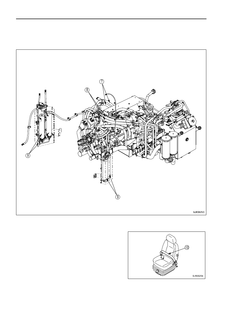
PERIODIC REPLACEMENT OF SAFETY CRITICAL PARTS

Hose at discharge side of brake cooling pump (7)
Hose at discharge side of transmission pump (8)
Accumulator (9)

Seat belt (10)

4 - 22

MAINTENANCE

MAINTENANCE SCHEDULE CHART

MAINTENANCE SCHEDULE CHART

MAINTENANCE SCHEDULE CHART

INITIAL 250 HOURS SERVICE (ONLY AFTER THE FIRST 250 HOURS)

Replace transmission oil filter element

4- 69

Change oil in transmission, brake cooling oil tank, wash strainer

4- 74

Replace transmission, brake cooling oil filter element

4- 77

Replace steering, hoist oil tank filter element

4- 84

Change oil in final drive case

4- 84

Change oil in differential case

4- 85

Change oil in steering, hoist oil tank

4- 87

WHEN REQUIRED

Check, clean or replace air cleaner

4- 26

Clean inside of cooling system

4- 32

Check level of window washer fluid, add fluid

4- 35

Clean air conditioner air filter

4- 35

Check refrigerant (gas) level

4- 36

Check dump body

4- 36

Check length of suspension cylinder, check oil level

4- 37

Bleed air from rear brake

4- 38

Bleed air from front brake

4- 39

Bleed air from rear parking brake

4- 40

Bleed air from front parking brake

4- 41

Check play of output coupling of output shaft

4- 41

Check water separator, wash inside of filter case

4- 42

BLEEDING AIR FROM FUEL CIRCUIT

4- 43

Clean, check radiator fins and after cooler fins

4- 46

Cleaning hydraulic tank strainer

4- 47

Replace fan belt, adjust auto tensioner

4- 48

Selection and inspection of tires

4- 50

CHECK BEFORE STARTING

EVERY 250 HOURS SERVICE

Check oil level in differential case, add oil

4- 53

Check oil level in final drive case, add oil

4- 53

Lubrication

4- 54

Check drive shaft

4- 55

Check level of battery electrolyte

4- 56

Check alternator belt tension, adjust

4- 58

Check air conditioner compressor belt tension, adjust

4- 59

Clean breathers

4- 60

Check frame

4- 61

Check braking capacity of foot brake

4- 61

Check braking capacity of retarder brake

4- 62

Check braking capacity of parking brake

4- 63

Check, clean automatic suspension

4- 64

Check of accumulator gas pressure

4- 65

4 - 23

MAINTENANCE

MAINTENANCE SCHEDULE CHART

EVERY 500 HOURS SERVICE

Change oil in engine oil pan, replace engine oil filter cartridge

4- 66

Replace fuel prefilter cartridge

4- 67

Replace transmission oil filter element

4- 69

EVERY 1000 HOURS SERVICE

Replace corrosion resistor cartridge

4- 70

Replace fuel main filter cartridge

4- 71

Change oil in transmission, brake cooling oil tank, wash strainer

4- 74

Change oil in brake sub-tank

4- 76

Replace transmission, brake cooling oil filter element

4- 77

Replace brake oil filter element

4- 78

Lubrication

4- 79

Check wear of rear brake disc

4- 80

Check wear of front brake disc

4- 81

Recover oil leaking from floating seal

4- 82

Check of engine air intake piping clamps for looseness

4- 83

EVERY 2000 HOURS SERVICE

Replace steering, hoist oil tank filter element

4- 84

Change oil in final drive case

4- 84

Change oil in differential case

4- 85

Clean differential case breather

4- 85

Check alternator

4- 86

Check, adjust engine valve clearance

4- 86

Check accumulator gas pressure

4- 86

EVERY 4000 HOURS SERVICE

Change oil in steering, hoist oil tank

4- 87

Lubricate drive shaft

4- 87

Check vibration damper

4- 88

Check starting motor

4- 88

Check water pump

4- 88

Check fan pulley and tension pulley

4- 88

Checking for looseness of high-pressure clamp, hardening of rubber

4- 89

Checking for missing fuel spray prevention cap, hardening of rubber

4- 90

EVERY 8000 HOURS SERVICE

Replace high-pressure piping clamp

4- 91

Replace fuel spray prevention cap

4- 91

Overhaul starting motor and alternator

4- 91

EVERY 15000 HOURS SERVICE

CHECK, REPLACE STEERING A ARM MOUNTING BOLT

4- 92

4 - 24

MAINTENANCE

SERVICE PROCEDURE

SERVICE PROCEDURE

INITIAL 250 HOURS SERVICE (ONLY AFTER THE FIRST 250 HOURS)

Perform the following maintenance only after the first 250 hours.

Replace transmission oil filter element
Change oil in transmission, brake cooling oil tank, wash strainer
Replace transmission, brake cooling oil filter element
Replace steering, hoist oil tank filter element
Change oil in final drive case
Change oil in differential case
Change oil in steering, hoist oil tank

For details of the method of replacing or maintaining, see EVERY 500 HOURS, EVERY 1000 HOURS, EVERY
2000 HOURS SERVICE and EVERY 4000 HOURS SERVICE.

4 - 25

MAINTENANCE

SERVICE PROCEDURE

WHEN REQUIRED

CHECK, CLEAN OR REPLACE AIR CLEANER

After the outer element has been cleaned 6 times, or if the air cleaner element has been used for one year, replace
the outer element, inner element, and O-ring.   For details of the procedure for replacement, see "REPLACE
ELEMENT (PAGE 4-30)".
After the outer element has been cleaned, if the maintenance caution lamp lights up and action code E01 and AIR
FILTER are displayed on the character display at the same time immediately after operations start, replace the
element even if the outer element has not been cleaned 6 times or the air cleaner element has not been used for
one year.

CHECKING

NOTICE
Do not replace the element before the dust indicator reaches 7.5 kPa {0.76kgf/cm

2

}. If it is cleaned frequently, the filtering effect

of the air cleaner will drop, and this will reduce the service life of the engine.

 1. Check if the dust indicator (1) displays 7.5 kPa {0.76kgf/cm

2

}.

If it is displaying 7.5 kPa {0.76kgf/cm

2

}, clean the outer

element.

REMARK

Maintenance caution lamp (2) is on the machine monitor.
If the maintenance caution lamp lights up and E01 and AIR FILTER
are displayed on character display (3), the air cleaner is clogged.
If this happens, clean the air cleaner element.

4 - 26

MAINTENANCE

SERVICE PROCEDURE

CLEAN OUTER ELEMENT

 WARNING

Dirt will fly if compressed air is used for cleaning.  If dirt gets into your eyes it may cause blindness, and if you breathe in the
dust it may damage your lungs.  To prevent these problems, always wear safety glasses, dust mask, and other protective
equipment.
When pulling out the air cleaner element, make sure that you are standing on a firm place.  If your footing is not secure when
you carry out the operation, there is danger of falling and suffering injury.

NOTICE
When cleaning the element, clean only the outer element.  Do not clean the inner element.  There is danger that dirt and dust may
get inside the engine when the outer element is being cleaned, and this will damage the engine.

 1. Stop the engine.

 2. Remove 3 hooks (5) of dust cup (4), then remove the dust cup.

 3. Hold outer element (6) with both hands, and move it up and

down and to the left and right while pulling it out.

 4. Hold inner element (7) so that it does not come out, and clean

the inside of the air cleaner body with a dry cloth.

 5. Use a dry cloth or compressed air to clean off the dirt stuck to

dust cup (4) and vacuator valve (8).

 6. Check that there are no cracks in the lip of the vacuator valve

(8).  If any cracks are found, replace with a new part.

NOTICE

If a damaged element is used, dust will pass the air cleaner filter and be sucked into the engine.  Do not use any cleaning
method that will damage the element.  If the element is damaged, replace it with a new element.
Never tap or hit the element against any other object when cleaning it.
Do not use an element with damaged folds or a damaged gasket or seal.

4 - 27

MAINTENANCE

SERVICE PROCEDURE

MAINTENANCE

SERVICE PROCEDURE

 7. Blow dry compressed air (0.69 MPa {7 kg/cm

2

}) from the inside

of outer element (6) along the folds.  Next, blow along the folds
from the outside, then blow again from the inside.

 8. After cleaning, shine a light bulb from inside outer element (6)

to check.   If any holes or thin places are found, replace the
outer element.

 9. Install outer element (6) in the air cleaner body.

10. Check that O-ring (9) is fitted to dust cup (4).

Next, set so that vacuator valve (8) of dust cup (4) is at the
bottom, and insert it into the air cleaner body.

11. Clip hooks (5) of dust cup (4) to the protruding parts of the air

cleaner body to lock in position.

4 - 28

MAINTENANCE

SERVICE PROCEDURE

MAINTENANCE

SERVICE PROCEDURE

12. Push the head of dust indicator (1) to cancel the clogging

display.

4 - 29

MAINTENANCE

SERVICE PROCEDURE

REPLACE ELEMENT

 WARNING

When pulling out the air cleaner element, make sure that you are standing on a firm place.  If your footing is not secure when you
carry out the operation, there is danger of falling and suffering injury.

 1. Stop the engine.

 2. Remove 3 hooks (5) of dust cup (4), then remove the dust cup.

 3. Hold outer element (6) with both hands, and move it up and

down and to the left and right while pulling it out.

 4. Hold inner element (7) so that it does not come out, and clean

the inside of the air cleaner body with a dry cloth.

 5. Use a dry cloth or compressed air to clean off the dirt stuck to

dust cup (4) and vacuator valve (8).

 6. Check that there are no cracks in the lip of the vacuator valve

(8).  If any cracks are found, replace with a new part.

 7. Pull out inner element (7) and install a new inner element.

 8. Install outer element (6) in the air cleaner body.

4 - 30

MAINTENANCE

SERVICE PROCEDURE

MAINTENANCE

SERVICE PROCEDURE

 9. Replace O-ring (9) with a new part.

Next, set so that vacuator valve (8) of dust cup (4) is at the
bottom, and insert it into the air cleaner body.

10. Clip hooks (5) of dust cup (4) to the protruding parts of the air

cleaner body to lock in position.

11. Push the head of dust indicator (1) to cancel the clogging

display.

4 - 31

MAINTENANCE

SERVICE PROCEDURE

CLEAN INSIDE OF COOLING SYSTEM

 WARNING

Immediately  after the engine is stopped, the engine coolant is hot and the pressure inside the radiator is high.  Removing the
cap and draining the water under this condition could cause burns.  Allow the engine to cool down, then turn the cap slowly
to release the pressure.
Start the engine and flush the system.  When standing up or leaving the operator's seat, set the shift lever to the N position and
set the parking brake switch to the PARKING position.
For details of starting the engine, see "OPERATIONS, CHECKS BEFORE STARTING (PAGE 3-95)" and "STARTING ENGINE
(PAGE 3-97)" in the OPERATION section of the Operation and Maintenance Manual.
When the undercover is removed, there is danger of touching the fan.
Never go to the front of the machine when the engine is running.

Clean the inside of the cooling system, change the coolant and replace the corrosion resistor according to the table
below.

Antifreeze coolant

Interval of cleaning inside of cooling system

and changeing antifreeze coolant

Replacing corrosion resistor

Komatsu supercoolant

(AF-NAC)

Every two years or every 4000 hours

whichever comes first

unnecessary

Permanent type antifreeze

(All-season type, *)

Every year (autumn) or every 2000 hours

whichever comes first

Every 1000 hours

and when cleaning the inside

of the cooling system

and when changing coolant

*: Permanent type antifreeze shall meet the requirements of ASTM D3306-03.

Stop the machine on level ground when cleaning or changing the coolant.
The coolant has the important function of preventing corrosion as well as preventing freezing.
Even in the areas where freezing is not an issue, the use of antifreeze coolant is essential.
Komatsu machines are supplied with Komatsu Supercoolant (AF-NAC). Komatsu Supercoolant (AF-NAC) has
excellent anticorrosion, antifreeze and cooling properties and can be used continuously for 2 years or 4000 hours.
Komatsu Supercoolant (AF-NAC) is strongly recommended wherever available.
To maintain the anticorrosion properties of Supercoolant (AF-NAC),   always keep the density of Supercoolant
between 30% and 68%.

When deciding the ratio of antifreeze to water, check the lowest temperature in the past, and decide from the mixing
table given below.
It is actually better to estimate and temperature about 10

°

C (18

°

F) lower when deciding the mixing ratio.

The mixing ratio depends on the ambient temperature, but it should always be a minimum of 30% by volume
(antifreeze/total amount of coolant x 100).
The freezing temperature of undiluted antifreeze is -15

°

C (5

°

F).  Do not store undiluted antifreeze at a temperature

of below -15

°

C (5

°

F).

4 - 32

MAINTENANCE

SERVICE PROCEDURE

Mixing rate of water and antifreeze

Min. atmospheric

temperature

°

C

-10

-15

-20

-25

-30

°

F

14

5

-4

-13

-22

Amount of antifreeze

Liters

83.7

97.65

111.6 125.55 139.5

US gal 22.113 25.799 28.484 33.170 36.855

Amount of water

Liters

195.3

181.35 167.4 153.45 139.5

US gal 51.597 47.911 44.226 40.540 36.855

Volume ratio

%

30

35

40

45

50

 WARNING

Antifreeze coolant is flammable, so keep it away from flame.
Antifreeze coolant is toxic.  When removing the drain plug, be careful not to get water containing antifreeze coolant on you.  If it
gets in your eyes, flush your eyes with large amount of fresh water and see a doctor at once.

Use antifreeze and appropriate water for diluting (for details, see "COOLANT AND WATER FOR DILUTION (PAGE
4-6)")
We recommend use of an antifreeze density gauge to control the mixing proportions.
Prepare a container whose capacity is larger than the specified coolant volume to catch drained coolant.
Prepare a hose to supply antifreeze coolant and water.

 1. Stop the engine, then set corrosion resistor valve (1) to the

CLOSE position.

 2. Loosen radiator cap (2) slightly to release the air, then remove

the cap.

4 - 33

MAINTENANCE

SERVICE PROCEDURE

MAINTENANCE

SERVICE PROCEDURE

 3. Set a container to catch the drained coolant under drain valve

(3) in the piping between the radiator and water pump under
the machine and under drain plug (4) in the water pump on the
right side of the machine.
Open drain valve (3) and drain plug (4) and drain the water.

 4. After draining the water, close drain valves (3) and drain plug

(4), and fill with tap water.

 5. When the radiator is full, start the engine, and run it at low idle.

Keep the engine running at low idle for 10 minutes until the
water temperature reaches more than 90

°

C (194

°

F).

 6. Stop the engine, open drain valves (3) and drain plug (4), and

drain the water.  After draining the water, close them.

 7. Replace the corrosion resistor, then set valve (1) to the OPEN

position to open it.
For

replacing

corrosion

resistor,

see

"REPLACE

CORROSION RESISTOR CARTRIDGE (PAGE 4-70)".

 8. Add coolant mixed with antifreeze until it overflows from the

water filler.
Decide the proportions of antifreeze and water according to the
table for the mixing rate of water and antifreeze.

 9. To remove the air contained in the coolant, run the engine at

low idle for 5 minutes, then run for a another 5 minutes at high
idle. (When doing this, leave the water filler cap OFF.)

10. Stop the engine.  About 3 minutes later, supply city water up to

the water filler, then close radiator cap.

11. Open drain valve (5) and drain the water from sub tank (6).
12. Flush the inside of sub tank (6) with tap water, then close drain

valve (5).

13. Add water to sub tank (6) until the coolant level is between the

FULL and LOW marks.

4 - 34

MAINTENANCE

SERVICE PROCEDURE

CHECK LEVEL OF WINDOW WASHER FLUID, ADD FLUID

Carry out this check if there is air in the window washer fluid.
Window washer tank (1) is inside the engine hood.

Check the level of the fluid in window washer tank (1), and if it is
low, fill with automobile window washer fluid.
Be careful not to let dirt or dust get in when adding fluid.

When operating at below freezing point, use fluid with antifreeze.

CLEAN AIR CONDITIONER AIR FILTER

If the air filter at the suction port of the air conditioner unit or the air filter at the fresh air intake port become clogged,
the cooling or heating capacity will drop, so clean the filters once a week.

 1. Open cover (1) at the front face of the cab.
 2. Pull out the air filter (FRESH filter) and clean it with

compressed air.

 3. Open cover (2) at the front right of the operator's seat.
 4. Pull out the air filter (RECIRC filter) at the air intake port of the

air conditioner unit, then blow the dust off with a weak jet of
compressed air or clean it off with a soft brush.

4 - 35

MAINTENANCE

SERVICE PROCEDURE

CHECK REFRIGERANT (GAS) LEVEL

 WARNING

If the refrigerant used in the air conditioner gets into your eyes or on your hands, it may cause loss of sight or frostbite.  Do not
touch the refrigerant.  Never loosen any part of the refrigerant circuit.
Do not bring any flame close to any point where the refrigerant gas is leaking.

If the cooling effect is poor, there is possibly lack of refrigerant
(gas).
In this case, check sight glass (2) of receiver drier (1) on the left
side of the radiator.

Before carrying out inspection, set to the following conditions.

Start the engine and run it at approx. 1,500 rpm.
Turn the air conditioner ON/OFF switch to the ON position.
Set the air flow to the maximum position.
Set the temperature to the lowest position.
Open the doors and windows fully.
Turn the air conditioner switch ON.

If the condition of sight glass (2) is "correct" as shown in the
diagram on the right, the condition is normal.   (After the air
conditioner switch is turned ON, a small number of bubbles will be
seen, but after that, the fluid becomes a transparent, milky white
color.)

If the condition of sight glass (2) is "insufficient" as shown in the
diagram on the right, there is lack of refrigerant, so ask your
Komatsu distributor to charge with refrigerant.   (After the air
conditioner switch is turned ON, bubbles can be seen
continuously.)

CHECK DUMP BODY

Check that there are no cracks in the dump body.

 1. Clean the dump body to make it easier to check.
 2. Check all parts of the dump body for damage.

If any cracks or abnormal wear are found, carry out repairs.
Contact your Komatsu distributor for details of the repair procedure.

4 - 36

MAINTENANCE

SERVICE PROCEDURE

CHECK LENGTH OF SUSPENSION CYLINDER, CHECK OIL LEVEL

When traveling, if the unevenness of the road surface is transmitted directly to the chassis (the machine bounces
or the cylinders retract and hit the stopper), carry out the following checks.

CHECK LENGTH OF CYLINDER

Front

Check that the bottom of the suspension cylinder cover is within
range (A) shown by the arrow on the label when the machine is
unloaded and on flat ground.

At the same time, when the machine is not loaded, remove cover (1), then measure dimension (B) from the shoulder
of the rod head of the suspension cylinder to the top surface of the flange.

(B)

237 to 257 mm {9.3 to 10.1 in}

Reference (C)

562 to 582 mm {22.1 to 22.9 in}

After checking, contact your Komatsu distributor for repairs if any problem is found.

Rear

Measure dimension (E) from the shoulder of the rod head of the suspension cylinder to the top surface of the flange.

(E)

189 to 209 mm {7.4 to 8.2}

After checking, contact your Komatsu distributor for repairs if any problem is found.

4 - 37

MAINTENANCE

SERVICE PROCEDURE

BLEED AIR FROM REAR BRAKE

 WARNING

Stop the machine on level ground and put blocks under the wheels before bleeding the air.

To make it easier to bleed the air, warm the oil up to a temperature of at least 40

°

C (104

°

F) before bleeding the air.

Bleed the air from the rear brakes in the same way on both the left and right sides.

 1. Start the engine, check that the oil in the brake sub tank is the specified level, and check if the brake oil pressure

caution lamp is out.

 2. Remove the cap installed to bleeder screw (1) of the slack

adjuster, then insert a vinyl hose.
Prepare a container with oil in it and insert the other end of the
hose approx. 50 mm (2.0 in) below the surface of the oil.
(Use any commercially available vinyl hose.)

 3. Depress the brake pedal and loosen bleeder screw (1) approx.

3/4 turns.   Keep the pedal depressed until no more bubbles
come out from the vinyl hose.

 4. Pull the retarder control lever and loosen bleeder screw (1)

approx. 3/4 turns.  Keep the retarder control lever depressed
until no more bubbles come out from the vinyl hose.

 5. After bleeding the air, tighten bleeder screw (1) securely and fit the cap.
 6. The procedure for bleeder screw (2) of the rear brake is the

same as for the slack adjuster (with Step 4 excluded).

 7. Add oil. For details, see "CHECK OIL LEVEL IN BRAKE

SUB-TANK, ADD OIL (PAGE 3-80)".

4 - 38

MAINTENANCE

SERVICE PROCEDURE

BLEED AIR FROM FRONT BRAKE

 WARNING

Stop the machine on level ground and put blocks under the wheels before bleeding the air.

To make it easier to bleed the air, warm the oil up to a temperature of at least 40

°

C (104

°

F) before bleeding the air.

Repeat the same procedure on the left and right sides.
When bleeding the air from the front brakes and rear brakes at the same time, bleed the air from the rear brakes first.

 1. Start the engine, check that the oil in the brake sub tank is the specified level, and check if the brake oil pressure

caution lamp is out.

 2. Remove the cap installed to bleeder screw (1) of the slack

adjuster, then insert a vinyl hose.
Prepare a container with oil in it and insert the other end of the
hose approx. 50 mm (2.0 in) below the surface of the oil.
(Use any commercially available vinyl hose.)

 3. Depress the brake pedal and loosen bleeder screw (1) approx.

3/4 turns.   Keep the pedal depressed until no more bubbles
come out from the vinyl hose.

 4. Pull the retarder control lever and loosen bleeder screw (1)

approx. 3/4 turns.  Keep the retarder control lever depressed
until no more bubbles come out from the vinyl hose.

 5. After bleeding the air, tighten bleeder screw (1) securely and fit the cap.
 6. The procedure for bleeder screw (2) of the front brake is the same as for the slack adjuster (with Step 4

excluded).

 7. Add oil. For details, see "CHECK OIL LEVEL IN BRAKE SUB-TANK, ADD OIL (PAGE 3-80)".

4 - 39

MAINTENANCE

SERVICE PROCEDURE

BLEED AIR FROM REAR PARKING BRAKE

 WARNING

Stop the machine on level ground and put blocks under the wheels before bleeding the air.

To make it easier to bleed the air, warm the oil up to a temperature of at least 40

°

C (104

°

F) before bleeding the air.

Bleed the air from the parking brakes in the same way on both the left and right sides.

 1. Start the engine, check that the oil in the brake sub tank is the specified level, and check if the brake oil pressure

caution lamp is out.

 2. Remove the cap of bleeder screw (1), install to the block at the

top of the slack adjuster, then insert a vinyl hose.  
Prepare a container with oil in it and insert the other end of the
hose approx. 50 mm (2.0 in) into the oil.   (Use any
commercially available vinyl hose.)

 3. Pull the retarder control lever, set the parking brake switch to

TRAVEL, then loosen bleeder screw (1) approx. 3/4 turns.
Continue until no more bubbles come out from the vinyl hose.

 4. After bleeding the air, tighten bleeder screw (1) securely and fit

the cap.

 5. Bleed the air in the same way from bleeder screw (2) of the rear

parking brake at the block at the top of the slack adjuster.

 6. Add oil. For details, see "CHECK OIL LEVEL IN BRAKE

SUB-TANK, ADD OIL (PAGE 3-80)".

4 - 40

MAINTENANCE

SERVICE PROCEDURE

BLEED AIR FROM FRONT PARKING BRAKE

 WARNING

Stop the machine on level ground and put blocks under the wheels before bleeding the air.

To make it easier to bleed the air, warm the oil up to a temperature of at least 40

°

C (104

°

F) before bleeding the air.

Bleed the air from the parking brakes in the same way on both the left and right sides.

 1. Start the engine, check that the oil in the brake sub tank is the specified level, and check if the brake oil pressure

caution lamp is out.

 2. Remove the cap of bleeder screw (1) of the front parking brake,

then insert a vinyl hose.
Prepare a container with oil and put the other end of the hose
approx. 50 mm (2.0 in) into the oil.
(Use a commercially available vinyl hose.)

 3. Pull the retarder control lever, set the parking brake switch to

TRAVEL, then loosen bleeder screw (1) approx. 3/4 turns.
Continue until no more bubbles come out from the vinyl hose.

 4. After bleeding the air, tighten bleeder screw (1) securely and fit

the cap.

 5. Add oil. For details, see "CHECK OIL LEVEL IN BRAKE

SUB-TANK, ADD OIL (PAGE 3-80)".

CHECK PLAY OF OUTPUT COUPLING OF OUTPUT SHAFT

If any abnormal noise occurs around the output shaft or front drive
shaft, the rubber inside the output shaft may be deteriorated or
damaged, so check the play of the coupling as follows.

Play in circumferential direction
Using a bar, move the coupling in the direction of the
circumference and check the play (a) in the circumferential
direction at the outside diameter of the coupling.
Standard: Max. 15 mm (0.6 in)

REMARK

If the play range is exceeded, the engine fan will start to rotate, so
when inspecting the play, check first that the engine fan is not
rotating.

If the result of the measurement shows that it is greater than the
standard value, please contact your Komatsu distributor for
disassembly and inspection.

4 - 41

MAINTENANCE

SERVICE PROCEDURE

CHECK WATER SEPARATOR, WASH INSIDE OF FILTER CASE

(Only extra low-grade fuel specification machines)
There are two sets of water separators (one each on left and right), so carry out the inspection and wash in the same
way for both the left and right sides.

 1. Close shut valve (1) on the side face of the engine.
 2. Set a container under the water separator to catch the water.

 3. Close fuel valve (2) at the side face of the fuel tank.

 4. Remove air bleed plug (3) at the top of the water separator.

(Width across flats: 14mm (0.55in))

 5. Loosen ring nut (4), then remove filter case (5).
 6. Remove element (6) from the separator base.
 7. Wash element (6) and the inside of filter case (5) with clean

diesel oil.

 8. Check element (6) and replace it if it is damaged.
 9. Install element (6) to the separator base.

10. Install filter case (5), then tighten ring nut (4).

Tightening torque for ring nut
18

±

2N

·

m{1.8

±

0.2kgf

·

m, 13.0

±

1.4 lbft}

11. Tighten air bleed plug (3) and open fuel valve (2).

Tightening torque for air bleed plug
10

±

2.0N

·

m{1.0

±

0.2kgf

·

m, 7.2

±

1.4 lbft}

12. Start the engine.

The inside of filter case (5) is filled with fuel.

4 - 42

MAINTENANCE

SERVICE PROCEDURE

BLEED AIR FROM FUEL CIRCUIT

(Only extra low-grade fuel specification machines)
This machine is equipped with an electric priming pump to bleed the air from the fuel circuit. In the following cases,
use the procedure below to bleed the air.

When fuel filter has been replaced
When engine has run out of fuel
When starting the engine for the first time after replacing the supply pump or modifying the piping or any other
parts

PROCEDURE FOR BLEEDING AIR

 WARNING

For safety, make sure that there is nobody around the machine, and then start the engine. There is a possibility that the
machine starts up all of sudden, causing a personal injury.
When using the electric priming pump, do not loosen the air bleed plug for the fuel circuit. When the electric priming pump is
operated, pressure is applied to the fuel circuit, so if the air bleed plug is loosened, fuel will spurt out and create a dangerous
situation.

 1. Turn the key in the starting switch to the OFF position and stop

the engine.

 2. Check that fuel valve (1) of the fuel tank is open.

 3. Open shut valve (2) at the side face of the engine.

4 - 43

MAINTENANCE

SERVICE PROCEDURE

MAINTENANCE

SERVICE PROCEDURE

 4. Operate switch (3) of the electric priming pump to the ON

position. Lamp (4) will flash and the electric priming pump will
start.

REMARK

The electric priming pump switch has a built-in timer, and this actuates and stops the pump automatically.
While the lamp is flashing, the electric priming pump will stop, but this does not indicate any abnormality.
If the switch is turned to the OFF position when the lamp is lighted up, the lamp will go out and the electric priming
pump will stop.

 5. When the specified time (approx. 7 minutes) has passed, lamp (4) automatically goes out and the electric

priming pump stops.

 6. If the fuel has been drained from the fuel circuit, such as when the engine has run out of fuel and stopped, or

maintenance has been carried out on the fuel hoses or tubes, or the supply pump has been replaced, turn the
switch for the electric priming pump to the ON position again after the electric priming pump stops automatically
(lamp goes out).

 7. When the lamp goes out, the air bleed operation is completed.

4 - 44

MAINTENANCE

SERVICE PROCEDURE

MAINTENANCE

SERVICE PROCEDURE

 8. Close shut valve (2) at the side face of the engine.

 9. Start the engine. If the engine does not start, try again by following the steps below.

 1) Check that air bleeding valve (2) is closed.
 2) Tilt electric priming pump switch (3) to the ON position.
 3) Try to start the engine while the electric priming pump is in operation. If the engine still does not start, wait

for approx. 2 minutes, and then repeat steps 2) and 3).

 4) After the engine has started, run the engine for approx. 5 minutes to bleed air from the fuel system

completely.

NOTICE
Do not keep the starting motor rotating continuously for more than 20 seconds.
If the engine will not start, wait for at least 2 minutes before trying to start the engine again.

4 - 45

MAINTENANCE

SERVICE PROCEDURE

CLEAN, CHECK RADIATOR FINS AND AFTER COOLER FINS

 WARNING

If compressed air scattered around dust and debris, there is danger of injury. Always wear protective equipment such as
protective glasses and mask.

If radiator fins (1) or aftercooler fins (2) become clogged or bent, it
will cause overheating of the engine, so always clean or carry out
inspection, and ask your Komatsu distributor to take the necessary
action.

Cleaning can be carried out by using jets of air, steam, or water,
but be careful not to let the nozzle contact the fin.
When using compressed air or steam, keep the nozzle at a right
angle to the radiator and after cooler.
Examine the rubber hose, and if any cracks or brittle places are
found, replace the hose. In addition, check also for loose hose
clamps.

NOTICE
If steam jet nozzle (3) is brought too close to fins (4), the fins can be
damaged, so keep a good distance in between when cleaning.
Use the following values as a benchmark.

Jet pressure: Lower than 9.8 MPa (100 kgf/cm

2

)

Nozzle diameter: Less than 2 mm (0.08 in)
Distance between nozzle and fin (A): More than 100 mm (4 in)

4 - 46

MAINTENANCE

SERVICE PROCEDURE

CLEAN HYDRAULIC TANK STRAINER

 WARNING

The parts and oil are at high temperature after the engine is stopped, and may cause serious burns.  Wait for the temperature
to go down before starting the operation.
If there is still pressure remaining inside the case, the oil or plug may fly out.  Turn the plug slowly to release the pressure, then
remove it carefully.

If there is any abnormality in the steering, hoist line pump, or any other hydraulic equipment, remove the dirt from
the inside of the line filter as follows.

 1. Remove 4 bolts (1), remove flange (2), then insert 2 of the

removed bolts temporarily in cover (3).
Insert bolts (1) at diametrically opposite sides.

 2. Fit a wrench at an angle to the bolt, remove cover (3), then

wash filter (4).
When washing the filter, remove all the dirt stuck to the side
face of the case.

 3. Replace O-ring (5) and backup ring (6).

 4. Install flange (2), then tighten with bolts (1).

Tightening torque: 108

±

9.8N

·

m{11

±

1kgf

·

m, 79.6

±

7.2 lbft}

4 - 47

MAINTENANCE

SERVICE PROCEDURE

REPLACE FAN BELT, ADJUST AUTO TENSIONER

Replace the belt if the V-belt contacts the bottom of the pulley groove, or if the fan belt is lower than the outside edge
of the pulley, or if there are any cracks, peeling, or other damage to the V-belt.

REPLACEMENT

 1. Loosen lock nut (2), then loosen adjustment bolt (1). After that,

remove yoke (3) with locknut (2) still installed.
There is danger of losing parts, so do not remove bolt (1) from
bracket (4).

 2. Insert a bar of a length of approx. 50 cm (20 in) into hole (7)

(diameter: 24) of the tension pulley bracket, and pull forward
strongly.

 3. The spring is extended and the tension pulley (5) moves

inwards, so remove the old belt and replace it with a new one.
Always replace the V-belt as a set (5 belts).

4 - 48

MAINTENANCE

SERVICE PROCEDURE

ADJUSTMENT

 1. Install adjustment bolt (1) and locknut (2) to yoke (3).
 2. Tighten adjustment bolt (1) until the clearance is 0 mm (0 in)

between the both ends of the oblong hole of yoke (3) and pin
(6) of tension pulley (5), then tighten a further 6 turns.
Tighten locknut (2) to hold in position.

 3. Run for one hour, then check the clearance between the end

of the oblong hole of yoke (3) and pin (6) of tension pulley (5).
If there is any clearance, repeat Step 2 to adjust again.
If the fan belt makes any abnormal noise, adjust in the same
way.

4 - 49

MAINTENANCE

SERVICE PROCEDURE

SELECTION AND INSPECTION OF TIRES

 WARNING

If a tire or a rim is handled improperly, the tire may burst or may be
damaged and the rim may be broken and scattered, and that can cause
serious injury or death.

Since maintenance, disassembly, repair and assembly of the tires and
rims require special equipment and skill, be sure to ask a tire repair
shop to do the work.
Do not heat or weld the rim to which the tire is installed. Do not make a
fire near the tire.

SELECTION OF TIRES

 WARNING

Select the tires according to the conditions of use and the weight of the attachments on the machine. Use only specified tires and
inflate them to the specified pressure.

Select the tires according to the conditions of use and the weight of the attachments of the machine. Use the
following table.
Since the travel speed indicated on the speedometer varies with the tire size, consult your Komatsu distributor when
using optional tires.

Max. load [kg (lb)]

Size

Remarks

Front, rear wheels

27250 (60086)

27.00R49

""

 (standard)

Type 1 for construction equipment

Front, rear wheels

28600 (63063)

31/90R49

""

 (if equipped)

4 - 50

MAINTENANCE

SERVICE PROCEDURE

CHECK OF INFLATION PRESSURE OF TIRES AND INFLATION OF THEM

 WARNING

When inflating a tire, check that any person will not enter the working
area and use an air chuck which has a clip and which can be fixed to the
air valve.
While inflating the tire, check the inflation pressure occasionally so that
it will not rise too high.
If the rim is not fitted normally, it may be broken and scattered while the
tire is inflated. Accordingly, place a guard around the tire and do not
work in front of the rim but work on the tread side of the tire.
Abnormal drop of inflation pressure and abnormal fitting of the rim
indicate a trouble in the tire or rim. In this case, be sure to ask a tire
repair shop for repair.
Be sure to observe the specified inflation pressure.
Do not adjust the inflation pressure of the tires just after high-speed
travel or heavy-load work.

Check

Measure the inflation pressure with a tire pressure gauge, while the tires are cool, before starting work.

Inflation of tires

Adjust the inflation pressure properly.
When inflating a tire, use an air chuck which can be fixed to the air valve of the tire as shown in the figure. Do not
work in front of the rim but work on the tread side of the tire.
The proper inflation pressure is shown below.

Tire size

Inflation pressure

27.00R49

""

 (standard)

0.69MPa {7.00kgf/cm

2

, 99.4PSI}

31/90R49

""

 (if equipped)

0.69MPa {7.00kgf/cm

2

, 99.4PSI}

NOTICE
If the tires are used when the inflation pressure is less than the value given in the table above, the rim may be damaged.
Always keep the tire inflation pressure within +0 to +0.03 MPa {0.3 kgf/cm

2

, 4.3 PSI} of the value in the table above.

PRECAUTIONS WHEN REPLACING TIRE

If the hub nuts (1) have been tightened again after replacing the
tire, travel for 5 to 6 km, then tighten again to settle all the
contacting parts.

4 - 51

MAINTENANCE

SERVICE PROCEDURE

CHECK BEFORE STARTING

For the following items, see "CHECK BEFORE STARTING (PAGE 3-76)".

Check coolant level, add coolant
Check dust indicator
Check oil level in engine oil pan, add oil
Check oil level in transmission case, add oil
Check oil level in steering and hoist oil tank, add oil
Check oil level in brake sub-tank, add oil
Check for leakage of oil from brake oil recovery tank
Drain water, sediment from fuel tank
Drain water from fuel pre-filter
Check for water and sediment in water separator, drain water
Check fuel level, add fuel
Check wheel hub nuts, tighten
Check central warning lamp, alarm buzzer, monitor lamps and meters
Check braking effect
Check braking capacity of secondary brake
Check manual emergency steering
Check auto-emergency steering
Check backup alarm
Check electric wiring
Check inflation pressure of tires
Does body positioner operate normally?
Check machine management system (VHMS)

4 - 52

MAINTENANCE

SERVICE PROCEDURE

EVERY 250 HOURS SERVICE

CHECK OIL LEVEL IN DIFFERENTIAL CASE, ADD OIL

 WARNING

The parts and oil are at high temperature immediately after the engine is stopped, and may cause serious burns.  Wait for the
temperature to go down before starting the operation.
When removing plug, oil may spout out. So turn the plug gradually to release the internal pressure, then carefully remove it.

 1. Remove plug (G) and check that the oil level is near the bottom

of the plug hole.

 2. If the oil level is too low, add oil through the plug hole until the

oil overflows.

CHECK OIL LEVEL IN FINAL DRIVE CASE, ADD OIL

 WARNING

The parts and oil are at high temperature immediately after the engine is stopped, and may cause serious burns.  Wait for the
temperature to go down before starting the operation.
When removing plug, oil may spout out. So turn the plug gradually to release the internal pressure, then carefully remove it.

 1. Stop the machine so that the dipstick is horizontal below the

center line and drain plug (P) is immediately at the bottom.

 2. Remove plug (G) and check that the oil level is near the bottom

of the plug hole.

 3. If the oil level is too low, add oil through the plug hole until the

oil overflows.

4 - 53


Content      ..     6      7      8      9     ..