MICHELIN TRUCK TIRE. SERVICE MANUAL (2017) - page 3
SECTION SEVEN
Repairs and Retread
Section Seven
Repairs and Retread
125-130
REPAIRS
126-130
Two-Piece Radial Truck Nail Hole Repair Method Instructions
MICHELIN® X One® Tires Nail Hole Repair Method Instructions
Blue Identification Triangle
RETREAD
124
Section Seven: Repairs and Retread
125

REPAIRS
TWO-PIECE RADIAL TRUCK TIRE NAIL HOLE REPAIR METHOD INSTRUCTIONS
Please follow the instructions closely so you can put
Always follow correct procedures when demounting and
your customer back on the road with a quality tire repair!
mounting tires and wheels.
When inflating an assembly after a repair, be sure
to follow all procedures outlined by the tire and wheel
Do not return to service or drive on an
industry.
improperly repaired tire.
Inspect sidewall area for any signs of ‘zipper’ damage, such
as bulges, and listen for popping sounds. If any of these are
Please follow the exact step-by-step procedures contained
present, deflate the tire immediately by disconnecting the
in this manual to attain a safe and quality repair. Only
inflation line at the quick connect, deflate completely, then
qualified and trained personnel should do tire repairs.
remove from the cage/restraining device, and scrap the tire.
Proper inspection prior to repair requires the tire to be
removed from the wheel to fully assess internal and external
Safety First
damage. The goal is to return the repaired tire to service and
Use safety glasses,
provide the customer with a sound and safe product.
and keep repair area,
Repair products and materials used should be from the
tools, and materials
clean and in good
same manufacturer to ensure compatibility in the curing
working order.
process.
Check the tire for signs of underinflation/run-flat and
NOTE: Always place
other damages such as bulges, bead damage, bad repairs,
the mounted tire in
anything that would require the tire to be inspected by a
a safety cage or an
OSHA*-approved
professional retread and repair facility.
restraining device
Never inflate a tire that has signs of heat damage or
with the valve core
with indications of running underinflated.
still removed!
Remember, if there are any concerns or questions
regarding the safety and integrity of the tire, err on the side
of caution, and forward the tire to a professional retread and
* Occupational Safety and Health Administration
repair facility.
CROWN AREA - 3⁄8" or 10 mm, Repair Unit: CT20
T
T S
Repairable Area
SHOULDER AREA - 1-1⁄2" or 40 mm
Nail Hole Limitations
Chart
Maximum repairable
nail hole diameter is
SIDEWALL AREA -
3/8 inch (T-T area).
Consult your MICHELIN
Dealer or your MICHELIN
Representative.
All injuries larger than
3/8 inch or outside the
specified T-T area, must be
treated as a section repair.
Non Repairable Area
for Body Ply Damage.
126 Section Seven: Repairs and Retread
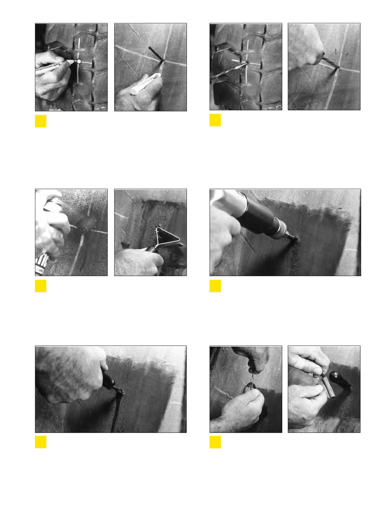
Locate and mark the injury on the outside and
REMOVE the object from the tire. Inspect the injury
1
2
inside of the tire.
to determine the location, size, and angle of
penetration. Probe into the injury and make sure that no
air infiltration exists or excessive rust has formed. Refer to
the Nail Hole Limitations Chart on Page126 to determine
repairability and to select the proper repair material. Use
Injury Sizing Tool if available. Make sure to measure the
injury to assure the damage does not exceed 3/8” (10
mm).
Apply rubber cleaner to the inner liner at the
Prepare the injury with the proper size carbide
3
4
injured area. While the area is still moist, use a
cutter on a low rpm drill (max. 1200 rpm).
rubber scraper to remove contaminating substances.
Following the direction of the injury, drill from the inside
out. Repeat this process three times. Repeat this
procedure from the outside of the tire to ensure damaged
steel and rubber are removed (be careful when drilling;
you do not want to make the injury any larger than
necessary).
Using a Spiral Cement Tool, cement the injury from
Place the wire puller in the middle of the black
5
6
the inside of the tire with Chemical Vulcanizing
exposed portion of the stem. Remove the
Fluid. Turn the tool in a clockwise direction both into and
protective poly from the stem and brush a light coat of
out of the tire. This step should be repeated 3 to 5 times.
Chemical Vulcanizing Fluid (cement) on this area. For
Leave the tool in the injury as you go to the next step.
lubrication, apply a coat of cement to the wire puller
where it contacts the stem.
127
Section Seven: Repairs and Retread
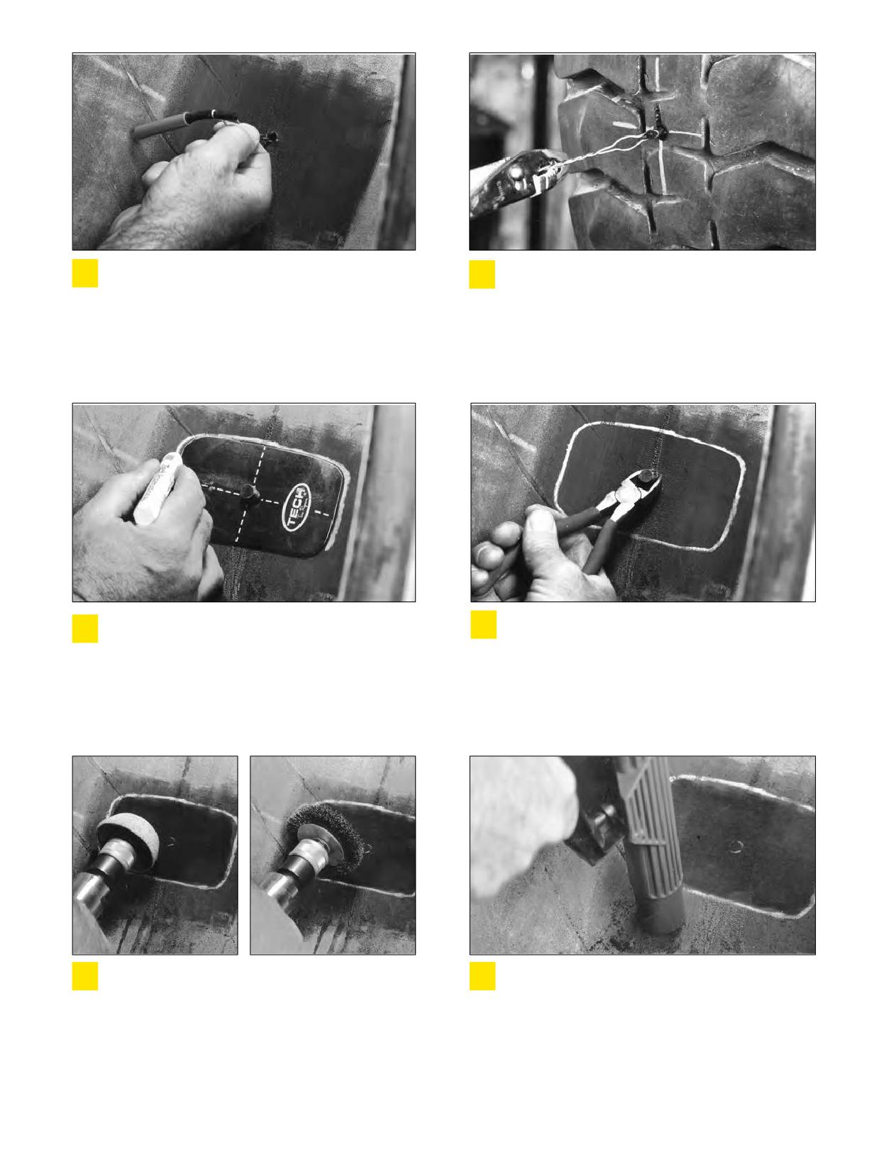
Remove spiral cement tool from the injury and
Grasp the wire puller from the outside of the tire
7
8
feed the small end of the wire puller through the
and begin pulling the stem into place. If the wire
injury from inside of the tire.
puller comes off, grasp the stem with a pair of pliers and
pull the stem until it fills the injury, exposing
approximately 1/2 inch (13 mm) of the gray cushion
bonding gum above the face of the tread.
On the inside of the tire, center the appropriate
Remove the template and cut off the stem 1/8 inch
9
10
repair unit template over the stem, make sure to
(3 mm) above the inner liner on the inside of the
correctly align the template in relationship to the tire
tire. NOTE: If you do not have a repair template, go to
beads, and draw a perimeter around the template.
this step and cut the stem; then using the correct sized
patch and centering it correctly on the injury - arrows
towards the beads - draw your perimeter approximately
1/2 inch larger than the repair patch.
Use a low rpm (max. 5000 rpm) buffer and
Vacuum all buffing dust and debris from the tire. If
11
12
texturizing wheel to mechanically buff the stem
the buffed surface is touched or contaminated after
flush to the inner liner. Then buff the outlined area to
cleaning the area, you must repeat Step 11 to guarantee
achieve an even RMA-1 or RMA-2 buffed texture. Use a
your surface is clean for proper repair bonding.
clean, soft wire brush, remove all dust and debris from
the buffed area.
128 Section Seven: Repairs and Retread
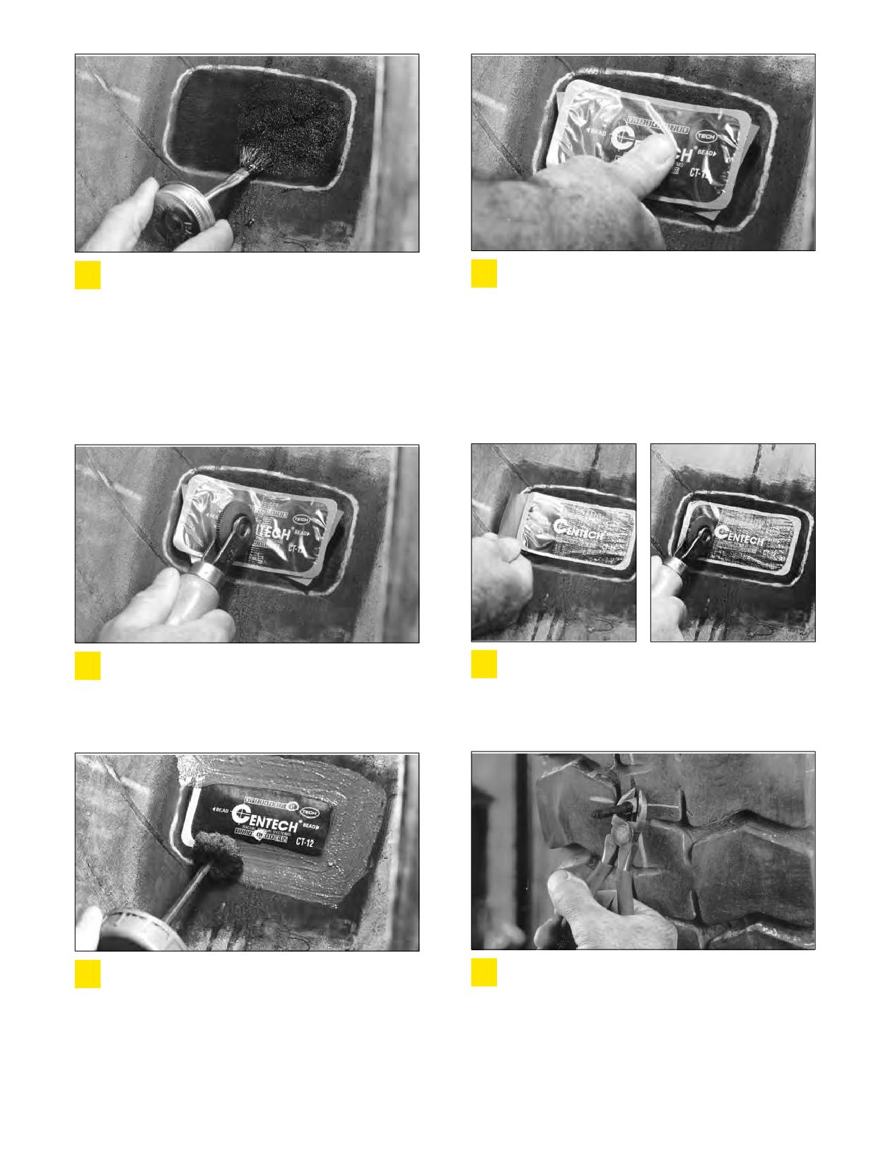
Using Chemical Vulcanizing Fluid (cement), brush
With the tire beads in a relaxed position, center the
13
14
a thin, even coat into the clean textured area. Allow
repair unit over the filled injury. Press the repair
3 to 5 minutes to dry; the vulcanizing cement should be
unit down into place over the injury. Make sure the
tacky. Areas with high humidity may require a longer dry
directional bead arrows on the repair unit are aligned
time. Make sure the cement used is compatible with the
with the beads of the tire, and press into place. Roll the
repair units you are installing.
protective poly back to the outer edges of the repair unit.
This enables you to handle the repair unit without
contaminating the bonding gum layer. You are now
ready to stitch the repair.
Stitch the repair unit, firmly pressing down from
Remove the rest of the poly backing. Stitch the
15
16
the center toward the outer edges. This will
repair unit from the center to the outer edges.
eliminate trapping air under the repair unit.
Remove the top clear protective poly.
To cover over-buffed areas in tubeless tires, apply
Cut the stem off on the outside of the tire 1/8 inch
17
18
Security Sealer to the outer edge of the repair unit
(3 mm) above the tire’s surface. The tire is now ready
and over-buffed area. If tube-type, cover the repair with
to be returned to service.
Tire Talc to prevent the repair from vulcanizing to the
tube.
Section Seven: Repairs and Retread
129
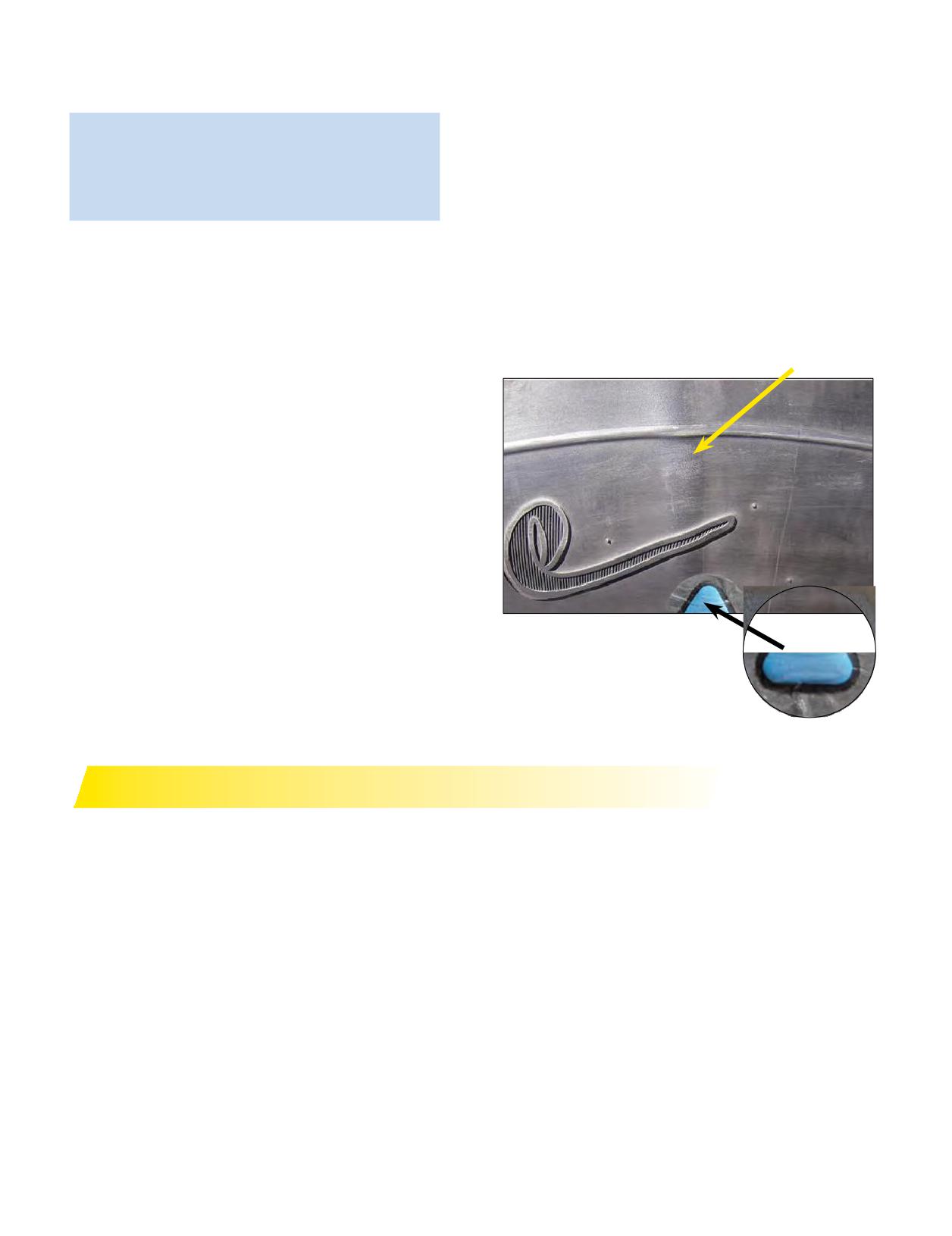
MICHELIN® X ONE® TIRES NAIL HOLE
BLUE IDENTIFICATION TRIANGLE
REPAIR METHOD INSTRUCTIONS
Tech Identification Triangles (IDTs): Tech International
has designed a blue identification triangle for placement
adjacent to a sidewall repair for easier identification
MICHELIN® X One® Tire
of acceptable bulges related to such a repair and not
• MICHELIN® X One® tires: There are no special
related to tire separation. Bulges 3/8” or less beyond
repair techniques or materials required when
the normal sidewall profile that are associated with
repairing a MICHELIN® X One® tire.
sidewall repairs of radial truck tires are permitted by the
U.S. Tire Manufacturers Association (USTMA) and have
Contact your local Michelin Representative or MRT(1)
been deemed acceptable by the Commercial Vehicle
Dealer if damage is beyond nail hole limits and requires a
Safety Alliance (CVSA). The Tech IDT is a triangular blue
section repair.
equilateral patch measuring 1.25” per side that is located
and vulcanized just above the tire rim’s flange area and
near the repair.
Acceptable Bulges 3⁄ 8” or Less
Blue Identification Triangle
RETREAD
Since MICHELIN® radial tires are manufactured to very
Refer to the MICHELIN® X One® Retread and Repair
precise tolerances, it is necessary for similar standards of
on Pages 102-104 for recommendations on retread
accuracy to be maintained during the retreading process.
guidelines.
Suitably designed modern equipment for radial tires must
Michelin Retread Technologies (MRT) Retread Designs
be provided in the retread shop. The proper tread designs,
are also available in MRT(1) Retread Quick Reference
tread width, tread compound, and tread depths, must be
Tread Guide (MYL44115) and/or the MICHELIN® Truck
selected according to the type of tire and its anticipated
Tire Data Book (MWL40731).(2)
service.
For more information, contact your local Michelin
The tire must be processed with precision to maintain
Representative or MRT Dealer.
the design characteristics of the MICHELIN® radial. As
there is very little margin for error when retreading radial
(1) MRT - Michelin Retread Technologies
tires, perfection should be the only standard acceptable.
(2) Documents subject to change.
130 Section Seven: Repairs and Retread
SECTION EIGHT
Diagonal (Bias or Cross)
Ply and Tube-Type
Section Eight
Diagonal (Bias Or Cross) Ply and
Tube-Type
131-142
THE DIAGONAL (BIAS OR CROSS) PLY
132-134
Definitions
Tube-Type Tire
Truck Tire Size Markings
Repair and Retread
Static and Low Speed Load and Pressure Coefficients
TRA (The Tire and Rim Association, Inc.) Standards
GENERAL INSTRUCTIONS FOR TUBE-TYPE TIRE
DEMOUNTING/MOUNTING
135-137
Selection of Proper Components and Materials
Tire and Wheel Lubrication
Preparation of Wheels and Tires
Storage
MOUNTING TUBE-TYPE TIRES
138-140
Mounting Tube-Type Tires Using Manual Spreaders
Mounting Tube-Type Tires Using Automatic Spreaders
Inflation of Tube-Type Tires
DEMOUNTING TUBE-TYPE TIRES
141-142
Section Eight: Diagonal (Bias or Cross) Ply and Tube-Type
131
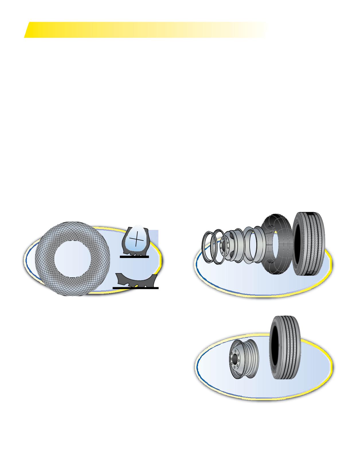
THE DIAGONAL (BIAS OR CROSS) PLY TIRE
DEFINITIONS
TUBE-TYPE TIRE
Diagonal (bias or cross) ply (or conventional) tires are
Tube Code: The proper MICHELIN® tube to be used
made up of a number of textile cords set on a bias (laid
with MICHELIN® tube-type tires is designated by the
diagonally), criss-crossing one another. Depending on the
nominal rim diameter followed by a code. Example: Tube
textile strength of the cord used (rayon, nylon, polyester,
for 10.00R20 Michelin is 20N (the R designates radial
and the required size of the tire, there could be from 6 to
construction).
20 plies in a bias-ply carcass. Without steel belts to stabilize
MICHELIN® tubes are made of butyl rubber and marked
the tread, the sidewall and tread work as one unit resulting
with the trade name “AIRSTOP®”. Because of the extreme
in distortion with deflection during each revolution.
flexibility of the MICHELIN® tire, it is recommended to use
This abrasive force creates scrub and generates heat,
an “AIRSTOP” tube. These tubes are made with an overlap
prematurely aging the components and shortening the life
splice that is stronger than the butt splice used in many
of the tire.
other tubes. Some MICHELIN® tube-type tires may be run
The number of cross-plies in a tire tends to stiffen its
with or without a tube. Contact Michelin to determine
walls, preventing sufficient flex under heavy load. This
tires that apply. Ensure tire is mounted on a sealed wheel if
causes lateral tread movement that impairs road grip and
mounted tubeless.
causes tread abrasion. The heat generated also stretches
Flap Code: When a flap is required, the proper size to use
the textile cords during the carcass life, allowing the casing
with MICHELIN® tires on each particular rim is designated
to grow and making it difficult to match new, used, and
by a code, the last two digits of which are the rim diameter
retreaded tires in dual configuration.
or rim width. Unless otherwise specified, the flap for the
Aspect Ratio example: 10.00-20 (dash (-) designates the
preferred rim is normally supplied with the tire. (e.g. 200-
diagonal (bias or cross) construction), aspect ratio = 100.
20L or 20 x 7.50)
Section height is the same as section width.
Locking Side Disc
Flap
Ring
Ring
Wheel
Tube and Valve
Tire
Tube-Type (Seven Components)
Wheel and Valve
Tire
Tubeless (Three Components)
132 Section Eight: Diagonal (Bias or Cross) Ply and Tube-Type
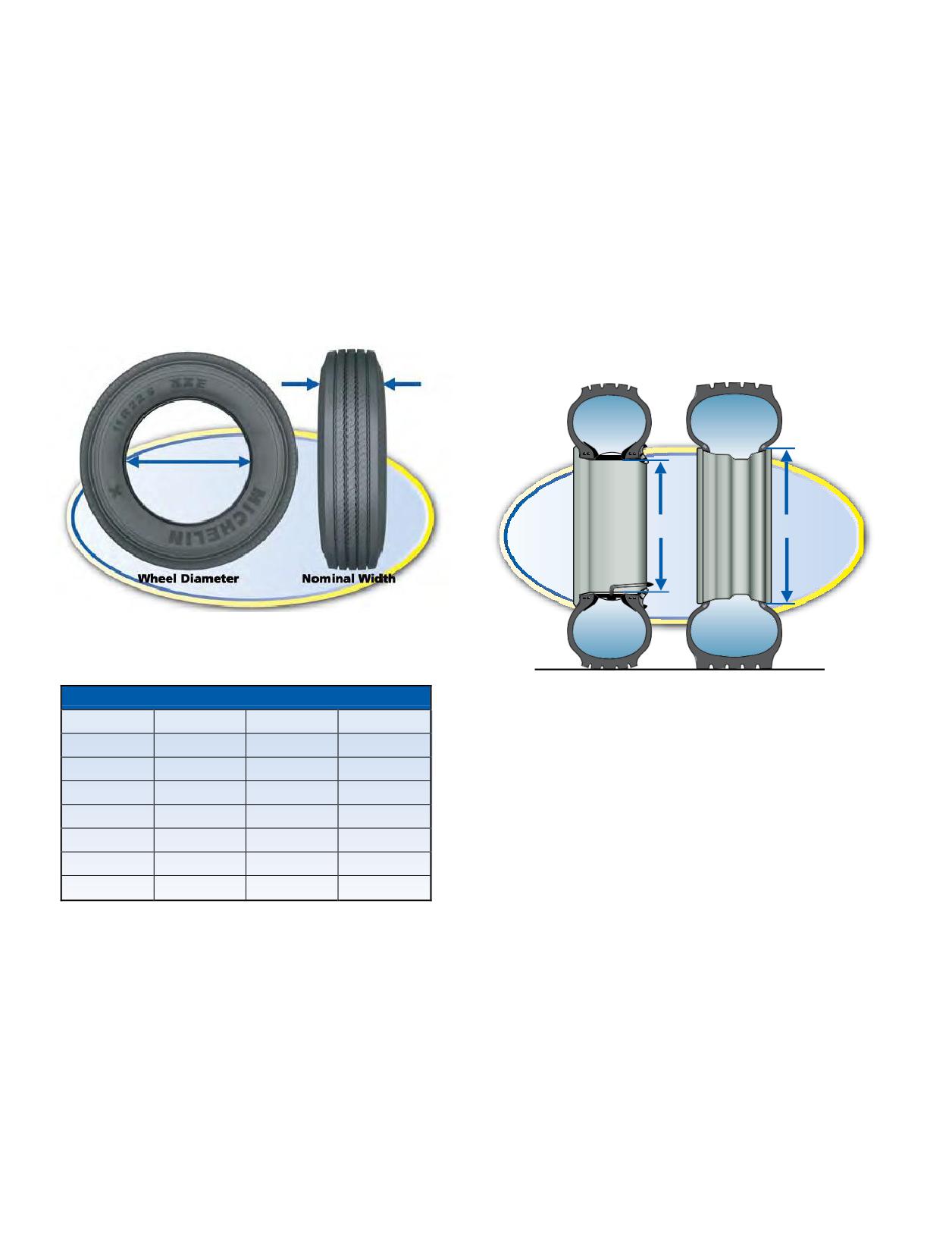
TRUCK TIRE SIZE MARKINGS
Note: A “rule-of-thumb” formula for finding equivalent
Most truck tire sizes are indicated by the section width
tubeless sizes from tube-type: Take the nominal section
in inches, followed by R for radial (dash (-) designates the
width and remove all figures after the decimal point. Round
diagonal (bias or cross) construction), followed by the wheel
up to next whole nominal section number and add 2.5 to
diameter in inches:
wheel diameter.
Example:
TUBE-TYPE
TUBELESS
TUBE-TYPE
TUBELESS
10.00R20
11R22.5
8.25R20
=
9R22.5
10.00 = nominal section
11 = nominal section
width in inches
width in inches
Nominal Cross Section
8.25
Remove
0.25
R = radial
R = radial
Add
1 to the 8
=
9
20 = wheel diameter
22.5 = wheel diameter
in inches
in inches
Wheel Diameter
20
Add 2.5 to Wheel Diameter
20 + 2.5
=
22.5
Thus we have 9R22.5 Tubeless.
Tube-Type
Tubeless
20"
22.5"
COMPARATIVE SIZES - STANDARD - LOW PROFILE
TUBE-TYPE
TUBELESS TYPE
MICHELIN
TRA*
8.25R15
9R17.5
8.25R20
9R22.5
235/80R22.5
245/75R22.5
REPAIR AND RETREAD
9.00R20
10R22.5
255/80R22.5
265/75R22.5
1. Follow proper procedures per your Michelin Retread
10.00R20
11R22.5
275/80R22.5
295/75R22.5
Technologies dealer.
11.00R20
12R22.5
2. Use bias repair units in bias tires and radial repair units
in radial tires.
10.00R22
11R24.5
275/80R24.5
285/75R24.5
3. When performing tube repairs, do not install the patch
11.00R22
12R24.5
on an inflated tube, and apply a tire talc to the patch
* The Tire and Rim Association, Inc.
and buffed area to prevent sticking to the inside of the
tire.
Section Eight: Diagonal (Bias or Cross) Ply and Tube-Type
133

STATIC AND LOW SPEED LOAD AND PRESSURE COEFFICIENTS
Never exceed the maximum load or pressure limits of the wheel. Exceeding the wheel limits can lead to
component failure, serious accident, injury or death.
TRA (THE TIRE AND RIM ASSOCIATION, INC.) STANDARDS
These Tables apply to tires only. Consult wheel manufacturer for wheel load and inflation capacities.
Load limits at various speeds for radial ply
truck-bus tires used on improved surfaces. (1)
A. METRIC AND WIDE BASE TIRES
B. CONVENTIONAL TIRES
The service load and minimum (cold) inflation must
The service load and minimum (cold) inflation must
comply with the following limitations unless a speed
comply with the following limitations unless a speed
restriction is indicated on the tire.*
restriction is indicated on the tire.*
Speed Range
Inflation
Speed Range
Inflation
% Load Change
% Load Change
(mph)
Pressure Change
(mph)
Pressure Change
11 thru 20
+17%
+15 psi
11 thru 20
+32%
+15 psi
6 thru 10
+25%
+20 psi
6 thru 10 (2)
+60%
+30 psi
2.6 thru 5
+45%
+20 psi
2.6 thru 5 (2)
+85%
+30 psi
Creep thru 2.5
+55%
+20 psi
Creep thru 2.5 (2)
+115%
+30 psi
Creep (2)
+75%
+30 psi
Creep (2,3)
+140%
+40 psi
Stationary
+105%
+30 psi
Stationary (2)
+185%
+40 psi
Note: For bias ply tires please consult the TRA Year Book.
(1) These load and inflation changes are only required when exceeding the tire manufacturer’s rated speed for the tire.
(2) Apply these increases to Dual Loads and Inflation Pressures.
(3) Creep - Motion for not over 200 feet in a 30-minute period.
Note 1:
The inflation pressures shown in the referenced tables are minimum cold pressures for the various loads listed.
Higher pressures should be used as follows:
A. When required by the above speed/load table.
B. When higher pressures are desirable to obtain improved operating performance.
For speeds above 20 mph, the combined increases of A and B should not exceed 20 psi above the inflation specified for the maximum load of the tire.
Note 2:
Load limits at various speeds for:
Tires used in highway service at restricted speed.
Mining and logging tires used in intermittent highway service
*Exceeding the legal speed limit is neither recommended nor endorsed.
134 Section Eight: Diagonal (Bias or Cross) Ply and Tube-Type
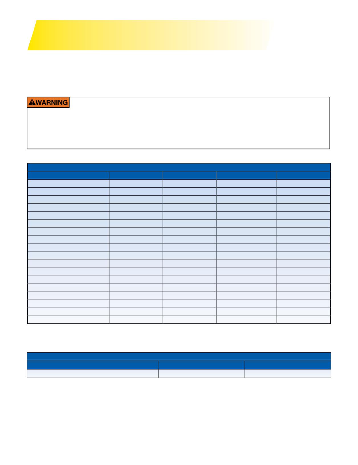
GENERAL INSTRUCTIONS
FOR TUBE-TYPE DEMOUNTING / MOUNTING
A tire cannot perform properly unless it is mounted properly on the correct size wheel. The following are general
instructions for demounting and mounting MICHELIN® tube-type tires. For detailed instructions on mounting and
demounting truck tires on particular types of wheels, refer to the instructions of the wheel manufacturer or the USTMA
(U.S. Tire Manufacturers Association) wall charts.
Do not reinflate any tires that have been run underinflated or flat without careful inspection for
damage. If run-flat damage is detected, scrap the tire. A tire is considered run-flat if it is found to be
less than 80% of normal recommended operating pressure. This can result in serious injury or death.
The tire may be damaged on the inside and can explode during inflation. The wheel parts may be
worn, damaged, or dislodged and can explosively separate.
TUBES AND FLAPS FOR COMMERCIAL TRUCK TIRES
SIZE
TUBE
TUBE MSPN
FLAP
FLAP MSPN
7.50R15
15/16J
*73993
15x6.00
62152
8.25R15
15/16J
*73993
15x6.00
62152
10.00R15
15P
04560
15x7.50
58753
9.00R16
16N
17786
16x6.00D
94605
7.50R17
17K
26362
17X6.00D
45608
335/80R20
20P
06934
20x10.00
47501
275/80R20
20P
06934
20x10.00
47501
365/80R20
20Q
39144
20x10.00
47501
15.5/80R20
20S
32420
20x10.00
47501
14.00R20
20S
32420
20x10.00
47501
14.5R20
20S
32420
20x10.00
47501
395/85R20
20S
32420
20x10.00
47501
365/85R20
20S
32420
20x10.00
47501
16.00R20
20V
32961
20x10.00
47501
10.00R20
20N
17078
20x7.50
44274
11.00R20
20P
06934
20x8.50
49781
12.00R20
20Q
39144
20x8.50
49781
12.00R24
24Q
11708
24/25x8.50
48842
* Use tube MSPN 73993 for CAT Forklifts (15/16J with valve 1221), other truck / industrial applications,
use MSPN 17542 (15/16J with valve 570). MSPN 17542 uses same flap and is the same price as MSPN 73993.
MOUNTING LUBRICANT
Product
Size
Product code
Tigre grease
4 Kg
25817
Section Eight: Diagonal (Bias or Cross) Ply and Tube-Type
135
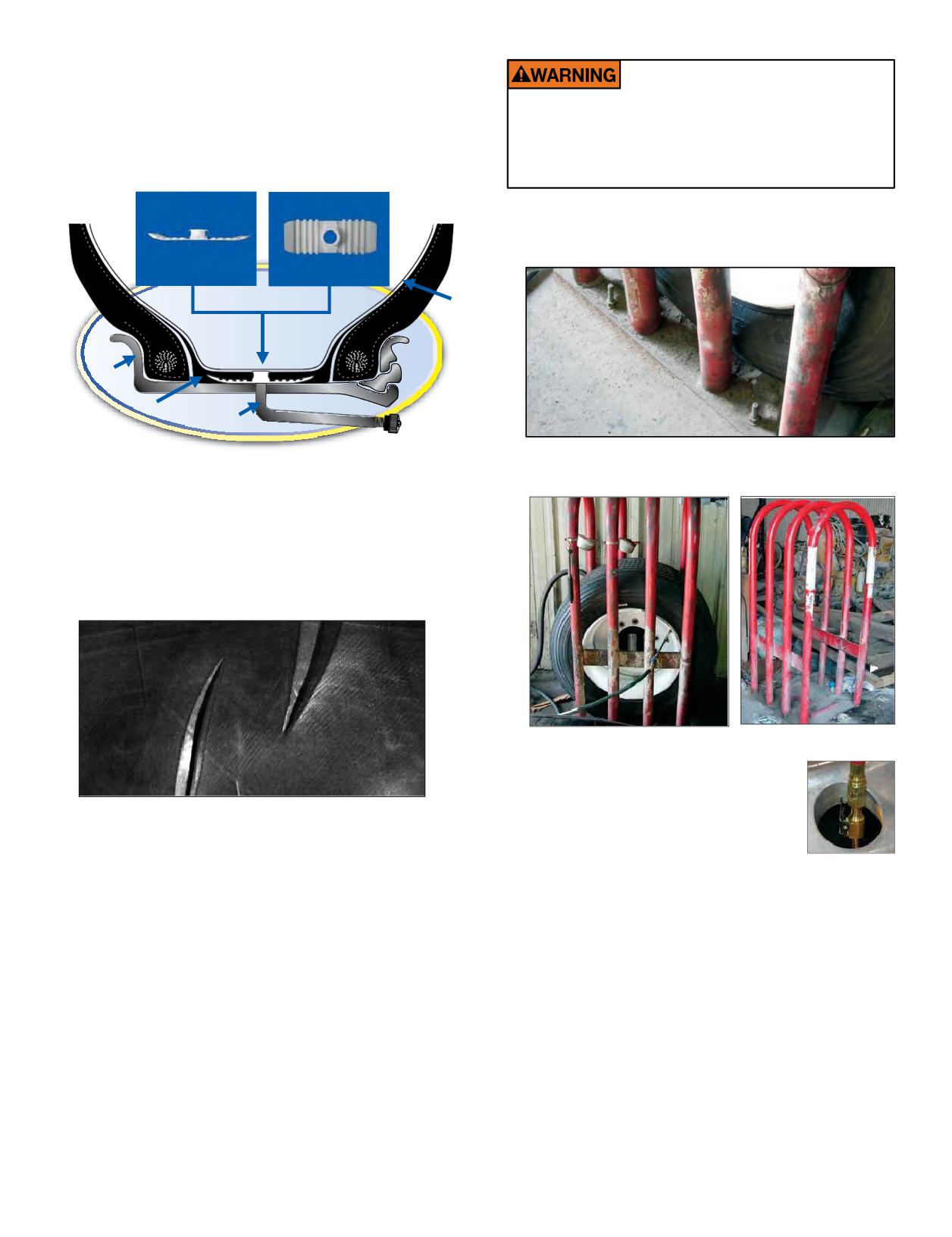
1. SELECTION OF PROPER COMPONENTS
AND MATERIALS
It is imperative to follow all of the following
a. All tires must be mounted with the proper MICHELIN®
inflation safety recommendations. Failure to do so
tube and flap (if required) and wheel as indicated in
will negate the safety benefit of using an inflation
the specification tables on Page 135. For complete tire
cage or other restraining device and can lead to
specifications, refer to application specific data books.
serious injury or death.
2. INFLATION SAFETY RECOMMENDATIONS
a. Do not bolt the inflation cage to the floor or nor add any
other restraints or accessories.
Nylon Plate
Tube
Rim
Flap
Valve
b. The inflation cage should be placed at least 3 feet from
b. Make certain that wheel components are properly
anything, including a wall.
matchedandof the correct dimensions for the tire.
c. Always fit a new MICHELIN® tube in a new mounting.
Since a tube will exhibit growth in size through normal
use, an old tube used in a new mounting increases
the possibility of tube creasing and chafing, possibly
resulting in failure.
c. Never stand over, or in front of a tire when inflating.
d. Always use a clip-on chuck and a
sufficiently long air hose between the
Pinched tube
in-line gauge and the chuck to allow the
service technician to stand outside the
d. Always install a new flap in a new mounting. A flap,
trajectory zone when inflating.
Clip-on Chuck
through extended use, becomes hard and brittle. After
a limited time, it will develop a set to match the tire and
Trajectory zone means any potential path or route that
wheel in which it is fitted. Therefore, it will not exactly
a wheel component may travel during an explosive
match a new tire and wheel combination.
separation or the sudden release of the tire pressure,
e. Always install new valve cores andmetal valve caps
or an area at which the blast from a single piece wheel
containing plastic or rubber seals. For tires requiring
may be released. The trajectory may deviate from paths
O-rings, be sure to properly install a new silicone
that are perpendicular to the assembled position of the
O-ring at every tire change.
wheel at the time of separation or explosion. See Rubber
f. Always use a safety device such as an infl
cage
Manufacturers Association Tire Information Service
or other restraining device that will constrain all
Bulletin Volume 33, Number 4 for more information.
wheel components during an explosive separation
of a multi-piece wheel, or during the sudden release
Note: Safety cages, portable and/or permanent, are also
of the contained air of a single piece wheel that is in
available for inflation of the MICHELIN® X One® tire
compliance with OSHA (Occupational Safety and Health
assemblies.
Administration) standards.
136 Section Eight: Diagonal (Bias or Cross) Ply and Tube-Type
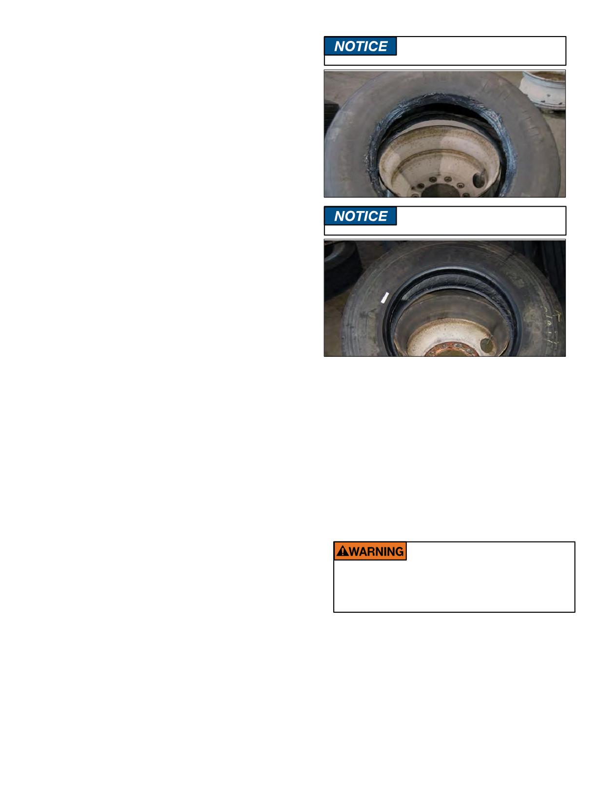
3. TIRE AND WHEEL LUBRICATION
Avoid using excessive amounts of
It is essential that an approved tire mounting lubricant
lubricants.
be used. Preferred materials for use as bead lubricants
are vegetable based and mixed with proper water ratios
per manufacturer’s instructions. Never use antifreeze,
silicones, or petroleum-base lubricants as this will damage
the rubber. Lubricants not mixed to the manufacturer’s
specifications may have a harmful effect on the tire and
wheel.
The lubricant serves the following three purposes:
• Helps minimize the possibility of damage to the tire
beads from the mounting tools.
• Helps ease the insertion of the tire onto the wheel by
lubricating all contacting surfaces.
Dry mounting should be avoided.
• Assists proper bead seating (tire and wheel centering)
Use approved lubricants.
and helps to prevent eccentric mountings.
The MICHELIN® product, Tigre Grease 80, MSPN
25817, is specifically formulated for commercial truck
tire mounting. It can be obtained through any authorized
Michelin Truck Tire dealer or by contacting Michelin
Consumer Care (1-888-622-2306).
Apply a clean lubricant to all portions of the tire bead
area and the exposed portion of the flap using sufficient
but sparing quantities of lubricant. Also, lubricate the
entire rim surface of the wheel. Avoid using excessive
amountsof lubricant, which can become trapped
deformation of flanges. Using a file and/or emery cloth,
between the tire and tube and can result in tube damage
smooth all burrs, welds, dents, etc. that are present on
and rapid tire pressure loss.
the tire side of the wheel. Inspect the condition of bolt
CAUTION: It is important that tire lubricant be clean and
holes on the wheels. Rim flange gauges and ball tapes
free of dirt, sand, metal shavings, or other hard particles.
are available for measuring wear and circumference of
The following practice is recommended:
aluminum wheels.
a. Use a fresh supply of tire lubricant each day, drawing
c. Remove rust with a wire brush and apply a rust
from a clean supply source and placing the lubricant in
inhibiting paint on steel wheels. The maximum paint
a clean portable container.
thickness is 0.0035” (3.5 mils) on the disc face of the
b. Provide a cover for the portable container and/or other
wheel.
means to prevent contamination of the lubricant when
d. Remove any accumulation of rubber or grease stuck to
not in use. For lubricants in solution, we suggest the
the tire, being careful not to damage it. Wipe the beads
following method, which has proven to be successful
down with a dry rag.
in helping to minimize contamination and prevent
excess lubricant from entering the tire casing: provide
a special cover for the portable container that has a
Never weld or apply heat to a wheel on which a
tire is mounted. This may lead to a destructive
funnel-like device attached. The small opening of the
increase in air pressure, tire failure, injury or
funnel should be sized so that when a swab is inserted
death.
through the opening into the reserve of lubricant and
then withdrawn, the swab is compressed, removing
STORAGE
excess lubricant. This allows the cover to be left in place
Serious problems can occur with tube-type tires when
providing added protection. A mesh false bottom in the
they are mounted with water trapped between the tire and
container is a further protection against contaminants.
tube. Under pressurization, the liquid can pass through the
The tire should be mounted and inflated promptly
inner liner and into the casing plies. This
before lubricant dries.
can result in casing deterioration and sudden tire failure.
4. PREPARATION OF WHEELS AND TIRES
Most failures of this nature are due to improper storage.
a. Always wear safety goggles or face shields when buffing
This is a particular problem with tube-type tires because
of the difficulty in detecting the water, which has collected
or grinding wheels.
b. Inspect wheel assemblies for cracks, distortion, and
between the tire and tube.
Section Eight: Diagonal (Bias or Cross) Ply and Tube-Type
137
MOUNTING TUBE-TYPE TIRE
Reassembly and inflation of mismatched parts can result in serious injury or death. Just because parts
fit together does not mean that they belong together. Check for proper matching of all wheel parts
before putting any parts together. Inspect the tire and the wheel for any damage that would require
them to be placed out of service.
Mismatching tire and wheel components is dangerous. A mismatched tire and wheel assembly
may explode and can result in serious injury or death. This warning applies to any combination of
mismatched components and wheel combinations. Never assemble a tire and wheel unless you have
positively identified and correctly matched the parts.
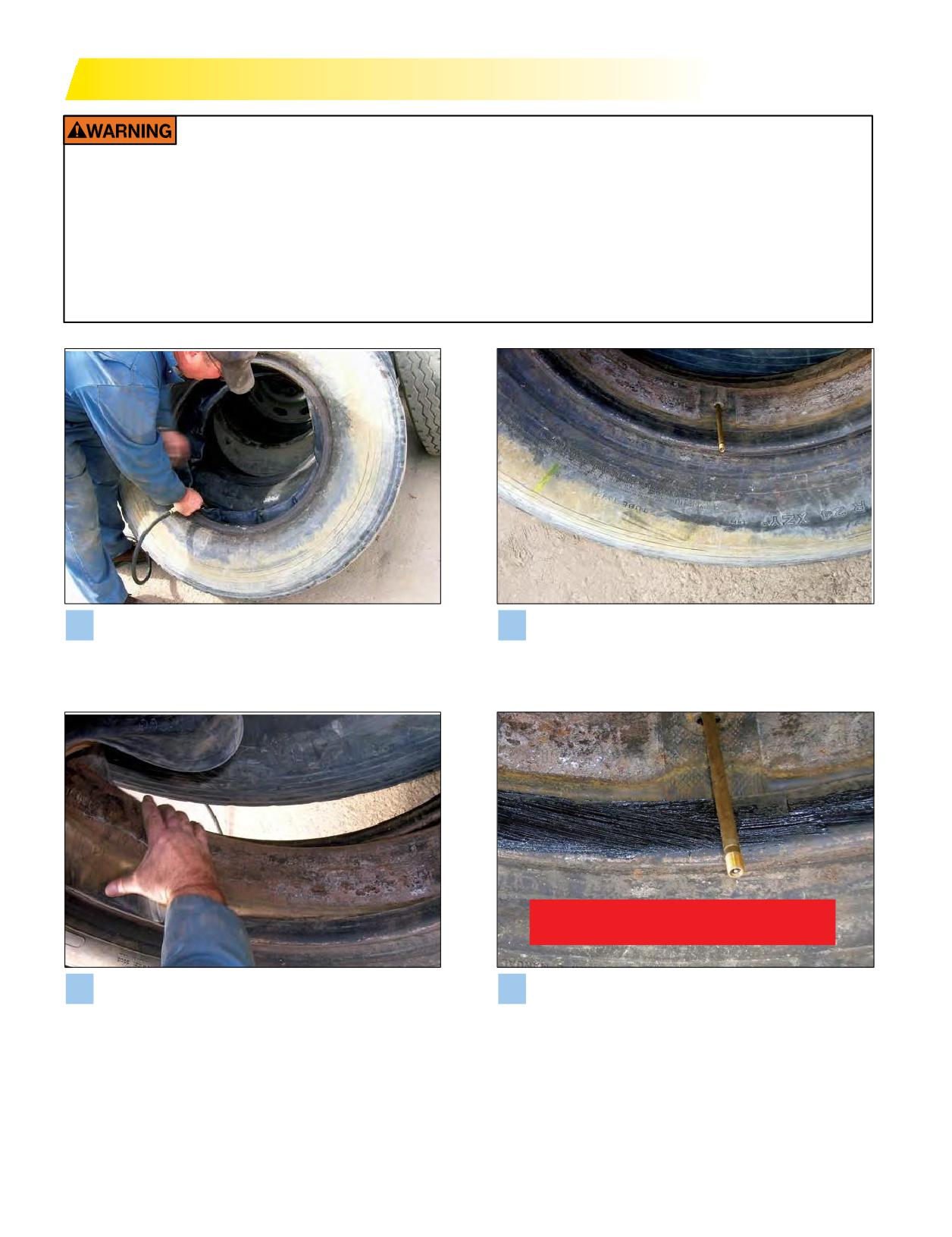
Insert the proper size MICHELIN® tube into the tire
Insert the valve through the flap valve hole. (Make
1
2
and partially inflate (3 psi) to round out the tube
sure the reinforced patch that is directly over the
(with larger sizes it may be necessary to use bead
flap valve hole is facing outwards.) Then insert the
spreaders - see below for mounting instructions).
remainder of the flap into the tire.
NOT TO EXCEED 3 PSI!
Check the flap wings to ensure against folding. This
Inflate the tube until the flap is secured against the
3
4
is easily accomplished by placing your hand into
tire wall and the beads start to spread apart, making
one tire side, then the other, and then running your
sure not to exceed 3 psi.
hand along the entire flap wing.
138 Section Eight: Diagonal (Bias or Cross) Ply and Tube-Type
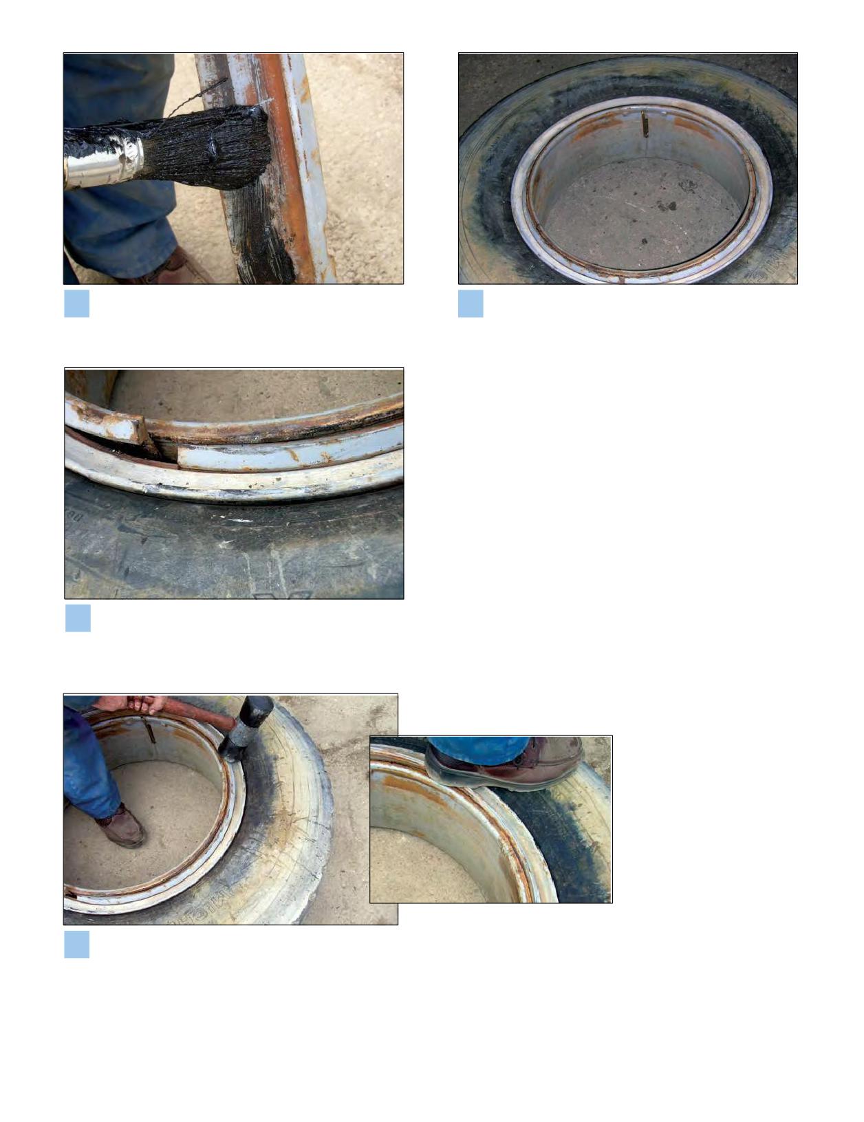
Apply a proper tire lubricant to both beads, exposed
Lay the rim flat on the floor with the gutter side up.
5
6
flap, and fully to the rim. Make sure that excess
Place tire, tube, and flap on the rim, taking care to
lubricant does not run down into the tire.
center the valve in the slot.
Two-Piece Wheels
For two-piece wheels, place the side ring on the rim
base so that the ring split is opposite the valve stem by
placing the leading end (end without the notch) of the
ring into the groove in the rim, and progressively walk the
side ring into place. Ensure the ring is fully seated in the
gutter.
Three-Piece Wheels
For three-piece wheels, place the side ring on the
rim base and stand on the ring to position it below the
gutter wheel base. Snap the leading end (end without the
notch) of the lock ring into the gutter of the rim base, and
progressively walk the lock ring into place. Ensure the
7 Three piece wheels positioned.
ring is fully seated in the gutter.
8 Snap and walk ring into place.
Section Eight: Diagonal (Bias or Cross) Ply and Tube-Type
139
MOUNTING OF TUBE-TYPE TIRES USING
INFLATION OF TUBE-TYPE TIRES
MANUAL SPREADERS
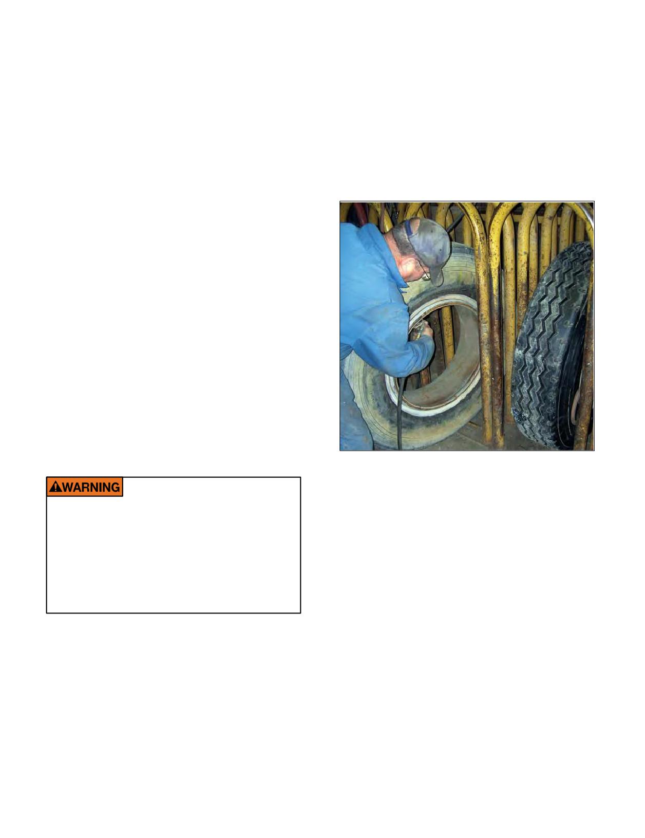
1. An inflation line with an extension (30” minimum),
1. Follow Steps 1 through 3 of the “Mounting of Tube-
in-line gauge, and a clip-on valve chuck should be used
Type Tires.” However, before inserting the flap into
for inflation. Remove valve core and lay the assembly
the tire, position two bead spreaders in the following
flat on the ground. Using an approved restraining
manner:
device, inflate partially to seat beads to no more than 3
a. Place the first at a 90° angle to the valve. (Flap is
psi. While the tire is still in the restraining device, make
positioned between the spreader and the tube.)
sure all wheel components are centered and locked
b. Place the second directly opposite the first.
properly. If not, the tire must be deflated, broken down,
c. Spread the beads and insert the flap.
relubricated and reinflated. Do not attempt to seat the
d. Close the beads, remove spreaders.
lock ring by means of a hammer.
2. Follow Steps 4 through 8 of the “Mounting of
Tube-Type Tires.”
MOUNTING OF TUBE-TYPE TIRES USING
AUTOMATIC SPREADERS
1. Spread the tire beads.
2. Inflate the tube to approximately 3 psi.
3. Insert the tube into the tire.
4. Insert the valve through the flap valve hole.
(As mentioned, the flap reinforced valve area must face
outwards.) Insert the remainder of the flap into the tire.
5. Close the beads.
6. Apply a proper tire lubricant to the inside and outside
surfaces of both beads and to that portion of the flap
that appears between the beads. Make sure that excess
lubricant does not run down into the tire.
7. Follow Steps 4 through 8 of the “Mounting of Tube-
Type Tires.”
2. Deflate the tire by removing the inflation line. This is to
allow the tube to relax, thus, eliminating any wrinkles
or uneven stretching that may have occurred during
Do not reinflate any tires that have been run
primary inflation.
underinflated or flat without careful
3. With the valve core still removed, place the dual and
inspection for damage. Unseen internal
wheel assembly into an approved safety cage or
damage may lead to failure, injury or death.
other approved restraining device meeting OSHA
(Occupational Safety and Health Administration)
If run-flat damage is detected, scrap the tire.
A tire is considered run-flat if it is found to
standards, and reinflate the tire to the pressure
be less than 80% of normal recommended
shown on the sidewall in order to ensure proper bead
operating pressure.
seating. Then adjust the tire to the proper operating
pressure. Never stand over a tire or in front of a tire
when inflating. Always use a clip-on valve chuck with
an in-line valve with a pressure gauge or a presettable
regulator and a sufficient length of hose between the
clip-on chuck and in-line valve (if one is used) to allow
the employee to stand outside the trajectory path when
inflating. USTMA (U.S. Tire Manufacturers Association)
requires that all steel sidewall radial tires are inflated
without a valve core.
4. Reinspect the assembly for proper positioning and
seating of all components.
5. Check for leaks, and install a suitable valve cap.
140 Section Eight: Diagonal (Bias or Cross) Ply and Tube-Type
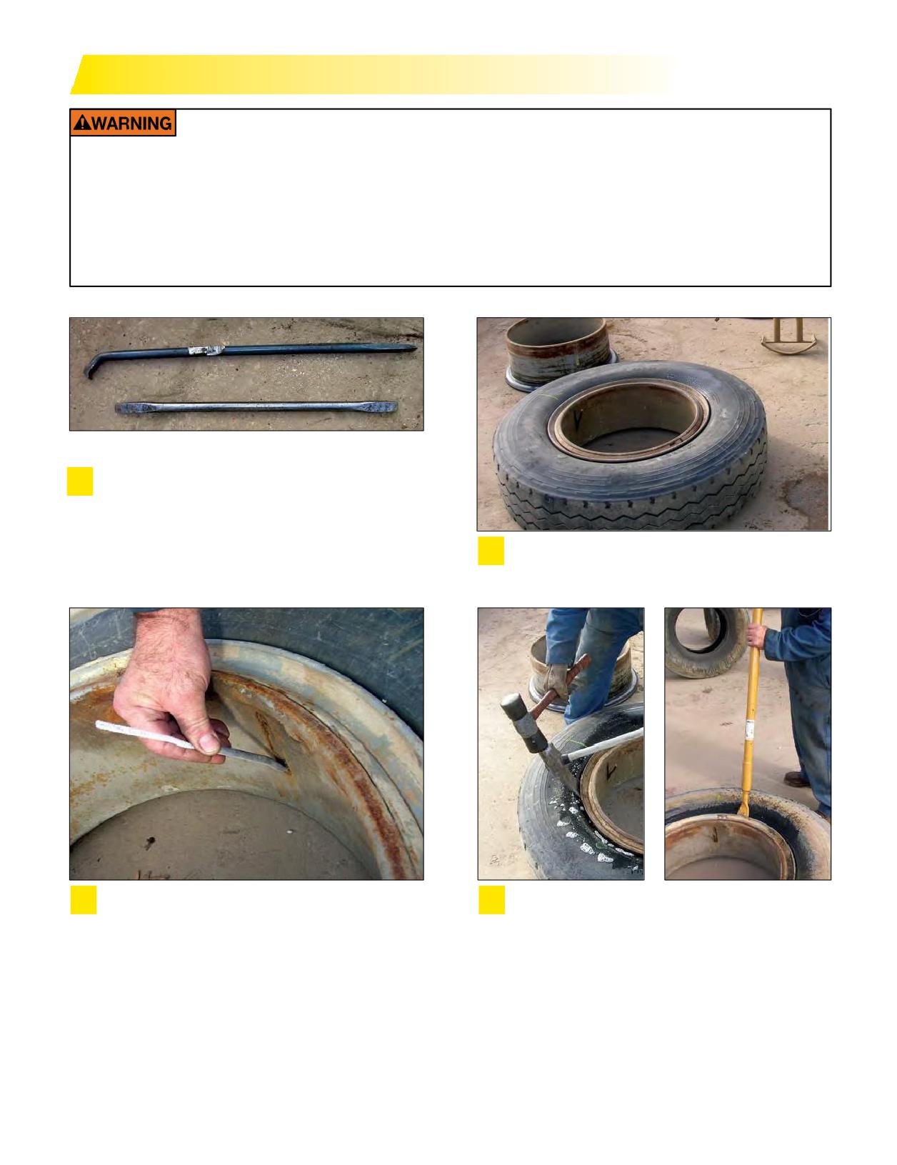
DEMOUNTING TUBE-TYPE TIRES
Any inflated tire mounted on a wheel contains explosive energy. The use of damaged, mismatched, or
improperly assembled tire and wheel parts can cause the assembly to burst apart with explosive force.
If you are struck by an exploding tire, wheel part, or the blast, you can be seriously injured or killed. Do
not attempt to dismount the tire while the assembly is still installed on the vehicle. Use proper tools
to demount or mount wheel parts. Never use a steel hammer to seat wheel parts - use only rubber,
plastic, or brass-tipped mallets. Striking a wheel assembly with a hammer of any type can damage the
tire or wheel and endanger the installer. Use a steel duck bill hammer only as a wedge. Do not strike
the head of a hammer with another hard-faced hammer - use a rubber mallet.
Rim Tools
Before loosening any nuts securing the tire and wheel
1
assembly to the vehicle, remove the valve core and
deflate completely. If working on a dual assembly,
completely deflate both tires. Run a wire or pipe
Remove the tire and wheel assembly from the
cleaner through the valve stem to ensure complete
2
vehicle and place on the floor with the side ring up.
deflation. This is to prevent a possible accident.
Run a wire or pipe cleaner through the valve stem
Apply lubricant to all surfaces of the bead area of
3
4
to clear the valve stem.
the tire. Use the duck bill hammer, with the rubber
mallet as a wedge, or a slide hammer.
Section Eight: Diagonal (Bias or Cross) Ply and Tube-Type
141
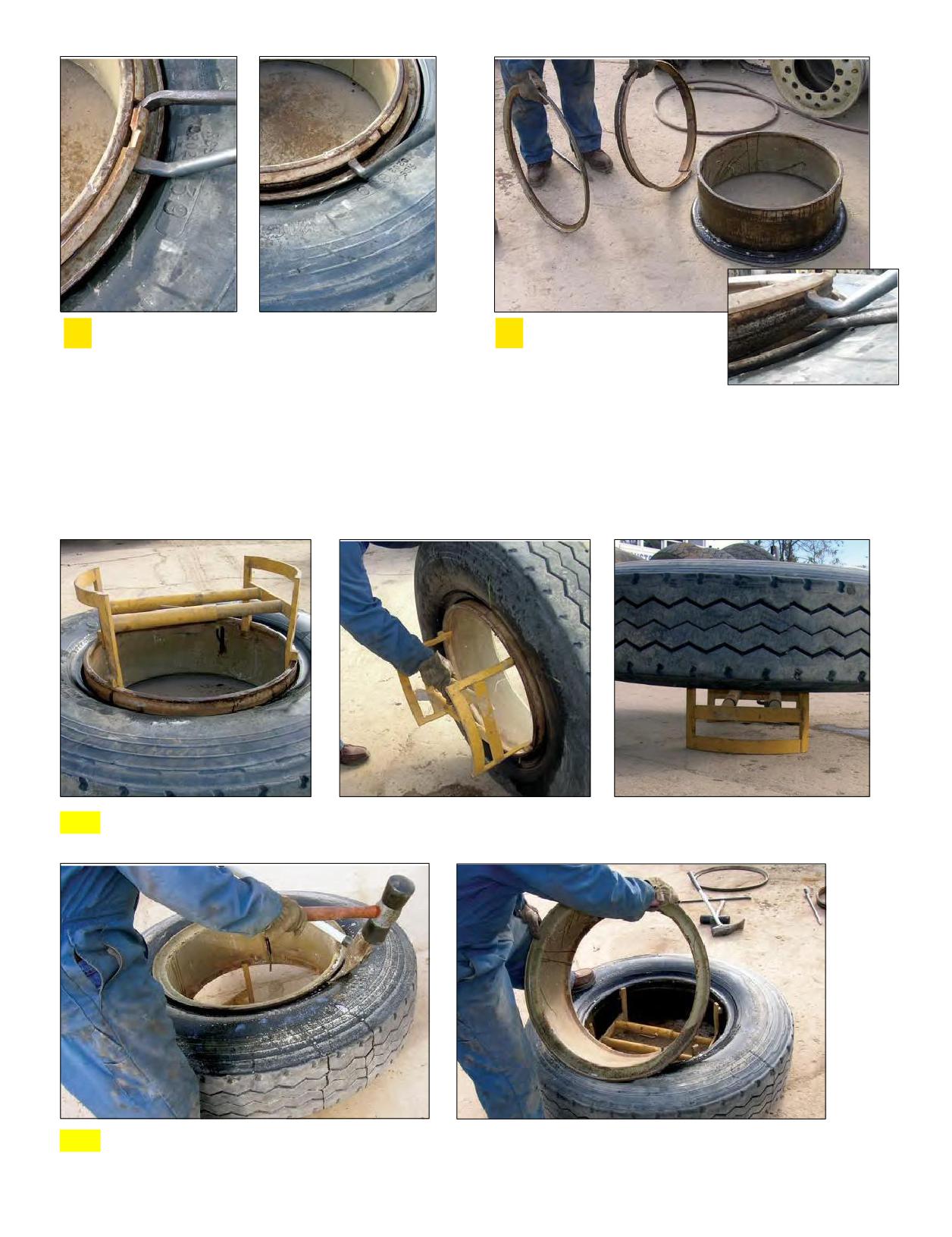
For two-piece wheels, remove the side ring by
For three-piece wheels,
5
6
pushing the tire bead down. Insert the tapered end
remove the lock ring by
of the rim tool into the notch and pry the side ring
pushing the side rings and
out of the gutter. Pry progressively around the tire
the tire bead down. Insert
until the side ring is free of the gutter.
the tapered end of the rim tool into the notch near
the split in the lock ring, push the tool downward,
and pry the lock ring outward to remove the gutter
from the base. Use the hooked end of the rim tool
progressively around the tire to complete the
removal, then lift off the side ring.
7 Turn the assembly over.
8 Unseat the remaining tire bead from the rim, and lift the rim from the tire.
142 Section Eight: Diagonal (Bias or Cross) Ply and Tube-Type
SECTION NINE
Tire Damage
EFFECT & CAUSE
All scrap tire failures are cause and effect related. In the
majority of the situations, it is the effect that we first see when
we look at the tire damage. However, tire condition “effects”
mayhavemanycauses. Often apattern canbefound thatmay
point to changes needed to avoid future scrap failures of this
nature. The majority of tubeless commercial scrap conditions
are found in the following damagecategories:
Section Nine
Tire Damage
143-158
EFFECT AND CAUSES
143
TIRE INSPECTION
144-145
RUN-FLAT
146-147
AIR INFILTRATION
148-151
The Use of Internal Balancing Materials and/or
Coolants in MICHELIN® Truck Tires
PINCH SHOCK
152
MINIMUM DUAL SPACING
152
IMPACT DAMAGE
153
FATIGUE RELATED DAMAGE
154
BEAD DAMAGE
155
ADDITIONAL CAUSES: REPAIRS AND
RETREADING CONDITIONS
156-157
SCRAP INSPECTION FORM
158
Section Nine: Tire Damage
143
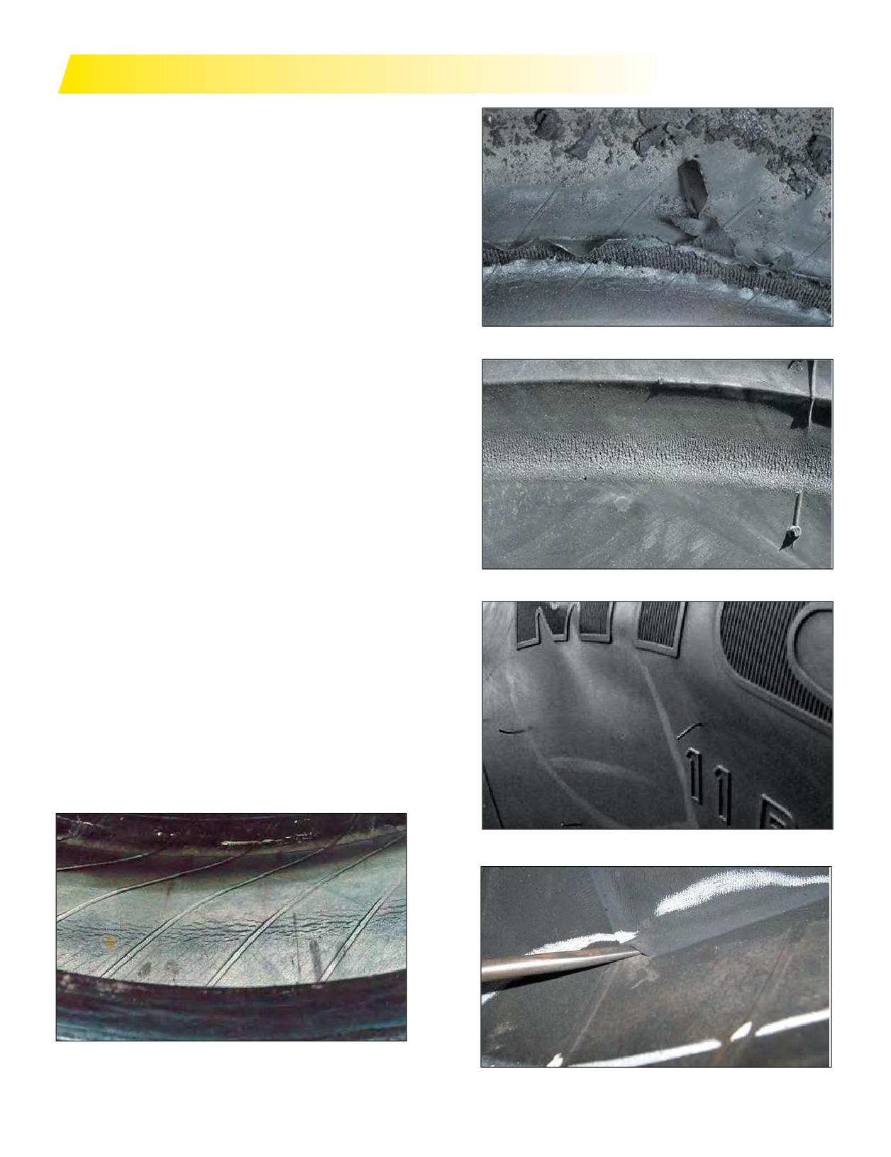
TIRE INSPECTION
TIRE INSPECTION
Any tire that is determined or suspected to be run-flat,
should be inspected thoroughly prior to returning to service.
Tire inspection should always include a thorough inspection
of both sidewalls and inner liner, as this may reveal any
potential damage condition that would cause the tire to
become scrap. Inner liner examination for creases, wrinkling,
discoloration, or insufficient repairs, and exterior examination
for signs of bumps or undulations, as well as broken cords,
could be potential out of service causes.
Look for wrinkling, discoloration, cracking, and/or
degradation of theinnerliner. Any breach to theinnerliner
Inner Liner Damages
can result in the introduction of moisture to the casing and
subsequent corrosion. If any signs of run-flat exist to the inner
liner, the tire should be made unusable and scrapped.
Abrasion marks on the sidewall due to road contact and/
or creases in the sidewall are another indicator of run-flat.
Feel for soft spots in the sidewall flex area. Using an indirect
light source helps identify sidewall irregularities by producing
shadows at the ripples and bulges. Look for protruding wire
filaments indicating broken sidewall cords.
All repair patches should be inspected for lifting, cracks,
splits, and general condition.
Proper OSHA (Occupational Safety and Health
Administration) regulations must be followed when putting
Abrasion Marks on the Sidewall
any tire and wheel back in service. After the tire has been
inflated to 20 psi in a safety cage, it should undergo another
sidewall inspection for distortions, undulations, or popping
noise indicating a breaking of the steel cords. If this is the
case, immediately deflate the tire and scrap. If no damage is
detected, continue to inflate to the maximum pressure marked
on the sidewall. Inspect the sidewall from a distance looking for
distortions and/or undulations, and listen for a popping noise.
If none exist, then insert valve core and return tire to service
after adjusting the pressure.
Ripples or Bulges in the Sidewall Flex Area
Potential Zipper Rupture
Patch Lifting
144 Section Nine: Tire Damage
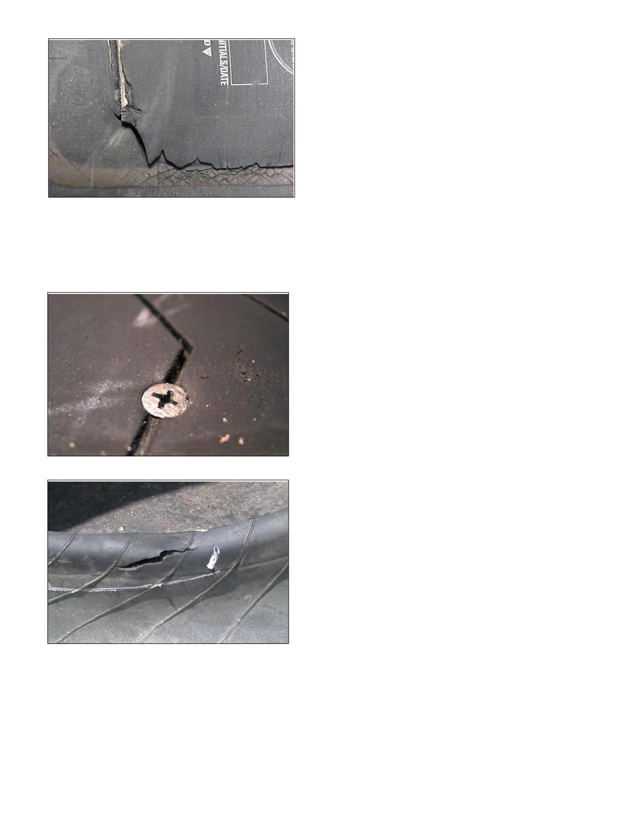
Ifnone of these conditions exist, the U.S. Tire
Manufacturers Association (USTMA) suggests the following
procedure for returning the tire to service.
1. Place the tire and wheel assembly in an approved
inflation safety cage*. Remain outside of the tire’s
trajectory. Do not place hands in the safety cage while
inspecting the tire or place head close to the safety cage.
After properly seating the beads, with the valve core
removed, adjust the tire to 20 psi, using a clip-on air
chuck with a pressure regulator and an extension hose.
Patch Cracking
2. Inspect themounted tire inflated to 20 psi for
distortions or undulations (ripples and/or bulges).
Listen for popping sounds. IF ANY OF THESE
CONDITIONS ARE PRESENT, THE TIRE SHOULD BE
Remove and repair all penetrating objects and check
MADE UNUSABLE AND SCRAPPED. If none of these
the beads for damage that may have occurred during
conditions are present, proceed to the next step.
removal.
3. With the valve core still removed,inflate the tire
to 20 psi over the normal recommendedoperating
pressure. During this step, if any of above conditions
appear, immediately stop inflation. DO NOT EXCEED
MAXIMUM PRESSURE SPECIFICATION FOR THE
WHEEL.
4. Before removing the tire and wheel assembly from
the safety cage, reduce the inflation pressure to the
recommended normal operating pressure. Remain
outside of the tire’s trajectory zone.
Penetrating Objects
* Occupational Safety and Health Administration Standard
1910.177 requires all tubeless and tube-type medium and large
truck tires be inflated using a restraining device or barrier (e.g.,
safety cage that conforms to OSHA standards), and using a clip-on
chuck with a pressure regulator and an extension hose.
Bead Damage Caused by Mounting/Dismounting
Section Nine: Tire Damage
145
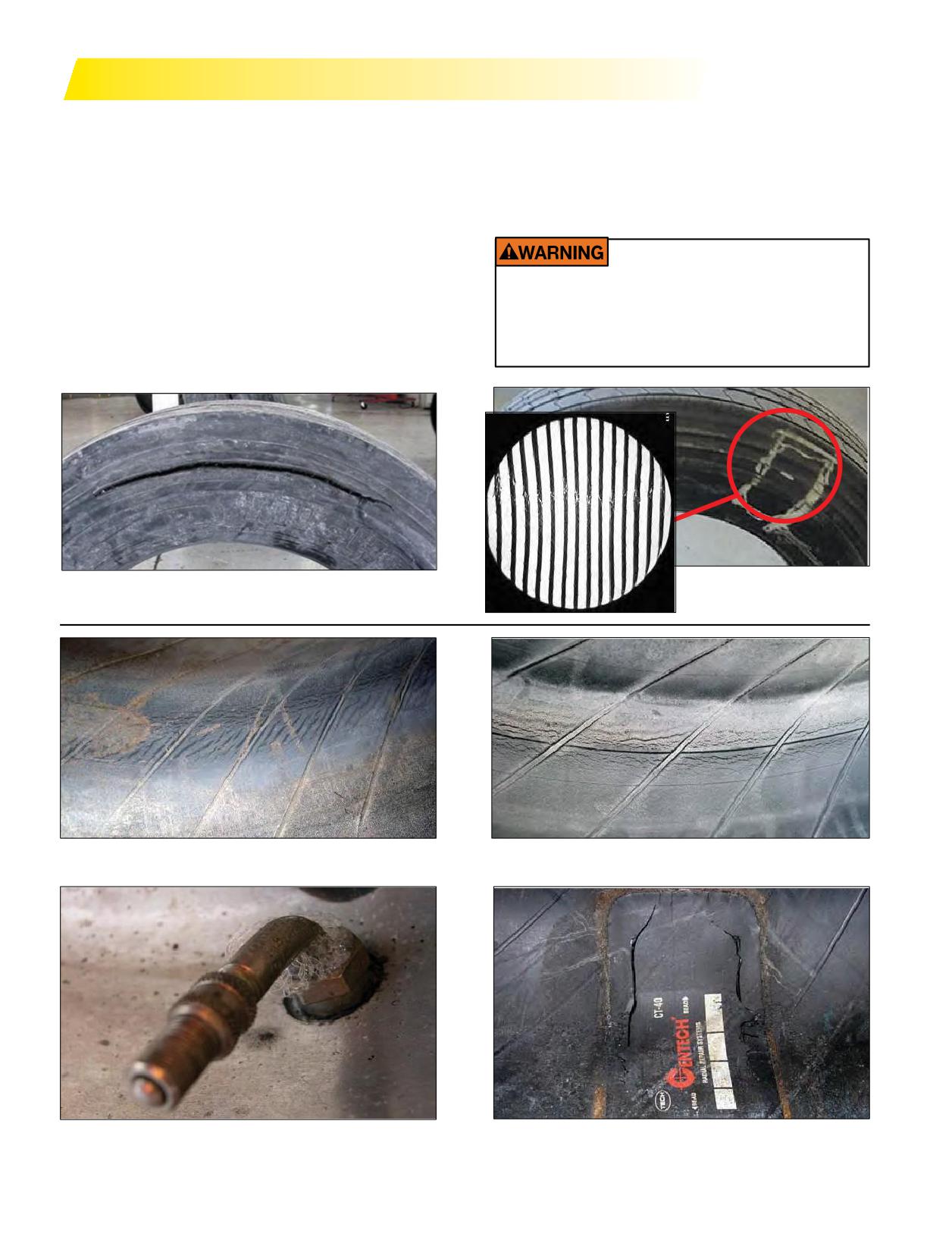
RUN-FLAT
RUN-FLAT AND ZIPPER RUPTURES
Occasionally, a tire will be flat when it arrives at the
repair facility and there will be no external signs of a
Run-flat: Any tire thatis known or suspected to have run
rupture. Note the X-ray photo below on the right reveals
at less than 80% of normal recommended operating tire
the broken casing ply cords.
pressure.
If re-inflated, this tire will experience a rapid loss of tire
Normal Operating Pressure: The cold infl
pressure
pressure with explosive force.
required to support a given load as recommended by the
tire manufacturer’s data book.
Zipper Rupture: This condition is a circumferential
Tires operated below the recommended tire
pressure (run flat) are susceptible to zipper
rupture in the flex zone of the sidewall. This damage is
ruptures, particularly during the re-inflation
associated with underinflation and/or overloading. Any
process. Zipper ruptures pose a serious risk to
moisture that is permitted to reach ply cords will cause
personnel and must be well understood.
corrosion, which can also result in a zipper rupture.
Circumferential Rupture of Casing Ply or “Zipper
X-ray Photo of Broken
Rupture”
Cords on Unruptured Casing
EFFECT: Inner Liner Marbling - Creasing
EFFECT: Inner Liner Cracking
CAUSE: Underinflation
CAUSE: Underinflation
EFFECT: Leaking Valve, Grommet, or Wheel
EFFECT: Crack in the Repair Unit
CAUSE: Improper Installation - Torque, Lubrication,
CAUSE: Improper Repair or Improper Repair Procedures
Corrosion
146 Section Nine: Tire Damage
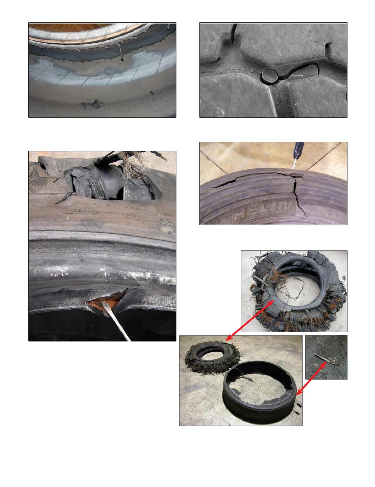
EFFECT: Discoloration, Blistering, and/or Separations of
EFFECT: Crack Around Nail Hole Plug
the Inner Liner
CAUSE: Improper Repair or Improper Repair Procedures
CAUSE: Continued Operation After Loss of Tire
Pressure
EFFECT: Crown/Sidewall Injury Resulting in Tire Pressure
Loss
CAUSE: Nail Hole Bolt/ Debris Penetrating the Liner
EFFECT: Sidewall Separation Due to Air Infiltration
Resulting from Bead Damage
CAUSE: Due to Mount/Dismount
EFFECT: Run-flat
CAUSE: Crown Perforation/Penetration
Section Nine: Tire Damage
147
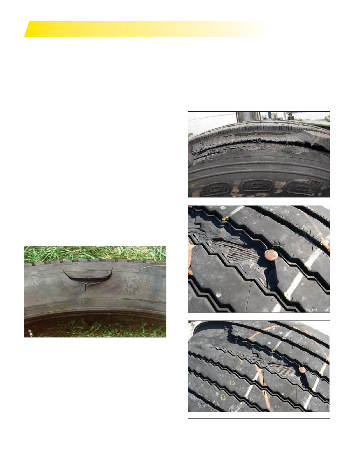
AIR INFILTRATION
Air infiltration is an “inside-out” damage. The air inside the
Just as the MICHELIN® X One® tire reacts differently to
tire is much higher (80-120 psi) than atmospheric pressure.
pressure settings, it also reacts differently to air infiltration.
Modern tubeless tires have a major advantage over a tube-
The usual effect of air infiltration on an MICHELIN® X One®
type tire. When a tube-type tire is punctured, it only takes
tire can be seen between the top or protector ply and the
seconds to become flat. A tubeless tire may take weeks or
tread rubber. Air infiltration always results in removing the
monthsfortheair to escape - thisis because theinner-liner
tire from service (dual or wide single); however, not having
(airtight lining) is integral to the tire. One issue with tubeless
belt separation or large sidewall ruptures could prevent rapid
tires is that even though theymay take a long time to go flat,
tire pressure loss events.
the air is still trying to get out. As the high pressure air makes
its way back through the puncture channel, it can separate
products within the tire.
The cause of air infiltration can be from:
• nail or other puncture
• objects left in the tire
• bad repair
• bead damage from mounting/dismounting
• anything that has caused the innerliner to become damaged
Adual tire can show this effect on the upper sidewall, bead
area, or between crown belts. Nine times out of ten, though,
it will be in the upper sidewall and manifest itself as a flap or
“smiley face.”
Amoresevere form of air infiltration on dual tires results in
belt separation and subsequent rapid tire pressure loss.
148 Section Nine: Tire Damage
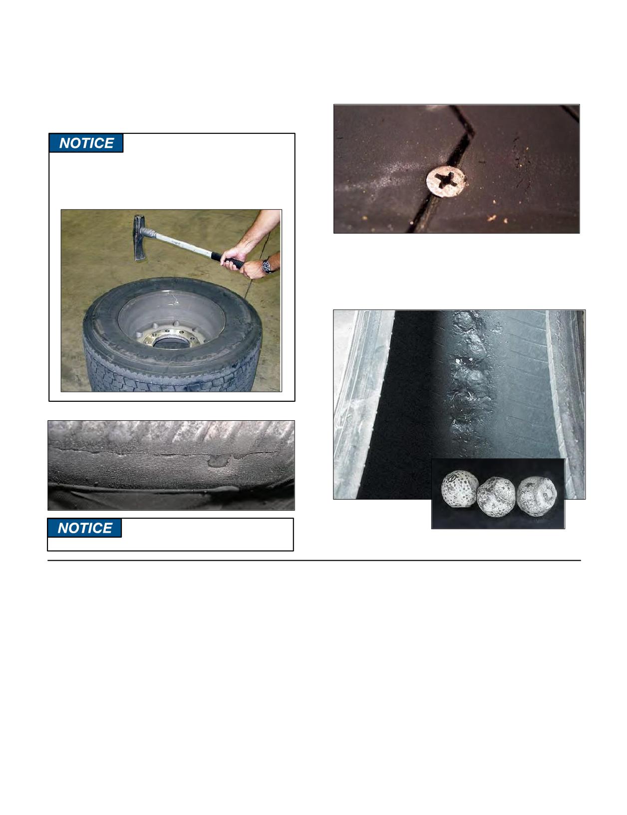
AIR INFILTRATIONS ARE AVOIDABLE.
Never use a duckbill hammer to mount tubeless truck
Remove and repair nails, screws, and other penetrations
tires, as this is the number one cause of bead damages.
promptly, BEFORE they can cause air infiltration.
Use proper repair techniques, and inspect all repairs
prior to returning tire to service.
Do not use hammers of any type. Striking a
wheel assembly with a hammer can damage
both the tire and the wheel and is a direct
OSHA* violation.
NEVER leave service items inside the tire like repair parts,
valves, caps, etc. NEVER intentionally place items like golf
ballsinside the tire to “act”asabalancing agent, as this can
lead to inner-liner damage.
* Occupational Safety and Health Administration
Any object that cuts the inner-liner
can lead to air infiltration!
THE USE OF INTERNAL BALANCING
and/ or coolant manufacturer as being safe for use in
tires. Water/moisture content testing should be included
MATERIALS AND/OR COOLANTS IN
in the certification process. Any product with a water or
MICHELIN® TRUCK TIRES
moisture content greater than 3% as measured by the Karl
The use of internal balancing materials and/or
Fisher Method (ASTM D6304) will automatically void any
coolants (such as powders, liquids, gels and/or beads) in
mileage, number of retreads and/or time warranty.
MICHELIN® Truck Tires does not automatically affect the
In addition to the forgoing, please refer to the
tire warranty unless the internal balancing material and/
MICHELIN® Truck Tire Operator’s Manual and Limited
or coolant has a high water/moisture content or that it is
Warranty (MWE40021) for a general discussion of what is
determined that the internal balancing material and/or
and is not covered by the warranty.
coolant has adversely affected the inner liner, casing plies,
NOTE: Please consult Michelin prior to using internal
or the performance of the tires. Prior to using any type
®
balancing materials and/or coolants in any MICHELIN
of internal balancing material and/ or coolant, Michelin
tires that have sensors in them. The internal balancing
strongly recommends that the customer make sure the
materials and/or coolants may adversely affect the
internal balancing material and/ or coolant has been
performance of the sensors.
tested and certified by the internal balancing material
Section Nine: Tire Damage
149
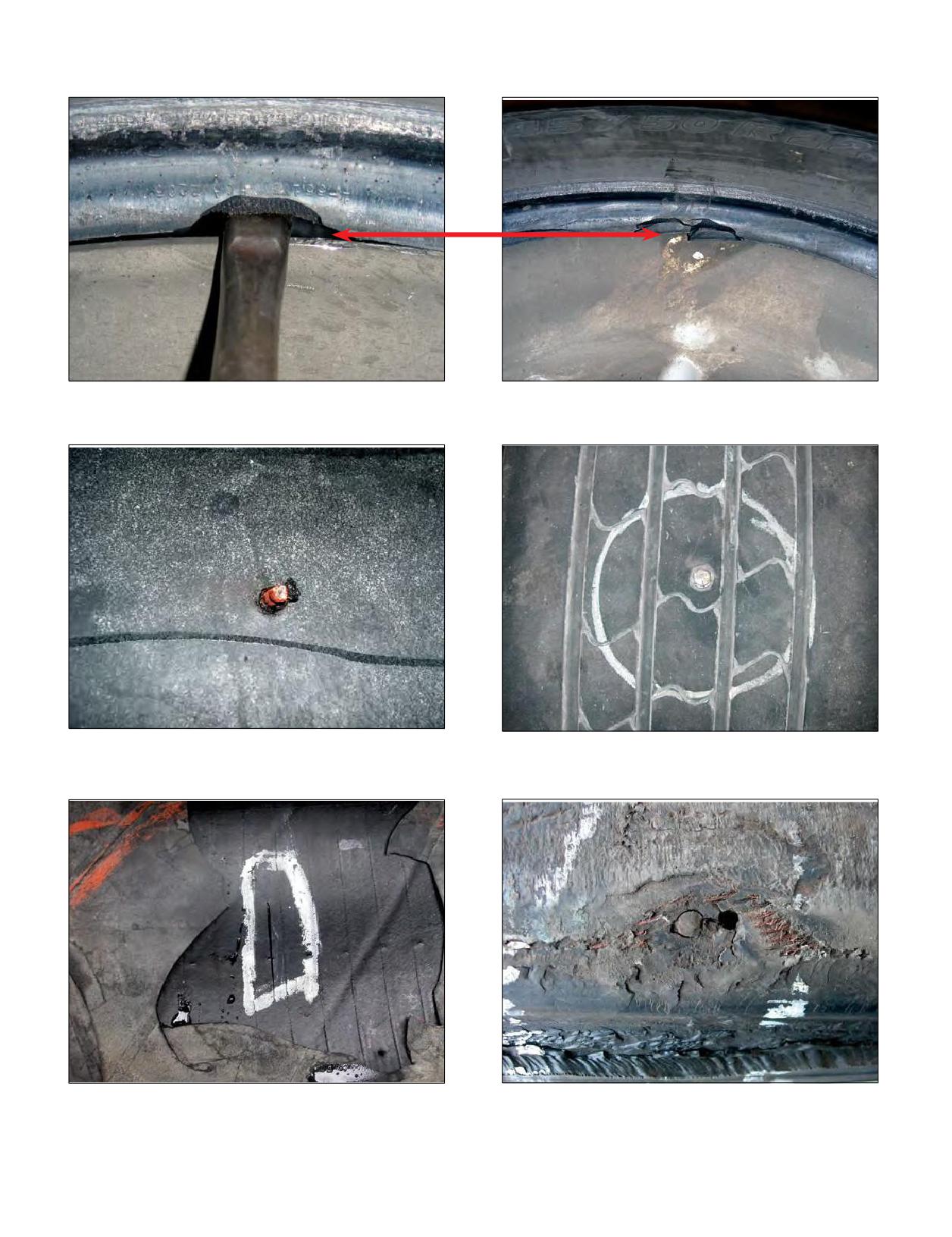
Any damage that opens the inner liner and allows air under pressure to migrate within the steel and rubber products.
EFFECT: Bead Area or Inner Liner Damage
CAUSE: Improper Demounting Procedure,
Lack of Lubricant
EFFECT: Premature Failure of Repair
EFFECT: Object that Penetrates Into the Tire and
CAUSE: Object that Penetrates Into the Tire and
Through the Inner Liner
Through the Inner Liner
CAUSE: Nail, Bolt, Screw, etc.
EFFECT: Radial Liner Split
EFFECT: Missed Nail Hole
CAUSE: Due to Impact
CAUSE: Repaired from the Outside Resulting in Missed
Damage
150 Section Nine: Tire Damage
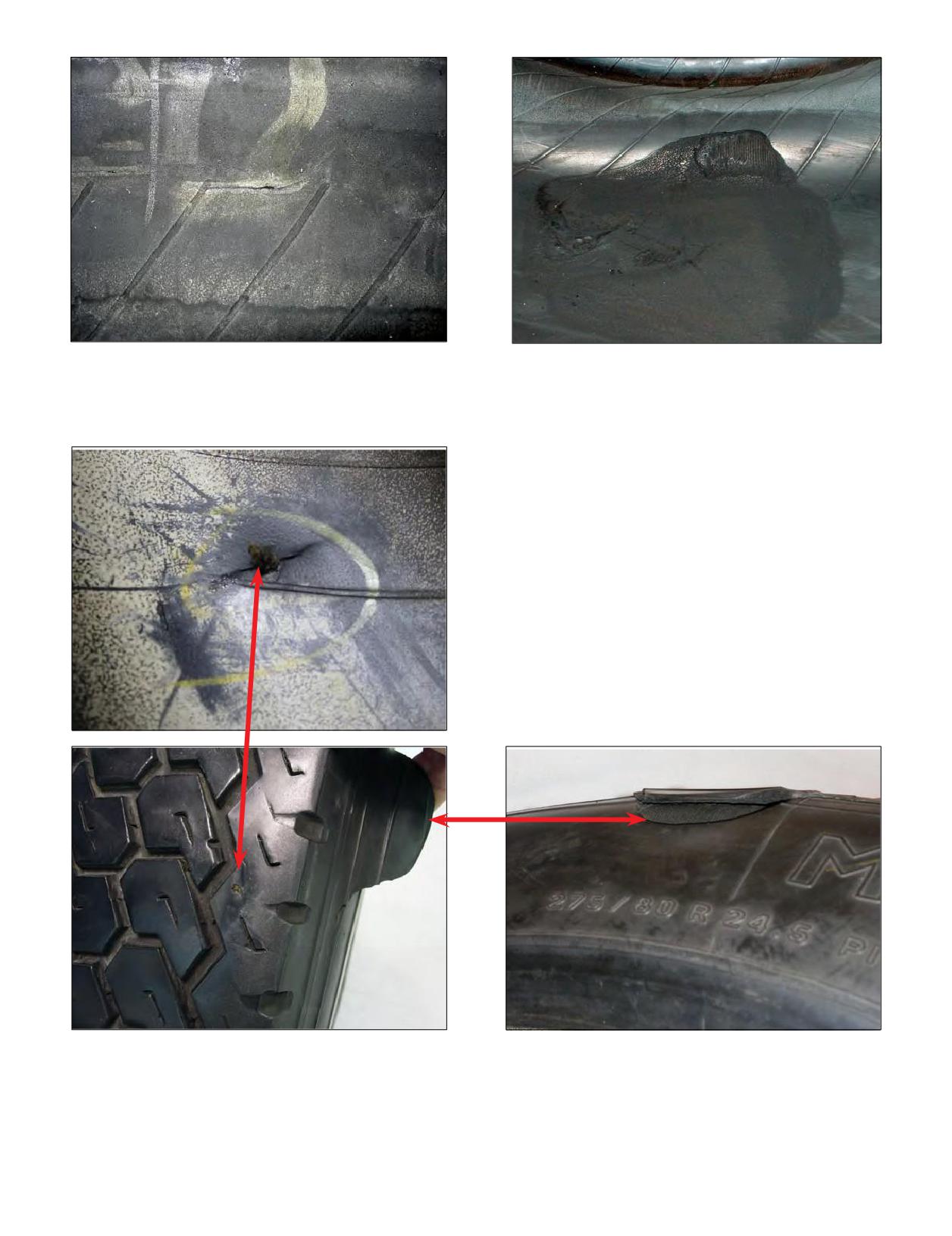
EFFECT: Inner Liner Cut
EFFECT: Inner Liner Burn
CAUSE: Shipping or Mounting Damage
CAUSE: Electrical Discharge Damage
EFFECT: Sidewall Separation Due to Air Infiltration
CAUSE: Improper Repair
Section Nine: Tire Damage
151
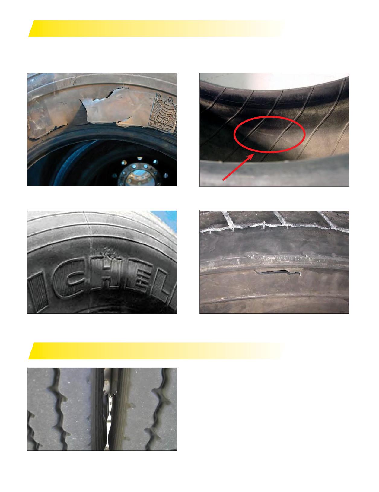
PINCH SHOCK
Crown/sidewall impact, crushing the tire and creating internal damage to the rubber products due to severe crushing.
• Impact with a curb, pothole, road debris, etc.
• Severe impact with any blunt object
EFFECT: External Rubber Damage
EFFECT: Internal Creasing
CAUSE: Severe Impact
CAUSE: Severe Impact
EFFECT: Small Bulge
Sidewall Rupture Shock
CAUSE Impact With a Curb, Pothole, Road Debris, etc.
MINIMUM DUAL SPACING - KISSING DUALS
EFFECT: Friction Severely Weakens the Casing
CAUSE: Improper Minimum Dual Spacing
152 Section Nine: Tire Damage
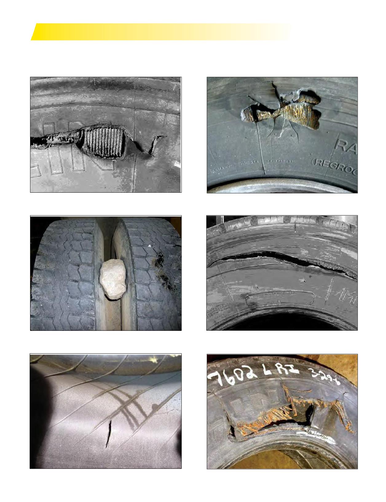
IMPACT DAMAGE
• With or without a rupture - zipper
• Crown, shoulder, or sidewall
• Impact with a sharp cutting object (A rupture usually indicates a rather severe impact.)
EFFECT: Break in Tire Interior Surface, Pulled or Loose
EFFECT: Impact Damage
Cords
CAUSE: Severe Impact With Any Blunt Object
CAUSE: Severe Impact With Any Blunt Object
EFFECT: Sidewall Damage
EFFECT: Impact Damage
CAUSE: Object Wedged Between Dual Assembly
CAUSE: Sidewall Rupture from Shock
EFFECT: Inner Liner Split
EFFECT: Impact Damage
CAUSE: Sidewall Impact
CAUSE: Sidewall Rupture from Shock
Section Nine: Tire Damage
153
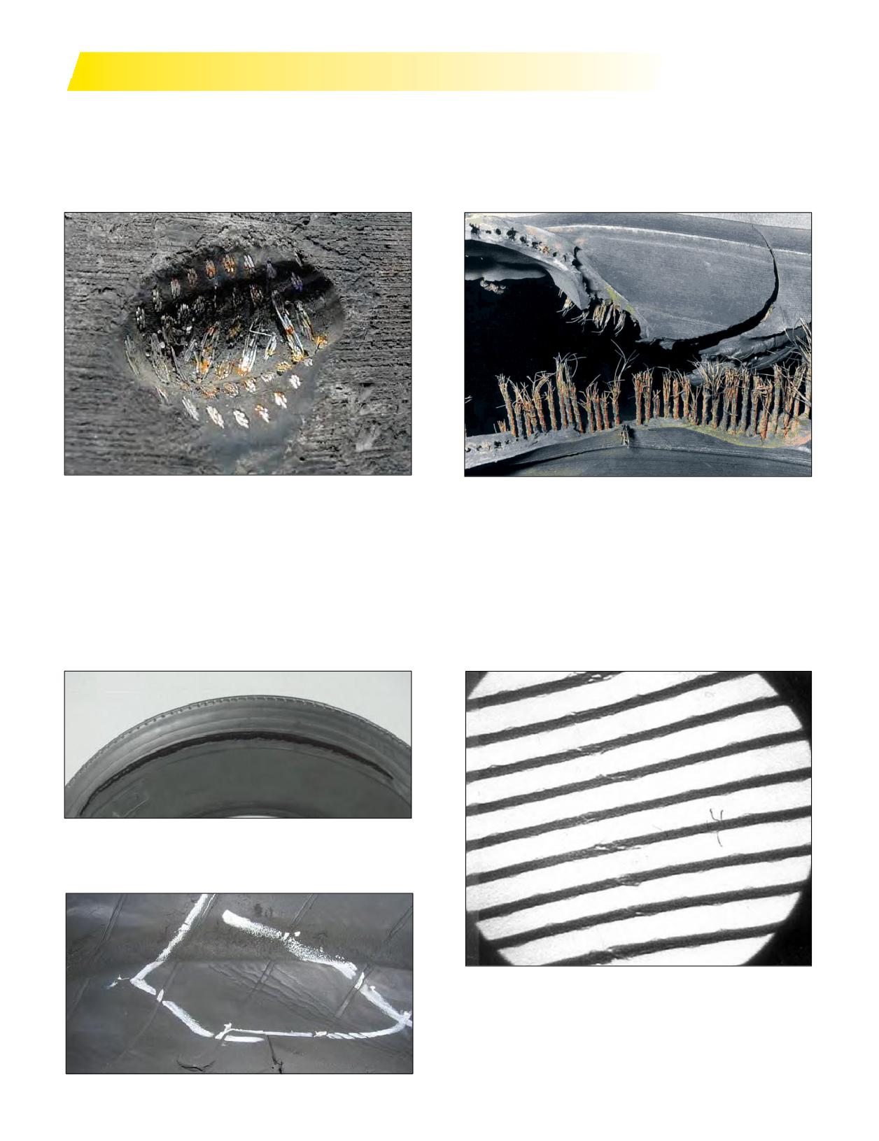
FATIGUE RELATED DAMAGE
• With or without a rupture - zipper*
• Any damage that will allow the casing to oxidize or the casing plies to weaken or break
• Run-flat tires (mainly dual positions)
• Impacts to steel (not filled or repaired)
• Improper repair or improper repair procedures (premature failure of repair)
EFFECT: Exposed Steel Cord
EFFECT: Any Damage That Will Allow the Casing to
CAUSE: Detachment of Repair Product
Oxidize
CAUSE: Moisture
*ZIPPER
A fatigue related damage, with or without a rupture, occurs in the sidewall flex area of steel radial light and medium truck
tires when it is subjected to excessive flexing or heat. This zipper rupture is a spontaneous burst of compressed air and the
resulting rupture can range in length anywhere from 12 inches to 3 feet circumferentially around the tire. This is caused by
the damage and weakening of the radial steel cables as a result of underinflation and the tire running flat. Eventually, the
pressure becomes too great for the cables to hold, and the area ruptures with tremendous force.
EFFECT: Zipper Rupture
CAUSE: Damage/Weakening of Radial Steel Cables as
a Result of Underinflation and Running the
Tire Flat
MRT X-Ray Image of Fatigue-Related Damage Without a
Rupture
154 Section Nine: Tire Damage
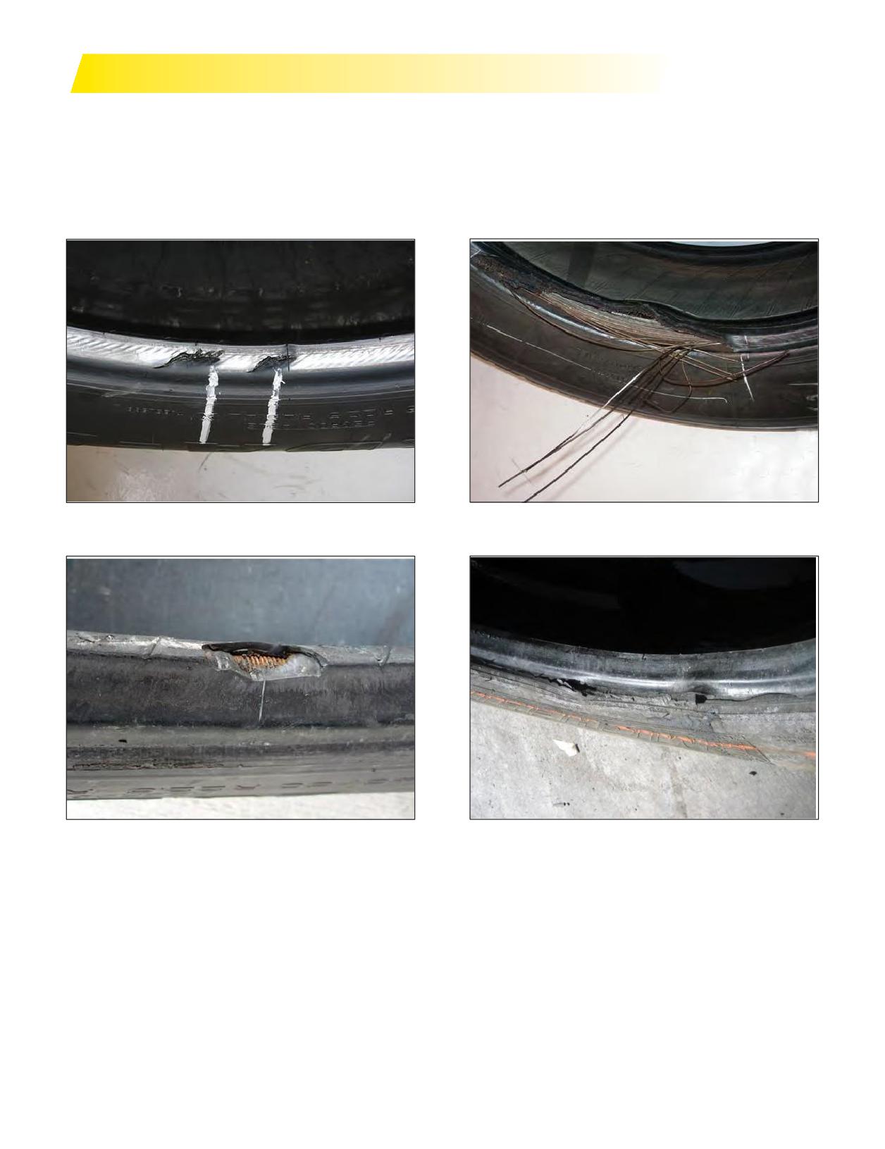
BEAD DAMAGE
Bead turning, cracking/splitting, unwrapping.
• Heavy brake heat generating operations
• Mechanical brake system out of specification
• Incorrect wheel width
• Excessive flex from overload/underinflation
• Mounting/Demounting (insufficient lubrication, improper tool use, aggravated by heat (beads become brittle))
EFFECT: Heating and Deformation of the Bead Rubber
EFFECT: Bead Turning, Cracking/Splitting, Unwrapping
CAUSE: Excessive Heat
From Heat
CAUSE: Excessive Heat
EFFECT: Bead Tearing From Mounting/Demounting
EFFECT: Bead Turning, Cracking/Splitting, Unwrapping
CAUSE: Insufficient Lubrication, Improper Tools
From Heat
CAUSE: Excessive Heat
Section Nine: Tire Damage
155
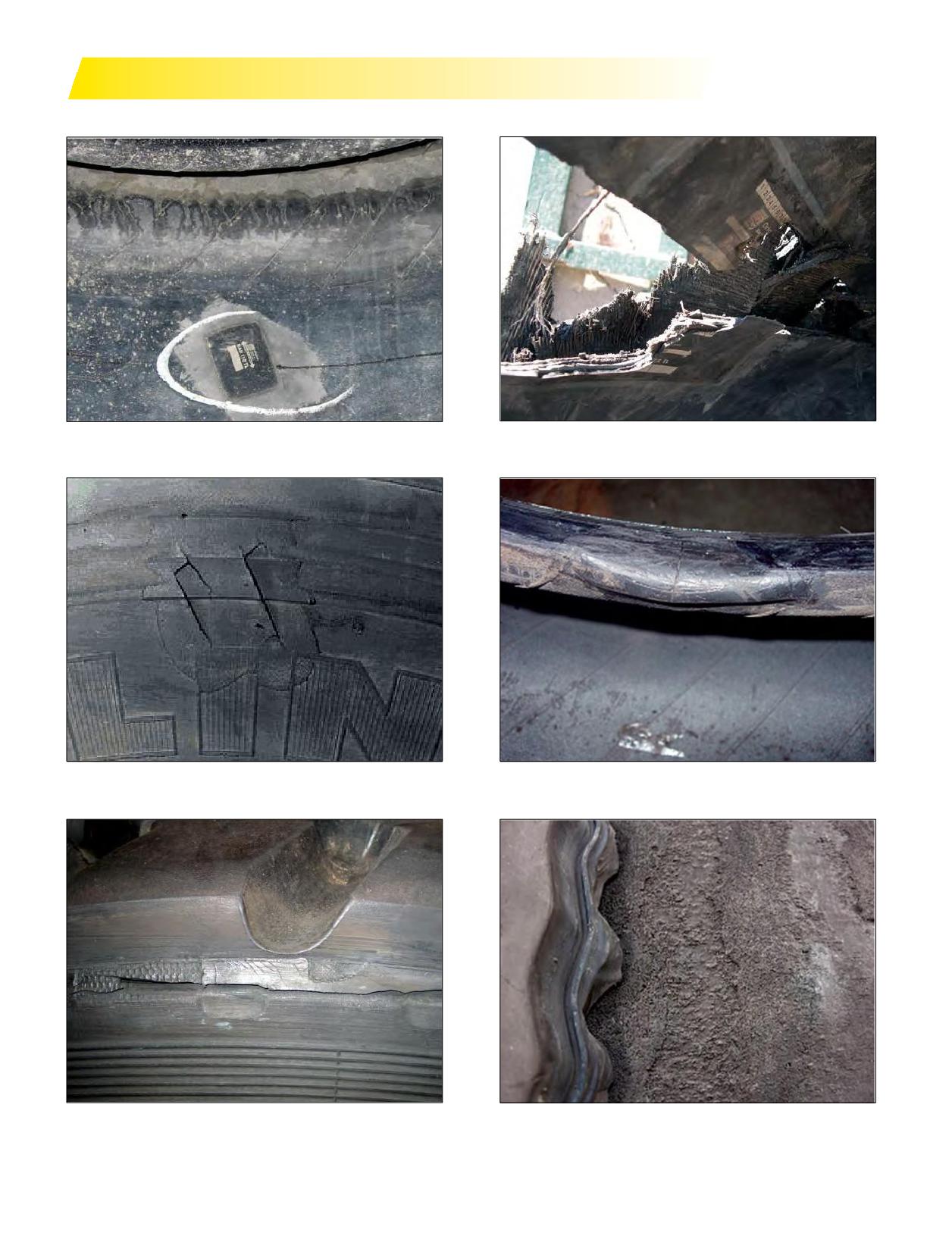
ADDITIONAL CAUSES: REPAIRS & RETREADING CONDITIONS
Improperly Aligned Repair (Note that the arrows on
Rupture on Improperly Aligned Repair (Note that the
the patch do not point toward the beads.)
arrows on the patch do not point toward the beads.)
Bad Sidewall Spot Repair
Bad Bead Repair
Tread Edge Lifting
Porosity
156 Section Nine: Tire Damage
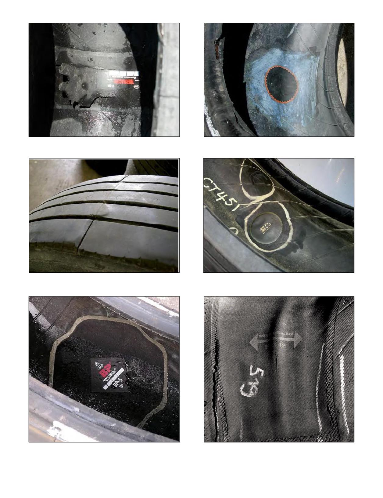
EFFECT: Improper Repair or Improper Repair Procedures
Improper Repair, Tube Repair Patch In Radial Tire, and
CAUSE: Premature Failure of Repair
Bead Damage from Demounting
Open Splice Joint
EFFECT: Improper/Incomplete Repair
CAUSE: Internal Sidewall Damage from Penetrating
Object Not Repaired
Improper Repair, Bias Ply Patch In a Radial Tire,
Bridged Repair (Rupture, Split, or Cracking of the
Note Also the Misalignment
Repair Material)
Section Nine: Tire Damage
157

SCRAP INSPECTION FORM
EXAMPLE
Fleet:
Date:
MFR. DOT
TREAD
RETREAD INFO
CONDITIONS
SIZE
TYPE
MFR.
PL
WK
YR
DEPTH
#
WHO
WK/YR
EFFECT
CAUSE
COMMENT
275/80R22.5
XDA-HT
MX
B6
29
92
07/32
2
RRL
148
RF
SP
275/80R22.5
XT-1
MX
B6
4
98
05/32
0
IM
SI
275/80R22.5
XT-1
MX
B6
1
98
08/32
0
PS
CD
275/80R22.5
XDN2
MX
M5
35
95
07/32
1
RRL
18
ZP
IR
Fleet:
Date:
MFR. DOT
TREAD
RETREAD INFO
CONDITIONS
SIZE
TYPE
MFR.
PL
WK
YR
DEPTH
#
WHO
WK/YR
EFFECT
CAUSE
COMMENT
Tire Condition Index: Effect and Cause
158 Section Nine: Tire Damage
SECTION TEN
Appendix
Section Ten
Appendix
159-187
GENERAL INFORMATION
160-163
Units of Measurement
Pressure Unit Conversion Table
Load Range/Ply Rating
Approximate Weight of Materials
Load Index
Conversion Table (Standard - Metric - Degrees)
Speed Symbol
RUNOUT TOLERANCES
164
FRONT END ALIGNMENT
164
Toe
Camber
Caster
AXLE ALIGNMENT
165
Tandem Scrub Angle or Skew
Thrust Angle Deviation
Steering Axle Offset
Drive Axle Offset
Steering Axle Skew
ALIGNMENT - FIELD METHOD
166-167
CASING MANAGEMENT
168-169
COLD CLIMATE PRESSURE CORRECTION DATA
169
COST ANALYSIS
170
FUEL SAVINGS
171
MOUNTING PROCEDURES FOR 16.00R20 AND 24R21
172
TIRE REVOLUTIONS PER MILE CALCULATION
173
OUT-OF-SERVICE CONDITIONS
174-175
RUNOUT AND VIBRATION DIAGNOSIS
176-178
SERVICING MULTI-PIECE AND SINGLE PIECE
RIM/WHEELS (OSHA 1910.177)
179-181
REGROOVING
182-183
TRANSIT APPLICATIONS IN URBAN CONDITIONS
184
THE CRITICAL 6 - FACTORS THAT COST FLEETS MONEY
185
PUBLICATIONS, VIDEOS, AND WEBSITES
186-187
INDEX
188
Section Ten: Appendix
159

GENERAL INFORMATION
UNITS OF MEASUREMENT
PRESSURE UNIT CONVERSION TABLE
Quantity
S.I. Units
Other Units
kPa
bar
lb/in2*
kg/cm2*
100
1.0
15
1.0
1 inch (“) = 0.0254 m or 25.4 mm
m
150
1.5
22
1.5
Length
1 mile = 1609 m (1.609 km)
(meter)
1 kilometer = 0.621 mile
200
2.0
29
2.0
250
2.5
36
2.5
1 pound (lb) = 0.4536 kg
300
3.0
44
3.1
kg
Mass
(kilogram)
1 kilogram (kg) = 2.205 lbs.
350
3.5
51
3.6
400
4.0
58
4.1
1 bar* = 100 kPa
450
4.5
65
4.6
kPa
1 psi = 6.895 kPa
Pressure
(Pascal)
1 pound per square inch
500
5.0
73
5.1
1 kg/cm2 - 98.066 kPa
550
5.5
80
5.6
1 kilometer per hour (kph)* =
600
6.0
87
6.1
m/s
0.27778 m/s
Speed
(meter per
650
6.5
94
6.6
1 mile per hour (mph) =
second)
0.4470 m/s (or 1.60935 kph)
700
7.0
102
7.1
* Non S.I. unit to be retained for use in specialized fields.
750
7.5
109
7.7
800
8.0
116
8.2
850
8.5
123
8.7
900
9.0
131
9.2
950
9.5
138
9.7
LOAD RANGE/PLY RATING
1000
10.0
145
10.2
B
-
4
1050
10.5
152
10.7
C
-
6
* Values in psi and kg/cm2 rounded to the nearest practical unit.
D -
8
E
- 10
F
- 12
G - 14
H - 16
J
- 18
L
- 20
M - 22
160 Section Ten: Appendix

APPROXIMATE WEIGHT OF MATERIALS
Most materials and commodities vary in weight - the following weights should be used only for approximation
purposes. Exact weights should be obtained from local sources when making recommendations for truck or
tractor-trailer equipment.
Lbs. per Cu. Ft.
No. of Pounds
Per:
Beans, dry
60
Bushel
Cement, Portland
-
94
Bag
Clay and Gravel, dry
100
2700
Cu. Yd.
Clay and Gravel, wet
65
1755
Cu. Yd.
Coal, Hard or Anthracite, broken
52-57
1400-1540
Cu. Yd.
Coal, Soft or Bituminous, solid
79-84
2134-2270
Cu. Yd.
Concrete
120-155
3200-4185
Cu. Yd.
Corn, in ear
-
70
Bushel
Corn, shelled
--
56
Bushel
Corn Syrup
86
11.5
Gallon
Crude Oil
52
700
100 Gal.
Fuel Oil
52-74
695-795
100 Gal.
Gasoline
45
600
100 Gal.
Gravel
100-120
2700-3240
Cu. Yd.
Gravel and Sand, dry, loose
90-100
2430-2862
Cu. Yd.
Gravel and Sand, dry, packed
110
2970
Cu. Yd.
Gravel and Sand, wet
120
3240
Cu. Yd.
Milk
--
845-865
100 Gal.
Paper, average weight
58
Oats
--
32
Bushel
Potatoes, White or Irish
-
60
Bushel
Petroleum
-
800
100 Gal.
Sand, dry, loose
90-106
2430-2860
Cu. Yd.
Sand, moist, loose
120
3240
Cu. Yd.
Soy Beans
--
60
Bushel
Water
62.4
835
100 Gal.
Wheat
--
60
Bushel
Section Ten: Appendix
161

LOAD INDEX
TheISO*LOADINDEXisa numericalcodeassociatedwiththemaximumload atirecancarryat the speed
indicated by its SPEED** SYMBOL under service conditions specified by the tire manufacturer. (1 kg = 2.205 lbs.)
Load Index
kg
lbs.
Load Index
kg
lbs.
Load Index
kg
lbs.
100
800
1,765
134
2,120
4,675
168
5,600
12,300
101
825
1,820
135
2,180
4,805
169
5,800
12,800
102
850
1,875
136
2,240
4,940
170
6,000
13,200
103
875
1,930
137
2,300
5,070
171
6,150
13,600
104
900
1,985
138
2,360
5,205
172
6,300
13,900
105
925
2,040
139
2,430
5,355
173
6,500
14,300
106
950
2,095
140
2,500
5,510
174
6,700
14,800
107
975
2,150
141
2,575
5,675
175
6,900
15,200
108
1,000
2,205
142
2,650
5,840
176
7,100
15,700
109
1,030
2,270
143
2,725
6,005
177
7,300
16,100
110
1,060
2,335
144
2,800
6,175
178
7,500
16,500
111
1,090
2,405
145
2,900
6,395
179
7,750
17,100
112
1,120
2470
146
3,000
6,610
180
8,000
17,600
113
1,150
2,535
147
3,075
6,780
181
8,250
18,195
114
1,180
2,600
148
3,150
6,940
182
8,500
18,745
115
1,215
2,680
149
3,250
7,160
183
8,750
19,295
116
1,250
2,755
150
3,350
7,390
184
9,000
19,845
117
1,285
2,835
151
3,450
7,610
185
9,250
20,400
118
1,320
2,910
152
3,550
7,830
186
9,500
21,000
119
1,360
3,000
153
3,650
8,050
187
9,750
21,500
120
1,400
3,085
154
3,750
8,270
188
10,000
22,050
121
1,450
3,195
155
3,875
8,540
189
10,300
22,720
122
1,500
3,305
156
4,000
8,820
190
10,600
23,400
123
1,550
3,415
157
4,125
9,090
191
10,900
24,040
124
1,600
3,525
158
4,250
9,370
192
11,200
24,700
125
1,650
3,640
159
4,375
9,650
193
11,500
25,360
126
1,700
3,750
160
4,500
9,920
194
11,800
26,020
127
1,750
3,860
161
4,625
10,200
195
12,150
26,800
128
1,800
3,970
162
4,750
10,500
196
12,500
27,565
129
1,850
4,080
163
4,875
10,700
197
12,850
28,355
130
1,900
4,190
164
5,000
11,000
198
13,200
29,110
131
1,950
4,300
165
5,150
11,400
199
13,600
30,000
132
2,000
4,410
166
5,300
11,700
200
14,000
30,870
133
2,060
4,540
167
5,450
12,000
201
14,500
31,980
* International Standardization Organization
** Exceeding the legal speed limit is neither recommended nor endorsed.
162 Section Ten: Appendix

CONVERSION TABLE
SPEED SYMBOL**
The ISO* SPEED SYMBOL indicates the
Size: 275/80R22.5
speed at which the tire can carry a load
Overall Diameter: 40.1
corresponding to its Load Index under
service conditions specified by the tire
Inches
Inches
Millimeters
Degrees
(decimal)
(fraction)
manufacturer.
0.03125
1⁄32
0.8
0.04
Speed**
Speed Symbol
0.06250
1⁄16
1.6
0.09
kph
mph
0.09375
3⁄32
2.4
0.13
A1
5
2.5
0.12500
1 ⁄ 8
3.2
0.18
A2
10
5
0.15625
5⁄32
4.0
0.22
A3
15
10
0.18750
3⁄16
4.8
0.27
A4
20
12.5
0.21875
7⁄32
5.6
0.31
A5
25
15
0.25000
1 ⁄ 4
6.4
0.36
A6
30
20
0.28125
9⁄32
7.1
0.40
A7
35
22.5
0.31250
5⁄16
7.9
0.45
A8
40
25
0.34375
11⁄32
8.7
0.49
B
50
30
0.37500
3⁄
8
9.5
0.54
C
60
35
0.40625
13⁄
32
10.3
0.58
D
65
40
0.43750
7⁄16
11.1
0.63
E
70
43
0.46875
15⁄ 32
11.9
0.67
F
80
50
0.50000
1 ⁄ 2
12.7
0.71
G
90
56
J
100
62
K
110
68
L
120
75
M
130
81
N
140
87
* International Standardization Organization
** Exceeding the legal speed limit is neither
recommended nor endorsed.
Section Ten: Appendix
163
RUNOUT TOLERANCES (LATERAL AND RADIAL)
TMC Tire / Wheel Assembly Specifications
TMC Rim/Wheel Specifications
0.080”
0.070” (STEEL)
0.030” (ALUMINUM)
Note: Vibration can be felt on some vehicles with values lower than the stated specifications.
For best results, maintain radial and lateral runout less than .060” for the Tire/Wheel Assembly when possible.
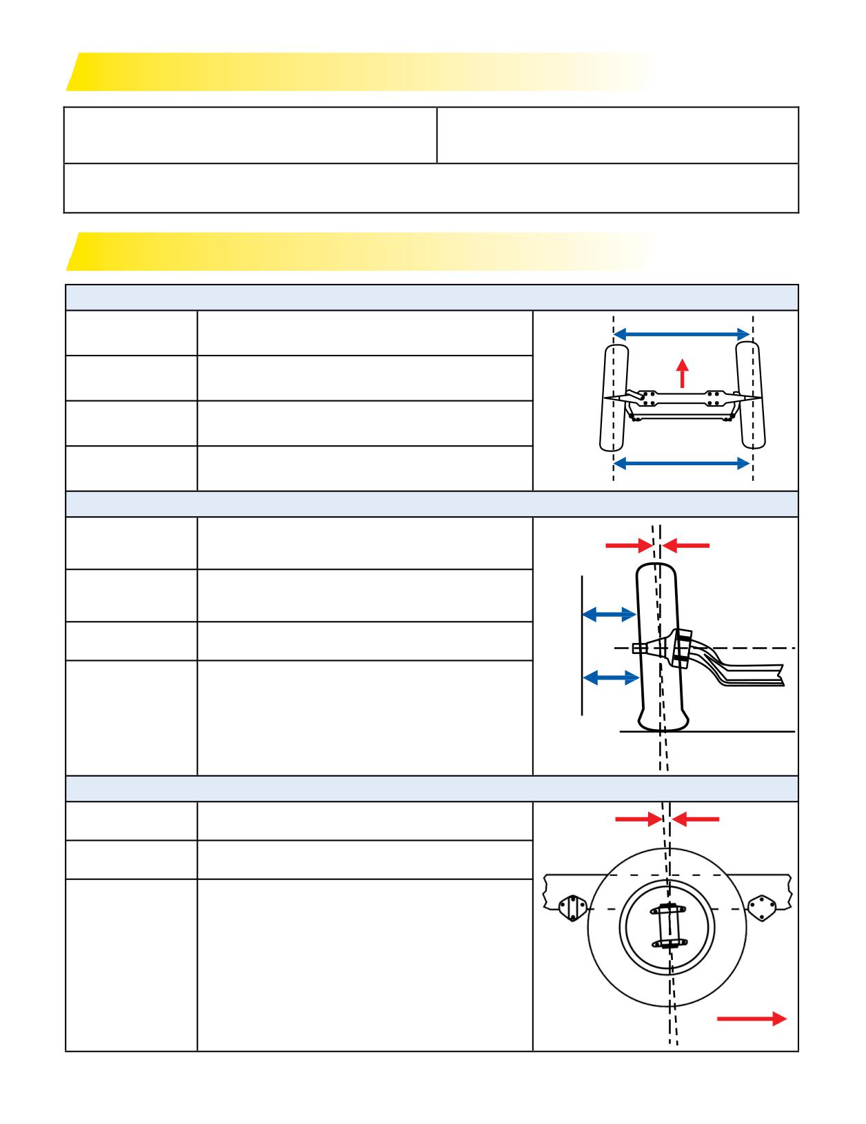
FRONT END ALIGNMENT
TOE
I
Target:
Steer: +1/16” (+1.5 mm)
Target:
Drive & Trailer: 0
Measurement:
J - I
Symptoms:
Feathered Wear
J
CAMBER
Steer Loaded: 0° to 1/4°
Target:
POSITIVE
or 0 to 2.5 mm
CAMBER
Drive & Trailer: ±1/4°
Target:
or ±0 to 2.5 mm
L
Measurement:
K - L
K
Shoulder Wear
Pulling (Large variation left/right)
Symptoms:
Pulls to side with most positive camber
CASTER
Target:
Steer Only: Left +3.5° Right +4.0°
POSITIVE
CASTER
Measurement:
Alignment Machine
Wander (Caster too low)
Slow or no return to center
Shimmy or harsh ride (Caster too high)
Rapid return to center
Symptoms:
Pull to side with least positive caster
These settings allow for ease of
FRONT
steering and assist in counteracting
road crown
164 Section Ten: Appendix
AXLE ALIGNMENT
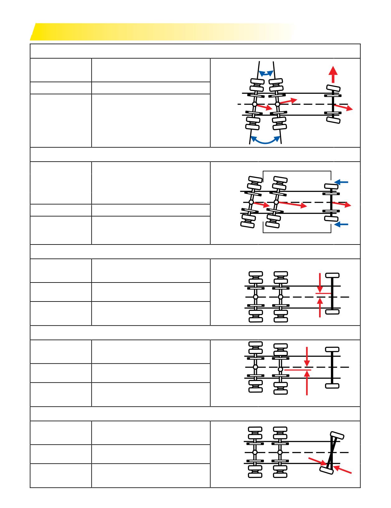
TANDEM SCRUB ANGLE OR SKEW
Target:
0
A
Tolerance:
±1/8” or ±3 mm
THRUST
Measurement:
A ± B
ANGLE A
THRUST
Steer tire shoulder wear
ANGLE
B
and/or feathered wear
Symptoms:
Excessive drive tire wear
Pulling, driver counter steers
B
Tandem Hop
THRUST ANGLE DEVIATION
Target:
0
Tolerance:
Based on wheel base:
THRUST
C
ANGLE A
15 mm < 150”, 20 mm
150-200”, 25 mm > 200”
THRUST
ANGLE
B
Measurement:
C ± D
Steer tire shoulder wear
D
Symptoms:
Pulling slightly to significant
STEERING AXLE OFFSET
STEERING AXLE OFFSET
Target:
0
Tolerance:
±3/16” or ±5 mm
E
Measurement:
(E ± F)/2
Steer tire shoulder wear
Symptoms:
F
Pulling slightly
DRIVE AXLE OFFSET
Target:
0
G
G
Tolerance:
±3/16” or ±5 mm
Measurement:
(G ± H)/2
H
H
Symptoms:
Pulling slightly
DRIVE AXLE OFFSET
STEERING AXLE SKEW
Target:
0
Tolerance:
±3/16” or ±5 mm
Measurement:
Alignment Machine
Pulling. Steer tire wear could
Symptoms:
be significant
STEERING AXLE SKEW
Section Ten: Appendix
165
ALIGNMENT - FIELD METHOD
ATTACC PLUS SYSTEM (Axle, Thrust, Toe,
3. Measurefor steering axle offset from the frame rail to the
Ackerman, Camber, Caster Parts, Labor, User Saves)
vertical center line on the tire on both sides. Tolerance is ±
• Simple vehicle measurement system
3/16”or5mmfrom centerline ofvehicle.
• Quick, low cost, yet effective method
4. Steering Stops: Ensure they are in place on left and right
• Determine if poor alignment conditions exist
sides, and measure length. Stops control the angle of the
• Minimum tools required
turn and may be a consideration if abnormal steer tire wear
For more information about ATTACC PLUS refer to
is present.
Michelin Vehicle Alignment: ATTACC Plus Video at
5. Checkfront end componentsandtoe byjacking upfront
end after placing wheel chocks on the rear tires. Place the
videos/#/maintenance-and-training
floor jack under the axle for support, use the T-45A tire
iron by inserting into the wheel assembly at the 6 o’clock
position and place your otherhandat the 12o’clock
SET-UP INSTRUCTION PROCEDURES
position. With a rocking type motion try to move the tire
TOOLS:
assembly up with the lower bar and out towards you with
• Chalk Line (no chalk)
• Metric Tape Measure
your left hand. If play is felt, it is probably the result of loose
• 2 Cans of White Spray Paint
• 1 pair of Jack Stands
wheel bearings or worn kingpin bushings. If you observe
• 2 Large Heavy Duty Plastic Bags
• Toe-Scribe
the brakechambermoving,itcanbeisolatedto the kingpin
• Vehicle Jack (10 Tons)
• Flashlight
bushing. If it does notmove, it is likely the wheel bearings.
• Line Level and Wheel Chocks
• 1 T-45A Tire Iron
With your hands placedat the 3 o’clock and at the
SURFACE: Inspection site should be fairly level; use Line
9 o’clock positions on the tire, try to move the tire in a rapid
Level if necessary to determine slope.
“left turn - right turn” type of motion. Feel and listen for
STEER/DRIVE TIRES: Note tread design, DOT, tread depth,
anyplay. Playin this area wouldindicate eitherloose or
psi, tire conditions and mileage, and all normal pertinent
worn tie rod ends, steering arms, drag link ends, or steering
vehicle information.
box play. Any play in this area should be further inspected
to ensure it is within the vehicle and/or part manufacturer’s
VEHICLE POSITIONING
specifications.
1. Drive vehicle straight into inspection site, at least 3 full
Twoadditional parts that can cause tire wear need to be
vehicle lengths, to ensure it’s straight into site. Driving into
checked. First, see if the brake drum has a balance weight
and backing out of the work area several times will ensure
and second, look for wear on the spring shackle assembly.
the vehicle’s suspension components are relaxed to achieve
This check is more difficult to make, and there are various
proper measurements.
ways to inspect for this wear. Consult the part manufacture
2. Allow vehicle to roll to a stop, shut-off the engine, and let
for the proper way to inspect.
up on the clutch.
Onadrytire, with a can of spray paint,marker, or chalk
3. Let vehicle fully stop by transmission, no brakes.
(dusting with any coating material suitable for marking
4. Engage tractor parking brakes and take out of gear; place
a section of tread), “highlight” a section of the tread area
wheel chocks on the drive tires.
around the tire. With a sharp pointed scribe, mark a thin
linein the highlighted area while rotating the tire. (Note:
MEASUREMENTS
At this point observe the amount of radial and lateral
Record all measurements.
runout by referencing this line to the rotating tire. Any
runout greater than 3/32” should be further investigated
Front of Vehicle
for improper tire bead seating, improper tire and wheel
1. Measure steering axle skew from the front of the outside
runout and/or improper wheel torque procedure during
U-bolt to the zerk fitting (or bolt) on the front spring pin
installation.)
perch. Tolerance is ± 3/16” or 5mm side to side.
Repeat this process on the other steer tire. Check for
2. Measure for straight ahead steering from the inner wheel
steer ahead by referencing the mark on the steering wheel
flange to edge of the leaf spring (if newer style tapered
column (or measure as in Paragraph 2 above), and lower
frame) or frame on both sides of the vehicle to ensure the
the vehicle on the folded plastic bags. Plastic should be
steer tires are straight ahead (tolerance is 1/32” or 1 mm
folded to just larger than the tire footprint so that no part
side to side). Adjust the steering wheels as necessary to
of the steer tires willmake contact with the ground. Prior
come within tolerance. Mark the steering wheel column
to measuring, you should “joust” the vehicle by standing
with a crayon for future reference.
on the step and shaking the unit with your body weight.
166 Section Ten: Appendix
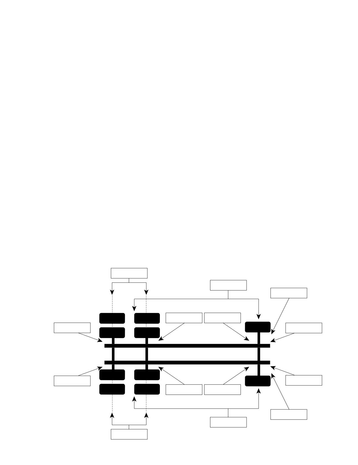
This will further relax the front suspension, giving you a
(bag) housing. Verify manufacturer’s recommendation for
correct toe reading. Once the steer tires are down, measure
vehicle type.
from side to side between the scribed lines, first rear,
3. Measure for tandem axle skew by measuring between the
then front, with a tapemeasure or a fine lined toe gauge
rimflanges. Kneel between the outside of the tires.Hook the
to determine relative toe. Do this with the paint cans on
metric tape measure at hub-height on one, and by using a
the ground, centered on the scribe line, and measure the
swinging arc on the other, determine the shortest distance
distance between the lines on the left and right tire at the
between them. Take a similar measurement on the other
paint can height. Subtract front from rear: positive result
side of the vehicle (tolerance is 1/8 inch or 3 mm between
indicates toe-in, negative is toe-out. At this paint can height:
axle ends).
total toe-in should be positive +1 mm so that the tires will
4. Measure for drive axle thrust by using the string from the
run in a straight line under a dynamic, loaded condition.
front drive axle to the steer position. Attach the string to the
Recommended toe setting is +1/16” (1.5 mm).
drive tire at hub-height, bring it across the rear sidewall,
6. If checking for camber, with wheels straight ahead, drop a
moveto the steering axle, bring the stringin toward the
plumbline off the front fender over the tire assembly center
front wheel until it touches the drive tire’s front sidewall,
and measure the distance, using millimeters, between the
and measure the distance between the string and disc face
string and rim flange at the top and bottom. Divide your
of the wheel (just below the dust cap). Repeat this method
difference by 10 to convert millimeters to degrees. Use the
ontheotherside.
paint can to extend out from the fender if necessary. Repeat
With all data recorded, review measurement of drive axle
the procedure on the other steer position. Consider any
offset. Any significant drive axle offset, if found (± 3/16” or
floor slope, mismatched inflation pressures, or mismatched
± 5 mm), must be factored into the readings of drive axle
tread depths.
thrust as determined above by adding or subtracting the
offset from the appropriate side(string to front wheel flange
Rear of Vehicle
measurement ± offset).
1. Measure for drive axle offset by measuring, at each drive
Drawapictureofthesteer and drive axle orientation
axle wheel position, from the inner wheel flange to the
using recorded axle skew measurements.
inside of the frame rail (tolerance: 3/16” or 5mm side to
Drive axle skew tolerance is based on wheel base:
side).
19/32” or 15 mm < 150 inch
2. Check ride height by measuring the distance from the
3/4” or 20 mm 150-200 inch
lower part of the frame rail to the bottom of the air spring
1” or 25 mm > 200 inch
ATTACC PLUS WORKSHEET
Front Tandem Axle Skew
String to Wheel
for Drive Axle Thrust
Spring to Flange
Drive Axle Offset
Steer Offset
Grease Zerk
Drive Axle Offset
to U-Bolt
Drive Axle Offset
Grease Zerk
to U-Bolt
Drive Axle Offset
Steer Offset
Spring to Flange
String to Wheel
for Drive Axle Thrust
Front Tandem Axle Skew
Section Ten: Appendix
167
CASING MANAGEMENT
TIRE MANAGEMENT
All of these changes lead to the casing arriving at the
retread stage with a higherlevel of fatigue. To utilize these
The goal of every truck operator is to achieve the
casings to their maximum, casing management should be
lowest possible operating cost, taking advantage of the
employedintheselection of the retread.
performance built into each high tech MICHELIN® radial
truck tire. Tire maintenance, proper inflation pressures,
repairs, vehicle alignment, and retreading, are all keys to
CASING MANAGEMENT IN THE PAST
help ensure maximized performance and extended casing
Highway fleets typically employ the casing management
life.
pattern below:
Position of
Over the past 10 years, a number of operational and
Tire First
Position of First
Subsequent
product changes have occurred that should be considered
Used On
Retread Use
Retread Use
when establishing tire use patterns. The single most
Steer
»
Drive or Trailer »
Drive or Trailer
important point of any program is “Know Your Customer.”
Drive
»
Drive
»
Drive or Trailer
Trailer
»
Trailer
»
Trailer
TIRE CHANGES
1. New Tires: Today’s wider treads and deeper tread
CASING FATIGUE
depths provide more original tread miles. The tire arrives
In termsof casing fatigue, the severity of useis as follows:
at the retreader withmore time in service,moremiles, and
• Drive Axle - most fatigue. New drive tires (lug type) often
exposure to road conditions.
canaccumulate twice asmanymiles (ormore) before
2. Retread Changes: Wider treads, new tread designs, and
retreading than new steer or trailer tires can. The same
new compounds have increased retread mileages.
is true for drive axle lug type retreads. The tires also run
hotter(deeper tread) and withmore torque.
VEHICLE CHANGES
• Steer Axle - moderate fatigue. Steer axle tires operate at
1. Longer Trailers: There has been a move from 40’ to 48’
higher average loads than drive or trailer tires (20 to 40%
and 53’ trailers as standards in the contract and private
higher). However, they wear out sooner than drive tires
carriage business.
and are moved to lighter axles in the retread stage.
2. Wider Trailers: Widths have increased from 96” to 102”.
• Trailer Axle - least fatigue. The trailer tire starts life with
The combination of longer and wider trailers increases the
a shallow (cooler) tread and is usually retreaded with a
frequency of the duals being curbed.
shallow retread. Annual miles are low. The trailer tire
3. Setback Front Axles: Moving the steer axle back
casing usually sees more curb abuse, neglect, and old age
increases stress on steer tires and load efficiency by allowing
problems.
better load distribution. The result is higher average axle
Thus, the practice of retreading new drive axle tires back to
loads.
the drive axle puts the most highly fatigued casing back onto
4. Electronic Engines: Better engine control and more
the most highly stressed wheel position.
efficient operation improve the ability of the vehicle to
maintain higher cruise speeds.*
CASING MANAGEMENT FOR THE FUTURE
The following guidelines are recommended in sorting
OPERATIONAL CHANGES
casings for their next tread life. Such a sorting would allow
1. Speed limit: The national limit has continually increased
the fleet and retreader to make better decisions regarding
the handling and utilization of casings recovered from 6x4,
in the past decade.*
2. GVW (Gross Vehicle Weight): With the Surface
4x2, and trailer applications. Casings that are judged to be
more “highly fatigued” should be retreaded in one of two
Transportation Assistance Act of 1983, the weight limits
ways:
went from 73,280 lbs. to 80,000 lbs. With setback axles, you
can realistically load to 80,000 lbs.
1. A low rolling resistance/low heat retread rubber in
3. Greater Vehicle Utilization: More loaded miles mean
rib and drive (consult your retread supplier).
productivity gains.
2. A shallow retread (no more than 15/32”).
These retreads will reduce the operating temperature in
the crown of the tire.
* Exceeding the legal speed limit is neither recommended nor endorsed.
Determining which tires are “highly fatigued” requires a
working knowledge of each fleet’s individual operation. The
following guidelines can be used:
1. Two or more repairs on the casing.
2. Heavy sidewall abrasion.
168 Section Ten: Appendix

TREAD SELECTION MATRIX
RETREAD RECOMMENDATIONS
Itwould seem best to adopt the casingmanagement
1. Follow the retread manufacturer’s recommendations.
pattern below for tires in highway service:
2. Use the preferred tread size.
Position of
3. Buff to the correct crown radius.
Tire First
Position of First
Subsequent
4. Use pilot skives to measure undertread; 2/32” to 3/32”
Used On
Retread Use
Retread Use
is all that should remain when buffing is complete.
Steer » Drive or Trailer
»
Trailer
Drive
» Drive or Trailer
» Trailer
PREVIOUS SERVICE LIFE
Trailer
» Drive or Trailer » Trailer
In light of all these conditions and recommendations,
the purchaser of casings for retreading should proceed
with caution. Use the tread selection matrix when
previous service life is unknown.
COLD CLIMATE PRESSURE CORRECTION DATA
Because the pressure inside a tire will decrease when
left column of the table to the right. Going across to the
the vehicle is taken from a warm environment to a cold
relevant outside ambient temperature you will find the
one, some adjustments may be necessary when adjusting
corrected inflation pressure to be used.
the tire pressures of a vehicle to be operated in very cold
For example:
temperatures.
• A log truck in Alaska has a front axle loaded weight
These adjustments are only necessary if the pressures
of 12,000 lbs.
are verified and adjusted inside a heated garage with an
• The truck is equipped with 11R24.5 MICHELIN®
air supply that is also at the higher room temperature. (No
XZY®3 tires.
adjustment necessary if done outside.)
• The recommended pressure for this fitment is 105.
In extreme cases, the following table should be used to
• The truck is parked overnight in a heated garage.
ensure that the operating pressure and deflection of tires
• The outside high forecasted for today is -20ºF.
are adequate at the outside ambient temperature.
• The tire pressures are checked and adjusted prior to
Using the load and pressure charts below, determine
leaving the heated garage.
the appropriate “Recommended Pressure” required for
According the chart below, the tires should be adjusted
the axle load. Then find the same pressure down the
to 128.
Adjusted Inflation Pressure (psi) when inflating indoors at 65°F [18°C]
Outside Ambient Temperature
Recommended
Pressure
F° 50°
40°
30°
20°
10°
0°
-10°
-20°
-30°
-40°
-50°
(psi)
C° 10°
4°
-1°
-7°
-12°
-18°
-23°
-29°
-34°
-40°
-46°
75
78
80
81
83
86
88
90
92
95
98
100
80
83
85
87
89
91
93
96
98
101
104
107
85
88
90
92
94
97
99
102
104
107
110
113
90
93
95
98
100
102
105
108
110
113
116
119
95
98
101
103
105
108
111
113
116
119
123
126
100
103
106
108
111
113
116
119
122
125
129
132
105
109
111
114
116
119
122
125
128
132
135
139
110
114
116
119
122
125
128
131
134
138
141
145
115
119
122
124
127
130
133
137
140
144
148
151
120
124
127
130
133
136
139
143
146
150
154
158
125
129
132
135
138
141
145
148
152
156
160
164
130
134
137
140
144
147
150
154
158
162
166
171
Do not drive on improperly inflated tires. Doing so may lead to excessive heat build up, tire
failure, injury or death.
Section Ten: Appendix
169
COST ANALYSIS
Each fleet operation is different, but there is one
Anestimate of the CPM obtained by different tires in
consistent goal and that is to achieve the best possible
different wheel positions is shown in the examples below.
operating cost. This section is designed to provide a guide
STEER AXLE
to determining a Cost Per Mile (CPM).
a. MICHELIN® X® LINE™ ENERGY Z
The simplest CPM is found by dividing the price of the
New Tire Price (estimated)
$616.00
tire and any retread by the totalmileage.While this is an
b. Residual Casing Value (estimated)
- $60.00
easy calculation, it is very misleading by ignoring many
c. Total Miles (estimated)
÷ 120,000.00
of the added benefits of the tire or the transfer of residual
d. CPM = per mile
$ 0.00463
casing value from one life to another.
DRIVE AXLE
Determining CPM by wheel position could provide
a. MICHELIN® X® LINE™ ENERGY D Energy
an important gauge for performance since each wheel
New Tire Price (estimated)
$670.00
position is a very special case with unique operating
b. Residual Casing Value (estimated)
- $60.00
requirements. Here are some of the key elements that
c. Total Miles (estimated)
÷ 250,000.00
need to be considered in any analysis:
d. CPM = per mile
$ 0.00508
1. Total mileage (considers new and retread mileage for
steer, drive, and trailer)
YOUR OPERATION
2. Residual casing values or casing resale value
a. New Tire Price
$
3. Requirements of the specific wheel position (steer,
b. Residual Casing Value
-
drive, and trailer)
c. Total Miles
÷
4. Repairability (dollars spent on additional mounts and
d. CPM = per mile
dismounts, repair time and labor)
5. Retreadability (additional casing purchases)
6. Fuel efficiency (see section below)
7. Total expected casing life
8. Labor (scheduled and unscheduled)
9. Road call (by shop personnel as well as Emergency
calls)
10. Disposal fees
11. Liability Insurance
170 Section Ten: Appendix
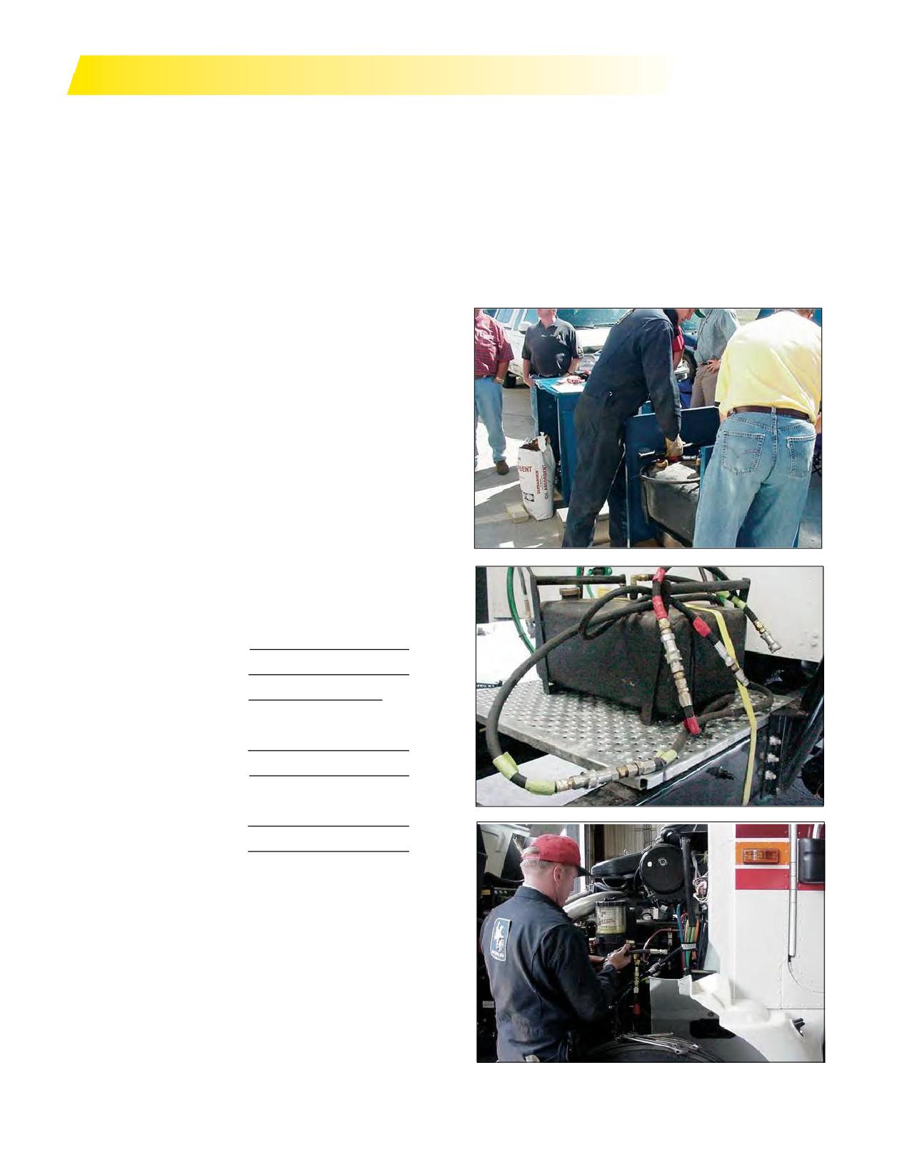
FUEL SAVINGS
Tires are a major component in the operating efficiency
on a circular route of 30miles, utilizing two vehicles of
of the vehicle as a result of their rolling resistance. Rolling
similar design and load with fuel supplied by portable
resistance is defined as how much effort it takes to roll
tanks. While using the same steer, drive, and trailer tires,
a tire with a given load and pressure. This tire rolling
a 2% ratio of both circuit time and of fuel weight
resistance is approximately 1/3 of the total vehicle
consumed must be established. All other variables will
resistance in 6x4 and 6x2 applications and as such, a
have been minimized by the constraints of the test
changeof3%inrolling resistance equals a 1% changein
procedures. Once the baseline has been established,
fuel consumption. Wind resistance and drive line friction
the test tires will be placed on the test vehicle, and the
account for the balance of the resistance.
difference in fuel consumption can be determined based
The MICHELIN® tires with Advanced Technology™
onthecompletionof 3-5 runsfalling within the 2% ratio.
compound are built to maximize energy conservation.
And the MICHELIN® X One® tire in drive and trailer
positions can even provide an increase over these
Advanced Technology tires.
Achange in rubber compound canprovide a large
reduction in rolling resistance, although it is unacceptable
to sacrifice durability and wet traction to achieve
this result. The Advanced Technology compound is
a sophisticated mix of tread design, complex rubber
chemistry, and advanced casing design all used while
maintaining mileage, wet traction, and durability.
As fuel costs continue to increase, fuel expenditures
become even more critical than tire expenditures. The ratio
of fuel to tire costs will range from 8:1 to 15:1 based on the
fl
operation in regional and long haul applications.
To calculate potential fuel savings:
A. Cost of Fuel/Gal.
$
B. Annual Miles
C. MPG of the Vehicle
MPG
D. Total Estimated Fuel
B ÷ C = gallon
E. % Fuel Savings
%
F. Estimated Fuel Savings
(E x D) = gallon
(F x A) = $
For a more in-depth calculation, consideration should
be given to looking at the rolling resistance factors for
the specific tires you are considering and ask for the
assistance of your Michelin Representative in determining
the savings. The next step would be to conduct an SAE
(Society of Automotive Engineers) Type J1376 Type II fuel
test and eliminate all the variables. Again, refer to your
Michelin Representative for assistance.
The SAE Type J1376 Fuel Test is a standard test
procedure for evaluating the relative fuel economy of
given vehicles. Test cycles are conducted over 2 to 3 days
Section Ten: Appendix
171
MOUNTING PROCEDURES FOR 16.00R20 AND 24R21
MOUNTING PROCEDURES FOR 16.00R20
O-RING SEAL
AND 24R21 MICHELIN® XL™ OR XZL™ TIRES
The most important part of tubeless mounting on
Correct procedure for mounting multi-piece wheels for
multi-piece wheels is the O-ring seal under the bead
tubeless truck tires includes proper mounting and correct
seat ring. It is imperative that the correct O-ring be used
pressure.
and properly installed. Check O-ring length and cross
Three-piece wheels consist of rim base, tapered bead
section diameter for correct fit. TheMICHELIN® O-ring
seat, and locking ring. Mounting tools include: large bore
seal reference number is 1506 for the 24R21, which is
valve, O-ring seal, brush or clean cloth with lubricant,
designated OR 6.8-21 for the 21-inch inside diameter.
small pallet of wooden blocks, inflation hose with a chuck
The16.00R20 usesO-ring referencenumber1681,
or large bore valve, and miscellaneous tools.
designated OR 6.6-20 for the 20-inch or the corner ring,
The first step inmounting is to properly position the
reference number 1443, designated A20-TYRAN. The
wheel base by placing the wheel on the small pallet or
corner ring has a slightly different mounting procedure
blocks to raise it off the floor, facilitating the lock ring
- see wheel manufacturer for proper procedures. Some
installation. Note that the wheel is placed on the support
commerciallyavailable O-rings are too long. If too long, it
with the fixed flange side down. Using the large bore
will push out of the groove breaking the seal and the tire
valve, lightly lubricate the rubber grommet on the valve
will loose tire pressure. Do not lubricate the O-ring prior
base; insert and secure with the hex nut of both sides.
to installation on the wheel. The lubricant tends to push
Always use a large bore valve and not a standard truck
the O-ring out of the groove breaking the seal.Make sure
valve since the larger diameter will permit better tire
both the O-ring and the groove are free of debris. Place
pressure flow and better bead seating.
the O-ring in the bottom groove; it should fit tightly but
not be excessively stretched.
WHEEL LUBRICATION
With a clean cloth or brush, lightly lubricate the rim
LUBRICATION OF THE O-RING
basecompletely except for the two upper grooves.
The outer surface of the O-ring should be lightly, but
Lubrication in these grooves can cause the O-ring to be
welllubricated to allow the tapered bead seat to slide
rolled out of the groove by the tapered bead seat when
easily over the seal during inflation. Remember an
inflating the assembly. It is important to use a heavy
incorrect O-ring or improper lubrication can force or
lubricant such as MICHELIN® Bib Grease or Murphy’s.
push the O-ring out of the slot upon inflation causing tire
Heavy lubricants do not dry as quickly, thus allowing
pressure loss. Snap the lock ring in the upper rim groove.
more time to seat the beads during inflation.
Check that the ring is fully seated in the groove.
LUBRICATION OF THE BEAD
INFLATION
Using a brush or clean cloth, lubricate the inside and
Place the assembly in the horizontal (preferred) or
outside of each tire bead area. This procedure plus the
vertical (if well lubricated) position for inflation in the
rimlubrication will allow the taperedbead seat ring to
restraining device and remove the valve core. This will
beinstalledmore easily and allow the tire beads to seat
allow the beads to slidemore easily into position. Inflate
properly during inflation.
to 80 psi for complete tire bead seating. Install the valve
core and then adjust pressure to that recommended for
TIRE PLACEMENT ON THE WHEEL
the load and condition.
Place the tire on the wheel base. This can be done
Remember the keys for good mounting are:
manually or by fork lift truck for easier handling. Exercise
1. Correct size, type, and compatibility of components
caution whensliding the forks below the sidewalls of
2. Proper lubrication and mounting procedures
the tires since an impact by the forks can damage the
3. 80 psi initial inflation pressure for bead seating,
casing cords. Lifting the tire by the beads can damage or
followed by adjustment to recommended pressure.
permanently distort the beads and should be avoided.
TAPERED BEAD SEAT RING
Adherence to these simple guidelines will ensure
The bead seat ring should be lubricated on both sides
maximized performance and minimized downtime due to
before placing it on the wheel base. This allows it to slide
tire mismount.
betweenthetire and wheelbasemoreeasilyandlater
Ifyou are having difficulty in mounting or cannot get
over the wheel base during inflation. Lubricating the bead
the assembly to inflate or hold tire pressure, an incorrect
seating surface facilitates concentric seating of the beads
component or incorrect inflation is probably the cause.
during inflation.
172 Section Ten: Appendix
TIRE REVOLUTIONS PER MILE CALCULATION
MEASURED TIRE REVOLUTIONS PER MILE
CALCULATED TIRE REVOLUTIONS
At Michelin, Tire Revolutions per Mile (tire RPM) are
PER MILE
determined using a method based on the SAE (Society of
Automotive Engineers) Recommended Practice J1025. The
Michelin Equation:
test tires are placed in a single fitment on the drive axle of
Tire RPM
=
20,168 / (O.D. - .8d)
the test vehicle, loaded to the maximum dual load rating
O.D.
= Overall Diameter
of the tire and set to the corresponding pressure. The
d
= Correction for deflection
vehicle is then driven on a test track at 45mph while the
revolutions are counted. Since speed minimally affects the
Deflection - e
= (O.D./2) - SLR
results for radial tires, other speeds are allowed. Four runs
SLR
= Static Loaded Radius
must be completed with results that are consistent within
(Ref. Michelin Truck Tire Data Book)
1%. The tire RPM specification is calculated as the average
(mean) of the four runs. The results are verified using
Example: 275/80R22.5 MICHELIN® X® MULTI DRIVE LRG
shorter distances that are more easily obtained. The test
tire is also compared to a known baseline tire on a road
New Tire
wheel. This latter method is very accurate and repeatable
O.D.
=
40.5
when using a similar baseline tire with a known tire RPM.
The SAE procedure recognizes that there will be some
SLR
=
19.0
variation within the test method. In fact, there are other
d
=
(40.5/2) - 19.0
factors that cause variation in tire RPM among similar
Deflection - e
=
1.25
tires. Please note that although similar tires may have
Tire RPM
=
20,168 / (40.5 - (.8 x 1.25))
the same overall diameter, it does not necessarily mean
=
20,168 / (40.5 - 1.0)
that they will have the same tire RPM. The SAE procedure
=
20,168 / 39.5
determines the tire RPM to within ± 1.5%.
Tire RPM
=
510.6 (Calculated) vs Data Book
(Measured) Tire Revs./Mile = 510
Some factors, which cause variation among tires, are:
• Load and Pressure - A difference in Load/Pressure
could alter the Tire Revs./Mile measurement by as
At 50% Worn
much as 1.5%. If pressure is constant, going from an
O.D.
=
39.7 (13/32nd used is approximately
empty vehicle to a fully loaded vehicle can change the
0.8 inch reduction in the O.D.)
Tire Revs./Mile by 1 to 1.5%.
SLR
=
18.6 (13/32nd used is approximately
• Treadwear - The Tire Revs./Mile varies from a new
a 0.4 inch reduction of SLR)
tire to a fully worn tire. This can affect Tire Revs./Mile
d
=
(39.7/2) - 18.6
by as much as 3% from the rated Tire Revs./Mile.
Deflection - e
=
1.25
• Tread Geometry - The height and stiffness of the
Tire RPM
=
20,168 / (37.9 - (.8 x 1.25))
blocks and the shape of the tread pattern can affect
=
20,168 / (37.9 - 1.0)
Tire Revs./Mile.
=
20,168 / 38.7
• Torque - The presence of driving and braking torque
Tire RPM
=
521 (Calculated)
can affect the Tire Revs./Mile.
• Type and Condition of Pavement - Asphalt vs.
concrete, wet vs. dry can create differencein Tire
Revs./Mile.
Section Ten: Appendix
173
OUT-OF-SERVICE CONDITIONS
DESCRIPTION
Code Key 21: New & Retread Tire Out-of-Service Conditions was developed for tire manufacturers as a means
of coding out-of-service conditions as determined by manufacturer/laboratory failure analysis. It is not meant to replace
related codes identified for use by technicians in Code Key 18: Technician Failure Code, or Code Key 82: Operator Vehicle/
Equipment Condition Report. Code Key 21 has two codes per condition, a two-character alpha code or an alternative four-
digit numeric code. Code Key 21 was introduced with the release of VMRS 2000™ Version 1.05.
NOTE: In release of VMRS that preceded VMRS 2000™, Code Key 21 was used redundantly to denote a vehicle group/
system. The information once contained in Code Key 21 was assigned to VMRS 2000™ Code Key 31 in 1997.
Code (Alpha)
Code (Numeric)
Description
Bead Area
FW
1101
Bead Damage from Rim Flange Wear
BO
1102
Bead Damage Due to Overload
TB
1103
Torn Beads
KB
1104
Kinked/Distorted Beads
BD
1105
Bead Deformation
BB
1106
Burned Beads
CD
1107
Bead Damage from Curbing
CS
1108
Reinforce/Chafer Separation
FC
1109
Lower Sidewall/Bead Area Flow Crack
Sidewall Area
SC
1201
Spread/Damaged Cord
SS
1202
Sidewall Separation
SI
1203
Sidewall Separation Damage Induced
ST
1204
Sidewall Separation Due to Tread Puncture
SO
1205
Sidewall Separation Due to Bead Damage
BM
1206
Branding Damage
CU
1207
Cuts and Snags
OD
1208
Damage from Object Lodged Between Duals
AB
1209
Sidewall Abrasion/Scuff Damage
WE
1210
Weathering/Ozone Cracking
RS
1211
Radial Split
SB
1212
Sidewall Bumps (Blisters)
DC
1213
Diagonal Cracking
HS
1214
Heavy Sidewall Splice
OZ
1215
Open Sidewall Splice
SP
1216
Sidewall Penetration
CW
1217
Crack at Edge of Retread Wing
CB
1218
Cracking Due to Excessive Sidewall Buff
ZP
1219
Circumferential Fatigue Rupture (Zipper)
Crown Area
BS
1301
Brake Skid Damage
WW
1302
Wild Wire
DL
1303
Delamination
LB
1304
Lug Base Cracking
CC
1305
Chipping/Flaking/Chunking Tread
DR
1306
Stone Drilling
RD
1307
Regrooving Damage
DD
1308
Dynamometer Type Damage
EX
1309
Excessive Wear
RT
1310
Rib Tearing
174 Section Ten: Appendix
Code (Alpha)
Code (Numeric)
Description
Crown Area (continues)
DG
1311
Defense Groove Tearing
GC
1312
Groove Cracking
SD
1313
Spin Damage
ED
1314
Electrical Discharge
PO
1315
Tread Surface Porosity
TN
1316
Tread Non-fill
BL
1317
Belt Lift/Separation
BE
1318
Belt Separation - Repair Related
TS
1319
Tread Lift/Separation
RE
1320
Retread Separation
TR
1321
Retread Separation - Repair Related
TE
1322
Retread Edge Lifting
BP
1323
Bond Line Porosity
MP
1324
Missed Puncture
SF
1325
Skive Failure
WL
1326
Wing Lift
MT
1327
Misaligned Tread
IT
1328
Improper Tread Width
TC
1329
Tread Chunking at Splice
OT
1330
Open Tread Splice
SH
1331
Short Tread Splice
BT
1332
Buckled Tread
Tire Interior
LP
1401
Inner Liner Split at Puncture
FO
1402
Foreign Object Inner Liner Damage
PS
1403
Pinch Shock
MD
1401
Tearing Mount/Demount Damage
OL
1405
Open Inner Liner Splice
LS
1406
Inner Liner Bubbles/Blisters/Separations
LC
1407
Inner Liner Cracking
PC
1408
Pulled/Loose Cords
TI
1409
Thin Inner Liner
PG
1410
Ply Gap
Improper/Failed Repairs
BA
1501
Improper Bead Repair
OW
1502
On-the-Wheel Repair
BZ
1503
Improper Spot Repair
RB
1504
Repair Related Bulge
WR
1505
Spot Repair Should Have Been a Section
IR
1506
Improper Nail Hole Repair
IA
1507
Improperly Aligned Repair
BR
1508
Bridged Repair
IS
1509
Improper Section Repair - Damage Not Removed
BI
1510
Bias Repair in Radial Tire
IP
1511
Improper Repair Unit Placement
UN
1512
Unfilled Nail Hole Repair
RC
1513
Repair Unit Cracking at Reinforcement
FL
1514
Failed Inner Liner Repair
RU
1515
Repair Failure from Underinflation
Section Ten: Appendix
175
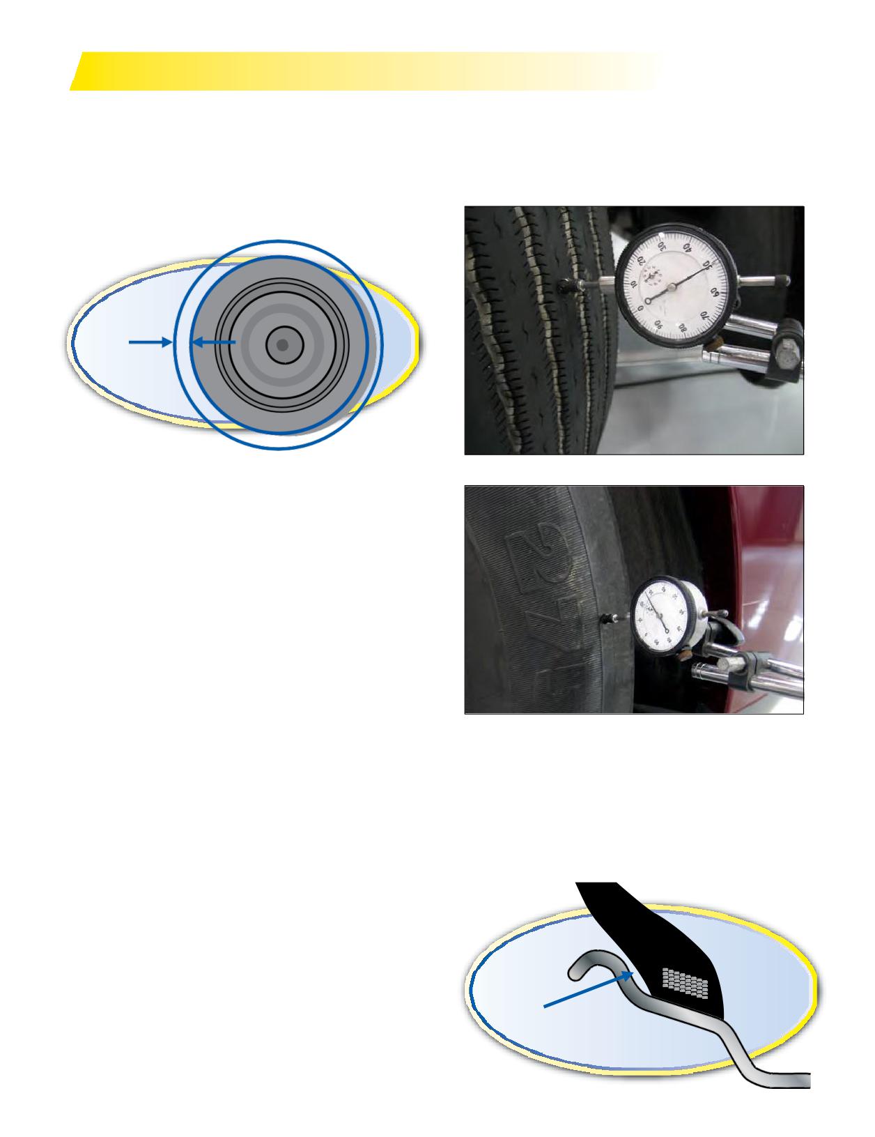
RUNOUT AND VIBRATION DIAGNOSIS
Rotating assembly runout can influence vehicle
If the value is between 0.001 inch and 0.060 inch,
vibration and contribute to irregular tire wear.
continue with procedures below. If the value is > 0.060
Following these procedures for verifying the
inch, remove and deflate the tire, break it loose from the
concentricity of the guide rib area as well as ensuring
wheel, lubricate, rotate the tire 180 degrees, reinflate, and
that both radial and lateral runout measurements are the
recheck runout.
lowest possible will aid in reducing any tire/wheel/hub
assembly contribution.
Radial Runout
Measuring Radial Runout on Center Rib
Tools needed:
• Tire runout gauge (or dial indicator)
• Pressure gauge
• Tread depth gauge
• Feeler gauge
• Six inch metal ruler
• Tire marking crayon
• Jack and jack stands
Thefirst stepis to eliminate possible sources of the
disturbance (operation conditions, alignment posture,
driveline component balance and angles, frame and
chassis concerns, fifth wheel placement, and possible
excessive stacked tolerances). Find out as much as you
can that may be related to the issue to aid in the initial
Measuring Lateral Runout on Outside Shoulder
diagnosis (maintenance file, test drive, driver interview).
Examine the assemblies for proper pressure, proper
Incorrect bead seating can occur on one or both bead
mounting, verify balance if balanced, inspect for tire and
seats. This usually results in a high radial and/or lateral
or wheel damage. Verify torque and proper component
reading. General cause is improper mounting procedures
assembly on tube-type or multi-piece assemblies. Proper
or wheelis at tolerancelimits. Itmay require taking 3
mounting procedure will reduce runout where it starts
radial readings to detect: outside shoulder, center rib, and
during the mounting process.
inside shoulder.
Jackup thefront endof the vehicle so axle is unloaded
and place jack stands for support. Inspect front end
components, including wheel bearing and kingpin play,
suspension and rear assemblies.
Use the tire runout gauge to check for both radial (top
photo) and lateral runout (bottom photo) for the rotating
assembly. Values over 0.060 inch will be a detectable
cause of vibration in steer assemblies and on recreational
Incorrect Bead Seating
vehicles. Current TMC (Technology & Maintenance
Council) assembly tolerances are 0.080 inches, radial and
lateral. See Page 58 for more information on Balance and
Runout.
176 Section Ten: Appendix
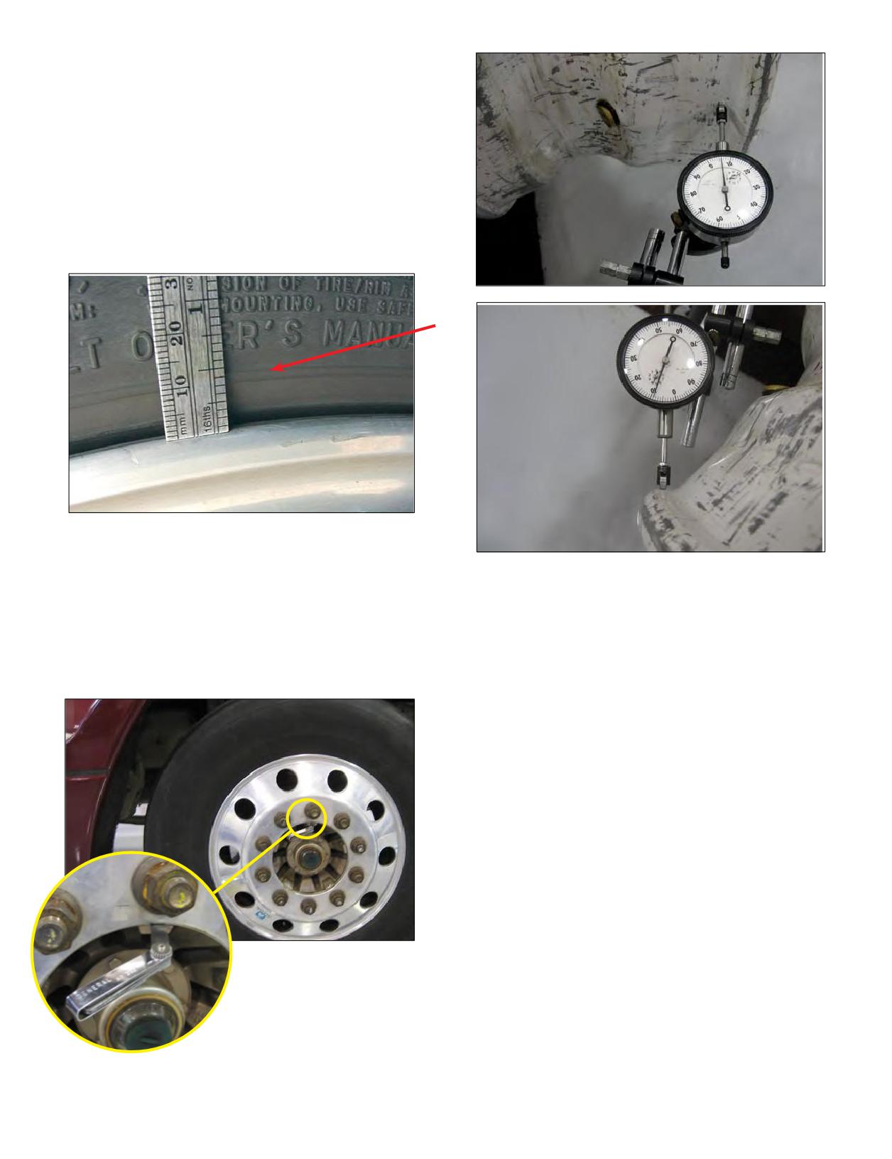
Note: The bead seating surface of the tire and wheel
do not match up as shown in previous illustration. This
incorrect seating is the result of mismount. The TMC
(Technology & Maintenance Council) specification
is 2/32nds (0.062 inch). If both wheel and tire are
lubricated and initial inflation is done with the tire flat,
then 1/32nd inch or less variance around the tire should
be obtainable.
Check for this mismount condition with the 6 inch
ruler, measuring in 4 locations around an unladen
assembly.
Check for hub to wheel clearance on hub piloted
assemblies with the feeler gauge. If the measured
Verification of radial (top photo) and lateral (bottom
highspot lines up with the feeler gauge gap, rotate
photo) wheel runoutis another step to be considered.
the assembly so the gap is at the top, loosen the lug
TMC tolerances are 0.070 inch on tubeless steel disc
nuts, and allow gravity to center the wheel on the hub.
wheels and 0.030 inch on tubeless aluminum disc wheels.
Hand tighten the top nut, tighten all nuts in the proper
sequence, recheck for runout, and retorque.
PROCEDURE TO CHECK THE WHEEL FOR
RADIAL AND LATERAL RUNOUT
• Mark two studs and the wheel with a crayon.
• Remove the tire and wheel assembly from the hub.
• Markthe tire and wheel at the valve stem.
• Dismount the tire from the wheel using proper
procedures.
• Clean the wheel flange area with a wire brush. Check
the wheel for any damage.
• Identify andmark the wheel toindicate where the
radial and lateral high and low spots were found on the
tire.
• Place the wheel back on themarked hubwith the
wheel matched to the marked studs. Use 3 lug nuts and
properly torque.
On cast spoke and
• Measure radial and lateral runout on the inside and
demountable rim assemblies,
outside flange.
loosen and properly retighten
• See if the readingsmatch up to the tire.
the rim clamp nuts to the
• Readings greater than 0.030 inch for aluminum wheels
proper torque. Recheck for
and 0.070 inch on steel wheels indicate high runout.
runout.
Section Ten: Appendix
177
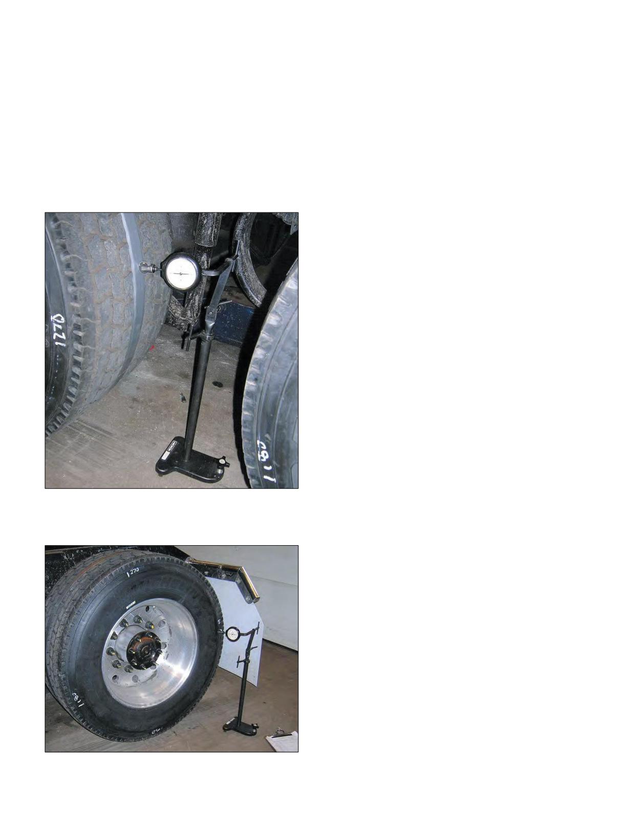
VIBRATION
Specifications for MICHELIN® X One® tires: See TMC RP
Tire-induced vibrations are generally the result
214D, Tire/Wheel End Balance and Runout for more details
of out-of-round assemblies. Common causes for out-
on radial and lateral runout readings.
of-round assemblies are components such as wheels,
Radial Runout < 0.125 inch
drums, and hubs and are corrected by changing the
Lateral Runout < 0.125 inch
individual component. The most common cause stems
from mismount or improper mounting procedures that
14” x 22.5 Aluminum Wheels < 0.030 inch
lead to the tire not seating concentrically with the wheel.
14” x 22.5 Steel Wheels < 0.070 inch
Whether it’s an individual component part or a mounting
issue, these problems can be identified easily by checking
Tools Required: Truck style runout gauge stand with dial
for radial and lateral runout.
indicator.
BALANCE
The Technology Maintenance Council (TMC) has
specifications for balancing.
Specifications for MICHELIN® X One® tires: See TMC RP
214D, Tire/Wheel End Balance and Runout, Appendix B
for more details on balance.
Steer:
24 oz
Drive:
28 oz
Trailer: 28 oz
Tools Required: A static or dynamic wheel balancer and
adapters to accommodate the larger MICHELIN® X One®
tire and wheel assembly.
When troubleshooting a ride disturbance, it is standard
practice to check the balance. Due to themajorimpact
runout has on balance, it is recommended that radial and
lateral runout are checked prior to attempting to balance
the assembly.
Radial Runout
NOTE: A piece of duct tape wrapped around the tread
will facilitate measuring radial runout on block style
drive tread designs.
Lateral Runout
178 Section Ten: Appendix
SERVICING MULTI-PIECE & SINGLE PIECE RIM/WHEELS
separation of a multi-piece rim/wheel, or during the
OSHA REGULATION:
sudden releaseof the contained air of a single piece rim/
SERVICING MULTI-PIECE AND
wheel.
SINGLE PIECE RIM/WHEELS
Rim manual means a publication containing
(a) Scope. (1) This section applies to the servicing of
instructions from the manufacturer or other qualified
multi-piece and single piece rim/wheels used on large
organization for correct mounting, demounting,
vehicles such as trucks, tractors, trailers, buses, and
maintenance, and safety precautions peculiar to the type
off-roadmachines. It does not apply to the servicing of
of wheel being serviced.
rim/wheels used on automobiles, or on pickup trucks and
Rim/wheel means an assemblage of tire, tube and liner
vans utilizing automobile tires or truck tires designated
(where appropriate), and wheel components.
‘‘LT.’’
Service or servicing means the mounting and
(2) This section does not apply to employers and places
demounting of rim/wheels and related activities such as
of employment regulated under the Construction Safety
inflating, deflating, installing, removing, and handling.
Standards, 29 CFR* part 1926; the Agriculture Standards,
Service area means that part of an employer’s premises
29 CFRpart 1928; the Shipyard Standards, 29 CFR part
used for the servicing of rim/wheels or any other place
1915;or the Longshoring Standards, 29 CFRpart 1918.
where an employee services rim/wheels.
(3) All provisions of this section apply to the servicing of
Single piece rim/wheel means the assemblage of single
both single piece rim/wheels and multi-piece rim/wheels
piece rim/wheel with the tire and other components.
unless designated otherwise.
Single piece wheel means a vehicle wheel consisting of
(b) Definitions. Barrier means a fence, wall, or other
one part, designed to hold the tire on the wheel when the
structure or object placed between a single piece rim/
tire is inflated.
wheelandanemployeeduringtireinflation, to contain
Trajectory means any potential path or route that a
the rim/wheel components in the event of the sudden
rim/wheel component may travel during an explosive
release of the contained air ofthe single piece rim/wheel.
separation, or the sudden release of the pressurized air,
Charts means the U.S. Department of Labor,
or anareaat whichan airblast from asingle piece rim/
Occupational Safety and Health Administration
wheel may be released. The trajectory may deviate from
publications entitled ‘‘Demounting and Mounting
paths which are perpendicular to the assembled position
Procedures for Truck/Bus Tires’’ and ‘‘Multipiece
of the rim/wheel at the time of separation or explosion.
Rim Matching Chart,’’ the National Highway Traffic
Wheel means that portion of a rim/wheel which provides
Safety Administration (NHTSA) publications entitled
the method of attachment of the assembly to the axle of a
‘‘Demounting and Mounting Procedures Truck/
vehicle and also provides themeans to contain the infl
Bus Tires’’ and ‘‘Multipiece Rim Matching Chart,’’
portion of the assembly (i.e., the tire and/or tube).
or any other poster which contains at least the same
(c) Employee training. (1) The employer shall provide
instructions, safety precautions, and other information
a program to train all employees who service rim/wheels
contained in the charts that is applicable to the types of
in the hazards involved in servicing those rim/wheels and
wheels being serviced.
the safety procedures to be followed.
Installing a rim/wheel means the transfer and
(i) The employer shall assure that no employee services
attachment of an assembled rim/wheel onto a vehicle
any rim/wheel unless the employee has been trained
axle hub. Removing means the opposite of installing.
and instructed in correct procedures of servicing the
Mounting a tire means the assembly or putting together
type of wheel being serviced, and in the safe operating
of the wheel and tire components to form a rim/wheel,
procedures described in paragraphs (f) and (g) of this
including inflation. Demounting means the opposite of
section.
mounting.
(ii) Information to be used in the training program shall
Multi-piece rim/wheel means the assemblage of a multi-
include, at a minimum, the applicable data contained
piece wheel with the tire tube and other components.
in the charts (rim manuals), and the contents of this
Multi-piece wheel means a vehicle wheel consisting of
standard.
two or more parts, one of which is a side or locking ring
(iii) Where an employerknows or has reason to
designed to hold the tire on the wheel by interlocking
believe that any of his employees is unable to read and
components when the tire is inflated.
understand the charts or rim manual, the employer shall
Restraining device means an apparatus such as a cage,
assure that the employee is instructed concerning the
rack, assemblage of bars and other components that will
contents of the charts and rim manual in a manner which
constrain all rim/wheel components during an explosive
*29 CFR - Title 29, Labor; Code of Federal Regulations
Section Ten: Appendix
179
the employee is able to understand.
(E) Other structural damage which would decrease its
(2) The employer shall assure that each employee
effectiveness.
demonstrates and maintains the ability to service rim/
(iv) Restraining devices or barriers removed from
wheels safely, including performance of the following
service shall not be returned to service until they
tasks:
are repaired and reinspected. Restraining devices or
(i) Demounting of tires (including deflation);
barriers requiring structural repair such as component
(ii) Inspection and identification of the rim/wheel
replacement or rewelding shall not be returned to service
components;
until they are certified by either the manufacturer or a
(iii) Mounting of tires (including inflation with a
Registered Professional Engineer as meeting the strength
restraining device or other safeguard required by this
requirements of paragraph (d)(3)(i) of this section.
section);
(4) The employer shall furnish and assure that an air
(iv) Use of the restraining device or barrier and other
line assembly consisting of the following components be
equipment required by this section;
used for inflating tires:
(v) Handling of rim/wheels;
(i) A clip-on chuck;
(vi) Inflation of the tire when a single piece rim/wheel is
(ii) Anin-line valve with a pressure gauge or a
mounted on a vehicle;
presettable regulator; and
(vii) An understanding of the necessity of standing
(iii) Asufficient length of hose between the clip-on
outside the trajectory both during inflation of the tire and
chuck and the in-line valve (if one is used) to allow the
during inspection of the rim/wheel following inflation;
employee to stand outside the trajectory.
and
(5) Current charts or rim manuals containing
(viii) Installation and removal of rim/wheels.
instructions for the type of wheels being serviced shall be
(3) The employer shall evaluate each employee’s
available in the service area.
ability to perform these tasks and to service rim/wheels
(6) The employer shall furnish and assure that only
safely, and shall provide additional training as necessary
tools recommended in the rim manual for the type of
to assure that each employee maintains his or her
wheel being serviced are used to service rim/wheels.
proficiency.
(e) Wheel component acceptability. (1) Multi-piece
(d) Tire servicing equipment. (1) The employer shall
wheel components shall not be interchanged except as
furnish a restraining device for inflating tires on multi-
provided in the charts or in the applicable rim manual.
piece wheels.
(2) Multi-piece wheel components and single piece
(2) The employer shall provide a restraining device or
wheels shall be inspected prior to assembly. Any wheel or
barrier for inflating tires on single piece wheels unless the
wheel component which is bent out of shape, pitted from
rim/wheel will be bolted onto a vehicle during inflation.
corrosion, broken, or cracked shall not be used and shall
(3) Restraining devices and barriers shall comply with
be marked or tagged unserviceable and removed from the
the following requirements:
service area. Damaged or leaky valves shall be replaced.
(i) Each restraining device or barrier shall have the
(3) Rim flanges, rim gutters, rings, bead seating
capacity to withstand the maximum force that would be
surfaces, and the bead areasof tires shall be free of any
transferred to it during a rim/wheel separation occurring
dirt, surface rust, scale or loose or flaked rubber build-up
at 150 percent of the maximum tire specification pressure
prior to mounting and inflation.
for the type of rim/wheel being serviced.
(4) The size (bead diameter and tire/wheel widths) and
(ii) Restraining devices and barriers shall be capable of
type of both the tire and the wheel shall be checked for
preventing the rim/wheel components from being thrown
compatibility prior to assembly of the rim/wheel.
outside or beyondthedevice or barrier for any rim/wheel
(f) Safe operating procedure-multi-piece rim/wheels.
positioned within or behind the device;
The employer shall establish a safe operating procedure
(iii) Restraining devices and barriers shall be visually
for servicing multi-piece rim/wheels and shall assure that
inspected prior to each day’s use and after any separation
employees are instructed in and follow that procedure.
of the rim/wheel components or sudden release of
The procedure shall include at least the following
contained air. Any restraining device or barrier exhibiting
elements:
damage such as the following defects shall be immediately
(1) Tires shall be completely deflated before
removed from service:
demounting by removal of the valve core.
(A) Cracks at welds;
(2) Tires shall be completely deflated by removing the
(B) Cracked or broken components;
valve core before a rim/wheel is removed from the axle in
(C) Bent or sprung components caused by mishandling,
either of the following situations:
abuse, tire explosion or rim/wheel separation;
(i) When the tire has been driven underinflated at 80%
(D) Pitting of components due to corrosion; or
or less of its recommended pressure, or
180 Section Ten: Appendix
(ii) When there is obvious or suspected damage to the
(2) Mounting anddemountingofthetire shall be
tire or wheel components.
done only from the narrow ledge side of the wheel. Care
(3) Rubber lubricant shall be applied to bead and
shall be taken to avoid damaging the tire beads while
rim mating surfaces during assembly of the wheel and
mounting tires on wheels. Tires shall be mounted only on
inflation of the tire, unless the tire or wheel manufacturer
compatible wheels of matching bead diameter and width.
recommends against it.
(3) Nonflammable rubber lubricant shall be applied
(4) If a tire on a vehicle is underinflated but has more
to bead and wheel mating surfaces before assembly of
than 80% of the recommended pressure, the tire may be
the rim/wheel, unless the tire or wheel manufacturer
inflated while the rim/wheel is on the vehicle, provided
recommends against the use of any rubber lubricant.
remotecontrol inflation equipmentis used andno
(4) Ifa tire changingmachine is used, the tire shall be
employees remain in the trajectory during inflation.
inflated only to the minimum pressure necessary to force
(5) Tires shall be inflated outside a restraining device
the tire bead onto the rim ledge while on the tire changing
only to a pressure sufficient to force the tire bead onto
machine.
the rim ledge and create anairtight seal with the tire and
(5) If a bead expander is used, it shall be removed
bead.
before the valve core is installed and as soon as the rim/
(6) Whenever a rim/wheel is in a restraining device the
wheel becomes airtight (the tire bead slips onto the bead
employee shall not rest or lean any part of his body or
seat).
equipment on or against the restraining device.
(6) Tires may be inflated only when contained within a
(7) After tire inflation, the tire and wheel components
restraining device, positioned behind a barrier, or bolted
shall be inspected while still within the restraining device
on the vehicle with the lug nuts fully tightened.
to make sure that they are properly seated and locked.
(7) Tires shall not beinflated when any flat, solid
If further adjustment to the tire or wheel components
surface is in the trajectory and within one foot of the
is necessary, the tire shall be deflated by removal of the
sidewall.
valve core before the adjustment is made.
(8) Employees shall stay out of the trajectory when
(8) No attempt shall be made to correct the seating of
inflating a tire.
side and lock rings by hammering, striking, or forcing the
(9) Tires shall not be inflated to more than the inflation
components while the tire is pressurized.
pressure stamped in the sidewall unless a higher pressure
(9) Cracked, broken, bent, or otherwise damaged rim
is recommended by the manufacturer.
components shall not be reworked, welded, brazed, or
(10) Tires shall not be inflated above the maximum
otherwise heated.
pressure recommended by the manufacturer to seat the
(10) Whenever multi-piece rim/wheels are being
tire bead firmly against the rim flange.
handled, employees shall stay out of the trajectory unless
(11) No heat shall be applied to a single piece wheel.
the employer can demonstrate that performance of the
(12) Cracked, broken, bent, or otherwise damaged
servicing makes the employee’s presence in the trajectory
wheels shall not be reworked, welded, brazed, or
necessary.
otherwise heated.
(11) No heat shall be applied to a multi-piece wheel or
Reprints of the charts are available through the Occupational Safety and
wheel component.
Health Administration (OSHA) Area and Regional Offices. The address and
(g) Safe operating procedure-single piece rim/wheels.
telephone number of the nearest OSHA office can be obtained by looking
in the local telephone directory under U.S. Government, U.S. Department of
The employer shall establish a safe operating procedure
Labor, Occupational Safety and Health Administration.
for servicing single piece rim/wheels and shall assure that
Single copies are available without charge. Individuals, establishments and
employees are instructed in and follow that procedure.
other organizations desiring single or multiple copies of these charts may
order them from the OSHA Publications Office, U.S. Department of Labor,
The procedure shall include at least the following
Room N-3101, Washington, DC 20210, Telephone (202) 219-4667.
[49 FR 4350, Feb. 3, 1984, as amended at 52 FR 36026, Sept. 25, 1987; 53 FR
elements:
34737, Sept. 8, 1988; 61 FR 9239, Mar. 7, 1996].
(1) Tires shall be completely deflated by removal of the
valve core before demounting.
Section Ten: Appendix
181
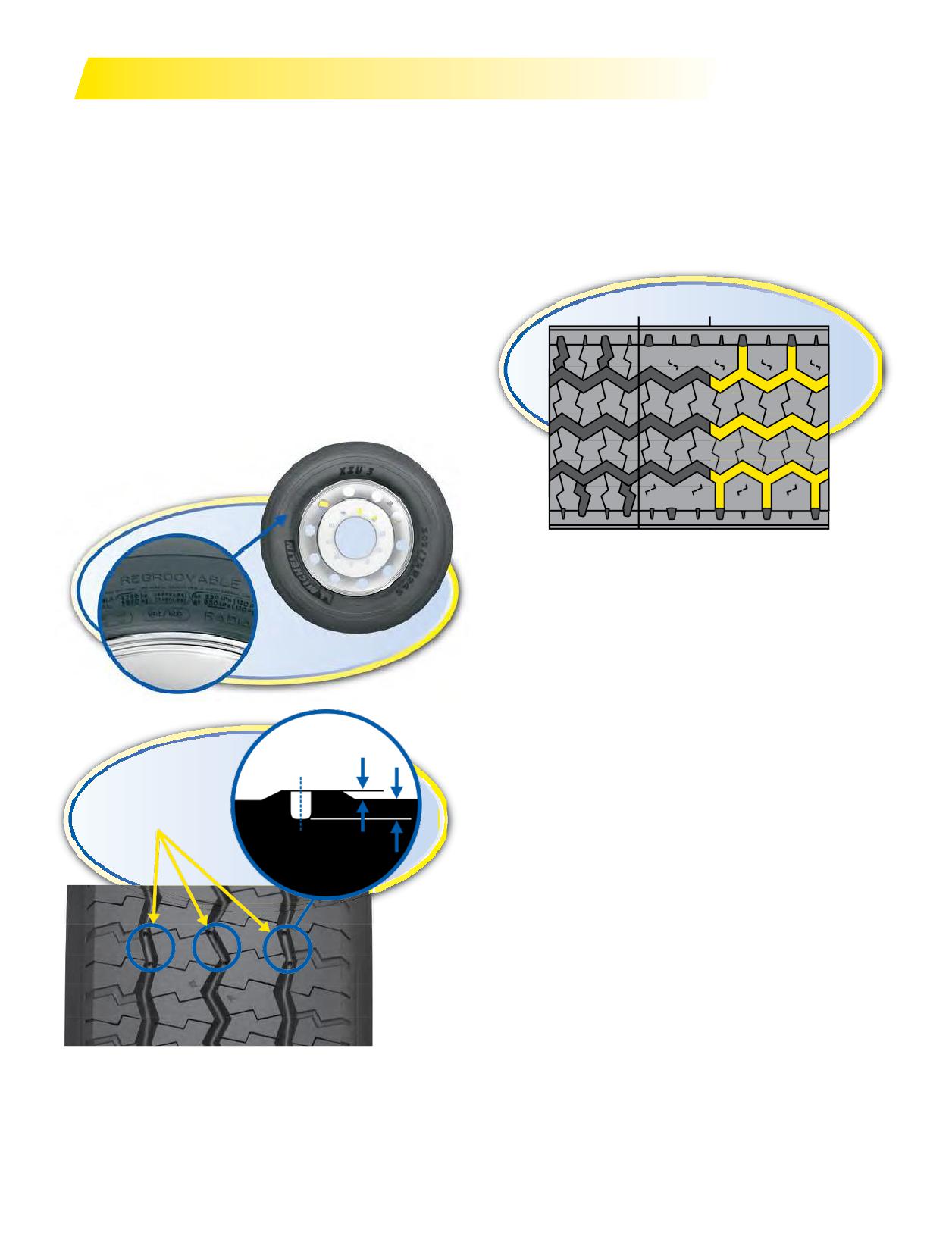
REGROOVING
Only MICHELIN® truck tires that are marked
One of the regulations governing regrooving tires
“REGROOVABLE” on the sidewall may be regrooved. After
requires that a regrooved tire must have a minimum
regrooving, you must have at least 3/32” of under tread
of 90 linear inches of tread edge per linear foot of the
covering the top ply. If steel is exposed, the tire must be
circumference.
scrapped or retreaded. In addition, some tread designs
The MICHELIN® XZU®2 tire has only 3 circumferential
will have a regrooving depth indicator as shown below.
tread grooves. To meet the 569.7 (iii) requirement,
Do not regroove below the depth of the indicator.
additional lateral grooves must be added as shown below.
Regrooving depth indicators are holes (of 4mm depth)
situated on the treadwear indicator to indicate the
recommended regrooving depth for these tires.
New
Used
Regrooved
It is the responsibility of the regroover to assure that
all Federal Regulations are met. See US Code of Federal
Regulations: Title 49, Transportation; Parts 569 and
393.75.
1.6 mm
4.0 mm
Depth Indicators
1.6 mm = 2/32nds
4.0 mm = 5/32nds
182 Section Ten: Appendix
(vii) If the tire issiped by cutting the tread surface
REGROOVING CODE
U. S. CODE OF FEDERAL REGULATIONS:
without removing rubber, the tire cord material shall not
TITLE 49, TRANSPORTATION; PARTS 569.7 AND 393.75
be damaged as a result of the siping process, and no sipe
(EXTRACTS)
shall be deeper than the original or retread groove depth.
For complete regulations, go to: ecfr.gpoaccess.gov
(b) Siped regroovable tires. No person shall sell, offer
for sale, or introduce for sale or deliver forintroduction
569.7 REQUIREMENTS.
into interstate commerce a regroovable tire that has
(a) Regrooved tires. (1) Except as permitted by
been siped by cutting the tread surface without removing
paragraph (a)(2) of this section, no person shall sell,
rubber if the tire cordmaterial is damaged as a result of
offer for sale, or introduce or deliver for introduction
the siping process, or if the tire is siped deeper than the
into interstate commerce regrooved tires produced by
original or retread groove depth.
removing rubber from the surface of a worn tire tread to
generate a new tread pattern. Any person who regrooves
393.75 TIRES.
tires and leases them to owners or operators ofmotor
(a) No motor vehicle shall be operated on any tire that -
vehicles and any person who regrooves his own tires
(1) Has body ply orbeltmaterial exposed through the
for use on motor vehicles is considered to be a person
tread or sidewall,
delivering for introduction into interstate commerce
(2) Has any tread or sidewall separation,
within the meaning of this part.
(3) Is flat or has an audible leak, or
(2) A regrooved tire may be sold, offered for sale, or
(4) Has a cut to the extent that the ply or belt material is
introduced for sale or delivered for introduction into
exposed.
interstate commerce only if it conforms to each of the
(b) Any tire on the front wheels of a bus, truck, or truck
following requirements:
tractor shall have a tread groove pattern depth of at least
(i) The tire being regrooved shall be a regroovable tire;
4⁄32 of an inch when measured at any point on a major
(ii) After regrooving, cord material below the grooves
tread groove. The measurements shall not be made where
shall have a protective covering of tread material at least
tie bars, humps, or fillets are located.
3 ⁄ 32-inch thick;
(c) Except as provided in paragraph (b) of this section,
(iii) After regrooving, the new grooves generated into
tires shall have a tread groove pattern depth of atleast
the tread material and any residual original molded tread
2⁄32 of an inch when measured in a major tread groove.
groove which is at or below the new regrooved depth shall
The measurement shall not be made where tie bars,
have aminimum of 90 linear inches of tread edges per
humps or fillets are located.
linear foot of the circumference;
(d) No bus shall be operated with regrooved, recapped
(iv) After regrooving, the new groove width generated
or retreaded tires on the front wheels.
into the tread material shall be a minimum of 3/16-inch
(e)Aregrooved tire with aload-carrying capacity equal
and a maximum of 5⁄16-inch;
to or greater than 2,232 kg (4,920 pounds) shall not be
(v) After regrooving, all new grooves cutinto the tread
used on the front wheels of any truck or truck tractor.
shall provide unobstructed fluid escape passages; and
(vi) After regrooving, the tire shall not contain any of the
following defects, as determined by a visual examination
of the tire eithermounted on the rim, or dismounted,
whichever is applicable:
(A) Cracking which extends to the fabric,
(B) Groove cracks or wear extending to the fabric, or
(C) Evidence of ply, tread, or sidewall separation;
Section Ten: Appendix
183
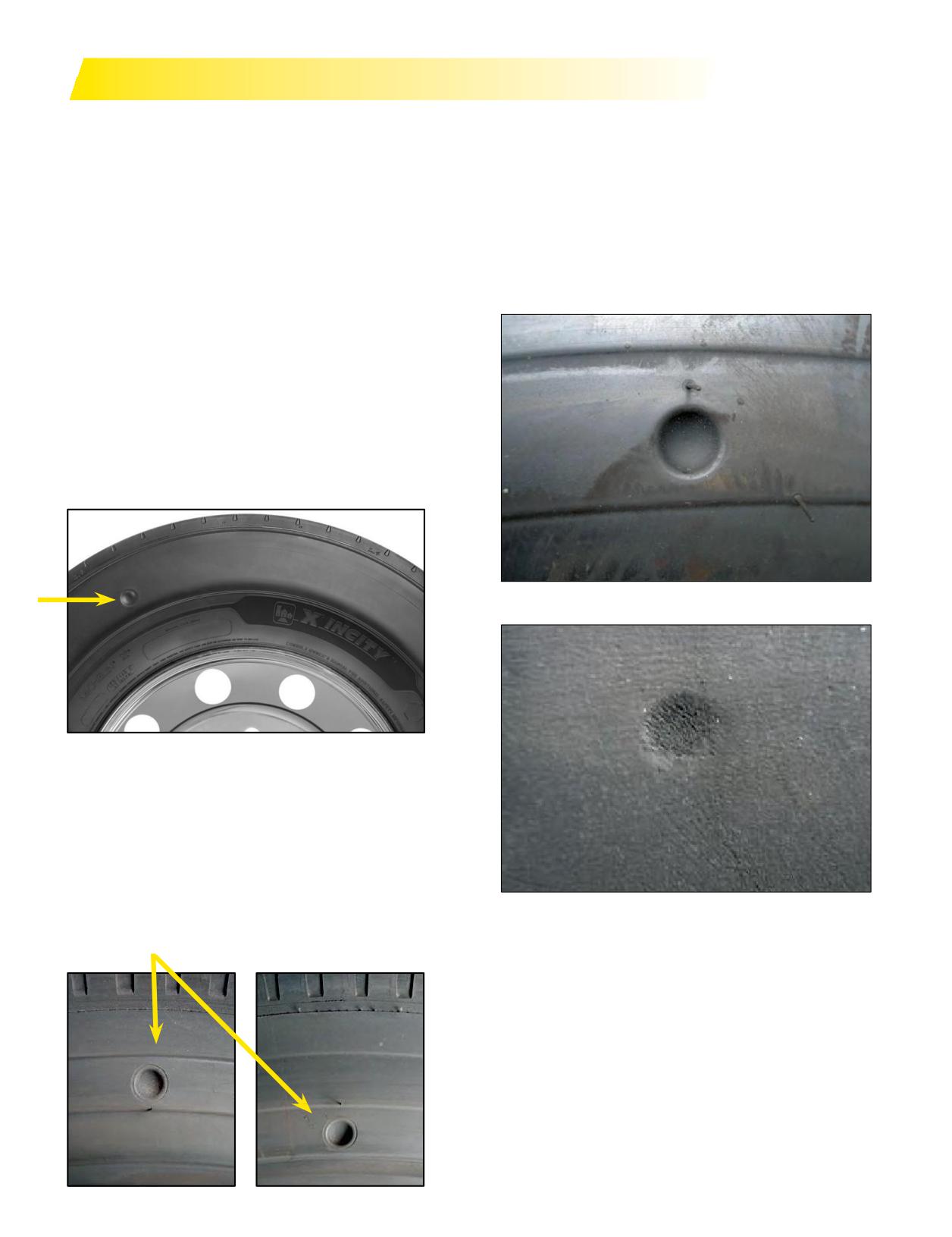
TRANSIT APPLICATIONS IN URBAN CONDITIONS
Transit applications in Urban conditions may
If no sidewall depth indicator is available and the
experience sidewall abrasion damage from rubbing the
product you are using it is not maximized for urban use
tire’s sidewall along a curb. This damage is primarily
the tire should accept some lighter levels of tire curbing.
found on the right side of the vehicle on the front and rear
Whenthesidewall writing and beautyrings areworn offit
positions. MICHELIN® X® INCITY™ Z and XZU®3 transit
is time to rotate sidewalls.
tires are designed to operatein these conditions and offer
Prior to rotating the tire sidewall, the sidewall should
additional sidewall protection in these situations. The
be examined tomake sure there are no cords exposed or
Urban tires also have a molded sidewall depth indicator
cuts deeper than 3 mm. If these conditions exist, the tire
to assist in knowing how deep the tire can wear before
should be removed and scrapped.
rotating away from that scrub position.
NOTE: Not all tire sidewall depth indicators are located
along the same plane in the sidewall.
MICHELIN® X® INCITY™ Z TIRE
The MICHELIN® X® INCITY™ Z tire has sidewall
depth indicators at 4 identical locations. Therefore, if
very little or no sidewall depth indicator is visible on
the MICHELIN® X® INCITY™ Z tire it is time to rotate
sidewalls.
New Sidewall Depth Indicators
MICHELIN® XZU®3 TIRE
The MICHELIN® XZU®3 tire has the depth indicators
in opposite placement at 2 different heights. There are 4
sidewall depth indicators located at 2 different positions
on each sidewall with a depth of 6 mm. The indicators
are diametrically opposite each other on the same side.
When two of the depth indicators wear down to the point
that they disappear the tire needs to be rotated with that
Worn Sidewall Depth Indicators
sidewall away from the curb.
184 Section Ten: Appendix
“THE CRITICAL 6”
FACTORS THAT COST FLEETS MONEY
Goal: Install suitable valve caps on all wheel positions.
Consider the use of inflate-thru valve caps for easier
Overall Goal: Maintain all tires at the fleet target
pressure maintenance.
inflation pressure based on the manufacturers’
Effect: The number one cause of tire pressure loss can
application data book for the particular axle load. When
be attributed to missing valve caps. Operating without
monitoring inflation pressure well maintained fleets deep
valve caps can result in under inflation and the conditions
the tires within 5 psi of this setting, and notmore than 5
mentioned above in 1 and 2.
psi different than the dual tire next to it in operation.
4. Dual Mismatch Inflation Pressure
1. Low Inflation Pressure
Dual mismatched pressures can cause a permanent
Under-inflation is the biggest issue in the industry.
irregular wear pattern to develop and within a few weeks
It is the number one cause of premature tire removal.
canpotentially be a cause of early tire removal. Dual
With the advancement in today’s radial casing, it is
mismatched pressure will also affect the matched tire,
virtually impossible to determine if a tire is properly
causing accelerated tread wear and casing fatigue.
inflated without using a pressure gauge. Periodically
Goal: Maintain all tires at the fleet target inflation
calibrate the gauges using a master gauge. Over time,
pressure based on the manufacturers’ application data
usage conditions can cause a pressure gauge to loose
book for the particular axle load. Well maintained fleets
accuracy beyond the 2 psi manufactures tolerance range.
keep the tires within 5 psi of this setting when monitoring
The time and effort required to verify gauges and to check
inflation pressure.
tire pressure is time well spent.
Effect: This irregular wear can result in early removal or
Goal: Maintain all tires at the fleet target inflation
require tire rotation to minimize the effect.
pressure based on the manufacturers’ application data
book for the particular axle load.
5. Dual Mismatch Height
Effect: An inflation pressure mismatch of greater than
Dual mismatch tread depths (tire height differences)
five psi will result in the two tires of a dual assembly
will cause irregular wear. Additionally, the larger tire (the
being significantly different in circumference resulting
one with the greatest tread depth) will become over-
in irregular wear and can alsolead to eventual tireloss
fatigued due to bearing more weight, this accelerates
duetoprematurecasingfatigue. A difference of five psi
premature casing failure.
between steer tires will cause the vehicle to pull to the
Goal: Match tires in dual assembly with equal tread
side with the lower pressure. Additionally, under inflation
depths. Well maintained fleets use +/- 4/32" of tread
results in internal tire heat build up and potentially
depth as maximum allowable difference in overall height
premature tire failure.
between the duals.
Effect: Dual mismatch tread depths can cause a
2. High Inflation Pressure
permanent irregular wear pattern in a few weeks resulting
Over inflated tires increase the likelihood of crown cuts,
in early removal or alost casing.
impact breaks, punctures, and shock damage resulting
fromthedecreaseof sidewall flexing and anincreasein
6. Irregular Wear
firmness of the tread surface.
Proper inflation pressure, correct toe settings and
Goal: Maintain all tires at the fleet target inflation
proper alignment can prevent most irregular wear.
pressure based on the manufacturers’ application data
Steer, drive, and trailer axle alignment verification and/
book for the particular axle load.
or correction can be performed with a minimal cost or
Effect: Increases the probability of potential casing
investment in equipment.
damage. This change in contact patch footprint could
Goal: Reduce irregular wear by proactive tire and
result in a reduction of traction and tread life.
vehicle maintenance programs.
Effect: Once a wear pattern develops, it will continue
3. Missing Valve Caps
until the tire is rotated or removed to be retreaded or
Missingvalve caps are a primary source oflow inflation
scrapped. Diagnosis and correction of the cause is part
pressure. Valve caps are used to keep debris out of the
of the solution in preventing future conditions. Average
core and act as a secondary air seal if the valve core
occurrence of irregular wear typically results in a loss
happensto leak.Verify thereis a good tight seal by use
of tread life resulting in a much higher total cost of
of a spray type leak detector. A good “metal” cap with a
ownership.
rubber seal will hold tire pressure without a valve core.
Section Ten: Appendix
185
PUBLICATIONS, VIDEOS, AND WEBSITES
Publications - Data Books:
BFGoodrich® Commercial Truck Tires Data Book
BWL42029
MICHELIN® Agricultural Tire Data Book
MUT41305
MICHELIN® Data Book (Passenger Tire and Light Truck Tire)
MDL41780
MICHELIN® Earthmover and Industrial Data Book
MEL40017
MICHELIN® Truck Tire Data Book: RV Tires, Commercial Light Truck Tires, Truck Tires and Retreads
MWL40731
Uniroyal Truck Tire Data Book
UWL10000
Publications - References:
Cage It Poster 24”x36”
MWT43142
Crown/Sidewall Repair Template
MWT40192
MICHELIN® Earthmover and Industrial Tire Reference Brochure
MEL41736
MICHELIN® RV Tires
MWL43146
MICHELIN® TruckTire Nail Hole Repair Procedures
MWT40163
Nail Hole Repair Poster 24”x36”
MWT43210
The Usual Suspects Drive, Flyer
MWT43661
The Usual Suspects Drive, Poster 24”x36”
MWT43962
The Usual Suspects Steer, Flyer
MWT43963
The Usual Suspects Steer, Poster 24”x36”
MWT43964
The Usual Suspects Trailer, Flyer
MWT43965
The Usual Suspects Trailer, Poster 24”x36”
MWT43966
Publications - Warranties:
Agricultural Tires Limited Manufacturer’s Warranty (MICHELIN®/KLÉBER®)
XUM41727
BFGoodrich® Truck Tire Operator’s Manual and Limited Warranty
BMW40844
Earthmover Limited Tire Warranty
MEE40022
Michelin Retread Technologies, Inc. National Limited Warranty
MWW41268
MICHELIN® Truck Tire Operator’s Manual and Limited Warranty
MWE40021
Passenger and Light Truck - MICHELIN® Complete Warranty
MDW41156
Uniroyal Truck Tire Operator’s Manual and Limited Warranty
UWW10000
Technical Bulletins: www.michelintruck.com
Videos:
Websites:
186 Section Ten: Appendix
Industry Contacts And Publications:
OSHA (Occupational Safety and Health Administration)
- Safety StandardNo. 29Cfr, Part1910.177
USTMA (U.S. Tire Manufacturers Association) - Formally RMA
- Care And Service of Truck and Light Truck Tires
- Inspection Procedures to Identify Potential Sidewall “Zipper Ruptures” in Steel Cord Radial Truck,
Bus and Light Truck Tires (TISB 33, Number 6)
SAE (Society of Automotive Engineers)
TIA (Tire Industry Association)
- Commercial Tire Service Manual
TMC (Technology & Maintenance Council)
- TMC RP 201D, Tire Flap and Rim Dimensions
- TMC RP 203D, Truck Tire Regrooving
- TMC RP 205B, Use of Tire Bead Lubricants
- TMC RP 206B, Tire Repair Procedures
- TMC RP 208E, Tire Cost Determination
- TMC RP 209E, Tire and Rim Safety Procedures
- TMC RP 210D, Radial Tire Construction Terminology
- TMC RP 211B, Rim and Wheel Selection and Maintenance
- TMC RP 212D, Industry Advisory for Retreading Truck and Bus Tires
- TMC RP 213E, RMA Truck Tire and Wheel-Related Publications
- TMC RP 214D, Tire/Wheel End Balance and Runout
- TMC RP 215D, Sources of Tire and Wheel Information
- TMC RP 216C, Radial Tire Conditions Analysis Guide
- TMC RP 217D, Attaching Hardware for Disc Wheels
- TMC RP 218E, DOT Tire Identification Codes
- TMC RP 219C, Radial Tire Wear Conditions and Causes (A Guide to Wear Pattern Analysis)
- TMC RP 220D, Tire Tread Design Selection
- TMC RP 221D, Retread Plant Inspection Guidelines
- TMC RP 222C, User’s Guide to Wheels and Rims
- TMC RP 223D, Tire Selection Process
- TMC RP 224D, Tire Retread Process
- TMC RP 226C, Radial Tire Repair Identifier (Blue Triangle)
- TMC RP 228B, Guidelines for Tire Radio Frequency Tags and Readers
- TMC RP 229B, Computerized Tire Recordkeeping
- TMC RP 230B, Tire Test Procedures for Treadwear, Serviceability and Fuel Economy
- TMC RP 231, Wheel System Maintenance Labeling Guidelines
- TMC RP 232A, Zipper Rupture Inspection Procedures for Light- and Medium-Duty Truck Tires
- TMC RP 233B, Radial Tire Nail Hole Repair Training Guidelines
- TMC RP 234A, Proper Valve Hardware Selection Guidelines
- TMC RP 235, Guidelines for Tire Inflation Pressure Maintenance
- TMC RP 236A, Outsourcing Guidelines for Tire and Wheel Maintenance
- TMC RP 237A, Retorquing Guidelines for Disc Wheel
- TMC RP 238A, Troubleshooting Disc Wheel Looseness
- TMC RP 239A, Commercial Vehicle Tire Inflation and/or Monitoring Systems Guidelines
- TMC RP 240A, Steel Wheel and Rim Refinishing Guidelines
- TMC RP 241A, Tubeless Disc Wheel Inspection for Undersized Bead Seats
- TMC RP 242, Guidelines for Evaluating Tire and Wheel Related Products and Systems
- TMC RP 243, Tire and Wheel Match Mounting Markings
- TMC RP 244A, Bias Tire Conditions Analysis Guide
- TMC RP 245, Tire Assembly Balancing With Wheel Weights
- TMC RP 246, Consideration for Products Intended for Use Inside Tires
- TMC RP 247, Tire Radio Frequency Identification (RFID) Device Guidelines (Passive Tags) for Medium- and Heavy-Duty Truck Tires
- TMC RP 248, Guidelines for Tire Casing Data Marking in the Retread and/or Repair Process
- TMC RP 249, Safety Issues Related to the Use of Flammable Fluids During Tire Demounting
- TMC RP 250, Effects of Extreme Temperatures on Wheel Torque and Clamp Load
- TMC RP 251, Irregular Wear in Low-Profile Metric Wide-base Radial Tires Used in Trailer Service
- TMC RP 252, Troubleshooting Radial Tire Irregular Wear
- TMC RP 253, Usage Guidelines for Retreaded Steer Axle Tires
- TMC RP 254, Usage Guidelines for Repaired Steer Axle Tires
- TMC RP 608B, Brake Drums and Rotors
- TMC RP 631A, Recommendations for Wheel End Lubrication
- TMC RP 642B, Total Vehicle Alignment: Recommendations for Maximizing Tire and Alignment-Related Component Life
- TMC RP 643, Air-Ride Suspension Maintenance Guidelines
- TMC RP 645, Tie Rod End Inspection and Maintenance Procedure
- TMC RP 648, Troubleshooting Ride Complaints
TRIB (Tire Retread Information Bureau)
TRA (The Tire and Rim Association, Inc.)
TTMA (Truck Trailer Manufacturers Association)
- TTMA RP No. 17, Trailer Axle Alignment
Section Ten: Appendix
187
Index
A
Caster
65
Ackerman Principle
66
Chains
60,
105
Air Suspensions
78
Clearances
46-47
AIRSTOP™ Tube
132
Front Wheel Clearances
47
Alignment
63-69
Lateral Clearances
46
Camber
65
Longitudinal Clearances
47
Caster
65
Vertical Clearances
47
Recommended Alignment Targets
66
Cold Climate Pressure Correction Data
169
Steer Axle Geometry
63
Commercial Vehicle Safety Alliance (CVSA)
130
Steer Axle Setback
66
Comparative Sizes
6, 133
Tandem Axle Parallelism
64
Components and Materials
30, 136
Thrust Angle (Tracking)
64
Contact Area/Footprint
53
Toe
63-64
Conversion Table
160
Toe-Out-On-Turns
66
Cost Analysis
170
Alignment Checks (Frequency)
66
Cost Per Mile (CPM)
170
Alignment Equipment
67
Critical Six Fundamentals
185
Alignment Field Method
67, 166-167
Cross (Bias) Ply
131-142
Alignment Targets (TMC Guidelines)
66
Cupping Wear
71
Aluminum Wheels
16
Ambient Temperature
9, 50
D
Application
4-5
Damages (Radial/Crown)
143-158
Commercial Light Truck
4
Definitions
6, 9-10, 132
MICHELIN® X One® Tire Applications
5
Demounting
41-42
Long Haul
4
MICHELIN® X One® Tire
102
On/Off-Road
5
Tubeless
41-42
Recreational Vehicle
4
Tube-Type
141-142
Regional
4
Diagonal (Bias) Ply
131-142
Special Application Tires
5
Diagonal Wear
73
Urban
4
Diesel Fuel Contamination
59
4x2 Applications
93
Directional Tires
8
Approximate Weight of Materials
161
Disc Wheel Installation
20
Aspect Ratio
6
Do Not Overload
57
ATTACC Plus System (Field Alignment Method)
166-167
DOT Sidewall Markings
7, 9
Automated Tire Inflation System (ATIS)
56
Drive at Proper Speeds
57 , 117
Axle Alignment
165
Drive Carefully
56, 117
Axle and Wheel Ends - MICHELIN® X One® Tire
83-85
Drop Center
22
Axle Parallelism and Tracking
68-69
Dual Assembly
45-48
Axle Track Width
88
Dual Mismatch
185
Dual Spacing/Measuring
6, 45, 116
B
Dynamometers
61, 120
Balance and Runout
58
Bearings
89
E
Bias-Ply (Cross, Diagonal Ply)
131-142
Effect and Cause - Tire Damage
145-158
BibAlignment System
67
Air Infiltration
148-149
Brake Heat
76-77, 96-99
Bead Damages
155
Brake Lock
75-76
Fatigue Related Damage
154
Braking Systems and Issues
75-77
Impact Damage
153
Branding
62
Pinch Shock
152
Buff Radius
102-104
Repairs and Retreading Conditions
156-157
Buff Width
102
Run-flat
146-147
Buffing Specification Chart (Retread)
104
Scrap Inspection Form
158
Engine Computers / Fuel Economy
90
C
Extending Tire Life
49-80
Camber
65,
71
Casing Management
168-169
Cast Spoke Wheel
18
188 Section Ten: Appendix
Index
F
J
Factors Affecting Tread Life/Tread Wear
63-69
Jack-Knife
110
Fasteners for MICHELIN® X One® Tires
25
Fatigue Rupture (Zipper)
120
M
Field Alignment Checks
67
Maintaining the Tire
50-58
Fifth Wheel
78
Maintaining the Vehicle
63-80
Flap Code
132, 135
Material Weights
161
Flat Spots
72, 75
Matching Pressures
170
Flood Damage
59
Matching Tires
45, 48, 168
Footprint
53
Michelin Retread Technologies (MRT)
102-104, 130
Free Radius
6-7
MICHELIN® X One® Tire
81-106
Free Rolling Wear
70
Minimum Dual Spacing
6, 152
Fuel Efficiency/Saving/Analysis
171
Mismount
43
Fuel Analysis
171
Mounting Procedures
32-37, 138-140, 172
MICHELIN® X One® Tire
32-34
G
Tubeless
32-37
GAWR (Gross Axle Weight Rating)
14, 57, 95, 114, 121-123
Tube-Type
138-140
Gear Ratio
45, 105
16.00R20 and 24R21
172
General Information
160-163
19.5” Mounting
35-36
Approximate Weight of Materials
161
Aluminum Wheels
35
Conversion Table (Standard - Metric - Degrees)
163
Steel Wheels
36
Load Index
162
Load Range/Ply Rating
160
N
Pressure Unit Conversion
160
Nail Hole Repair Manual
126-130
Speed Symbol
163
Nitrogen
52, 116
Units of Measurement
160
Nominal Wheel Diameter
6-7
GCW (Gross Combination Weight)
14, 122-123
GCWR (Gross Combined Weight Rating)
114, 121-123
O
Guide Rib
44
OSHA (Occupational Safety and Health Administration)
GVW (Gross Vehicle Weight)
13, 121-123
1910.177
179-181
GVWR (Gross Vehicle Weight Rating)
121-123
Offset/Outset-Dual/Front Wheels
46
Operation and Handling
107
H
Out-of-Service Conditions
174-175
Heat Study
96-99
OutsetWheel -MICHELIN® X One® Tire
22, 88
Hub Piloted Disc Wheels
17
Over-Steer
107
Hydroplaning
108
Overall Diameter/Width
47
Overall Vehicle Track and Width
87
I
Overinflation
51, 185
In-Service Alignment Recommendations
66
Inflation and Pressure Monitoring Systems
90-91
P
Inflation Safety Recommendations
30, 136
Ply Rating
160
Inspections
29, 54, 66, 158
Preparation of Wheels and Tires
31, 137
Installation
45
Pressure
40, 50-51, 94, 185
Pressure Coefficients
10-11, 134
L
Pressure Maintenance
50-58, 94, 114-116
Lateral Clearance - MICHELIN® X One® Tires
95
Pressure Monitoring System
56, 116
Legal Limits
47
Pressure Unit Conversion Table
160
Load Index
162
Proper Pressure
51
Load per Inch Width Law
57
Publications
186
Load Range/Ply Rating
160
Load Ratings
85
Loaded Radius
6-7
Loads Per Axle
9
Lubrication
31, 137
Section Ten: Appendix
189
Index
Q
T
Quick Checks for Suspension Faults
70-80
TRA (The Tire & Rim Association, Inc.) Standards . . . 10, 11, 134
Front Suspension Faults
80
Tandem Axle Parallelism
64
Rear Suspension Faults
79
Tandem Axles
45, 64, 68-69, 165, 167
Trailer System Faults
79
Tech Identification (Blue) Triangle
130
Quick Reference Guide (Retreading)
130
ThermalEquilibrium
50
Thrust Angle
64
R
Tire Damage - Effect & Cause
143-158
Rapid Tire Pressure Loss Procedure
111
Air Infiltration
148-151
Recreational Vehicles
113-124
Bead Damages
155
Maintaining Recreational Vehicle Tires
114-120
Fatigue Related Damage
154
How to Weigh Recreational Vehicle
121-123
Impact Damage
153
Regrooving
182-183
Non Compliant Run Flat/Bead Lock Devices
60
Regulations
112
Pinch Shock
152
Repairs
102-104, 125-129, 133
Repairs and Retreading Conditions
156-157
Repair Limit
126
Run-flat
146-147
Retreading
102-104, 130
Scrap Inspection Form
158
Rims
9, 22-23
Tire Deflection
6-7
Rim Width
46
Tire Inspection
29, 54-55
Rollover Threshold
109
Tire Mixing
48
Rotation
62
Tire Pressure Monitoring System (TPMS)
56
RPM (Engine Revolutions per Minute)
105
Tire Repairs
115
Runout
48, 58, 164, 176-177
Tire Revolutions Per Mile (Tire Revs./Mile)
6, 45, 105, 173
Runout Diagnosis
58, 176-177
Tire Size Marking
6, 95, 133
MICHELIN® X One® Tire
95
S
Tubeless
6
Safety Device/Cage
29, 30, 126, 136
Tube-Type
133
Scrap Inspection Form
158
Tire Wear
70-74
Sealants
54
TMC Recommended Alignment Targets
66
Section Height
6
Toe
63-64, 70
Sidewall Markings
9
ToeWear
70
Siping
62
Camber Wear
71
Spare Wheel Rack
47
Cupping Wear
71
Special Tools for Mounting MICHELIN® X One® Tire
38-39
Diagonal Wear
72
Speed Restrictions
10
Flat Spotting Wear
72
Speed Symbol
63
Free Rolling Wear
70
Spinning
62
Toe-Out-On-Turns
66
Specification Data Table
7, 94, 124
Torque Chart
19, 20-21
Spindles
86
Transit Application in Urban Conditions
184
Stacking of MICHELIN® X One® Tire
59
Tread Depth Measurements
56, 115
Static and Low Speed Load
11, 134
Tread Designs
3-5, 8
Steel Wheels
16
Tread Pattern Designations
2-3
Steer Axle Geometry
63
Troubleshooting
79-80
Steer Axle Setback (Skew)
66
Truck Tire Size Markings
6, 133
Storage
59, 117, 137
Tube Code
132, 135
Stud Piloted Disc Wheels
17
Tubeless Tire
15-29
Summary of Tire Conditions Due to Brakes
75
Mounting
32-47
Suspensions
78
Demounting
41-42
Suspension Fault
79-80
Inflation
40
Tube-Type Tire
131-142
Automatic Spreader
140
Demounting
141-142
Inflation
140
Manual Spreader
140
Mounting
138-140
190 Section Ten: Appendix
Index
U
Under-Steer
107
Underinflation
51, 114, 185
Undertread
102-103
Units of Measurement
160
Urban Tire Application
4, 184
UVW (Unloaded Vehicle Weight)
114
V
Valve System (Cap, Core, and Stems)
23-25
Vehicle Alignment
63-69
Vehicle Track
87
Vehicle Types - Weight Class
13-14
Vibration Diagnosis
124, 176-178
Videos
186
VMRS Code List (Vehicle Maintenance
Reporting Standards 2000)
174-175
W
Wear Bars
57, 115
Wear Patterns
70-74
Brake Skid
74
Camber Wear
71
Center Wear
73
Cupping Wear
71
Diagonal Wear
72
Flat Spotting Wear
72
Free Rolling Wear
70
Heal-Toe
73
River Wear Only
73
Step-Shoulder/Localized Wear/Shoulder Cupping
74
Toe Wear
70
Websites
186
Weight Class - Vehicle Types
13-14
Weights of Materials
161
Wheel Bearing and Hub Inspection
78
Wheel Specifications - MICHELIN® X One® Tire
26
Wheels
9, 31, 16-22, 95, 179-181
Wheel Diameter
46
Z
Zipper Rupture
2, 144, 120, 154
Section Ten: Appendix
191