MICHELIN TRUCK TIRE. SERVICE MANUAL (2017) - page 1
Introduction
Read this manual carefully - it is important for the SAFE operation and servicing of your tires.
Michelin is dedicated and committed to the promotion of Safe Practices in the care and handling of all
tires. This manual is in full compliance with the Occupational Safety and Health Administration (OSHA)
Standard 1910.177 relative to the handling of single and multi-piece wheels.
The purpose of this manual is to provide the MICHELIN® Truck Tire customer with useful information
to help obtain maximum performance at minimum cost per mile. MICHELIN® radial tires are a significant
investment and should be managed properly. This manual is a collection of best practices that will
assist fleets to increase their tire knowledge. The manual covers the full life cycle of the tire: selection,
vehicle characteristics that affect performance, maintenance, and tire life extension through repair and
retreading. For complete tire specifications, refer to the MICHELIN® Truck Tire Data Book, contact your
MICHELIN® tires and tubes are subject to a continuous
development program. Michelin North America, Inc.
reserves the right to change product specifications at
any time without notice or obligation.
Please consult wheel manufacturer’s load and inflation
limits. Never exceed wheel manufacturer’s limits
without their authorization.
This is the safety alert symbol. It is used to alert you to potential personal
injury hazards. Obey all safety messages that follow this symbol to avoid
possible injury or death.
WARNING indicates a hazardous situation which, if not avoided, could result
in death or serious injury.
NOTICE is used to address practices not related to personal injury.
i
Table of Contents
TUBELESS TIRE MOUNTING/DEMOUNTING
34-42
Section One
Mounting Tubeless
Tire Selection
1-14
19.5” Aluminum Wheels
WHICH MICHELIN® TIRE?
2
19.5” Steel Wheels
PROPER NAMING AND SEGMENTATION
3
Special Tools / Mounting MICHELIN® X One® Tires
PROPER APPLICATION
3
Inflation of Tubeless Tires
TRUCK TIRE APPLICATION
4-5
Demounting of Tubeless Tires
DETERMINING MICHELIN® TIRE SIZE
6-7
MISMOUNT
43-44
TREAD DESIGN
8
Three Easy Steps to Help Minimize Mismounted Tires
DEFINITIONS
9-12
MOUNTING THE ASSEMBLY ON THE VEHICLE
45-48
DOT Sidewall Markings
Dual Spacing
Loads Per Axle and Inflation Pressures
Technical Considerations for Fitting Tires
Wheels
Measuring Tires in Dual Assembly
Maximum Speed Restrictions
Tire Mixing
Static And Low Speed Load and Pressure Coefficients
Runout
TRA (The Tire and Rim Association, Inc.) Standards
Technical Specifications for MICHELIN® 455/55R22.5 LRM
Section Four
on 13.00x22.5 Wheels Steer Axle, First Life Only
Extending Tire Life
49-80
TRUCK TYPE BY WEIGHT CLASS
13-14
MAINTAINING THE TIRE
50-58
Inflation Pressure
50
Section Two
- Underinflation
Selecting a Wheel
15-26
- Overinflation
WHEEL SYSTEMS
16-21
- Proper Inflation
Steel vs Aluminum
- How to Properly Measure Pressure
Special Considerations for Aluminum Wheels
- Temperature/Pressure Relationship Graph
Special Fasteners
- Nitrogen
Wheel Type
Footprint Comparisons to Dual Tire Fitments
- Hub Piloted Wheels
Sealants - Foreign Matter in Tires
Tire Inspection
- Stud Piloted Wheels
Automated Tire Inflation System (ATIS) or Tire
- Cast Spoke Wheels
Pressure Monitoring System (TPMS)
Torque
Drive Carefully
Disc Wheel Installation Procedure - Recommended
Tread Depth Measurements
Mounting Torque for Disc Wheel
Wear Bars
SELECTING A WHEEL
22
Do Not Overload
Outset/Inset
Drive at Proper Speeds
Use of Outset Wheel with MICHELIN® X One® Tires
Balance and Runout
Drop Center
CARE, CLEANING, AND STORAGE
59-62
VALVE SYSTEMS
23-25
Storage
Loose and Leaky Valve Stems
Stacking of MICHELIN® X One® Tires
Proper Fasteners for MICHELIN® X One® Tires
Flood Damage
on Stud Piloted Wheels
Cleaning and Protection
WHEEL SPECIFICATIONS
26
Diesel Fuel Contamination
Chains
Tire Damage Resulting from Non-Compliant
Section Three
Runflat/Beadlock Devices
Mounting the Tire
27-48
Recommendations for Use of Dynamometers
WARNINGS
28-31
Spinning
Zipper Ruptures
Rotation
Tire Inspection
Siping
Selection of Proper Components and Materials
Branding
Inflation Safety Recommendations
MAINTAINING THE VEHICLE
63-80
Tire and Wheel Lubrication
Major Vehicle Factors That Affect Tire Life
63
Preparation of Wheels and Tires
- Alignment
GENERAL INSTRUCTIONS FOR TUBELESS TIRE
- Steer Axle Geometry
MOUNTING/DEMOUNTING
32-33
- Toe
- Tandem Axle Parallelism (Skew - Thrust)
Tubeless Tire Mounting/Demounting
- Thrust Angle (Tracking)
Using a Mounting Machine
- Camber
ii
Table of Contents
- Caster
HEAT STUDY
96
- Steer Axle Setback (Steer Axle Skew)
Brake Heat Overview
- Toe-Out-On-Turns (Turning Radius)
Brake Heat Evaluation: MICHELIN® X One® Tires vs Duals
- TMC Recommended Alignment Targets
TIME LABOR STUDY - MICHELIN® X ONE® TIRES VS
- Periodic Alignment Checks
DUAL ASSEMBLY
100-101
- Alignment Equipment
Torque
- Field Check Techniques
RETREAD AND REPAIR RECOMMENDATIONS
102-106
- Axle Parallelism and Tracking
Repair Recommendations
- How to Check Axle Parallelism and Tracking
Retread Recommendations
Tire Wear Patterns Due to Misalignment
70
Chains
- Toe Wear
Gear Ratio
- Free Rolling Wear
Footprint Comparisons to Dual Tire Fitments
- Camber Wear
- Cupping Wear
OPERATION AND HANDLING
107-112
- Flat Spotting Wear
Over-Steer
- Diagonal Wear
Under-Steer
Irregular Tire Wear
73
Cornering Stiffness for Different Tires
- Heel-Toe
Hydroplaning
- Center Wear
Rollover Threshold
- River Wear Only
Jack-Knife
- Step-Shoulder/Localized Wear Shoulder Cupping
Rapid Tire Pressure Loss Procedure
- Brake Skid
Traction
Braking Systems and Issues
75
Chains
- Summary of Tire Issues Due to Brakes
Stopping Distances
- Brake Heat Overview
Limping Home
Fifth Wheel Maintenance and Placement
78
State and Local Regulations
Wheel Bearing and Hub Inspection
78
Suspensions
78
Section Six
- Air Suspension Systems
MICHELIN® RV Tires
113-124
- Quick Checks for Trailer System Faults
MAINTAINING RECREATIONAL VEHICLE TIRES
114-120
- Quick Checks for Front Suspension Faults
The Importance of Inflation Pressure
- Quick Checks for Rear Suspension Faults
Inflation Pressure Requirements
When to Check Recreational Vehicle Tire Pressure
Section Five
Tire Repairs
MICHELIN® X One® Tires
81-112
Tread Depth Measurements and Wear Bars
DRIVER INFORMATION
82
Dual Spacing
AXLES AND WHEEL ENDS
83
Directional Tires
Axle Identification Tags
Tire Pressure Monitoring Systems (TPMS)
Load Ratings
Nitrogen
SPINDLES
86
Workmanship and Materials
OVERALL VEHICLE TRACK AND WIDTH
87
Location of Tire Identification Code
Use of Outset Wheels with MICHELIN® X One® Tires
Service Life for Recreational Vehicle Tires
Axles Track Widths
Selecting Alternative Tire Sizes
Vehicle Track
Drive at Proper Speeds
BEARINGS
89
Long Term Storage
ENGINE COMPUTERS / FUEL ECONOMY
90
Aging, Weather Checking, and Ozone Cracking
AIR INFLATION AND PRESSURE MONITORING SYSTEMS
90
Proper Cleaning of RV Tires
The Use of Pressure Monitoring and Inflation Systems
Tire Rotation, Balance, Alignment and Tire Wear
with MICHELIN® Truck Tires
Common Tire Damages
Automated Tire Inflation Systems (ATIS) on Trailers and
HOW TO WEIGH THE RECREATIONAL VEHICLE
121-124
Missed Nail Holes
How to Weigh the RV
TRUCK TYPE BY WEIGHT CLASS
92
Three Different Types of Scales
Recommendation for use of MICHELIN® X One® Tires
Weighing the Single Axle Recreational Vehicle
in 4x2 Applications
Weighing the Tandem Axle Recreational Vehicle
The Effect of Towed Vehicles or Trailers
TIRE PRESSURE MAINTENANCE PRACTICES
94
How to Use the Actual RV Weight Information
Comparative MICHELIN® X One® Tire Sizes Wheel
with the Tire Data Load Chart
MICHELIN® X One® Tire Mounting Instructions
Using Blocks to Level Motorhomes and RVs Equipped
with Radial Tires
iii
Table of Contents
Section Seven
Section Ten
Repairs and Retread
125-130
Appendix
159-187
REPAIRS
126-130
GENERAL INFORMATION
160-163
Two-Piece Radial Truck Nail Hole Repair Method Instructions
Units of Measurement
MICHELIN® X One® Tires Nail Hole Repair Method Instructions
Pressure Unit Conversion Table
Blue Identification Triangle
Load Range/Ply Rating
RETREAD
130
Approximate Weight of Materials
Load Index
Section Eight
Conversion Table (Standard - Metric - Degrees)
Speed Symbol
Diagonal (Bias Or Cross) Ply and
RUNOUT TOLERANCES
164
Tube-Type
131-142
FRONT END ALIGNMENT
164
THE DIAGONAL (BIAS OR CROSS) PLY
132-134
Toe
Definitions
Camber
Tube-Type Tire
Caster
Truck Tire Size Markings
AXLE ALIGNMENT
165
Repair and Retread
Tandem Scrub Angle or Skew
Static and Low Speed Load and Pressure Coefficients
Thrust Angle Deviation
TRA (The Tire and Rim Association, Inc.) Standards
Steering Axle Offset
GENERAL INSTRUCTIONS FOR TUBE-TYPE TIRE
Drive Axle Offset
DEMOUNTING/MOUNTING
135-137
Steering Axle Skew
Selection of Proper Components and Materials
ALIGNMENT - FIELD METHOD
166-167
Inflation Safety Recommendations
CASING MANAGEMENT
168-169
Tire and Wheel Lubrication
COLD CLIMATE PRESSURE CORRECTION DATA
169
Preparation of Wheels and Tires
COST ANALYSIS
170
Storage
FUEL SAVINGS
171
MOUNTING TUBE-TYPE TIRES
138-140
MOUNTING PROCEDURES FOR 16.00R20 AND 24R21
172
Mounting Tube-Type Tires Using Manual Spreaders
TIRE REVOLUTIONS PER MILE CALCULATION
173
Mounting Tube-Type Tires Using Automatic Spreaders
OUT-OF-SERVICE CONDITIONS
174-175
Inflation of Tube-Type Tires
RUNOUT AND VIBRATION DIAGNOSIS
176-178
DEMOUNTING TUBE-TYPE TIRES
141-142
SERVICING MULTI-PIECE AND SINGLE PIECE
RIM/WHEELS (OSHA 1910.177)
179-181
Section Nine
REGROOVING
182-183
Tire Damage
143-158
TRANSIT APPLICATIONS IN URBAN CONDITIONS
184
EFFECT AND CAUSES
143
THE CRITICAL 6 - FACTORS THAT COST FLEETS MONEY
185
TIRE INSPECTION
144-145
PUBLICATIONS, VIDEOS, AND WEBSITES
186-187
RUN-FLAT
146-147
AIR INFILTRATION
148-151
The Use of Internal Balancing Materials and/or
INDEX
188
Coolants in MICHELIN® Truck Tires
PINCH SHOCK
152
MINIMUM DUAL SPACING
152
IMPACT DAMAGE
153
FATIGUE RELATED DAMAGE
154
BEAD DAMAGE
155
ADDITIONAL CAUSES: REPAIRS AND
RETREADING CONDITIONS
156-157
SCRAP INSPECTION FORM
158
iv
SECTION ONE
Tire Selection
Tire Selection
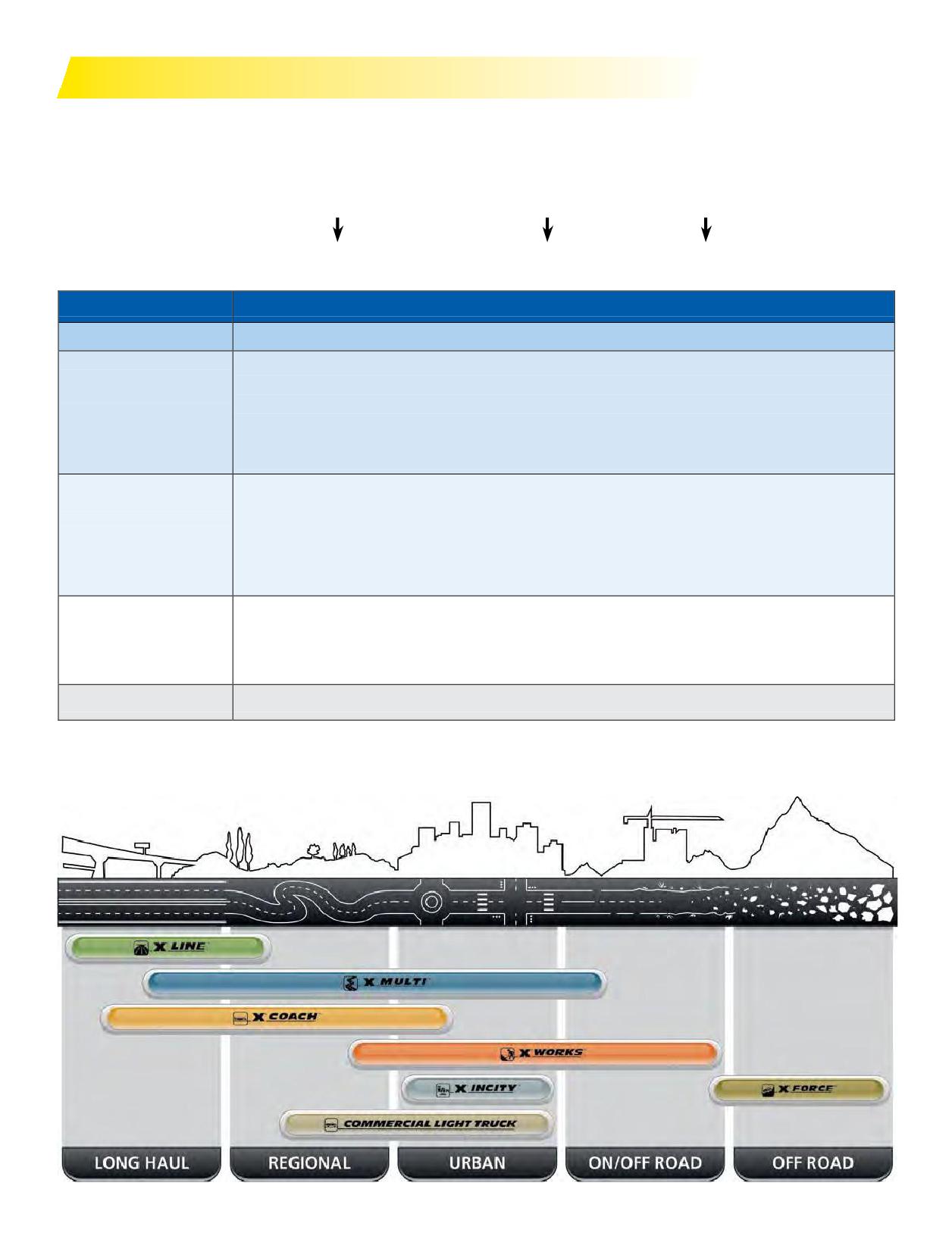
WHICH MICHELIN® TIRE?
PROPER NAMING AND SEGMENTATION
3
PROPER APPLICATION
TRUCK TIRE APPLICATION
DETERMINING MICHELIN® TIRE SIZE
6-
TREAD DESIGN
DEFINITIONS
DOT Sidewall Markings
Loads Per Axle and Inflation Pressures
Wheels
Maximum Speed Restrictions
Static And Low Speed Load and Pressure Coefficients
TRA (The Tire and Rim Association, Inc.) Standards
Technical Specifications for Michelin 455/55R22.5 LRM
on 13.00x22.5 Wheels Steer Axle, First Life Only
TRUCK TYPE BY WEIGHT CLASS
13-
Section One: Tire Selection
1
WHICH MICHELIN® TIRE?
TREAD PATTERN DESIGNATION
Michelin usesspecifi numbers orletters toidentifydifferent types of tread patterns or casing construction.
X
® MULTI
™ ENERGY D
Application
Benefit
Position
For example:
MICHELIN® Radial
X
= MICHELIN® Radial
Prefix
X One®
= Wide Single Tire Replacing 2 Traditional Duals
A
= X® LINE™
= Highway Applications
E
= X® MULTI™
= Regional Applications
Y
= X® WORKS™
=
80% On-Road Use, 20% Off-Road Use
Application*
L
= X® FORCE™
= 20% On-Road Use, 80% Off-Road Use
U
= X® INCITY™
= Urban Use
X® COACH™
= Coach and Recreational Vehicle Use
ENERGY
= Fuel Efficient
GRIP
= All Season Grip
R
= Anti-chip / Cut-resistant Compound
Benefit
M/S
= Mud and Snow
S
= Severe Service
+
= Enhanced Version
D
= Drive
T
= Trailer
Position
Z
= All Position
F
= Front (Steer)
Index
Number at the end of the designation used to denote product evolution or attributes.
* A, E, Y, L, U = Traditional Application Designations; X® LINE™, X® MULTI™, X® WORKS™, X® FORCE™, X® INCITY™, X® COACH™ = New Application Designations;
Michelin will progressively replace the traditional application designations with the new ones.
Federal Motor Carrier Safety Regulations, 9 C.F.R. § 395.75 (d), specify that “no bus shall be operated with regrooved, recapped or retreaded tires on the front wheels.”
2 Section One: Tire Selection
PRODUCT NAMING AND SEGMENTATION
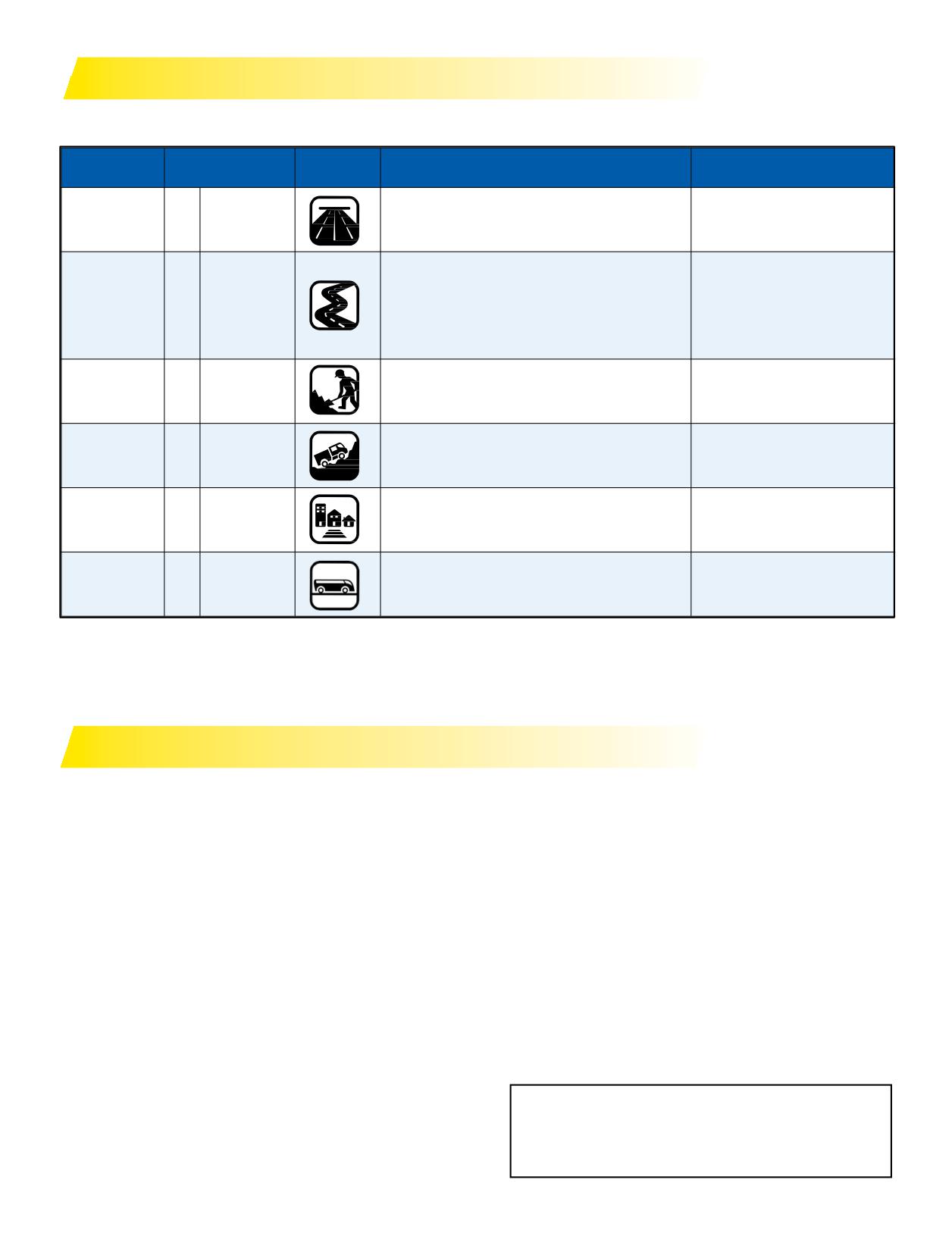
The specific tread design used should only be considered after the vehicle type and user vocation has been examined.
There are several categories of tire service applications:
APPLICATION (1)
SEGMENT
PICTOGRAMS
APPLICATIONS
VOCATIONS
NAME
Heavyloadsandhighspeedsforextended
Line Haul
A
X® LINE™
periods of time. Primarily interstate or divided
• Truckload Carrier
highway.
Regional is medium to heavy loads, frequently
on 2-lane roads. Vehicles generally return to
• LTL Dry Van
home base at night.
• Parcel
Regional
E
X® MULTI™
Emerging Super Regional application
• Food & Beverage
combines driving conditions seen in
• Pick-up & Delivery
Line Haul and Regional applications.
Heavy loads and slower speeds, operating
• Construction and Mining
On/Off Road
Y
X® WORKS™
on a mixture of improved secondary and
• Forestry and Logging
aggressive road surface.
• Oil Field
Very heavy loads normally on poor or
• Forestry and Logging
Off Road
L
X®FORCE
™
unimprovedsurfaces.(2)
• Oil Field
• Urban Buses
Stop-and-go delivery ... service within a
Urban
U
X® INCITY™
limited radius - metro and suburban.
• Sanitation and Refuse
Coach and
• Buses
X® COACH™
Coaches and recreational vehicles
• RV
Recreational
D = Drive Positions, T = Trailer Positions, Z = All-Wheel Positions
(1) A, E, Y, L, U = Traditional Application Designations. X® LINE™, X® MULTI™, X® WORKS™, X® FORCE™, X® INCITY™, X® COACH™ = New Application Designations.
Michelin will progressively replace the traditional application designations with the new ones.
(2) Off Road Tires can also be used On Road if DOT is present.
PROPER APPLICATION
URBAN TIRES:
Tires with the “Y” or “X® WORKS™”designation are for
U or X® INCITY™
applications expected to be 80% On-road use and 20%
The tires with the “U” or “INCITY” designation are
Off-road use. Theyhaveamaximumspeedof65mph.
designed and optimized for urban applications and should
Tires with the “L” or “X® FORCE™” designation are for
not be used in non-urban/suburban applications including
applications expected to be 20% On-road use and 80%
but not limited to, line haul and RV/motorhomes/coaches.
Off-road use. Some of the “L” or “X® FORCE™” designated
These aforementioned applications may subject the tires
tires have amaximumspeedof 50mphwhileothershave
tocontinuoususeoveranextendedperiodoftime. This
maximum speeds of 55, 60 and of 70 mph.
couldlead to heat build up andmay cause the tire to fail
The Tire and Rim Association (TRA) permits operating a
prematurely and/or suddenly.
65 mph rated tire at higher speeds with a reduced load and
increased inflation. No such permission is granted by TRA
ON/OFF ROAD TIRES:
for tires with speed rating rated below 65 mph.
Y or X® WORKS™ and L or X® FORCE™
The tires with “Y” or “X® WORKS™” and “L” or “X® FORCE™”
as the third character in the tread designations are designed and
optimized for on/off road applications and are speed restricted.
These tires should not be used in applications that operate the
Always refer to the MICHELIN® Truck Tire Data Book
tires continuously on highway over an extended period of time
(MWL40731) or www.michelintruck.com and match
orat speedsthatexceedthespeedratingofthetire.This could
the tire to the application when making tire selections.
lead to heat build up and cause premature or sudden tire failure.
3
Section One: Tire Selection
TRUCK TIRE APPLICATION
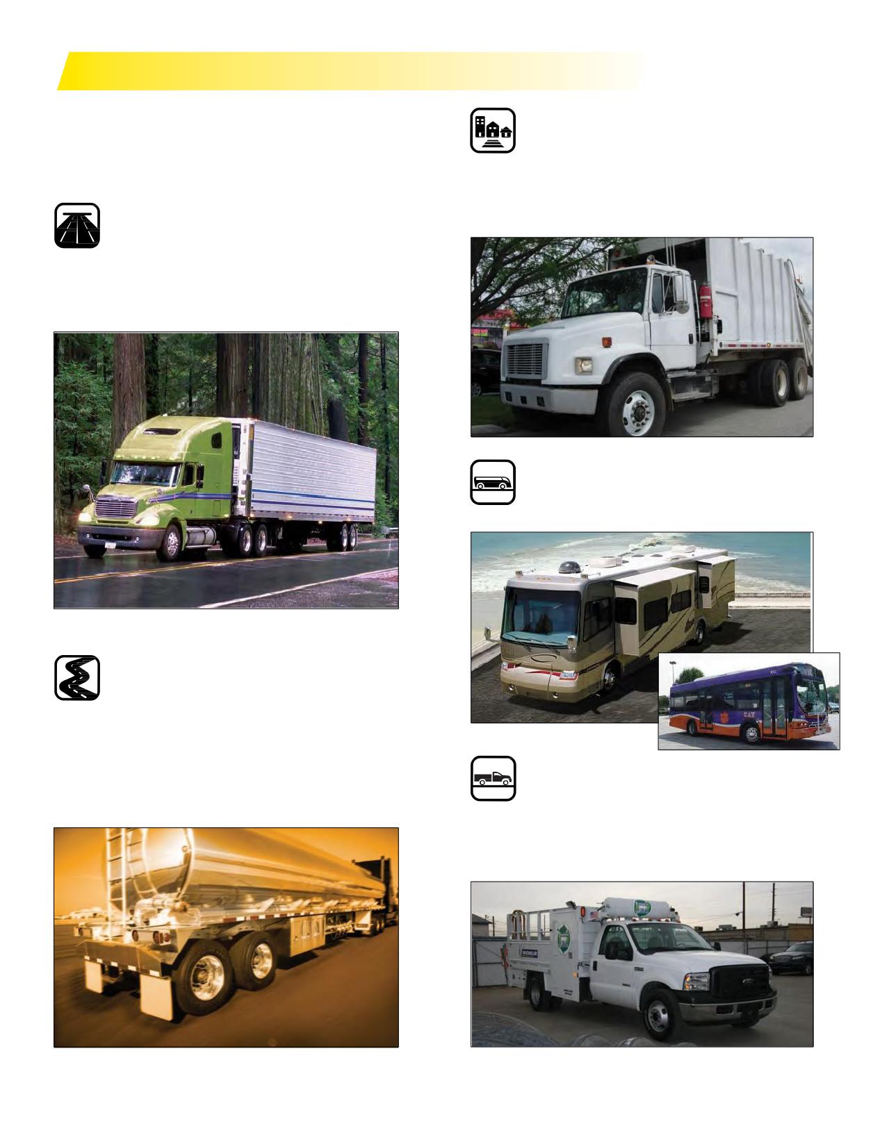
The choice of tire type depends upon the application
and wheel position. No matter what your application
Urban (U or X® INCITY™)
may be, Michelin has a tire specifically designed for you.
Urban applications are very short mileage with a high
These applications include the following:
percentage of stop and go. Primary users are in retail/
wholesale delivery, sanitation, and bus fleets. Vehicle
annual mileage - 20,000 miles to 60,000 miles.
Line Haul (A or X® LINE™)
The Line Haul application is made up of businesses
operating primarily in common carrier and lease rental
vocations. Vehicle annual mileage - 80,000 miles to
200,000 miles.
Coach and Recreational (X® COACH™)
Buses and recreational vehicles.
Regional (E or X® MULTI™)
The Regional application is made up of businesses such
as public utilities, government - federal, state, and local -
food distribution/process, manufacturing/ process,
petroleum, and schools operating within a 300-mile
radius. Vehicle annual mileage - 30,000 miles to 80,000
Commercial Light Truck Tire Applications
miles.
• Highway Tires, All-Wheel-Position
• All-Season, All-Terrain Tires
• All-Terrain Drive Axle Traction Tires
• Highway Mud & Snow Tires
4 Section One: Tire Selection
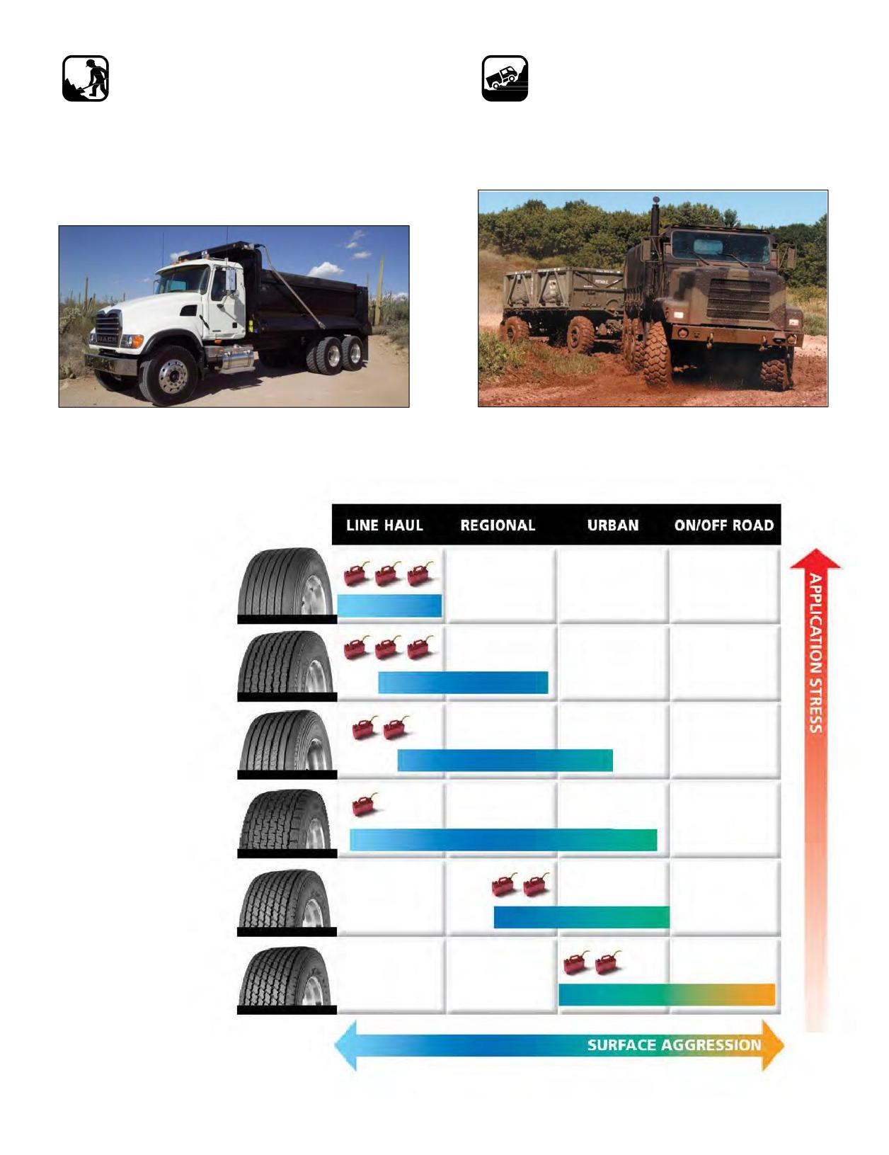
On/Off-Road (Y or X® WORKS™)
Special Tire Applications/Off-Road
On/Off Road tires are designed to provide the durability
(L or X® FORCE™)
and performance necessary in highly aggressive
• Drive & Steer
operating conditions at limited speeds. Vocations such
• Fork Lift/Utility Vehicles
as construction, mining, and refuse use these highly
• Indoor/Outdoor Applications
specialized tires. Vehicle annual mileage - 10,000 miles to
70,000 miles.
MICHELIN® X ONE® TIRE APPLICATIONS
MICHELIN®
X ONE® LINE™ ENERGY T
Fuel savings,
Weight Savings,
Even Wear, 13/32nd
MICHELIN®
X ONE® LINE™ ENERGY D
Fuel Efficient,
Long Tread Life, 24/32nd
MICHELIN®
X ONE® MULTI™ ENERGY T
High Scrub, Weight Savings,
Long Tread Life, 16/32nd
MICHELIN® X ONE® XDN®2
Long Original Life,
Weight Savings
All-Weather Traction, 27/32nd
MICHELIN® X ONE® XZU®S
High Scrub Resistance,
Weight Savings, 23/32nd
MICHELIN® X ONE® XZY®3
High Scrub Resistance,
Weight Savings, 23/32nd
Section One: Tire Selection
5
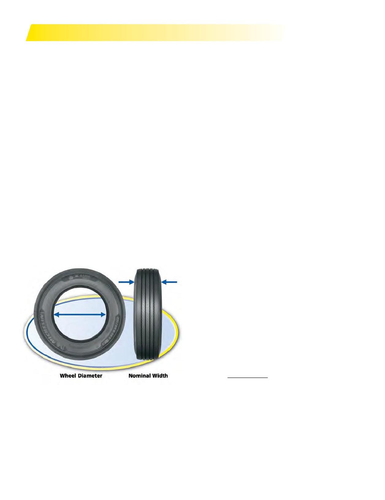
DETERMINING MICHELIN® TIRE SIZE
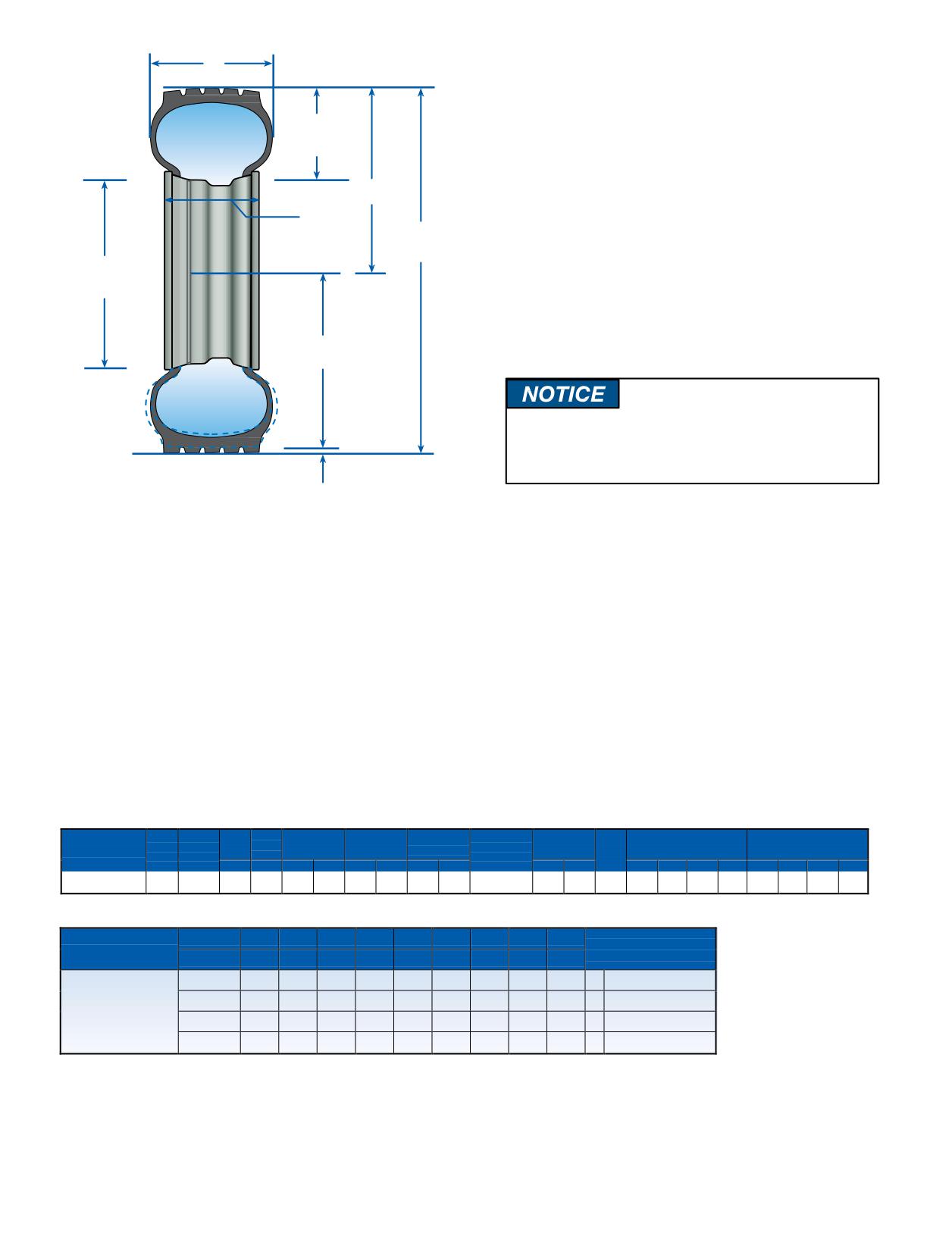
1. Tire Size: MICHELIN® radial truck tire sizes are
2. Overall Width: The maximum width (cross section)
designated by the nominal section width in inches or
of the unloaded tires including protruding side ribs and
millimeters and the wheel diameter (e.g. 11R22.5 or
decorations as measured on the preferred wheel. Overall
275/80R22.5).The“R”indicates a radial tire. Truck tire
width will change 0.1 inch (2.5 mm) for each 1/4 inch
sizes contain dimension and load index information
change in wheel width. Minimum dual spacing should
and are marked in accordance with industry standards:
be adjusted accordingly.
FMVSS (Federal Motor Vehicle Safety Standard), TRA (The
3. Nominal Wheel Diameter: Diameter of wheel seat
Tire and Rim Association, Inc.), ETRTO (European Tyre
supporting the tire bead given in nearest half-inch
and Rim Technical Organisation), and ISO (International
numbers, e.g. 22.5”.
Standardization Organization). This index indicates the
4. Overall Diameter: The diameter of the unloaded new
load capacity of the tire in single and in dual usage (e.g.
tire (measured from opposite outer tread surfaces).
144/141K). See Appendix under General Information
5. Section Height: The distance from wheel seat to outer
(Page 162) for complete ISO load index. Below are
tread surface of unloaded tire.
examples for tubeless tires. (See Section Eight,
6. Aspect Ratio: A nominal number, which represents
Pages131-142, for tube-type tire information.)
the section height, divided by the section width and
expressed as a percentage.
Example: 11R22.5
Example: Tire Size
Aspect Ratio
11
= nominal cross section in inches
11R22.5
90
R
= radial
275/80R22.5
80
22.5 = wheel diameter in inches
445/50R22.5
50
Example: 275/80R22.5 LRG 144/141K
7. Free Radius: One-half the overall diameter of the
275 = nominal cross section in mm (metric)
unloaded new tire.
80
= aspect ratio
8. Loaded Radius: The distance from the wheel axle
R
= radial
centerline to the supporting surface under a tire properly
22.5 = wheel diameter in inches
inflated for its load according to the load and inflation
LRG = load range G
tables foundin the application specific data books. See
Appendix for listing of publications under Publications,
Videos, and Websites (Page 186-187).
9. Tire Deflection: Free radius minus the loaded radius.
10. Minimum Dual Spacing: The minimum allowable
lateral distance from tire tread centerline to tire tread
centerline in a dual wheel arrangement.
11. Tire Revolutions Per Mile: Revolutions per mile
for a tire size and tread is defined as the number of
revolutions that the new tire willmake in onemile. Data
is normally presented for theloaded tire at its ratedload
and inflation in the drive position. Rolling circumference
can be calculated from the revolutions per mile as
follows:
63,360
Rolling circumference
=
Tire Revs./Mile
in inches
The tire revolutions per mile can be determined by
COMPARATIVE SIZES LOW-PROFILE -
STANDARD PROFILE
measuring (using SAE J1025) or estimated by using
MICHELIN
TRA
REPLACES
a mathematical equation. See Appendix under Tire
235/80R22.5
245/75R22.5
9R22.5
Revolutions Per Mile Calculation (Page 173). The
255/80R22.5
265/75R22.5
10R22.5
accuracy of the tire revolutions per mile number is ±1%.
275/80R22.5
295/75R22.5
11R22.5
12. Wheels: The approved/preferred wheels are designated
275/80R24.5
285/75R24.5
11R24.5
for each tire size. MICHELIN® tires should only be
mounted on the wheels shown. The wheel shown
COMPARATIVE MICHELIN® X ONE® TIRE SIZES
first is the preferred wheel. Be sure to check wheel
DUAL SIZE
MICHELIN®X ONE® TIRESIZE
11R22.5, 275/80R24.5
455/55R22.5
manufacturer’s specifications.
275/80R22.5
445/50R22.5
6 Section One: Tire Selection
2.
CHANGES TO LOAD AND INFLATION PRESSURE FOR
Overall Width
COMMERCIAL TRUCK TIRES
2003 DOT standards require that both Metric and English
5.
load, pressure, and speed units be marked on tires. In
Section
Height
order to meet this new requirement, Michelin changed its
maximum load at cold inflation pressure markings to ensure
7.
alignment with standards published by TRA (The Tire and
Free Radius
12.
Rim Association, Inc.) and ETRTO (The European Tyre and
Rim Width
4.
Rim Technical Organisation). All MICHELIN® truck tires
Overall
Diameter
manufactured after January 1, 2002 (DOT week 0102) carry
3.
L
the new markings.
Nominal Wheel
Diameter
Data books published since then reflect the changes in
maximum loads at various cold pressures. The MICHELIN®
truck tire website, www.michelintruck.com, was also
8.
updated to reflect these changes.
Loaded Radius
Always refer to the actual sidewall markings
for maximum load at cold inflation pressure
information.
9.
Deflection
Theremay still be some new or retreaded tires in use
All the information required to determine the proper tire
with the old markings. During this period of transition,
size is contained in the application specific data books.
customers may have tires with the same MSPN with
A sample is shown below.
different load and inflation markings. The guidelines below
To select the proper tire size for a vehicle, it is necessary
should be followed whenmounting tires of the same size
to know the maximum axle wheel end loads that the tires
with different markings on the same vehicle.
will carry and the maximum continuous speed at which
1. Make sure the tire maximum load and cold inflation
they will operate. Themaximumload that a tire can carryis
pressure markings do not exceed those of the wheel.
different if it is mounted in dual configuration rather than
2. If tires with different maximum load markings are mixed
single. The allowable axle loads and the required inflation
across an axle, apply the lowest load and cold pressure
pressures to carry these loads are shown in the charts for
markings to all tires.
both single and dual mountings in the MICHELIN® Truck
3. Ensure that the tire markings are adequate to meet the
Tire Data Book (MWL40731). The maximum allowable
vehicle GAWR (Gross Axle Weight Rating) for all axles.
continuous speed is also indicated.
Specifications for Tread Design: MICHELIN® X® LINE™ ENERGY Z
Tread
Max.
Loaded
Overall
Overall Width
Approved
Min. Dual
Revs
Max. Load and Pressure
Max. Load and Pressure
Load
Catalog
Speed
Wheels
Size
Depth
Radius
Diameter
(‡)
Spacing (‡) Per
Single
Dual
Range
Number
(*)
(Measuring wheel
32nds
mph
in.
mm
in.
mm
in.
mm
listed first.) in
mm
Mile
lbs.
psi
kg.
kPa
lbs.
psi
kg.
kPa
275/80R22.5 (1,2)
G
03885
19
75
18.6
473
40.1
1018
11.0
280
8.25, 7.50
12.2
311
518
6175
110
2800
760
5675
110
2575
760
275/80R22.5 LRG MICHELIN® X® LINE™ ENERGY Z
WHEEL DIAMETER
PSI
70
75
80
85
90
95
100
105
110
MAXIMUM LOAD AND
PRESSURE ON SIDEWALL
22.5”
kPa
480
520
550
590
620
660
690
720
760
LBS SINGLE
9000
9450
9880
10310
10740
11020
11560
11960
12350
S
6175 LBS AT 110 PSI
LBS DUAL
16380
17200
18160
18760
19540
20280
21040
21760
22700
D
5675 LBS AT 110 PSI
275/80R22.5 LRG
KGSINGLE
4080
4280
4480
4680
4880
5000
5240
5420
5600
S
2800 KG AT 760 kPa
KG DUAL
7440
7800
8240
8520
8880
9200
9560
9880
10300
D
2575 KG AT 760 kPa
Note: Wheel listed first is the measuring wheel.
(1) Directional tread design.
(2) 3-Retread Manufacturing Limited Casing Warranty: 3 retreads or 700,000 miles or 7 years for MICHELIN® X® LINE™ ENERGY Z tires when retreaded by an authorized
Michelin Retread Technologies (MRT) Dealer only. See limited warranty for details.
(*) Exceeding the lawful speed limit is neither recommended nor endorsed.
(‡) Overall widths will change 0.1 inch (2.5 mm) for each 1/4 inch change in wheel width. Minimum dual spacing should be adjusted accordingly.
MICHELIN® tires and tubes are subject to a continuous development program. Michelin North America, Inc. reserves the right to change product specifications at any
time without notice or obligation.
Please consult wheel manufacturer’s load and inflation limits. Never exceed wheel manufacturer’s limits without permission of component manufacturer.
Section One: Tire Selection
7
TREAD DESIGN
TREAD DESIGN
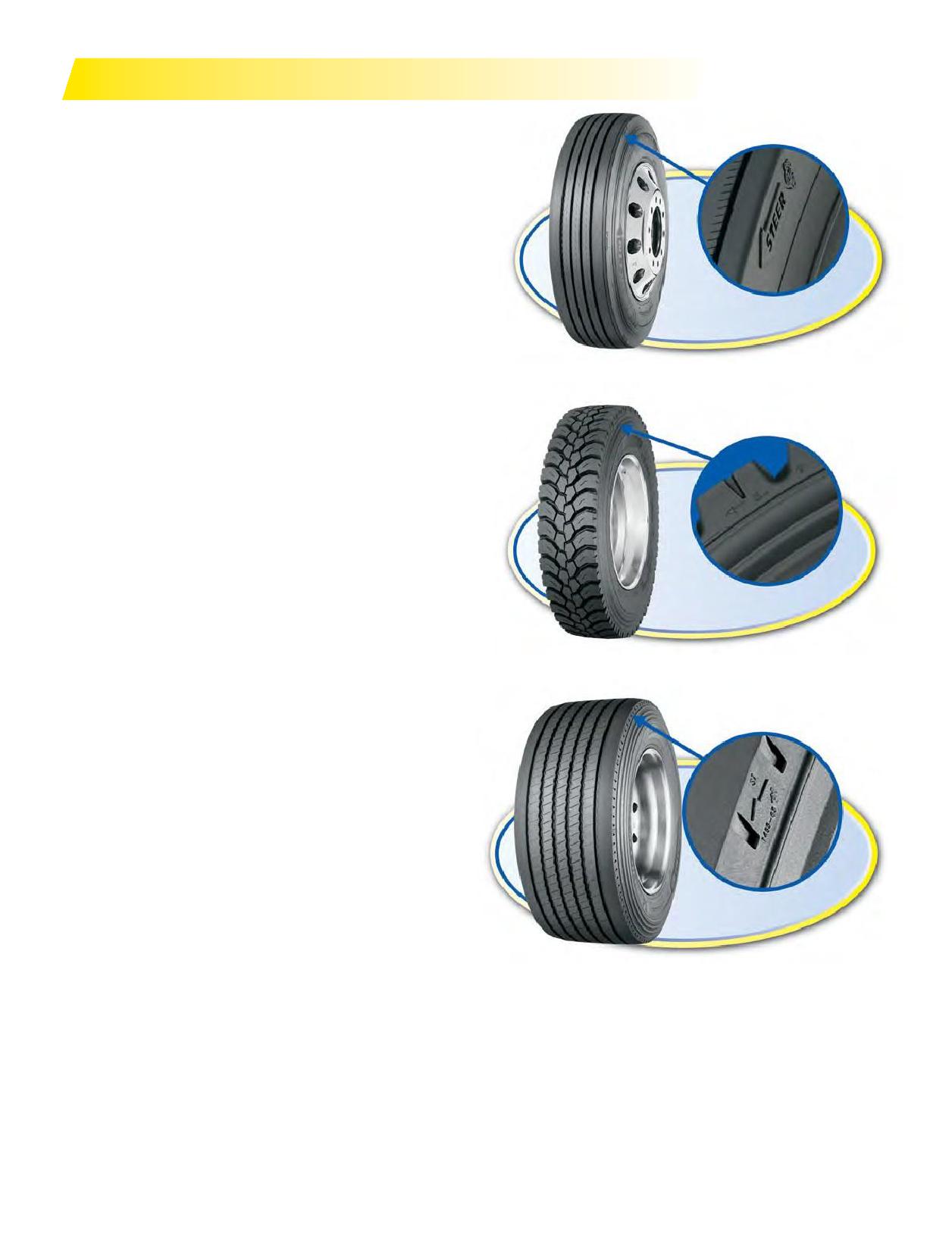
Tread designs can be categorized in two basic groups.
The proper selection of a tread design will enable the user to
maximize tread life. Selection will vary according to various
vehicle differences and/or operational conditions. Tire tread
mileage canbemaximizedorshorteneddependingonthetread
design chosen.
RIB TREAD DESIGN:
• Characterized by grooves placed parallel to the bead, thus
forming ribs, ranging in tread depths from 11/32nds to
23/32nds.
• Usually significantly better for fuel economy, although does
MICHELIN® X LINE™ ENERGY Z Steer Tire
not provide enhanced wet or snow traction.
• Usually found on the steering axle of a truck/tractor and on
other free rolling axles such as trailers, dollies, tag and pusher
axles.
• Also placed on torque axles when traction is not a high
priority.
BLOCK OR LUG TREAD DESIGN:
• Characterized by grooves placed laterally and perpendicular
to the bead, ranging from 14/32nds to 32/32nds.
• Selected primarily for traction and improved mileage.
• Usually found onthedrive or torque axle.
• The increased tread depth is needed to offset the scrubbing
and/or spinning that can occur when power is transmitted to
the drive axle.
MICHELIN® X WORKS™ XDY® Drive Tire
DIRECTIONAL TIRES
Truck tires featuring directional tread designs have arrows
moldedintotheshoulder/edgeoftheouter ribs toindicate the
intended direction of tire rotation. It is important, to maximize
tire performance, that directional tires be mounted correctly
on wheels to ensure that the directionality is respected when
mounted on the vehicle.
For example, when mounting directional drive tires on a
set of 8 wheels, use the drop centers as a reference. Four tires
should bemounted with the arrows pointing to the left of the
technician and four tires with the arrows pointing to the right.
This ensures that when the assemblies are fitted onto the
vehicle that all tires can be pointed in the desired direction of
rotation.
MICHELIN® X ONE® MULTI™ ENERGY T Trailer Tire
Directional steer tires should be mounted in a similar fashion,
one each direction, to ensure both are pointed forward.
Once directional tires are worn greater than 50%, there is
Due to constant innovation and development,
generally no negative effect of running them in a direction
the types and sizes of MICHELIN® tires are always
opposite to the indicated direction of rotation.
changing. For the most current product offerings,
Operatingdirectional tires from new to 50% worninthe
please also refer to the product line brochures, the price
opposite direction of that indicated on the tire will result in the
lists, the applications data books, and the websites:
premature onset of irregular wear, excessive noise levels, and
significantly reduced tread life.
8 Section One: Tire Selection
DEFINITIONS
DOT SIDEWALL MARKINGS
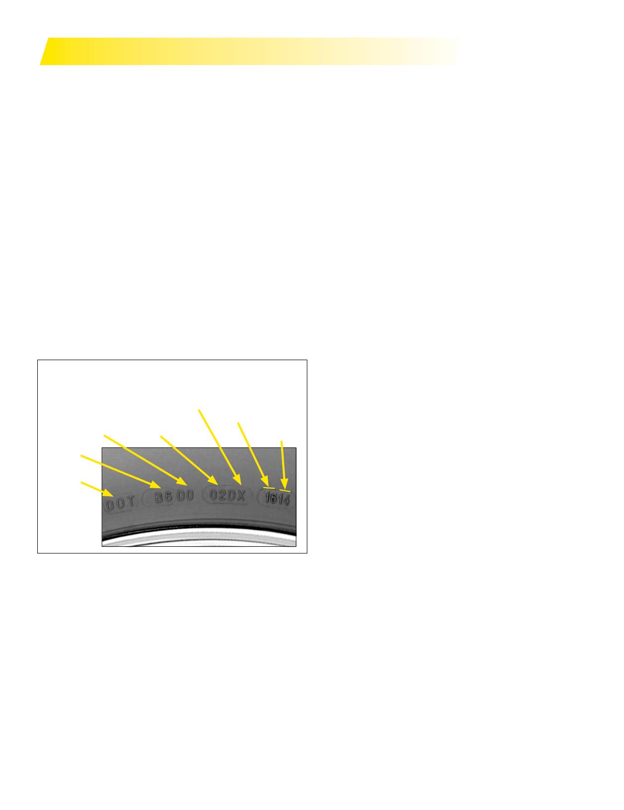
All trucks should be weighed, fully loaded, on a scale (not
All new tires sold in North America for use on Public
to exceed the GAWR - Gross Axle Weight Rating). Each axle,
Highways must have a DOT (Department of Transportation)
front and rear, must be weighed separately. Actual gross axle
numbermolded into the lower sidewall. Thiscertifies
weights should be compared with the load and inflation
compliance with Federal Regulations. All retreaded tires
tables to determine the inflation pressure required. The load
mustalsohave anadditional DOT numberaffixed to their
carried by each individual front axle tire should be noted.
sidewalls as well. It is recommended that this marking be
Due to uneven loading, motorhomes should be weighed
placed in the lower sidewall near the original DOT code.
by wheel end. The inflation pressure recommended must
Certain states may require labeling in addition to the Federal
be capable of supporting the weighed values. Therefore, the
regulations certifying compliance with the Industry Standard
maximumwheelendweightfortheaxlemustbeused.The
for Retreading. The first 2 characters on an original tire code
maximum axle weight is determined by taking the highest
indicate the factory that manufactured the tire while the first
wheel end value and multiplying by 2 for single applications
4 letters on a retread indicate the dealer who manufactured
and 4 for dual applications.
the retread. Production dates areindicated by the last 3 or
If themaximumload-carrying capacity of the tire is below
4 digits of this marking. Tires made or retreaded prior to
the actual scale weight, then tires with greater carrying
the year 2000 used 3 digits, the first two numbers indicating
capacity should be used. This means either a tire with a
the week and the last one indicating the year of production,
higherload rangeor ply rating, or a larger tire size.
followed by a solid triangle toindicate the 1990’s. Tiresmade
If the maximum load can be carried by the minimum
or retreaded after the year 1999 will have a 4 digit code: the
pressure (as listed on the Load Inflation Chart), then
a smaller size tire or a lower ply rated tire should be
first 2 indicate the week and the last 2 indicate the year of
manufacture.
considered depending on the application and operation of
the vehicle.
Example: DOT B6 D0 02D X 1614
Never reduce tire pressure below minimum data book
Newtiremarkings required by the DOT (Departmentof
specification without consulting Michelin.
Transportation):
Ambient temperature will affect the pressure within the
MICHELIN
Week
tire. For every 10-degree temperature change, pressure
Produced
Optional
Dimensional Code
Year
readings will change between 1 and 2 pounds per square
Code for Size
(Sculpture)
Produced
inch (psi). Consider this when checking pressures. Check
Plant Code
all tires when cold at least 3 hours after the vehicle has
stopped. Never bleed tire pressure from hot tires.
Identification
Additionally, altitude can have a slight affect on pressure.
For every 1,000 foot increase in altitude above sea level,
pressure will increase approximately 1/2 psi. For example, a
tire inflated to 100 psi at sealevel will read slightly over 102
psi in Denver, Colorado.
See Cold Climate Pressure Correction Data (Page 169) or
consult with Michelin for additional information on cold
LOADS PER AXLE AND INFLATION
and hot climate corrections.
PRESSURES
The carrying capacity of each tire size is tabulated for
WHEELS
various inflation pressures by individual tire load and
The correct wheels for each tire size are indicated in the
byaxle load for single applications(2 tires) and dual
specification tables. For complete tire specifications, refer to
applications (4 tires). Due to the effects of load distribution
application specific data books.
and road inclination, the four tires in dual may not equally
share the axle load. Therefore, to protect the tire carrying
MAXIMUM SPEED RESTRICTIONS*
the largest share of the load, the capacity for duals is not
Truck tires should normally be inflated according to the
twice the capacity for a single formation, but is usually
specification tables. The carrying capacities and inflation
between 5 and 13% less depending on tire size. Ensure that
pressures specified in these tables are determined with
the pressure between the dual tires and/or tires on the same
the tire’s rated maximum speed in consideration. (See
axle does not differ bymore than 5 psi. Also ensure tires run
specification tables for each tire’s rated speed in the current
in dual are within 1/4 inch diameter to help achieve equal
MICHELIN® Truck Tire Data Book - MWL40731.) This is a
loading.
maximum continuous speed, not an absolute upper limit.
Section One: Tire Selection
9
Reducing the maximum speed at which the tire will
Tires with the “Y” designation are for applications
operate and adjusting inflation pressures according to
expected to be 80% on-road use and 20% off-road use.
the information contained in the following chart can help
They have amaximum speedof 65mph*.Tires with the
increase the carrying capacity. To use the Low Speed and
“L” designation are for applications expected to be 20%
Static Coefficient Chart (Page 11) you must know the tire
on-road use and 80% off-road use.
size (standard conventional size example - 11R22.5 or
Someof the “L” designated tires have amaximum
low profile 275/80R22.5) and the maximum speed rating
speedof 50mphwhileothers havemaximum speedsof
of that tire. Speed ratings can be found in the data book
55, 60, and 70 mph*. There is no speed restriction once
or www.michelintruck.com. Based on the size and speed
the casing hasbeen retreadedper the USTMA (U.S. Tire
rating, select the correct quadrant(Table A or B), find the
Manufacturers Association) and the TMC (Technology &
speed value desired, and multiply the tire load capacity
Maintenance Council).
by the coefficient provided. Also, add the listed increase
The Tire and Rim Association, Inc. (TRA) permits
in pressure (if any) to the pressure value for the selected
operatinga 65mph*ratedtire athigher speeds with a
tire shown in the data book. Give special attention to the
reduced load and increased infl
No such permission is
wheel and vehicle axle ratings that may be exceeded by
granted by TRA for tires with speed ratings below 65 mph
the increases in load and pressure. Tires optimized for
highway applications have a maximum speed of 75 mph
* Exceeding the legal speed limit is neither recommended nor endorsed.
These limits apply only to Light Truck and Truck tires,
but do not include Special Application tires, tires for high
cube vans, low bed trailers, urban, and on/off-road use.
The tires with “Y” or “L” (see Page 3) as the third
character in the tread designations are designed and
optimized for on/off-road applications and are speed
restricted. These tires should not be used in applications
that operate the tires continuously on highways over
an extended period of time or at speeds that exceed the
speed rating of the tire. This could lead to heat build up
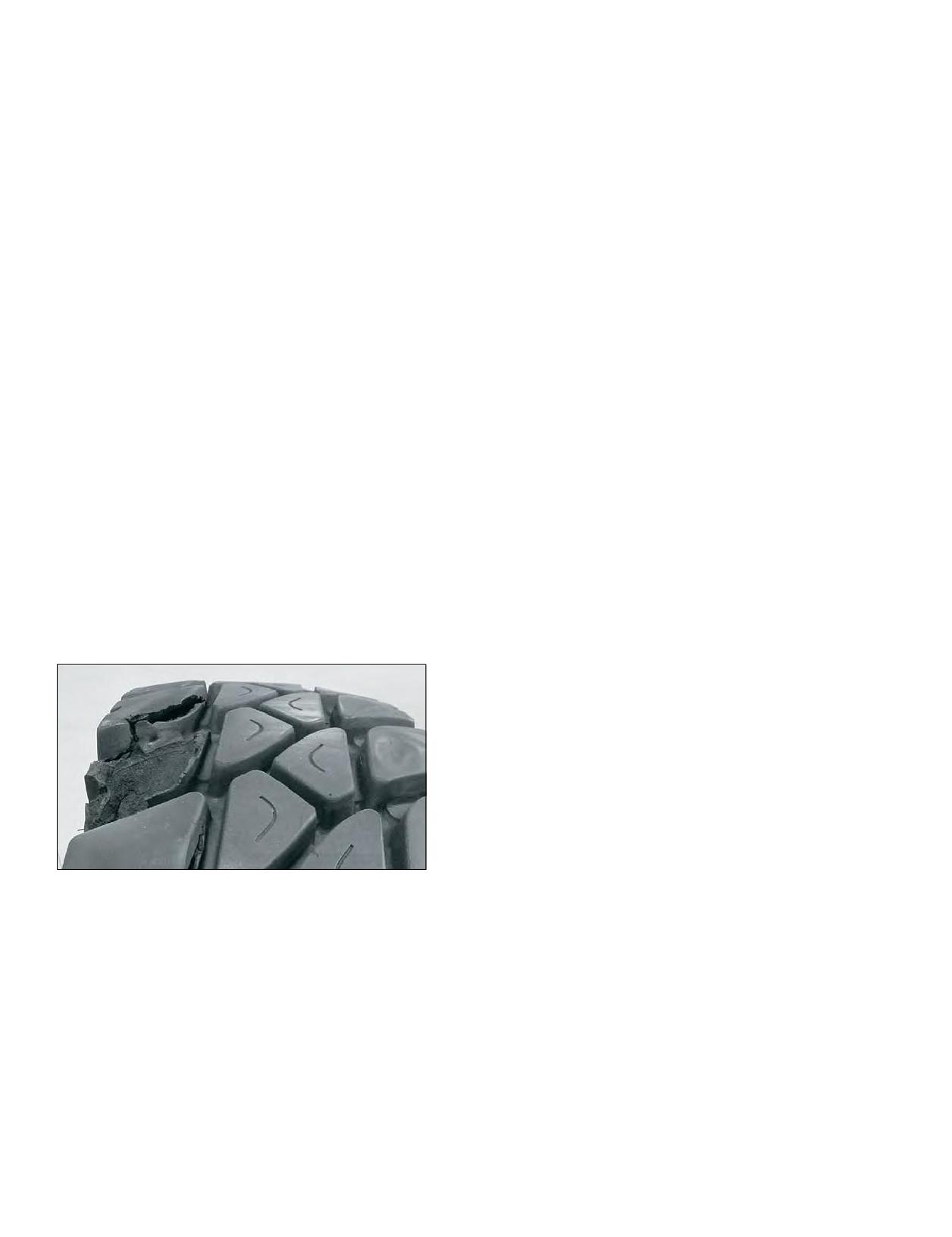
and cause premature or sudden tire failure as shown in
this photo.
Exceeding speed rating for on/off road tires may cause
premature or sudden tire failure.
10 Section One: Tire Selection

STATIC AND LOW SPEED LOAD AND PRESSURE COEFFICIENTS
Never exceed the maximum load or pressure limits of the wheel. Exceeding the wheel limits can lead to
component failure, serious accident, injury or death.
TRA (THE TIRE AND RIM ASSOCIATION, INC.) STANDARDS
(These tables apply to tires only. Consult wheel manufacturer for wheel load and inflation capacities.)
Load limits at various speeds for radial ply
(1)
truck-bus tires used on improved surfaces.
A. METRIC AND WIDE BASE TIRES
B. CONVENTIONAL TIRES
Theservice load andminimum(cold) inflationmust
Theservice load andminimum(cold) inflationmust
comply with the following limitations unless a speed
comply with the following limitations unless a speed
restriction is indicated on the tire.*
restriction is indicated on the tire.*
Speed Range
Inflation
Speed Range
Inflation
% Load Change
% Load Change
(mph)
Pressure Change
(mph)
Pressure Change
41 thru 50
+7%
No increase
41 thru 50
+9%
No increase
31 thru 40
+9%
No increase
31 thru 40
+16%
No increase
21 thru 30
+12%
+10 psi
21 thru 30
+24%
+10 psi
11 thru 20
+17%
+15 psi
11 thru 20
+32%
+15 psi
6 thru 10
+25%
+20 psi
6 thru 10 (2)
+60%
+30 psi
2.6 thru 5
+45%
+20 psi
2.6 thru 5 (2)
+85%
+30 psi
Creep thru 2.5
+55%
+20 psi
Creep thru 2.5 (2)
+115%
+30 psi
Creep (2)
+75%
+30 psi
Creep (2) (3)
+140%
+40 psi
Stationary
+105%
+30 psi
Stationary (2)
+185%
+40 psi
Note: For bias ply tires please consult the TRA Year Book.
(1) These load and inflation changes are only required when exceeding the tire manufacturer’s rated speed for the tire.
(2) Apply these increases to Dual Loads and Inflation Pressures.
(3) Creep - Motion for not over 200 feet in a 30-minute period.
Note 1:
The inflation pressures shown in the referenced tables are minimum cold pressures for the various loads listed.
Higher pressures should be used as follows:
A. When required by the above speed/load table.
B. When higher pressures are desirable to obtain improved operating performance.
For speeds above 20 mph, the combined increases of A and B should not exceed 20 psi above the inflation specified for the maximum load of the tire.
Note 2:
Load limits at various speeds for:
Tires used in highway service at restricted speed.
Mining and logging tires used in intermittent highway service
*Exceeding the legal speed limit is neither recommended or endorsed.
Section One: Tire Selection
11
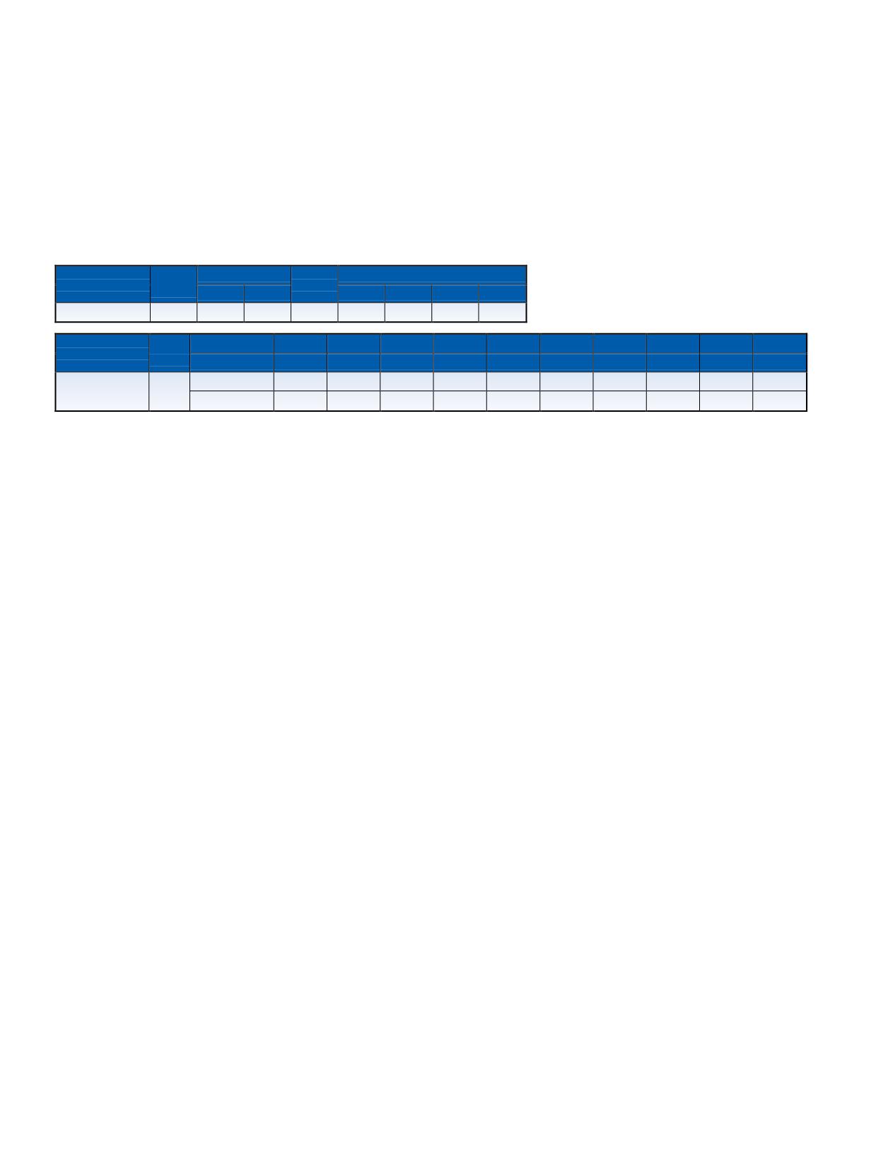
To determine the proper load/inflation table, always comply with the markings on the tire sidewall for maximum load
at cold pressure.
Load and inflation industry standards are in a constant state of change. Michelin continually updates its product information to reflect these changes.
Therefore, printed material may not reflect the current load and inflation information.
NOTE: Never exceed the wheel manufacturer’s maximum pressure limitation.
S = Single configuration - 2 tires per axle. D = Dual configuration - 4 tires per axle. Loads are indicated per axle.
TECHNICAL SPECIFICATIONS FOR MICHELIN 455/55R22.5 LRM ON 13.00x22.5 WHEELS
STEER AXLE, FIRST LIFE ONLY
Load
Loaded Radius
Max. Load Single*
Dimension
RPM
Range
in.
mm.
lbs.
psi
kg.
kPa
455/55R22.5
LRM
19.5
496
493
10000
120
4535
830
Load
psi
75
80
85
90
95
100
105
110
115
120
Dimension
Range
kPa
520
550
590
620
660
690
720
760
790
830
455/55R22.5
lbs. per axle
13740
14460
15180
15880
16600
17280
17980
18660
19340
20000
LRM
13.00” Wheel
kg. per axle
6240
6520
6900
7180
7560
7820
8100
8460
8720
9070
* Note: When used on a 13.00” wheel the max load and pressure is lower than that indicated on the sidewall.
12 Section One: Tire Selection
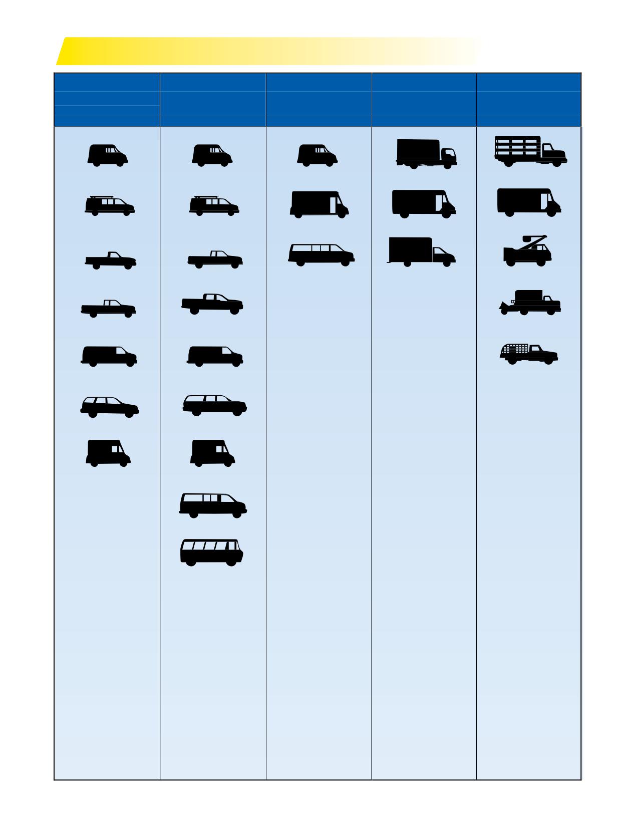
TRUCK TYPE BY WEIGHT CLASS
CLASS 1
CLASS 2
CLASS 3
CLASS 4
CLASS 5
6,000 lbs.
6,001 to 10,000 lbs.
10,001 to 14,000 lbs.
14,001 to 16,000 lbs.
16,001 to 19,500 lbs.
GVW and less
GVW
GVW
GVW
GVW
MILK/BREAD
MILK/BREAD
MILK/BREAD
CONVENTIONAL VAN
RACK
UTILITY VAN
UTILITY VAN
WALK-IN VAN
LARGE WALK-IN
LARGE WALK-IN
PICK-UP
FULL SIZE PICK-UP
LARGE VAN
CITY DELIVERY
BUCKET
FULL SIZE PICK-UP
CREW CAB PICK-UP
TREE SPECIALIST
COMPACT VAN
COMPACT VAN
BOTTLED GAS
SUV
LARGE SUV
STEP VAN
STEP VAN
CREW VAN
MINI BUS
Section One: Tire Selection
13
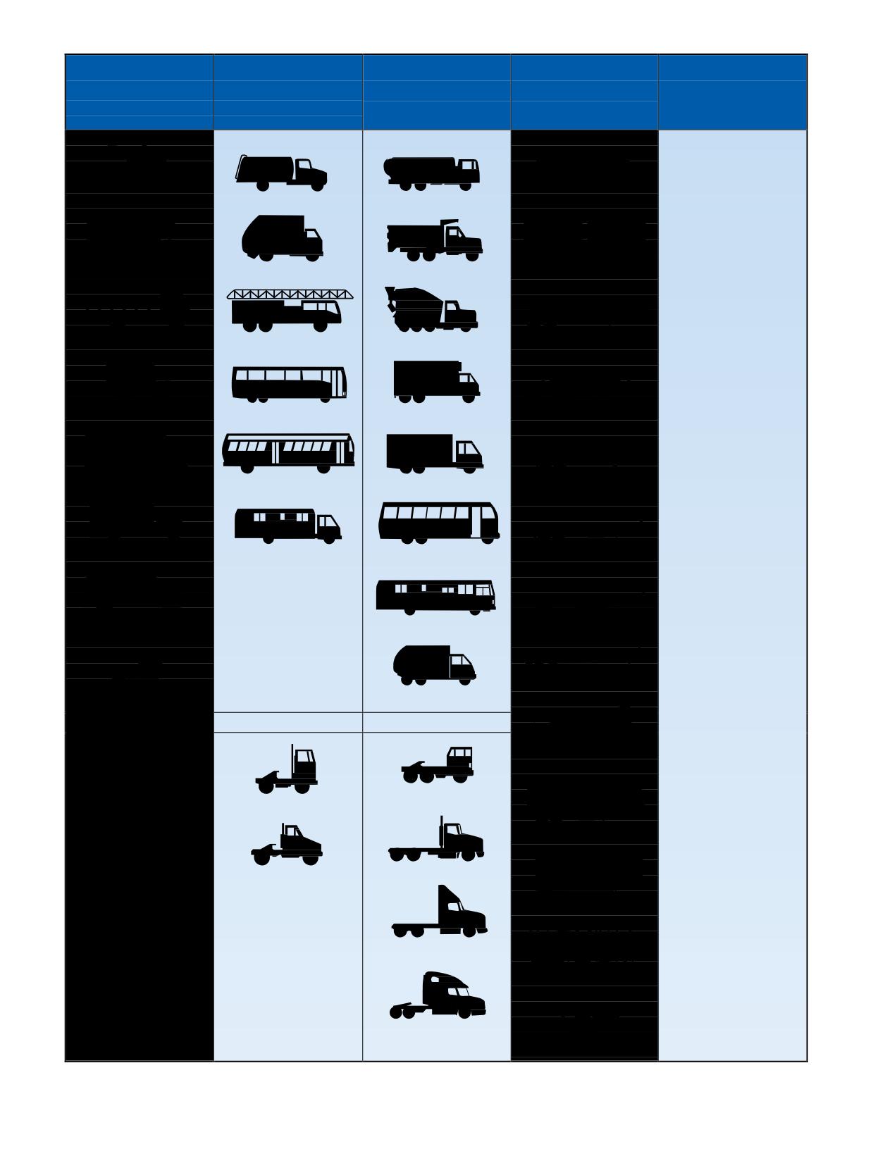
CLASS 6
CLASS 7
CLASS 8
TRAILER
NOTES
19,501 to 26,000 lbs.
26,001 to 33,000 lbs.
33,001 lbs. and over
Weight: Not specified
GVW
GVW
GVW - Gross Vehicle
Weight
The total weight of the
TOW
HOME FUEL
FUEL
DRY VAN
loaded vehicle includes
chassis, body, and
payload.
GCW - Gross
FURNITURE
TRASH
DUMP
DOUBLES
Combination Weight
Total weight of
loaded tractor-trailer
combination includes
tractor-trailer and
STAKE
FIRE ENGINE
CEMENT
LIQUID TANK
payloads.
GAWR - Gross Axle
Weight Rating
Maximum allowable
COE VAN
SIGHTSEEING BUS
REEFER
DRY BULK
load weight for a specific
spindle, axle, and wheel
combination.
Identical vehicles may
SCHOOL BUS
TRANSIT BUS
TANDEM AXLE VAN
LOGGER
appear in different
vehicle weight classes.
This is because of
a difference in the
components installed
SINGLE AXLE VAN
RV
INTERCITY BUS
PLATFORM
in each vehicle such as
engines, transmissions,
rear axles, and even
tires that are not readily
discernible in the
BOTTLER
LARGE RV
SPREAD AXLE
external appearance of
those particular vehicles.
DROP FRAME
LOW PROFILE COE
TANDEM REFUSE
GCW TO 65,000
GCW TO 80,000
DUMP
LOW PROFILE
HIGH PROFILE COE
TANDEM COE
REEFER
MEDIUM
HEAVY CONVENTIONAL
CONVENTIONAL
DEEP DROP
HEAVY TANDEM
CONVENTIONAL
AUTO TRANSPORTER
HEAVY TANDEM
CONVENTIONAL
SLEEPER
DOLLY
14 Section One: Tire Selection
SECTION TWO
Selecting the Wheel
Section Two
Selecting a Wheel
15-26
WHEEL SYSTEMS
16-21
Steel vs Aluminum
Special Considerations for Aluminum Wheels
Special Fasteners
Wheel Type
- Hub Piloted Wheels
- Stud Piloted Wheels
- Cast Spoke Wheels
Torque
Disc Wheel Installation Procedure - Recommended
Mounting Torque for Disc Wheel
SELECTING A WHEEL
22
Outset/Inset
Use of Outset Wheel with MICHELIN® X One® Tires
Drop Center
VALVE SYSTEMS
23-25
Loose and Leaky Valve Stems
Proper Fasteners for MICHELIN® X One® Tires
on Stud Piloted Wheels
WHEEL SPECIFICATIONS
26
Section Two: Selecting the Wheel
15
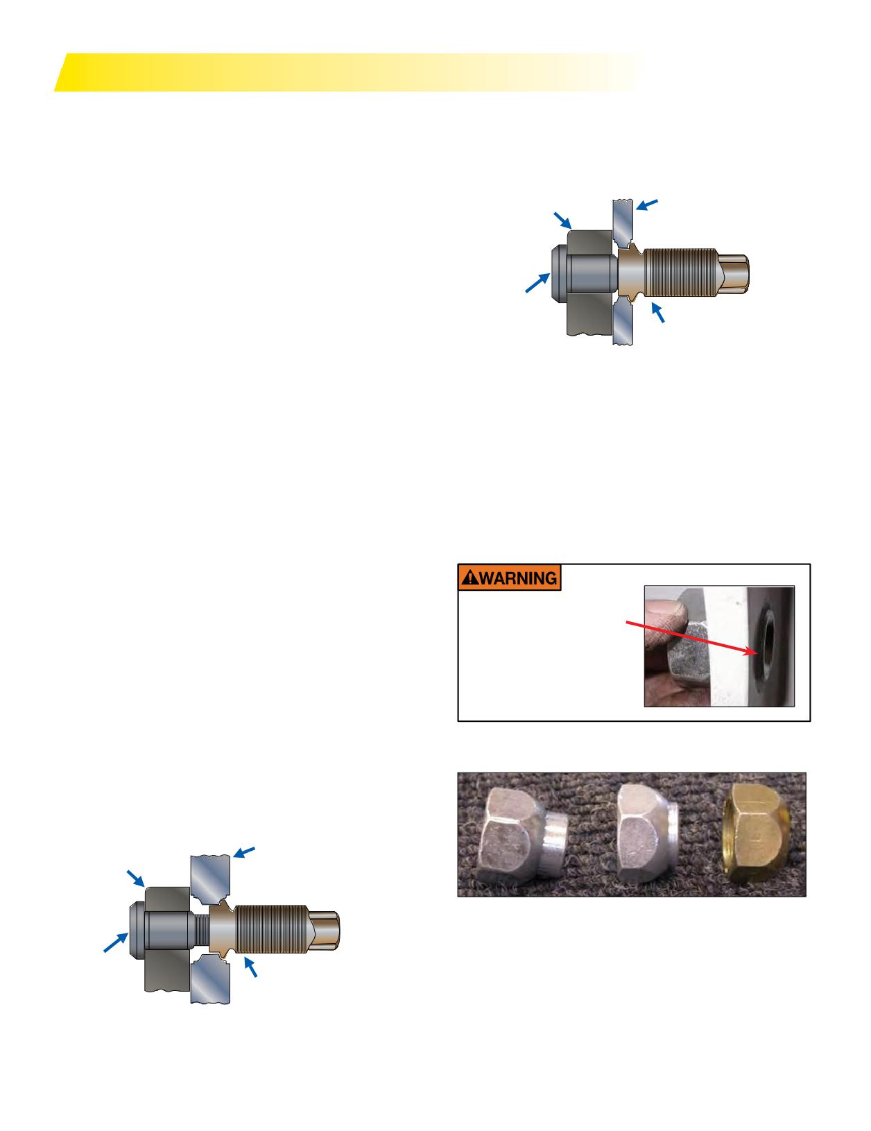
WHEEL SYSTEMS
Before servicing any truck wheel, it is essential to know
An out-of-service condition exists if the area between the
the type of mounting system you will be working on. Three
bolt hole ball seats is worn away to less than 1/16th inch
basic types of mounting systems are commonly used on
(the approximate thickness of a dime). If this is the case, the
commercial vehicles in North America. See TMC RP 217D,
wheel should be scrapped. (Figure 2)
Attaching Hardware for Disc Wheels, for more detailed
Steel Wheel
information on fasteners. Refer to Page 25 for proper
Hub
fasteners and procedures for MICHELIN® X One® tire
fitments.
STEEL VS ALUMINUM
Stud
Depending on the vehicle’s vocation, a customer may
choose steel wheels over aluminum. However, a 14.00 x
Inner Cap Nut
22.5” aluminum wheel is up to 68 lbs. lighter than its steel
counterpart. Due to the larger drop center of the aluminum
Figure 2: Incorrect
wheel, it is typically easier to mount the MICHELIN®
® tire on aluminum wheels.
X One
SPECIAL FASTENERS
It is necessary to order “cap nuts” to replace the inner
SPECIAL CONSIDERATIONS FOR
and outer nuts that are used when mounting a traditional
ALUMINUM WHEELS
stud piloted dual assembly. These parts can be ordered
It is also important to note that the disc thickness of
from a wheel distributor in your area. The part numbers
aluminum wheels is usually much thicker than steel wheels,
are listed on Page 25. A 50/50 split of left and right hand
and stud length must be checked when changing from steel
threads will be required.
wheels to aluminum wheels. Aluminum wheel disc thickness
ranges from 3/4” to 1-1/8”. This is approximately double
the thickness of steel disc wheels. Because of this increase
in disc thickness, special consideration must be given to
aluminum wheel attaching hardware. Wheel stud lengths
Do not use the 5995 nut
are specifi
designed to suit varying disc wheel mounting
on steel stud piloted
wheels, as the shoulder
systems, brake drum mounting face thickness, and disc
will protrude past the
wheel material types. Failure to use the correct length studs
disc face preventing
may lead to insuffi
clamp load of the disc wheels.
proper installation and
The minimum length for dual aluminum wheels is 1.06
safe operation.
inches or 27 mm as measured from the brake drum face
when mounted on the hub. The pilot must engage 1/2 of
the thickness of the aluminum wheel. Refer to TMC RP
217D, Attaching Hardware for Disc Wheels. Hub Bore and
15 degree bead seat measuring tools are available from the
wheel manufacturers. (Figure 1)
Aluminum Wheel
Hub
From left to right: Aluminum MICHELIN® X One® tire
fastener, steel or aluminum MICHELIN® X One® tire
fastener, and steel MICHELIN® X One® tire fastener.
See application chart on Page 25 for part numbers and
Stud
more information.
Inner Cap Nut
Figure 1: Correct
16 Section Two: Selecting the Wheel
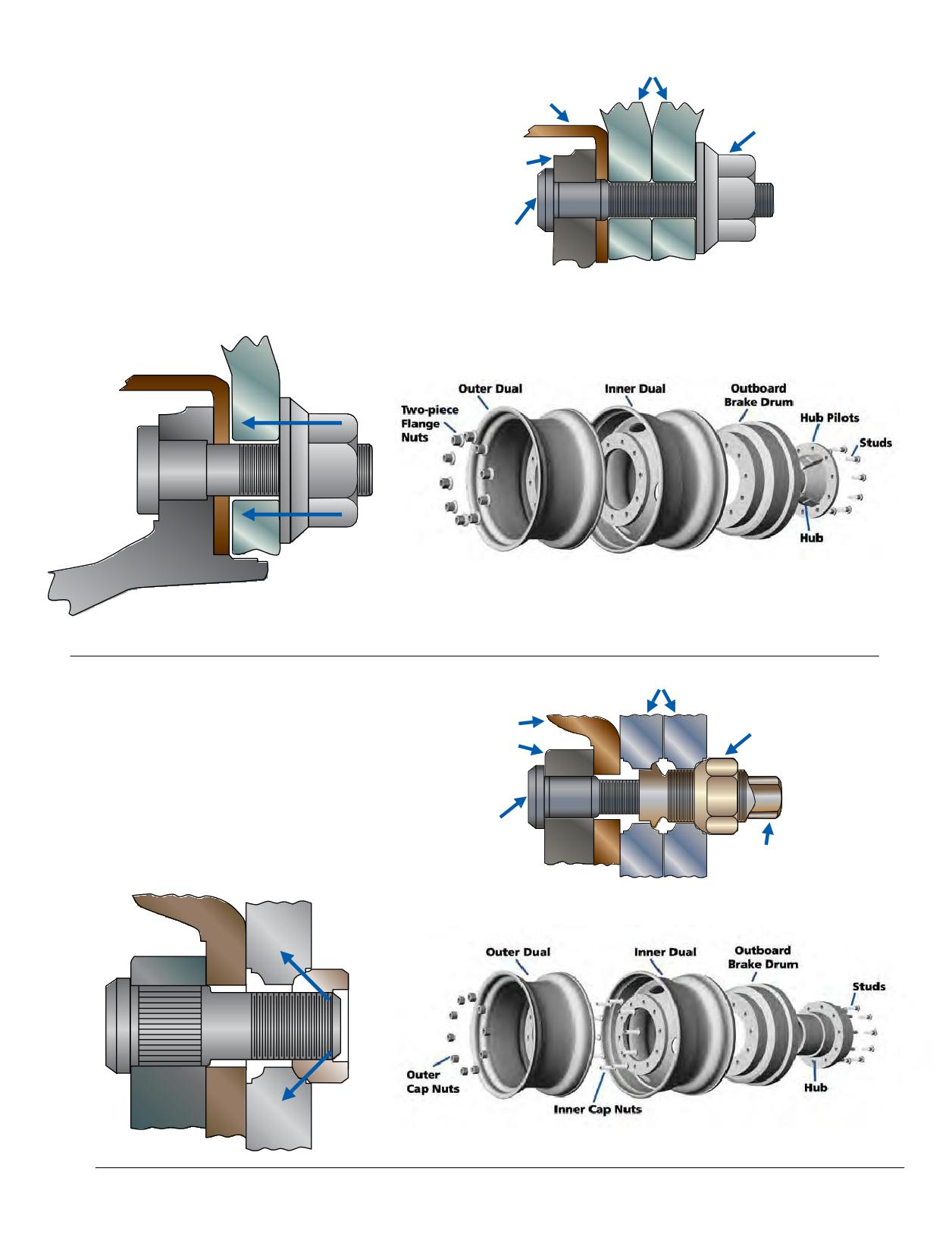
WHEEL TYPE
Hub Piloted Wheel
Hub Piloted Disc Wheels
Drum
Both aluminum and steel wheels are currently available
Two-Piece
in hub piloted configuration. Hub Piloted Disc Wheels are
Flange Nut
designed to center on the hub at the center hole or bore
of the wheel. The wheel center hole locates the wheel on
Hub
pilots built into the hub. Hub piloted wheels are used with
two-piece flange nuts, which contact the disc face around
the bolt hole. Only one nut on each stud is used to fasten
Stud
single or dual wheels to a vehicle. All stud and nut threads
are right hand. Hub piloted wheels have straight through
bolt holes with no ball seat, which provides a visual way of
identifying them.
Stud Piloted Disc Wheels
Stud Piloted Wheel
There are aluminum and steel wheels with 2” outset
currently available in stud piloted configuration. Stud
Drum
Outer Cap Nut
Piloted Disc Wheels are designed to be centered by the
Hub
nuts on the studs. The seating action of the ball seat nuts
in the ball seat bolt holes centers the wheels. Stud piloted
dual wheels require inner and outer cap nuts. Fasteners
with left hand threads are used on the left side of the
Stud
vehicle and those with right hand threads are used on the
Inner Cap Nut
right side of the vehicle.
Section Two: Selecting the Wheel
17
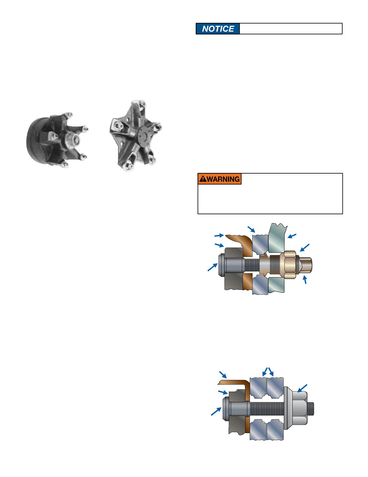
Cast Spoke Wheels
Correct components must be used.
Cast Spoke Wheels consist of a metal casting
that includes the hub with spokes, either 3, 5, or 6.
It is important to note that some hub piloted and stud
Demountable rims are attached to this axle component
piloted wheels may have the same bolt circle pattern.
with clamps. Each cast spoke wheel requires specific
Therefore, they could mistakenly be interchanged. Each
clamps designed for that wheel. The cast spoke wheel
mounting system requires its correct mating parts. It is
with brake drum and clamps for rear axles requires a
important that the proper components are used for each
spacer band to hold the two rims apart and provides for
type of mounting and that the wheels are fitted to the
proper dual spacing. Proper torque is 210-260 lb/ft.
proper hubs.
If hub piloted wheel components (hubs, wheels,
fasteners) are mixed with stud piloted wheel components,
loss of torque, broken studs, cracked wheels, and possible
wheel loss can occur since these parts are not designed to
work together.
Mixing hub piloted and stud piloted wheels will not
allow the inner cap nut to fit into the inner wheel and
will result in the inner cap nut interfering with the outer
wheel. (Figure 1)
5 Spoke
5 Spoke
Cast Spoke Wheel
Cast Spoke Wheel With Clamps,
With Brake Drum and Clamps
Without Brake Drum
Never mix components from different wheel
for Rear Axles
for Front Axles
systems. Doing so can lead to component
failure, accident, serious injury or death.
Stud Piloted Wheel
Hub Piloted Wheel
Drum
Outer Cap Nut
Hub
Stud
Inner Cap Nut
Figure 1: Improper Mounting
Ball seat, stud piloted wheels should not be used with
flange nuts because they have larger bolt holes and do
not have sufficient area near the bolt hole to support the
flange nut. Slippage may occur. Also the center hole is too
large to center the wheel. (Figure 2)
Stud Piloted Wheel
Drum
Two-Piece
Flange Nut
Hub
Stud
Figure 2: Improper Mounting
18 Section Two: Selecting the Wheel
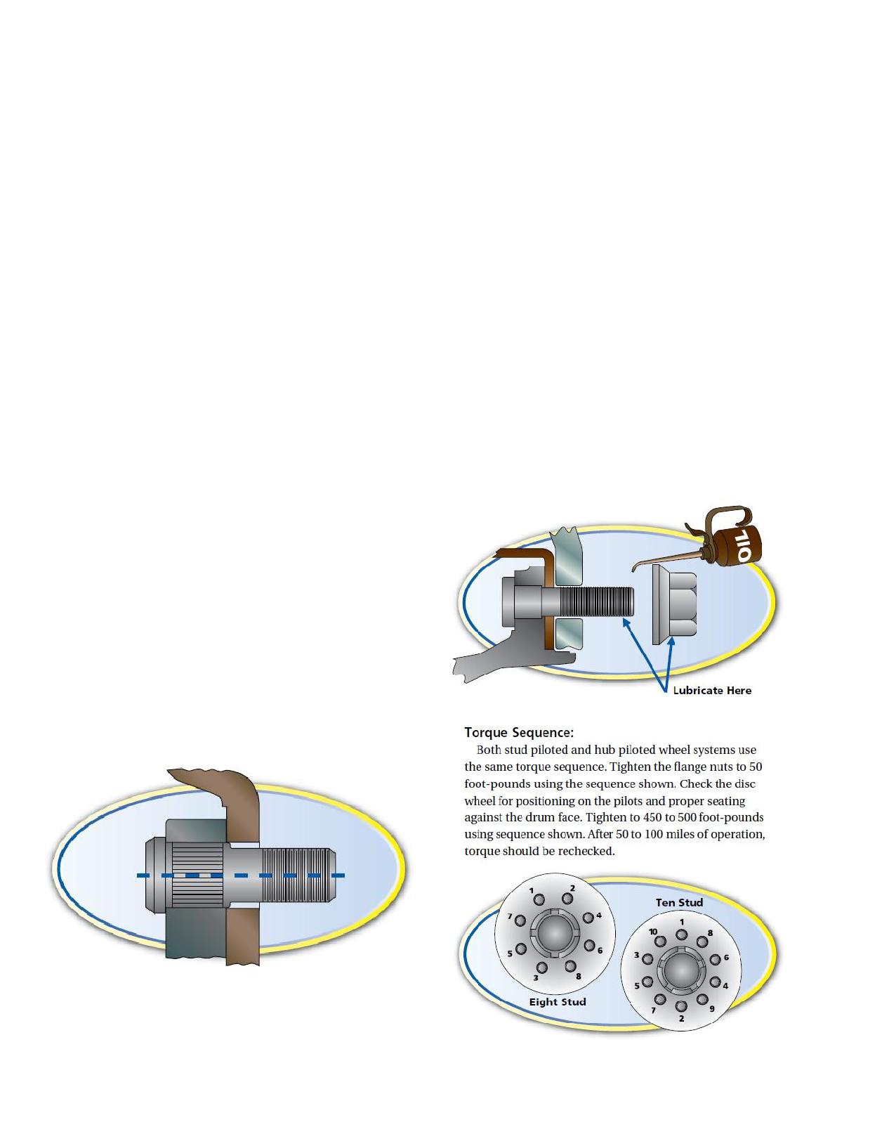
It is important to note that some hub piloted and stud
Hub piloted mounting system:
piloted wheels may have the same bolt circle pattern.
Most North American manufacturers of highway
Therefore, they could mistakenly be interchanged. Each
trucks, tractors and trailers, which incorporate the hub
mounting system requires the correct mating parts. It is
piloted wheel mounting system, require wheel studs and
important that the proper components are used for each
2-piece flange nuts with metric threads. Most frequently
type of mounting and that the wheel is fitted to the proper
these are M22 x 1.5. Before installing 2-piece flange nuts
hub.
apply 2 drops of SAE (Society of Automotive Engineers)
If hub piloted wheel components (hubs, wheels, and
30W oil to the last 2 or 3 threads at the end of each stud
fasteners) are mixed with stud piloted wheel components,
and 2 drops to a point between the nuts and flanges.
loss of torque, broken studs, cracked wheels, and possible
This will help ensure that the proper clamping force is
wheel loss can occur, which can lead to injury or death.
achieved when final torque is reached. Lubrication is not
These parts are not designed to be interchangeable. Refer
necessary with new hardware. To aid in installation and
to TMC RP 217D, Attaching Hardware for Disc Wheels, and
removal of aluminum wheels, some wheel manufacturers
TMC RP 608B, Brake Drums and Rotors.
recommend lubricating the hub bore and/or pilot pads.
NOTE: Some states and provinces have laws that dictate
Check with your wheel manufacturer for additional
sufficient thread engagement or thread engagement past
direction.
the nut body. Make sure you know the laws for the states
Note: When retrofitting a dual equipped tractor with
and provinces in which you operate and comply.
steel wheels to an aluminum wheel with MICHELIN®
X One® tire, it may be necessary to install longer studs to
TORQUE
obtain proper thread engagement of the nut. This is due
Stud piloted, ball seat mounting system:
to the aluminum wheel’s disc face being approximately
Left hand threads are used on the left side of the
1/4” thicker than two steel wheels in dual.
vehicle. Right hand threads are used on the right side of
the vehicle. Tighten the nuts to 50 foot-pounds using
the sequence shown. Check that the wheel is properly
positioned, then tighten to recommended torque using
the sequence shown. It is recommended that studs and
nuts on a stud piloted mounting system should be free
of rust and debris. They should then be torqued “dry” to
450-500 foot-pounds. After 50 to 100 miles of operation,
torque should be rechecked.
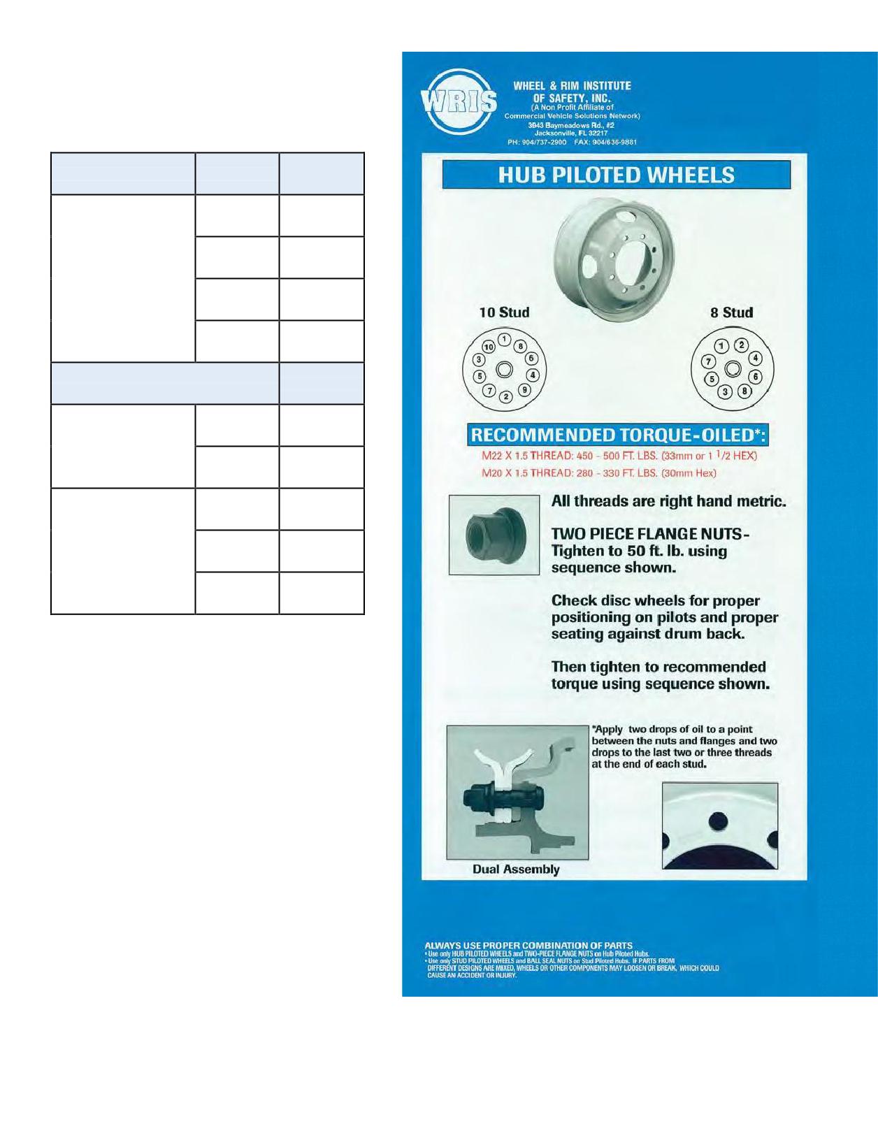
DISC WHEEL INSTALLATION
PROCEDURE-
RECOMMENDED MOUNTING TORQUE
FOR DISC WHEELS
Torque Level
Mounting Type
Nut Tread
Ft-Lb (Oiled)
11/16”-16
300-400
M20 x 1.5
280-330
Hub piloted
with flange nut
M22 x 1.5
450-500
7/8”-14
350-400
Ft-Lb (Dry)
Stud piloted,
3/4”-16
450-500
double cap nut
Standard type
1-1/8”-16
450-500
(7/8” radius)
15/16”-12
750-900
Stud piloted,
double cap nut
1-1/8”-16
750-900
Heavy duty type
(1-3/16” radius)
1-5/16”-12
750-900
Notes:
1. If using specialty fasteners, consult the
manufacturer for recommended torque levels.
2. Tightening wheel nuts to their specified torque
is extremely important. Under-tightening,
which results in loose wheels, can damage
wheels, studs, and hubs and can result in wheel
loss. Over-tightening can damage studs, nuts,
and wheels and result in loose wheels as well.
3. Regardless of the torque method used, all
torque wrenches, air wrenches and any other
tools should be calibrated periodically to ensure
the proper torque is applied.
Reprinted with permission from TMC RP 222C, User’s
Guide to Wheels and Rims, published by the Technology
& Maintenance Council (TMC) of the American Trucking
Associations, 2200 Mill Road, Alexandria, VA
22314
(703) 838-1776.
20 Section Two: Selecting the Wheel
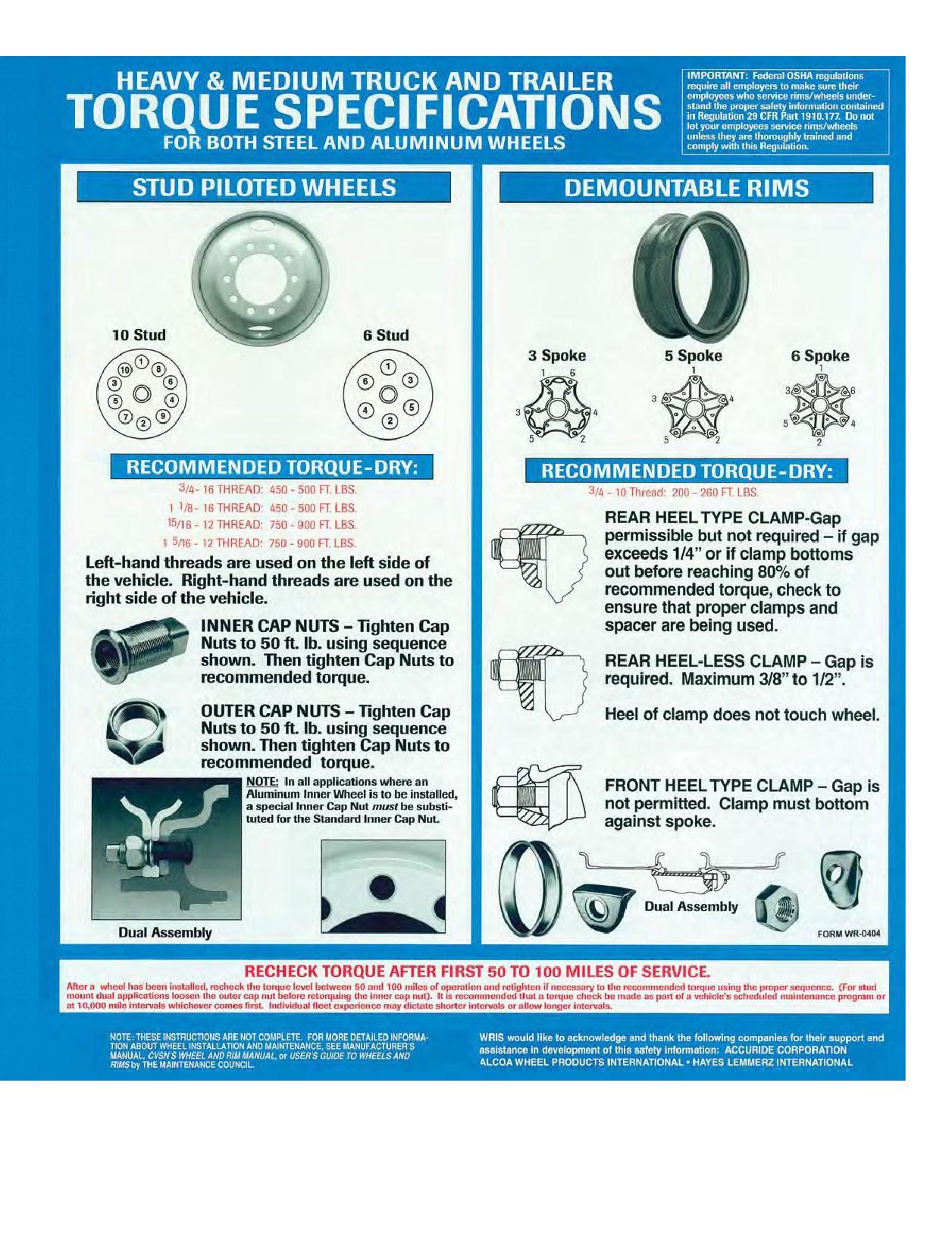
Use with permission from WRIS - Wheel & Rim institute of Safety, Inc.
Section Two: Selecting the Wheel
21
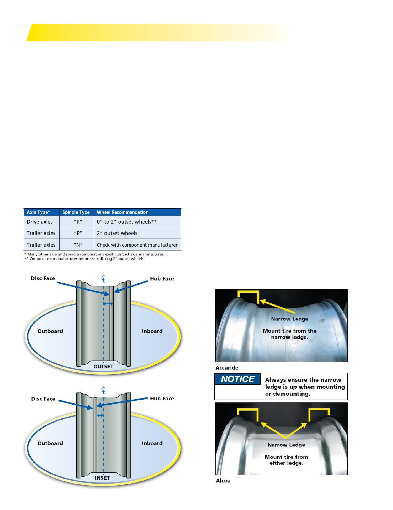
SELECTING A WHEEL
OFFSET/ INSET
Truck and trailer manufacturers may have different
specifications. For optimum track width, stability, and
Offset: The lateral distance from the wheel centerline to
payload, end-users should talk to their trailer suppliers about
the mounting surface of the disc.
the use of 83.5” axles with zero outset wheels.
Outset: Outset places the wheel centerline outboard of
the mounting (hub face) surface.
End-users that have retrofitted vehicles with 2” outset
Inset: The Inset places the wheel centerline inboard of
wheels should contact their respective vehicle, axle, or
the mounting (hub face) surface or over the axle.
component manufacturers for specific application approvals
or maintenance recommendations.
USE OF OUTSET WHEELS WITH
NOTE: Use of outset wheels may change Gross Axle
Weight Rating (GAWR). Consult vehicle and component
MICHELIN® X ONE® TIRES
manufacturer.
Some axle and hub manufacturers have recently
clarified and confirmed their position concerning the
use of such wheels with their respective components.
DROP CENTER
Historically the position of the component manufacturers
The Drop Center is the well or center portion of the wheel.
is not totally consistent, the majority view concerning
This is what allows the tire to be easily mounted on a single
the retrofit of duals with MICHELIN® X One® tires can be
piece wheel: the tire bead will “drop” into this cavity.
summarized as follows:
The 14.00 x 22.5” (15-degree bead seat) drop center tubeless
wheel required for the MICHELIN® X One® tire has differently
styled drop centers depending on the manufacturer.
Accuride® aluminum and steel wheels as well as Hayes
Lemmerz® steel wheels are produced with a narrow ledge
on one side and a long tapered ledge on the other (See Page
26). The narrow ledge is necessary to ease the mounting and
dismounting process.
The Alcoa aluminum wheel is manufactured with a narrow
ledge on either side. This allows it to be mounted and
dismounted from either side.
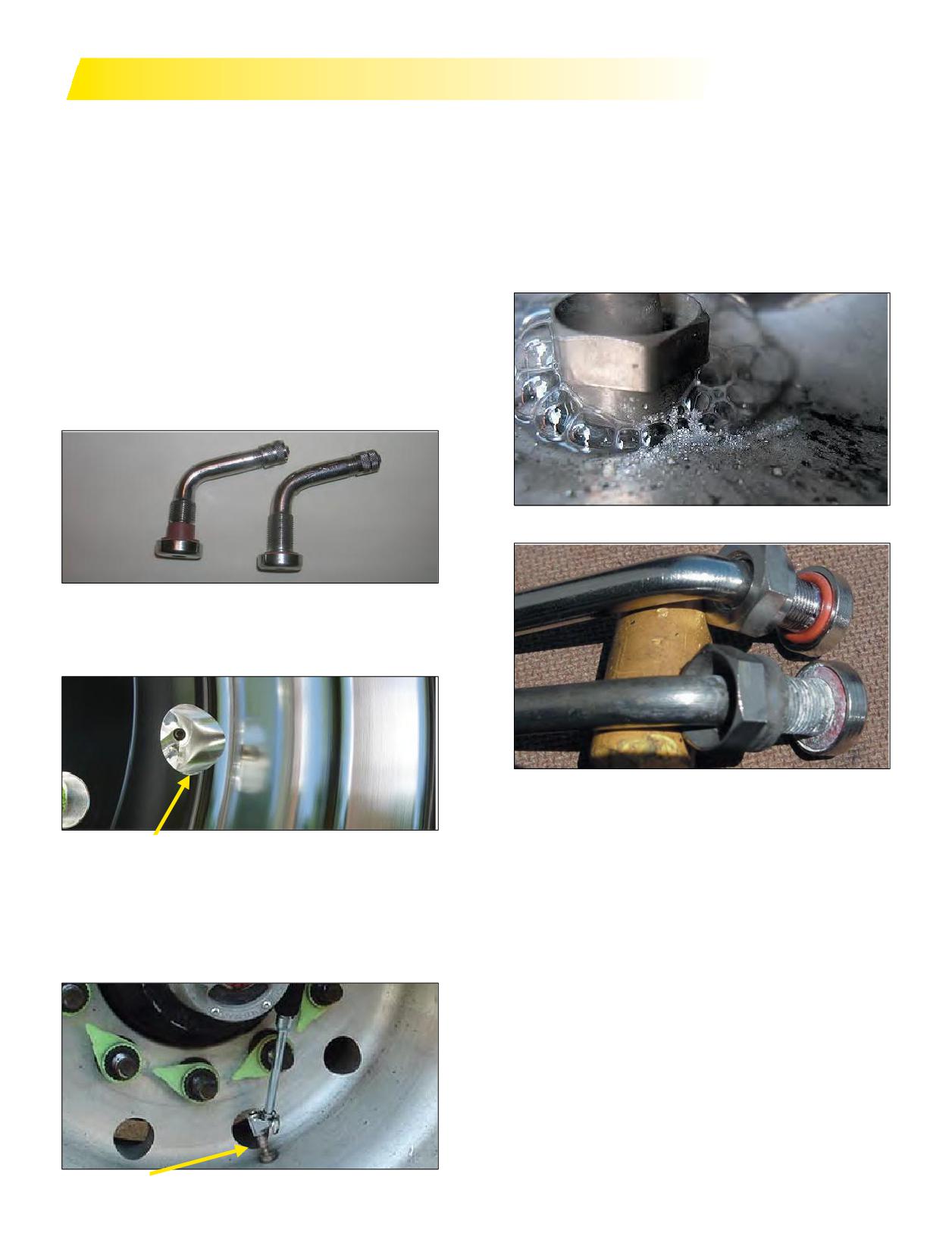
VALVE SYSTEMS
Always replace the whole valve assembly when a new
Per TMC RP 234A, Proper Valve Hardware Selection
tire is mounted.
Guidelines it is recommended that an anti-corrosive or
Ensure the valve stem is installed using the proper
dielectric compound be used on the valve stem threads
torque value: 80 to 125 in/lbs (7 to 11 ft/lbs) for aluminum
and O-rings prior to installation. This will prevent
wheels and 35 to 55 in/lbs (3 to 5 ft/lbs) for tubeless steel
corrosion from growing around the O-ring, which
wheels.
squeezes it and causes leaks. Check with your aluminum
When an aluminum wheel is used in the outset
wheel manufacturer or valve stem supplier for their
position, TR553E valve degree bend should be used.
recommendation of an anti-corrosive compound.
This valve has a 75-degree bend that facilitates taking
pressures. If the valve stem is installed on the inboard side
of the wheel, ensure proper clearance exists between the
brake drum and the valve stem. It is highly recommended
that the older style valve stems TR543E be replaced with
the newer style TR553E to minimize corrosion build-up,
thereby minimizing stem leaks.
Corrosion Related Leak at the Base of the Wheel
TR553E Valve (left) and TR543E (right)
When installed in the inset position, the longer TR545E
valve is required.
Note Corrosion On Bottom Valve
TR545E Valve
If the operator uses the wheel as a step when securing the
load, a straight TR542 valve may be preferable. An angle
head pressure gauge will be required to check pressure,
but it may still be difficult due to interference with the
hub.
TR542 Valve
Section Two: Selecting the Wheel
23
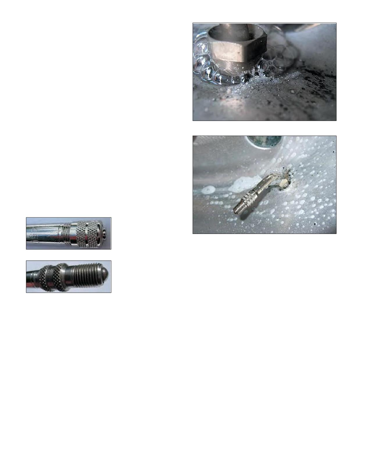
LOOSE AND LEAKY VALVE STEMS
Whether they are new or have been in use over a period
of time, valve stems can become loose. It is recommended
that you verify torque on all wheels put into service. When
installed, they should be torqued, using the proper tool at
80 to 125 in/lbs (7 to 11 ft/lbs) for aluminum wheels and
35 to 55 in/lbs (3 to 5 ft/lbs) for steel wheels.
Checking for loose and leaky valve stems should be
made a part of your regular maintenance schedule.
Methods for checking for loose valve stems:
- check by hand to see if the valve nut is loose
- spray a soapy solution on the valve to see if there
Corrosion-Related Leak at the Base of the Wheel
is a leak
- check with a torque wrench
To protect the valve from dirt and moisture, a heat
resistant metal valve cap with a rubber seal must be
installed. The number one cause of tire pressure loss in
tires can be attributed to missing valve caps.
To facilitate pressure maintenance, a dual seal metal
flow through cap may be used instead of a valve cap.
These should be installed hand tight only to prevent
damaging the seal (1.5 - 3 in/lbs).
Valve Cap With Rubber Seal
Dual Seal Metal Flow-Through Cap
24 Section Two: Selecting the Wheel
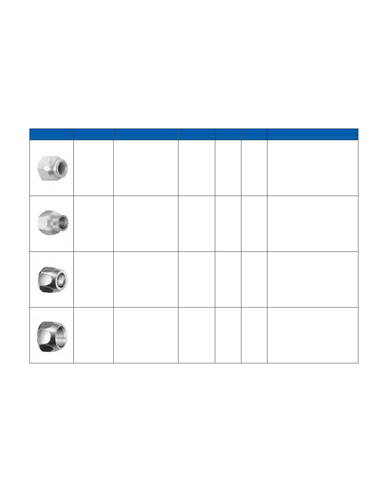
PROPER FASTENERS FOR MICHELIN® X ONE® TIRES ON STUD PILOTED WHEELS
It is important that the proper fasteners be used
is primarily for the Alcoa single mounted stud piloted
when mounting the MICHELIN® X One® tire on stud
aluminum wheel (example: 8.25 x 22.5”) and 14.00 x 22.5”
piloted wheels. If a fastener specified for the stud piloted
wide base stud piloted steel wheel. Part No. 5995R&L is
aluminum wheel is used on a steel wheel, it will bottom
for the Alcoa 14.00 x 22.5” wide base stud piloted
out on the brake drum, and the proper clamping force
aluminum wheel.
necessary to help ensure that the torque on the wheel
The last two fasteners Part No. 5652R&L for a 3/4”-16
remains constant will not be achieved, possibly resulting
studs and 5977R&L for a 1-1/8”-16 studs are specified for
in a “wheel off” situation.
the 14.00 x 22.5” stud piloted steel wheel.
In the table below, the top fastener, Part No. 5554R&L
Part No.
Replaces
Thread
Hex
High
Application and General Information
For Single Mounting of Alcoa
Alcoa 5554R&L
Forged Aluminum Disc Wheels and
5554R&L
3⁄4” - 16
11⁄2”
1”
Budd 706 13/4
Steel Stud Piloted Wide
Single Wheels.
For Alcoa Wide Base Aluminum
Alcoa 5995R&L
Wheels - “Long Grip” Cap Nut.
5995R&L
Webb 178950R
3⁄4” - 16
11⁄2”
13⁄8”
Larger height provides greater lug
178951L
wrench contact with the wheel.
Accuride NTL/NTR 25
5652R&L Zinc
Budd 37888/9 Gunite
Steel Wheel: Single Stud Mounting
Dichromate
3⁄4” - 16
11⁄2”
7⁄8”
2564/65
Front and Rear
Plating
Motor Wheel 84523/24
5977R&L
Alcoa 5977 R&L
Hardened
Accuride NTL/NTR 25
Single Large Stud Mounting Front
Zinc Yellow
11⁄8” - 16
11⁄2”
7⁄8”
Alcoa 5552R&L
and Rear
Dichromate
Budd 37891/2
Plating
NOTE: The table provided is for reference only. Wheel specific questions should be directed to the wheel manufacturer.
Section Two: Selecting the Wheel
25
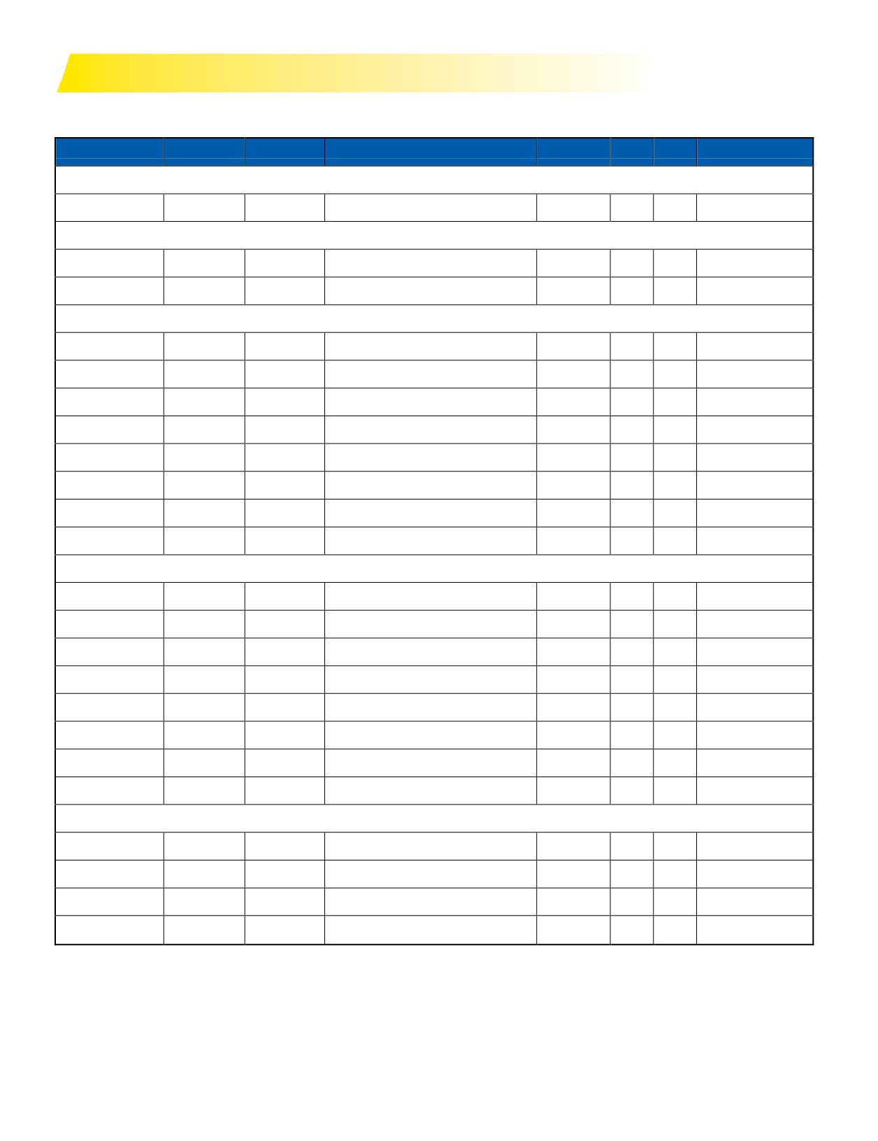
WHEEL SPECIFICATIONS
14.00 x 22.5” - 15-DEGREE DROP CENTER WHEEL SPECIFICATIONS
Manufacturer
Material
Part No.
Finish
Weight (lbs.)
Outset
Inset
Max Load & Inflation
10-hole, stud located, ball seat mounting - 11.25 in. bolt hole circle
Hayes Lemmerz
Steel
10070TW
White
125
2.00
1.49
11,000 @ 125
8-hole, hub piloted mounting - 10.827 in. bolt hole circle
Alcoa
Aluminum
841472
Polished Outside
63
2.0
N/A
12,800@130
Alcoa
Aluminum
841477
Polished
63
2.0
N/A
12,800@130
10 Hole, 2” outset, hub piloted mounting - 285.75 mm bolt hole circle
Alcoa
Aluminum
840627
Polished
58
2.0
N/A
12,800@130
Alcoa
Aluminum
840620DB
Machine Finished Dura-Bright®
58
2.0
N/A
12,800@130
Alcoa
Aluminum
840622
Polished Outside
58
2.0
N/A
12,800@130
Alcoa
Aluminum
840622DB
Polished Outside Dura-Bright®
58
2.0
N/A
12,800@130
Accuride
Aluminum
41660ANP
Machined
59
2.0
1.0
12,800@131
Accuride
Aluminum
41660XP
Polished
59
2.0
1.0
12,800@131
Accuride
Steel
29627
White
127
2.0
1.38
12,800@125
Hayes Lemmerz
Steel
10027TW
White
136
2.0
1.49
11,000@125
10 Hole, 0” outset, hub piloted mounting - 285.75 mm bolt hole circle
Alcoa*
Aluminum
840607
Polished
58
0
-1.00
12,800@130
Alcoa*
Aluminum
840600DB
Machine Finished Dura-Bright®
58
0
-1.00
12,800@130
Alcoa*
Aluminum
840602
Polished Outside
58
0
-1.00
12,800@130
Alcoa*
Aluminum
840602DB
Polished Dura-Bright®
58
0
-1.00
12,800@130
Accuride*
Aluminum
41016ANP
Machined
59
0.50
0.50
12,800@131
Accuride*
Aluminum
410160XP
Polished
59
0.50
0.50
12,800@131
Accuride*
Steel
50172
White
127
0
N/A
12,800@125
Hayes Lemmerz
Steel
10027TW
White
136
0.51
0
12,300@120
10 Hole, 1.00” outset, hub piloted mounting - 285.75 mm bolt hole circle
Alcoa
Aluminum
840601
Polished Outside
58
1.00
0
12,800@130
Alcoa
Aluminum
840601DB
Polished Outside Dura-Bright®
58
1.00
0
12,800@130
Alcoa
Aluminum
840608
Machine Finished
58
1.00
0
12,800@130
Alcoa
Aluminum
840609DB
Machine Finished Dura-Bright®
58
1.00
0
12,800@130
NOTE: Under no circumstances should a 12.25” wheel be used to fit a MICHELIN® X One® tire.
NOTE: The table provided is for reference only. Wheel specific questions should be directed to the wheel manufacturer.
*0” Outset Aluminum Wheels: Alcoa uses the mounting face as the reference.
Accuride uses the center line as the reference. This means that an Accuride 0” outset wheel is listed as 0.50” outset wheel.
Accuride at www.accuridecorp.com
Hayes Lemmerz at www.hayes-lemmerz.com
26 Section Two: Selecting the Wheel
SECTION THREE
Mounting the Tire
Section Three
Mounting the Tire
27-48
WARNINGS
28-31
Zipper Ruptures
Tire Inspection
Selection of Proper Components and Materials
Inflation Safety Recommendations
Tire and Wheel Lubrication
Preparation of Wheels and Tires
GENERAL INSTRUCTIONS FOR TUBELESS TIRE
MOUNTING/DEMOUNTING
32-33
Tubeless Tire Mounting/Demounting
Using a Mounting Machine
TUBELESS TIRE MOUNTING/DEMOUNTING
34-42
Mounting Tubeless
19.5” Aluminum Wheels
19.5” Steel Wheels
Special Tools / Mounting MICHELIN® X One® Tires
Inflation of Tubeless Tires
Demounting of Tubeless Tires
MISMOUNT
43-44
Three Easy Steps to Help Minimize Mismounted Tires
MOUNTING THE ASSEMBLY ON THE VEHICLE
45-48
Dual Spacing
Technical Considerations for Fitting Tires
Measuring Tires in Dual Assembly
Tire Mixing
Runout
Section Three: Mounting the Tire
27

WARNINGS!
IMPORTANT: BE SURE TO READ THIS SAFETY
publications for safe operating procedures in the servicing
INFORMATION.
of wheels. Please refer to OSHA Standard 29 CFR
Make sure that everyone who services tires or vehicles in
Part 1910.177 (Servicing Multi-Piece and Single Piece
your operation has read and understands these warnings.
Rim Wheels). This can be found in the Section Ten,
SERIOUS INJURY OR DEATH CAN RESULT FROM
Appendix (Pages 179-181).
FAILURE TO FOLLOW SAFETY WARNINGS.
Specifi
note that the employer shall provide a
No matter how well any tire is constructed, punctures,
program to train all employees who service wheels in the
impact damage, improper inflation, improper maintenance,
hazards involved in servicing those wheels and the safety
or service factors may cause tire failure creating a risk
proceduresto befollowed. Theemployer shall ensure that
of property damage and serious or fatal injury. Truck
noemployeeservices anywheelunlesstheemployee
operators should examine their tires frequently for snags,
has been trained and instructed in correct procedures of
bulges, excessive treadwear, separations, or cuts. If such
servicing the typeof wheel beingserviced, and shall
conditions appear, demount the tire and see a truck dealer
establish safe operating procedures for such service.
immediately.
Michelin provides the following information to further
The US Department of Labor Occupational Safety and
assist employers to comply with that initiative.
Health Administration (OSHA) provides regulations and
Tire and wheel servicing can be dangerous and
Use of starting fluid, ether, gasoline, or any other
must be done only by trained personnel using proper
flammable material to lubricate, seal, or seat the
tools and procedures. Failure to read and comply
beadsofa tubeless tire can cause the tire to explode
with all procedures may result in serious injury or
or cancausetheexplosive separation of the tire and
deathto youorothers.
wheel assembly resulting in serious injury or
death. The use of any flammable material during tire
servicing is absolutely prohibited.
Re-inflation of any type of tire and wheel assembly
that has been operated in a run-flat or underinflated
Any inflated tire mounted on a wheel contains
condition (80% or less of recommended operating
explosive energy. The use of damaged, mismatched,
pressure) can result in serious injury or death. The
or improperly assembled tire and wheel parts can
tire may be damaged on the inside and can explode
cause the assembly to burst apart with explosive
during inflation. The wheel may be worn, damaged,
force. If you are struck by an exploding tire, wheel
or dislodged and can explosively separate.
part, or the blast, you can be seriously injured or
killed.
Refer to USTMA Tire Information Service Bulletin on
potential “zipper ruptures” - TISB Volume 33, Number 6.
Re-assembly and inflation of mismatched parts can
USTMA (U.S. Tire Manufacturers Association)
result in serious injury or death. Just because parts fit
recommends that any tire suspected of having been
together does not mean that they belong together. Check
run underinflated and/or overloaded must remain in
for propermatching of all wheel parts before putting any
the safety cage, be inflated to 20 psi OVER maximum
parts together.
pressure marked on the sidewall, and then be inspected.
Do not exceed the maximum inflation pressure for the
Mismatching tire and wheel component is dangerous.
wheel.
A mismatched tire and wheel assembly may explode
and can result in serious injury or death. This warning
Be sure to reduce pressure to regular operating
applies to any combination of mismatched components
pressure before placing back in service if the tire has
and wheel combinations. Never assemble a tire and
been deemed serviceable.
wheel unless you have positively identified and correctly
matched the parts.
28 Section Three: Mounting the Tire
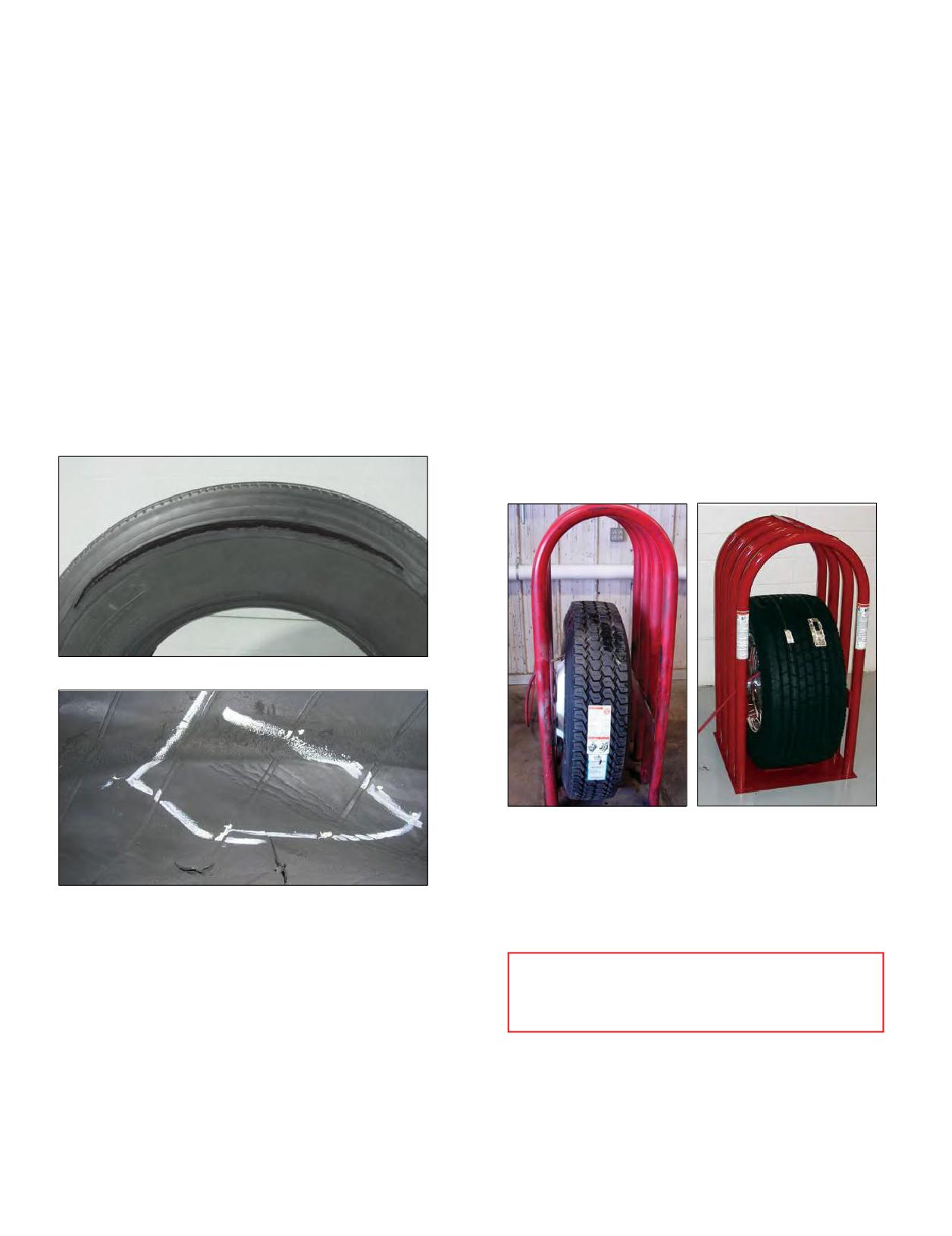
ZIPPER RUPTURES
TIRE INSPECTION
A fatigue-related damage, with or without a rupture,
Tire inspection should always include a thorough
occurs in the sidewall flex area of steel radial light, medium,
inspection of both sidewalls and inner liner, as this may
and heavy truck tires when it is subjected to excessive
reveal any potential damage condition that would cause the
flexing or heat. This zipper rupture is a spontaneous burst
tire to become scrap. Examine the inner liner for creases,
of compressed gas, and the resulting rupture can range in
wrinkling, discoloration, or insufficient repairs, and examine
length anywhere from 12 inches to 3 feet circumferentially
the exterior for signs of bumps or undulations, as well as
around the tire. This is caused by the damage and
broken cords, any of which could be potential out of service
weakening of the radial steel cables as a result of run-flat,
causes. Proper OSHA regulations must be followed when
underinflation, or overload. Eventually, the pressure
putting any tire and wheel back in service. After the tire has
becomes too great for the weakened cables to hold, and
been inflated to 20 psi in a safety cage, it should undergo
the area ruptures with tremendous force.
another sidewall inspection for distortions, undulations,
The USTMA (U.S. Tire Manufacturers Association) states
or popping noises indicating a breaking of the steel cords.
that permanent tire damage due to underinflation and/or
If this is the case, immediately fully deflate and scrap the
overloading cannot always be detected. Any tire known or
tire. If no damage is detected, continue to inflate to the
suspected of having been run at less than 80% of normal
maximum inflation pressure marked on the sidewall. Do
recommended operating pressure and/or overloaded, could
not exceed the maximum inflation pressure for the wheel.
possibly have permanent structural damage (steel cord
Any tire suspected of having been run underinflated and/or
fatigue).
overloaded must remain in the safety cage, be inflated to 20
psi OVER maximum pressure marked on the sidewall, and
then be inspected.
Zipper Rupture
Dual Cage
MICHELIN® X One® Tire Cage
Be sure to reduce tire pressure to regular operating
pressure before placing back in service if the tire has been
Inner Liner Marbling/Creasing
deemed serviceable.
The USTMA has issued a revised Tire Industry Service
Bulletin for procedures to address zipper ruptures in certain
AFTER YOU MOUNT THE
commercialvehicle tires. The purpose of the bulletinis to
MICHELIN® X ONE® TIRE ON THE WHEEL,
describe the inspection procedures for identifying potential
YOU MUST CAGE IT!
sidewall circumferential ruptures (also known as “zipper
ruptures”) on truck/bus tires and light-truck tires of steel
cord radial construction. Zipper ruptures can be extremely
hazardous to tire repair technicians. Careful adherence to
proper repair procedures is crucial.
For more information contact USTMA at info@ustires.org
or visit www.USTires.org.
Section Three: Mounting the Tire
29
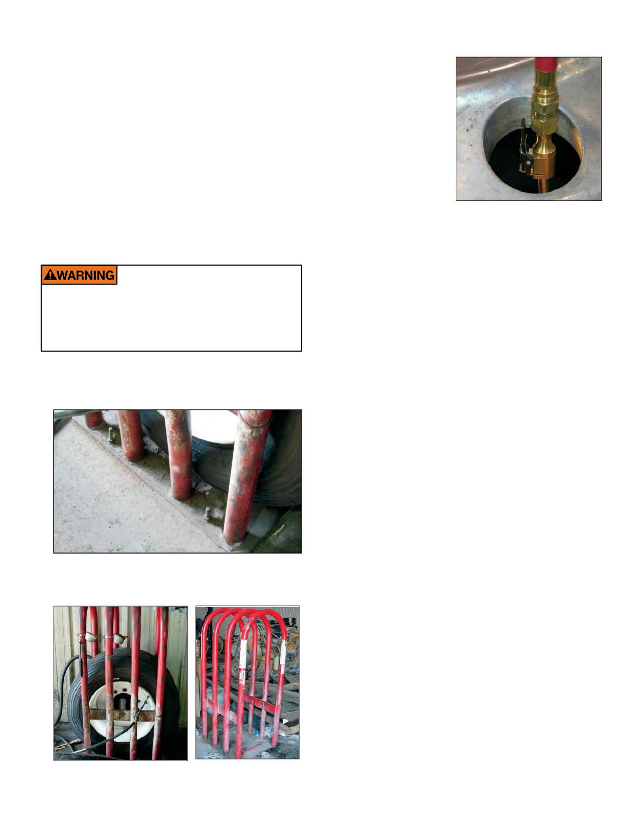
1. SELECTION OF PROPER COMPONENTS
c. Never stand over, or in front of a tire when inflating.
d. Always use a clip-on
AND MATERIALS
chuck and a sufficiently
a. All tiresmust bemounted on the proper wheel as
long air hose between
indicated in the specification tables. For complete tire
the in-line gauge and
specifications, refer to application specific data books.
the chuck to allow
b. Make certain that the wheel is proper for the tire
the service technician
dimension.
to stand outside the
c. Always install new valve cores and metal valve caps
trajectory zone when
containing plastic or rubber seals.
inflating.
d. Always replace the rubber valve stem on a 16” through
19.5” wheel.
e. Always use a safety device such as an infl
cageor
Clip-on Chuck
other restraining device that will constrain all wheel
components during the sudden release of the tire pressure
Trajectory zone means any potential path or route that
of a single piece wheel. Refer to current OSHA standards for
a wheel component may travel during an explosive
compliance.
separation or the sudden release of the tire pressure,
or an area at which the blast from a single piece wheel
It is imperative to follow all of the following
may be released. The trajectory may deviate from paths
inflation safety recommendations. Failure to do so
that are perpendicular to the assembled position of the
will negate the safety benefit of using an inflation
wheel at the time of separation or explosion. See Rubber
cage or other restraining device and can lead to
Manufacturers Association Tire Information Service
serious injury or death.
Bulletin Volume 33, Number 4 for more information.
2. INFLATION SAFETY RECOMMENDATIONS
Note: Safety cages, portable and/or permanent, are also
a. Do not bolt the inflation cage to the floor nor add any
available for inflation of the MICHELIN® X One® tire
other restraints or accessories.
assemblies.
b. The inflation cage should be placed at least 3 feet from
anything, including a wall.
30 Section Three: Mounting the Tire
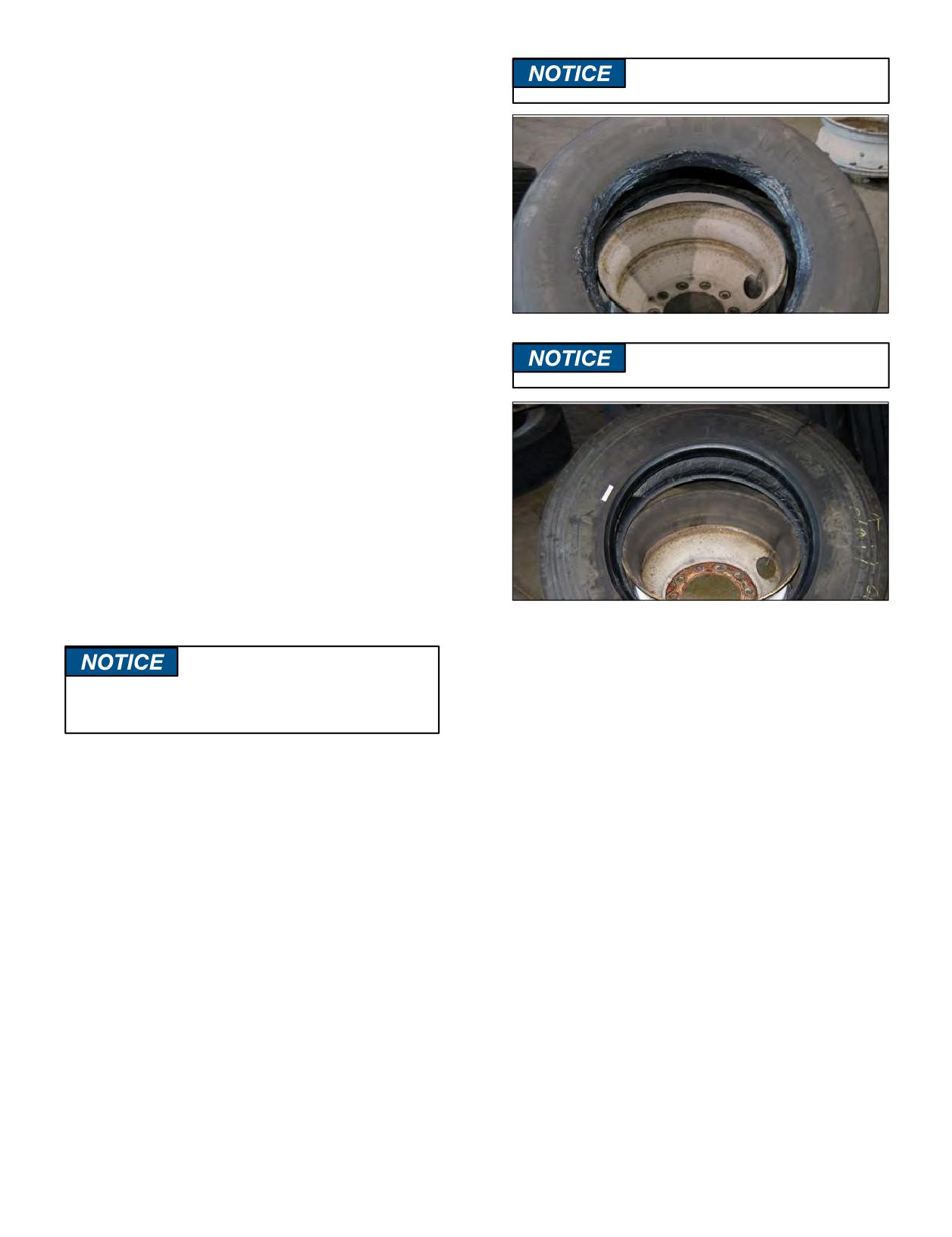
3. TIRE AND WHEEL LUBRICATION
Avoid using excessive amounts of
It is essential that an approved tire mounting lubricant
lubricants.
be used. Preferred materials for use as bead lubricants are
vegetable based and mixed with proper water ratios per
manufacturer’s instructions. Never use antifreeze, silicones,
or petroleum-base lubricants as this will damage the rubber.
Lubricants not mixed to the manufacturer’s specifications
may have a harmful effect on the tire and wheel.
The lubricant serves the following three purposes:
• Helpsminimize the possibility of damage to the tire beads
from the mounting tools.
• Helps ease the insertion of the tire onto the wheel by
lubricating all contacting surfaces.
• Assists proper bead seating (tire and wheel centering) and
helps to prevent eccentric mountings.
Dry mounting should be avoided.
Use approved lubricants.
The Michelin product, Tiger Grease 80, MSPN 25817,
is specifically formulated for commercial truck tire mounting.
It can be obtained through any authorized Michelin Truck
Tire dealer or by contacting Michelin Consumer Care
(1-888-622-2306).
Apply a clean lubricant to all portions of the tire bead
area and the exposed portion of the flap using sufficient but
sparing quantities of lubricant. Also, lubricate the entire
rim surface of the wheel. Avoid using excessive amounts of
lubricant, which can become trapped between the tire and
tube and can result in tube damage and rapid tire pressure
loss.
4. PREPARATION OF WHEELS AND TIRES
a. Always wear safety goggles or face shields when
buffing or grinding wheels.
It is important that tire lubricant be clean and free
b. Inspect wheel assemblies for cracks, distortion, and
of dirt, sand, metal shavings, or other hard particles.
deformation of flanges. Using a file and/or emery
cloth, smooth all burrs, welds, dents, etc. that are
The following practice is recommended:
present on the tire side of the wheel. Inspect the
a. Use a fresh supply of tire lubricant each day, drawing from
condition of bolt holes on the wheels. Rim flange
a clean supply source and placing the lubricant in a clean
gauges and ball tapes are available for measuring wear
portable container.
and circumference of aluminum wheels. For all wheel
b. Provide a cover for the portable container and/or other
types, also refer to the inspection, repair, and other
means to prevent contamination of the lubricant when
requirements from the wheel manufacturer.
not in use. For lubricants in solution, we suggest the
c. Remove rust with a wire brush and apply a rust
following method that has proven to be successful in
inhibiting paint on steel wheels. The maximum paint
helping to minimize contamination and prevent excess
thickness is 0.0035” (3.5 mils) on the disc face of the
lubricant from entering the tire casing: provide a special
wheel.
cover for the portable container that has a funnel-like
d. Remove any accumulation of rubber or grease that
device attached. The small opening of the funnel should
might be stuck to the tire, being careful not to damage
besized so that whenaswabisinsertedthroughthe
it. Wipe the beads down with a dry rag.
opening into the reserve of lubricant and then withdrawn,
the swab is compressed, removing excess lubricant.
This allows the cover to be left in place providing added
protection. Amesh false bottom in the containeris a
further protection against contaminants. The tire should
be mounted and inflated promptly before lubricant dries.
Section Three: Mounting the Tire
31
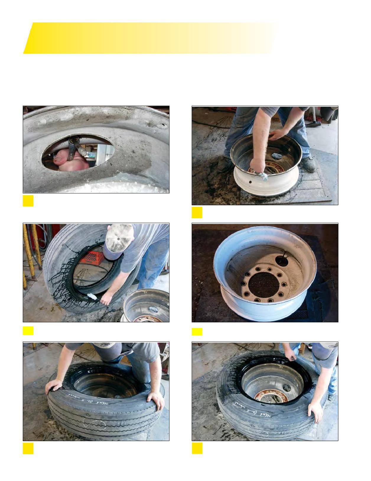
GENERAL INSTRUCTIONS
FOR TUBELESS MOUNTING/DEMOUNTING
In order for a tire to perform properly, it must be mounted on the correct size wheel. The following are general instructions
for mounting and demounting Michelin tubeless tires, including the MICHELIN® X One® tires.
Specifics for 19.5” wheels are detailed in the Mounting Tubeless Tire section (Pages 34-36). For additional detailed
instructions on mounting and demounting truck tires on particular types of wheels, refer to the instructions of the wheel
manufacturer or the RMA wall charts.
Inspect rim for excessive wear or damage. Correctly
1
position and properly torque the valve stem: 80-125
in/lbs (7-11 ft/lbs) for standard aluminum wheels and
Fully lubricate both flanges and the drop center.
2
35-55 in/lbs (3-5 ft/lbs) for standard tubeless steel wheels.
Fully lubricate both beads and the inside of the bead
3
that will be the last one mounted.
4 Place wheel in correct position, short side up (drop center up).
Do not use your knee to place the tire; use the
Place the tire on the wheel using a rocking motion
5
6
proper tools/techniques.
with adequate downward pressure (the bottom
bead may drop over the wheel flange).
32 Section Three: Mounting the Tire
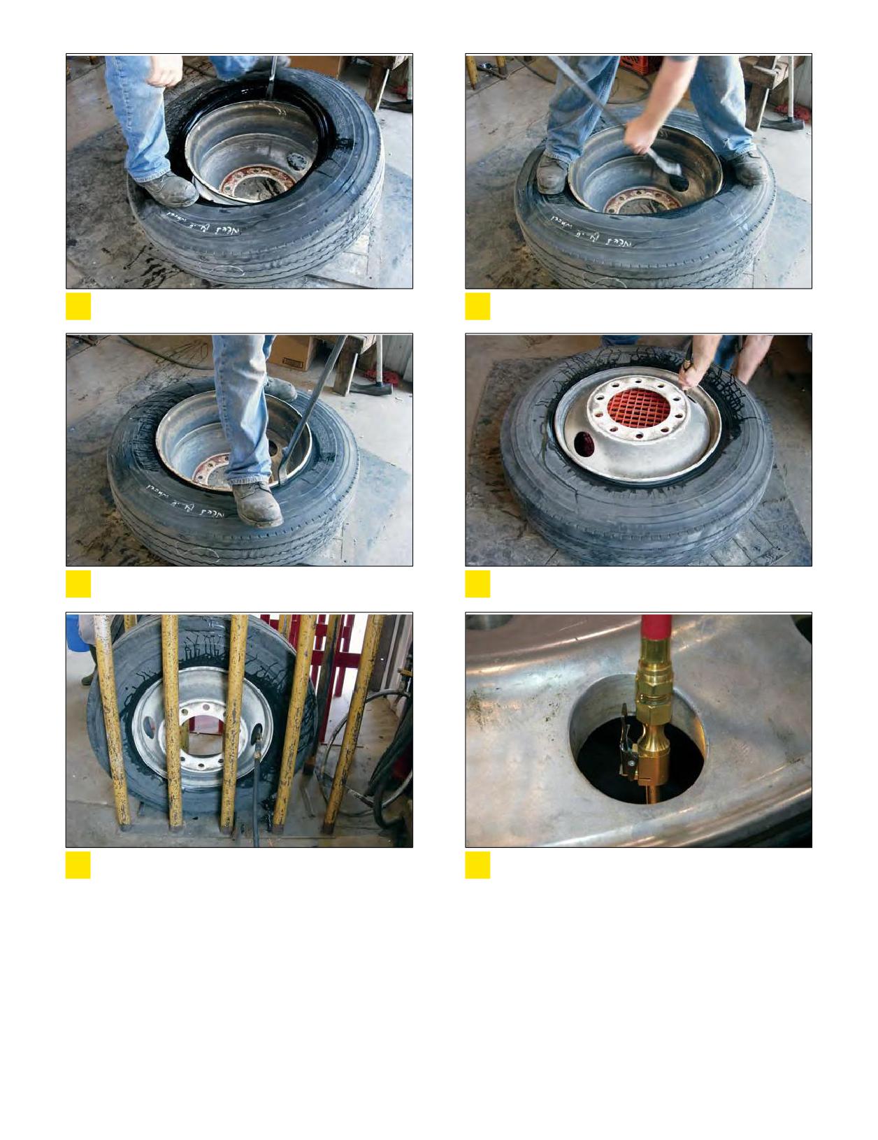
If necessary, continue to work the first bead on with
Mount second bead using same method.
7
8
proper tubeless tire tools like T45A tire iron.
Use the proper tool like T45A tire iron, not the
With assembly horizontal, inflate to no more
9
10
duck bill hammer.
than 5 psi to seat the beads.
Place the assembly in the safety cage for safe
Use a clip-on chuck and allows for a sufficient
11
12
inflation.
length of the hose to extends outside the
safety cage.
TUBELESS TIRE MOUNTING/DEMOUNTING USING A MOUNTING MACHINE
There are several tire changing machines available for the mount and demount procedure. Consult the manufacturer’s user
manual for the machine you are using as each operates differently. Full lubrication of the wheel and BOTH tire beads is still
required. Inflation process requirements remain the same.
Section Three: Mounting the Tire
33
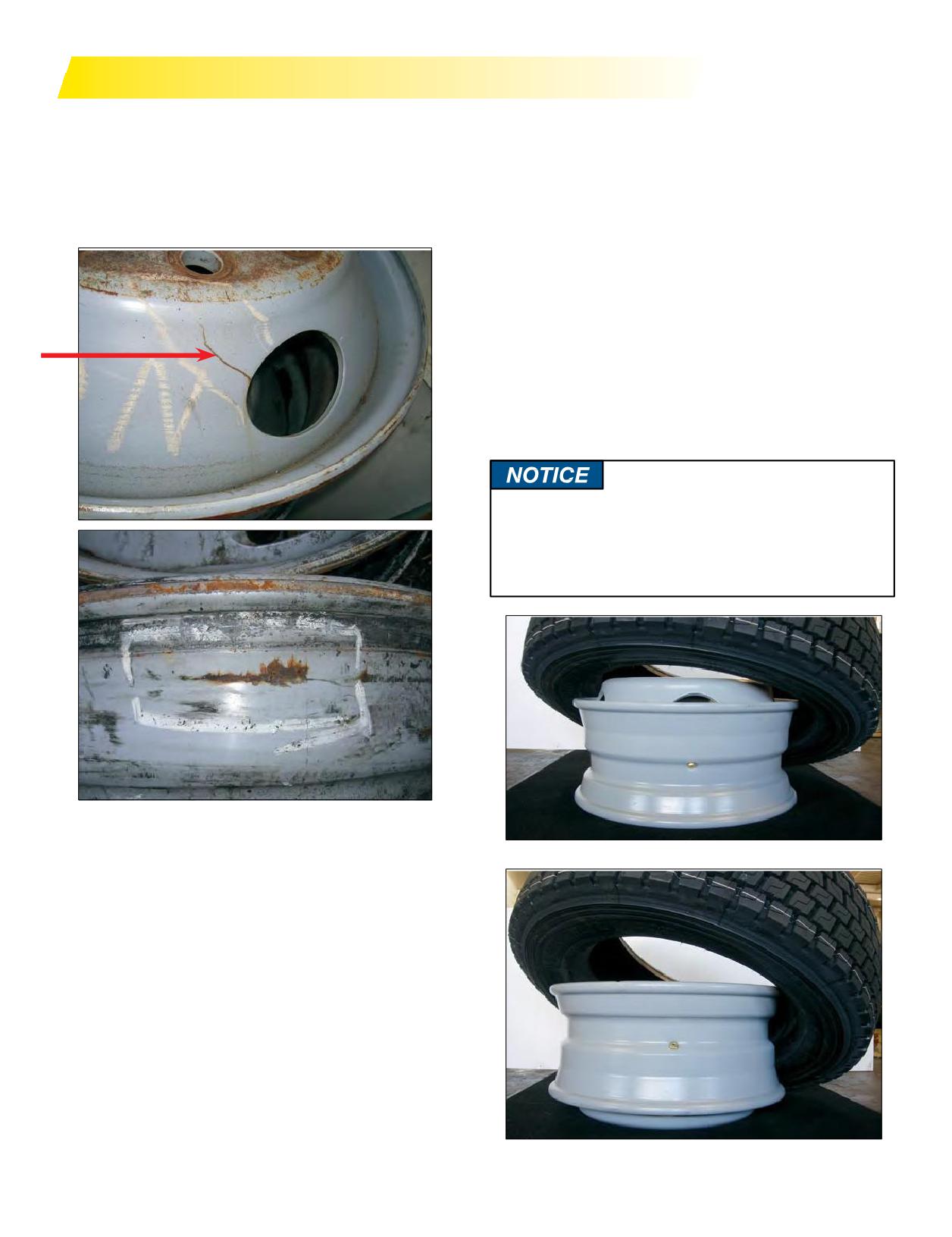
TUBELESS TIRES MOUNTING/DEMOUNTING
MOUNTING TUBELESS
4. With short ledge up, lay the tire over the wheel opposite
1. Inspect the condition of the bolt holes on the wheels, and
the valve side and work it on with proper tubeless tire
look for signs of fatigue. Check flanges for excessive wear
tools,making full use of the drop center well. Drop center
by using the wheel manufacturer’s flange wear indicator.
wheels are typically designed with an off-set drop center
NEVERWELDACRACKEDWHEEL!
to accommodate wheel width and brake clearance. This
creates a “short side” and a “long side” on the wheel.
(Some drop center wheels are designed with a symmetric
wheel profile facilitating tire mounting from either
side.) It is imperative that the tire always be mounted
and dismounted only from the short side. Failure to do
this will likely result in damaged tire beads that could
eventually cause rapid gas loss due to casing rupture.
This is particularly important on 19.5 inch RW (reduced
well) aluminum wheels which, contrary to the norm, have
their drop center located close to the disc side. Do not
use a 19.5 x 7.50 wheel for the 305/70R19.5 tire size.
All 19.5 inch tubeless wheels should be mounted from
the short side. Care should be taken to ensure that any
internalmonitoring systemmolded in the tire or on the
wheel is not damaged or dislodged during this service.
2. Replace valve core, and inspect valve stem for damage
and wear. Michelin recommends always replacing the
Incorrect
valve stem and using a new valve stem grommet. Ensure
valve stem is installed using the proper torque value.
80-125 in/lbs (7-11 ft/lbs) for standard aluminum wheels
and 35-55 in/lbs (3-5 ft/lbs) for standard tubeless steel
wheels. Ensure the valve core is installed using the
proper torque value of 1.5 - 4 in/lbs. To prevent galvanic
corrosion on aluminum wheels, lubricate the threads and
O-ring of the valve stem with a non-waterbased lubricant
before installation.
3. Apply the tire and wheellubricant to all surfaces of the
wheel and bead area of the tire. When applying lubricant
to the wheel, lubricate the entire rim surface of the wheel
from flange to flange. The tire should be mounted and
inflated before the lubricant dries.
Correct
34 Section Three: Mounting the Tire
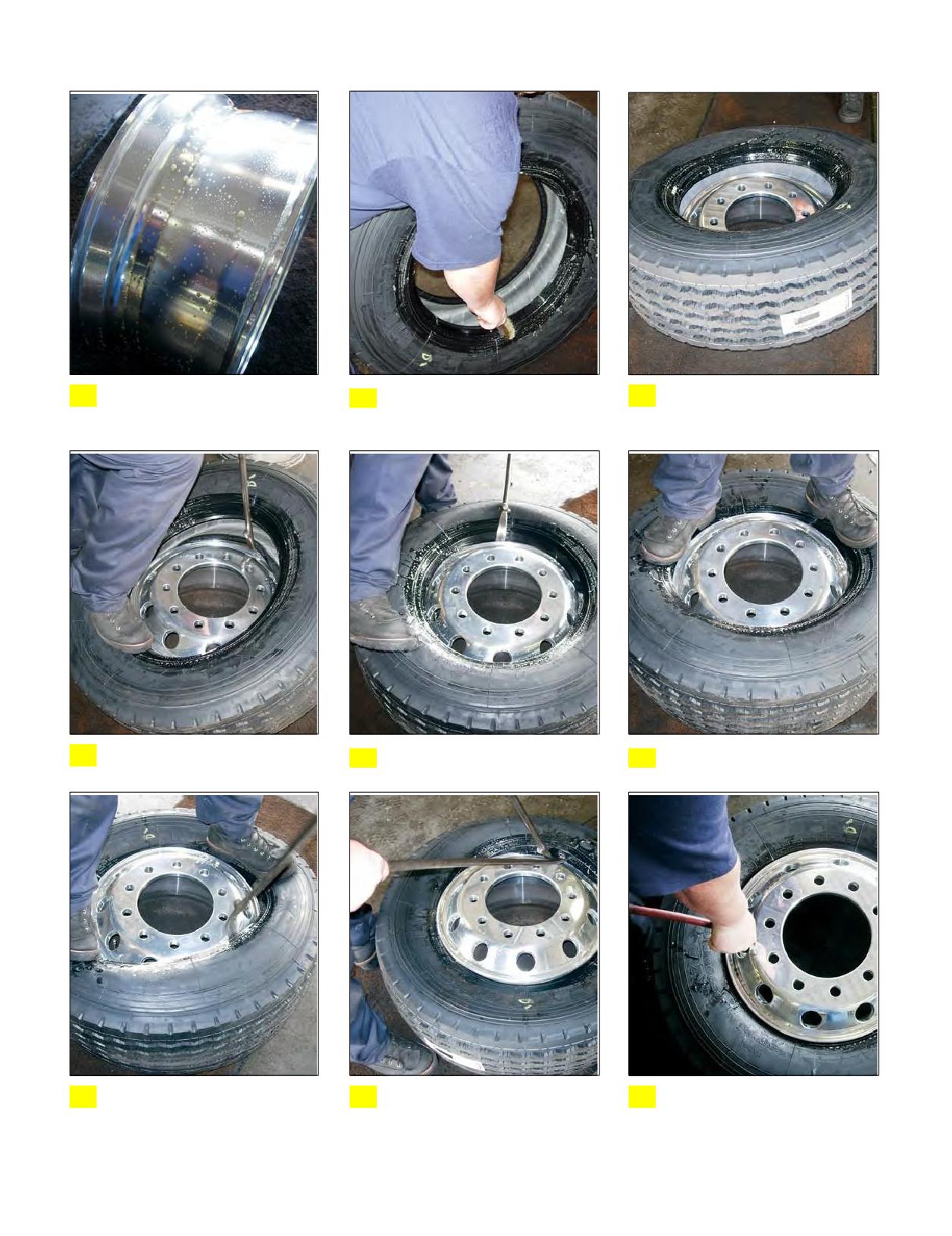
19.5” Aluminum Wheels
Fully lubricate both flanges and
Fully lubricate both beads and
Start with short (narrow) side
1 the drop center.
2
3
the inside of the bead that will
up, disc face up.
be the last one mounted.
Work tire on with proper tube-
Do not use a duck bill hammer
Use rocking motion and
4 less tire tools.
5 here!
6
pressure to place the bead.
Using the proper tool, seat the
Or, seat the bead with the use
Lay the assembly flat, inflate to
7
bead with one tool. Do not use
8
of two tools. Do not use a duck
9
no more than 5 psi, and follow-
a duck bill hammer here!
bill hammer here!
ing proper procedures, complete
inflation process using Safety
Cage (per OSHA standards).
Section Three: Mounting the Tire
35
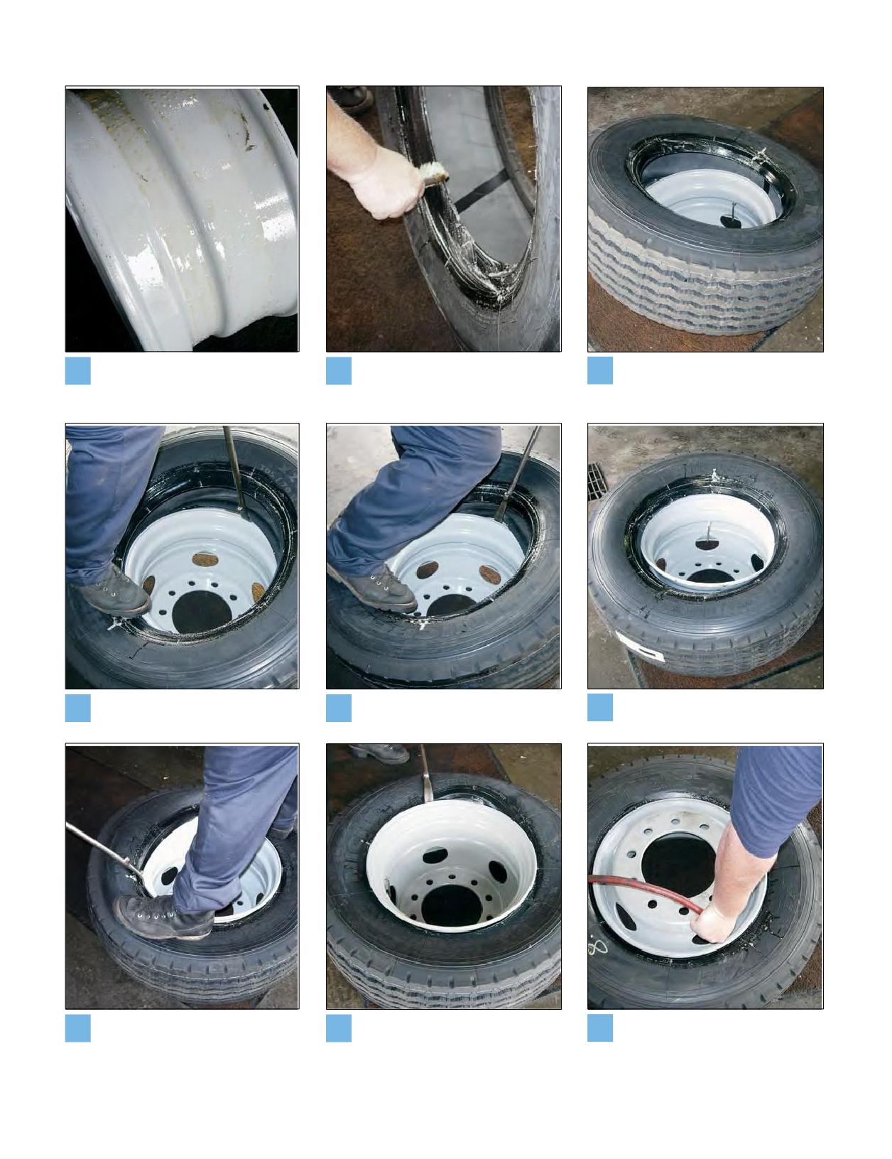
19.5” Steel Wheels
Fully lubricate both flanges and
Fully lubricate both beads and
Start with short (narrow) side
1
the drop center.
2
the inside of the bead that will
3
up, disc face down.
be the last one mounted.
Work tire on with proper tube-
Do not use a duck bill hammer
Place part of second bead in
4
less tire tools.
5
here!
6
drop center.
Using the proper tool, seat the
Use the proper tool to obtain
Turn over assembly, laying
7
second bead.
8
the correct bite. Do not use a
9
horizontal, inflate to no more
duck bill hammer here!
than 5 psi, and following proper
procedures, complete inflation
process using Safety Cage
(per OSHA standards).
36 Section Three: Mounting the Tire
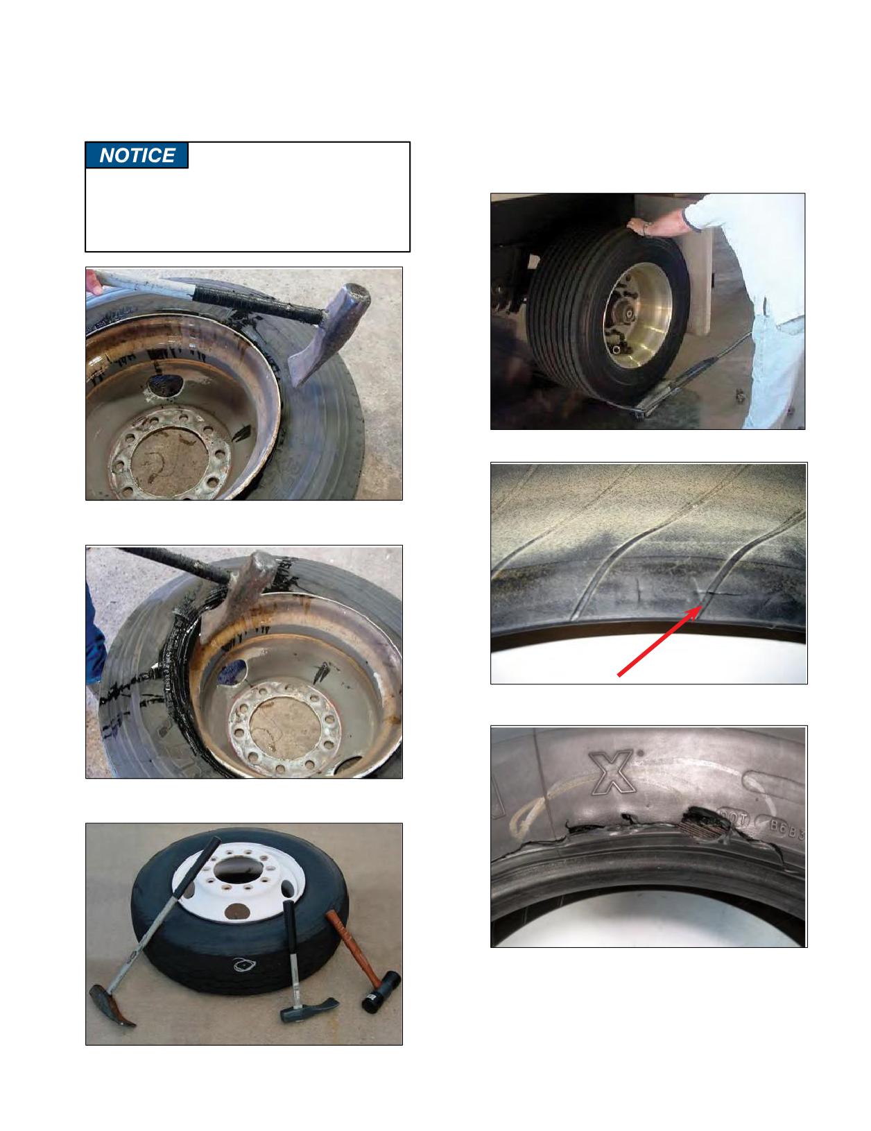
5. Do not use any kind of hammer.
6. The MICHELIN® X One® tire is designed to replace
Severe inner liner damage may occur resulting in
dualtires on the drive and trailer positions of tandem
sidewall separation and tire destruction. Use only
over the road vehicles, and the tires must be mounted
proper mounting levers.
on 22.5 x 14.00” size wheels. Position the tire and
wheel assembly so the valve stem is facing outward,
away from the vehicle.
Do Not use a Duck Billed Hammer during the
mounting process to strike the tire. For proper
use of the duck billed hammer see Page 41.
Do not use a duck bill hammer to break the bead at
demount.
Severe inner liner damage from use of hammer.
Do not use a duck bill hammer to seat either bead
at mounting.
Resulting in sidewall separation and tire
destruction from air infiltration.
Only use a duck bill hammer as a wedge with a
rubber mallet.
Section Three: Mounting the Tire
37
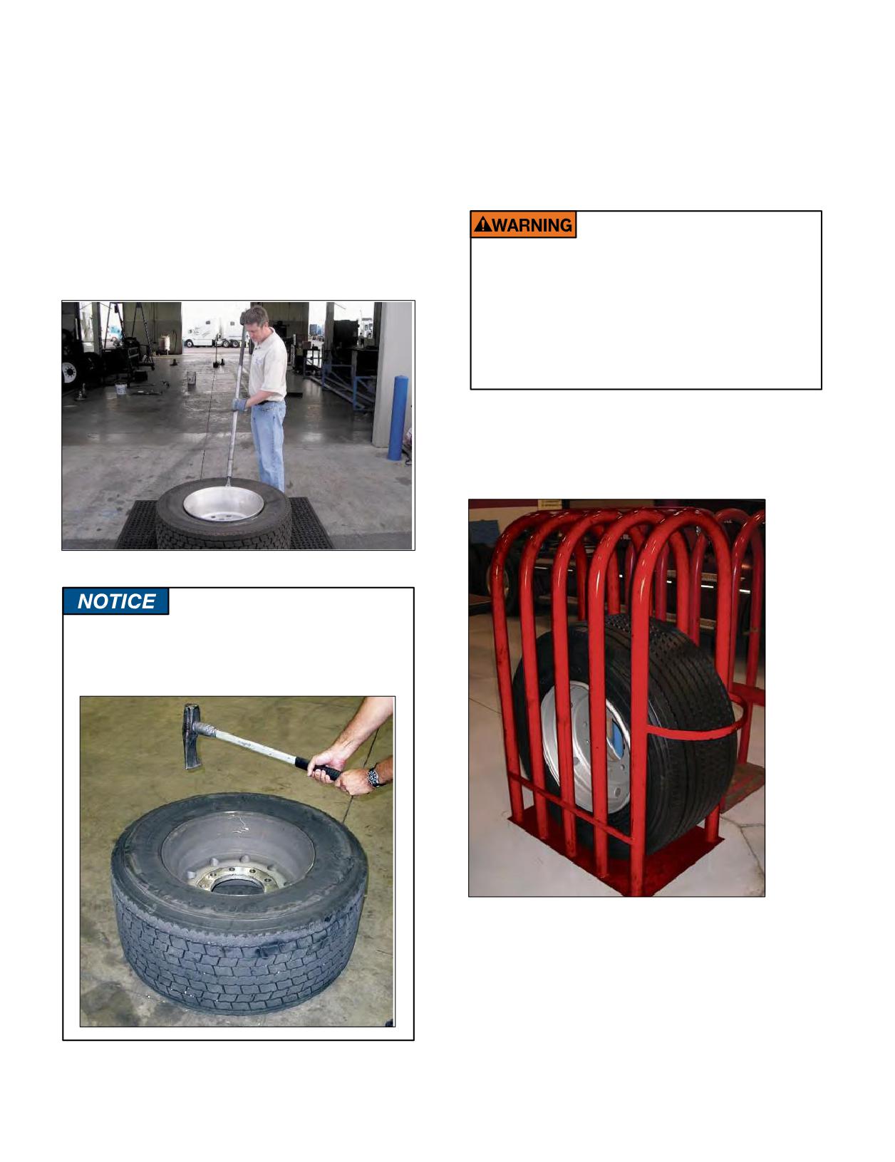
SPECIAL TOOLS / MOUNTING MICHELIN®
X ONE® TIRES
Special tools are available to aid in the mounting and
An extra wide safety cage is available for safe
demounting of the MICHELIN® X One® tire on/off the
inflation of the tire. In most cases, a standard cage can
wheel and the MICHELIN® X One® assembly on/off the
accommodate the MICHELIN® X One® assembly.
vehicle. Due to the size of the tire and wheel these tools
DOT (Department of Transportation) requires that all
will assist the tire technician in providing both safe and
truck tires are to be inflated in an inflation cage.
easy methods of removal and installation.
Whenremoving any tire fromawheel you should use
an Impact Bead Breaker (Slide Hammer) to prevent bead
Tire changing can be dangerous and should be done
damage.Thisis also a safer way to dislodge the tire beads
only by trained personnel using proper tools and
from the wheel.
equipment as directed by Federal OSHA Standard
No. 29 CFR Part 1910.177. Tires may explode during
inflation causing injury to operator or bystander.
Wear safety goggles. Keep all parts of body outside
cage. Use extension hose, clip-on chuck, and remote
valve.
Consult the MICHELIN® Truck Tire Data Book
(MWL40732) or www.michelintruck.com for proper
inflation.
Impact Bead Breaker (Slide Hammer)
Do not use hammers of any type. Striking a
wheel assembly with a hammer can damage
both the tire and the wheel and is a direct
OSHA* violation.
Safety Cage with MICHELIN® X One® Tire
* Occupational Safety and Health Administration
38 Section Three: Mounting the Tire
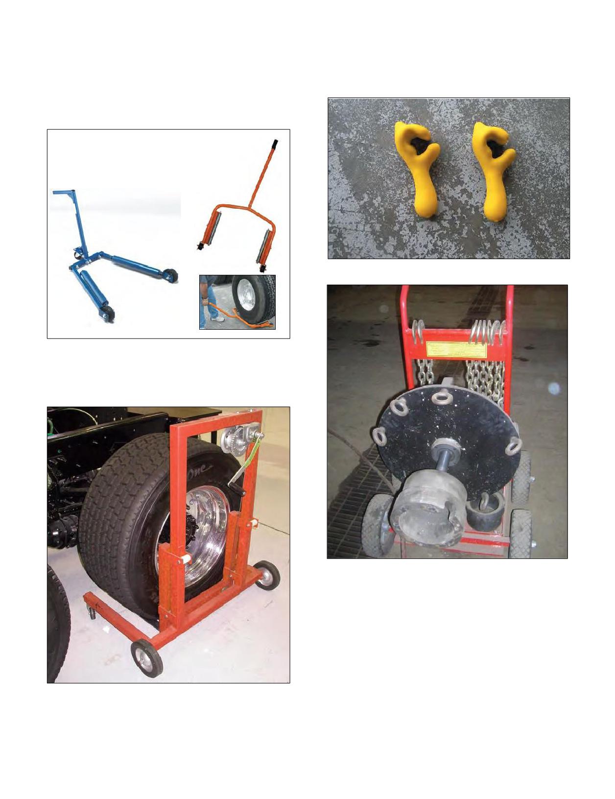
Tools for Handling the MICHELIN® X One® Tire
Some people have difficulty standing on the tire using
Assembly:
conventional mounting techniques, and good devices
Tire and wheel dollies are available from commercial
to help “hold” the bead in place without damaging the
tire supply companies to make the mounting and
wheel are coated bead keepers, shown here.
removing of the assemblies on/off of the vehicle easier.
There are various types to choose.
Bead Keepers
Atire dollymay provide thelifting assistance tomount
or remove the MICHELIN® XOne® tire assembly, which
may help to avoid possible injury.
Special Cart for Removing Stuck Wheels
Tire Dolly
Section Three: Mounting the Tire
39
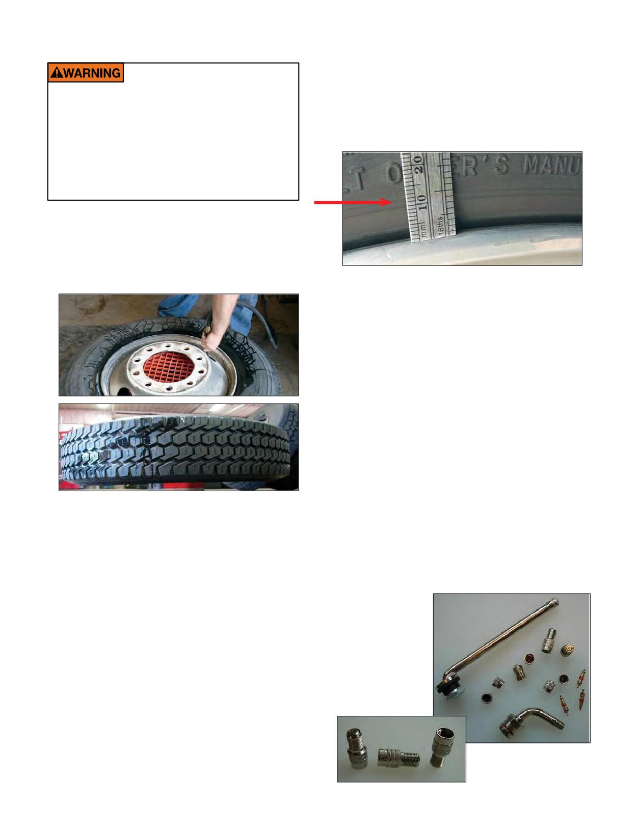
INFLATION OF TUBELESS TIRES
4. Ensure that the guide rib (GG Ring/mold line)
is positioned concentrically to the rim flange
with no greater than 2/32” of difference found
circumferentially. Check for this variation by
Re-inflation of any type of tire and wheel
measuring at four sidewall locations (12, 3, 6,
assembly that has been operated in a run-flat
9 o’clock). If bead(s) did not seat, deflate tire,
or underinflated condition (less than 80% of
normal recommended operating pressure) can
re-lubricate the bead seats and re-inflate.
result in serious injury or death. The tire may
be damaged on the inside and can explode
during inflation. The wheel parts may be worn,
damaged, or dislodged and can explosively
separate.
1.
Lay tire and wheel assembly horizontally and inflate
to no more than 5 psi to position the beads on the
flanges. OSHA dictates no more than 5 psi outside the
cage to seat the beads.
Note: As a general guide in vibration analysis, the
30/60/90 rule may apply:
.030-.060 (1/32 to 2/32 inch) = No action is required.
Limited possibility for vibration exists, and this range
maximizes the ability to balance properly.
.061-.090 (2/32 to 3/32 inch) = Corrective action
would be to perform the 3 R’s, after deflating the tire.
- Rotate the tire on the wheel
- Re-lubricate the tire and wheel (ensure the wheel is
very clean)
- Re-inflate ensuring your initial inflation is with the
tire lying horizontal (3-5 psi max)
>.090 (>3/32 inch) = Perform 3 R’s if mismount is
indicated; however, when the reading is this high, it
usually requires checking runout on these component
parts: wheels/hubs/drums/wheel bearings.
2.
To complete the seating of the beads, place the
5. After beads are properly seated, place the tire in the
assembly in an OSHA (Occupational Safety and
safety cage and inflate assembly to maximum pressure
Health Administration) compliant inflation restraining
rating shown on the sidewall, then reduce to operating
device(i.e. safety cage) andinflate to 20 psi. Check
pressure. Check the valve core for leakage, then install
suitable valve cap. Consider the use of inflate-thru
the assembly carefully for any signs of distortion or
or double seal valve caps for easier pressure
irregularities from run-flat. If run-flat is detected, scrap
the tire.
maintenance.
3.
Ifno damage is detected, continue to inflate to the
maximum pressure marked on the sidewall. USTMA
(U.S. Tire Manufacturers Association) recommends
that any tire suspected of having been underinflated
and/or overloaded must remain in the safety cage
at 20 psi over the maximum pressure marked on
the sidewall. Do not exceed the maximum inflation
pressure for the wheel. USTMA requires that all steel
sidewall tires are inflated without a valve core.
Valve Caps, Cores,
and Stems
Inflate-Thru Valve Caps
40
Section Three: Mounting the Tire
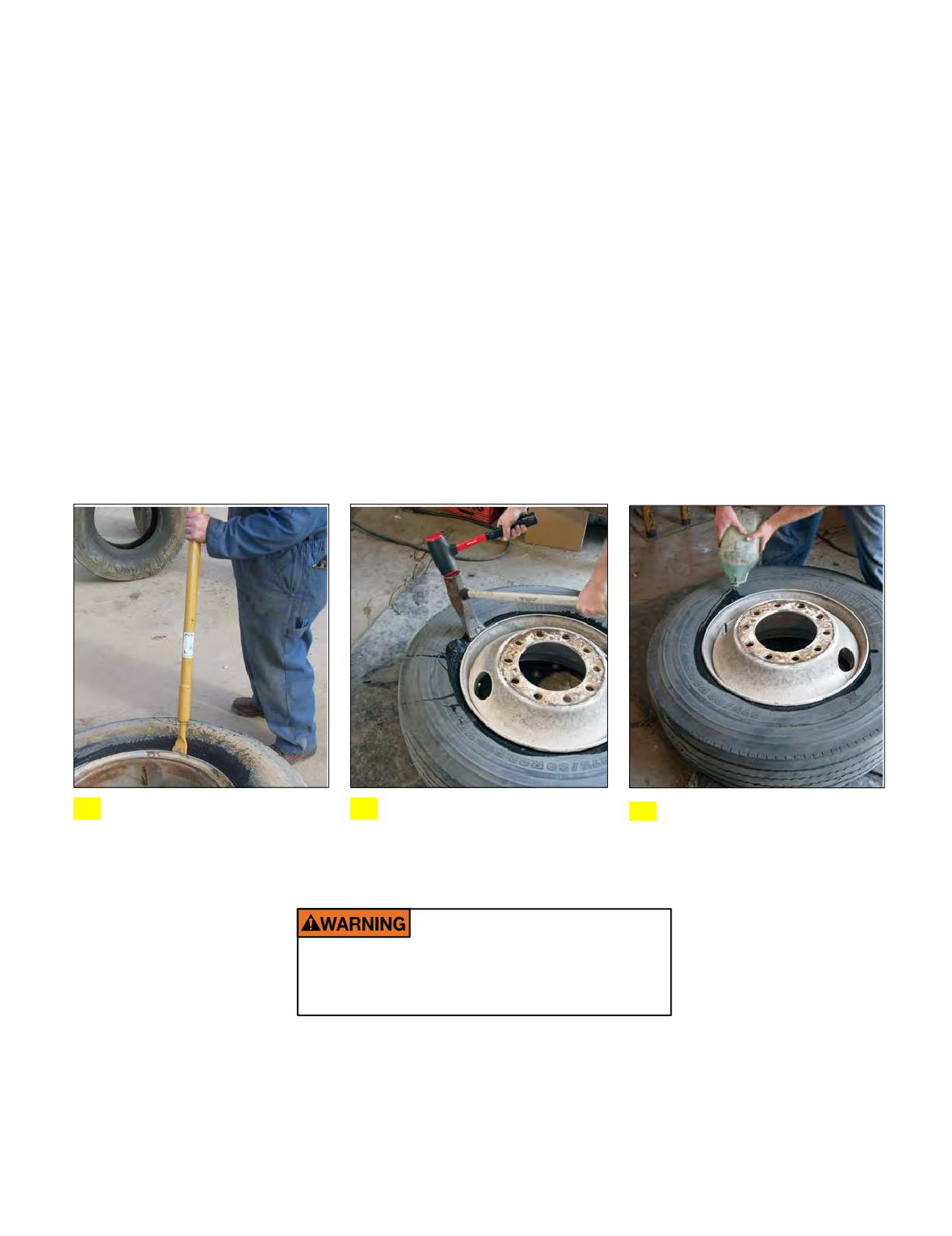
DEMOUNTING OF TUBELESS TIRES
4. Beginning at the valve, remove the tire from the wheel.
1. If still fitted on the vehicle, completely deflate the
Starting at the valve will minimize chances of damaging
tire by removing the valve core. In the case of a
the valve assembly. Make certain that the rim flange
dual assembly, completely deflate both tires before
with the tapered ledge that is closest to the drop center
removing them from the vehicle (OSHA requirement).
is facing up. Insert the curved ends of the tire irons
Run a wire or a pipe cleaner through the valve stem to
between the tire and rim flange. Step forward into the
drop center and drop the bars down, lifting the tire
ensure complete deflation.
bead over the rim flange. Hold one tire iron in position
2. With the tire assembly lying flat (after deflating the
with your foot. Pull the second tire iron out and
reposition it about 90 degrees from the first iron. Pull
tire),break the bead seat of both beads with a bead
the second tire iron towards the center of the wheel.
breaking tool. Do not use hammers of any type to seat
the bead. Striking a wheel assembly with a hammer of
Continue to work tools around wheel until first bead is
off the wheel.
any type candamage the tire or wheel and endanger
the installer. Use a steel duck bill hammer only as
5. Lift the assembly, place and rotate the tire iron to lock
a wedge. Do not strike the head of a hammer with
on the back rim flange, allow the tire to drop, and with
another hard faced hammer - use a rubber mallet.
a rocking motion remove the tire from the wheel.
3. Apply the vegetable-based lubricant to all surfaces of
the bead area of the tire.
Use a Slide Hammer.
Or a duck bill hammer as a
Lubricate both beads completely
1
2 wedge, with a rubber mallet.
3 to avoid demount damage.
Never inflate or re-inflate any tires that have
been run underinflated or flat without careful
inspection for damage, inside and out.
Section Three: Mounting the Tire
41
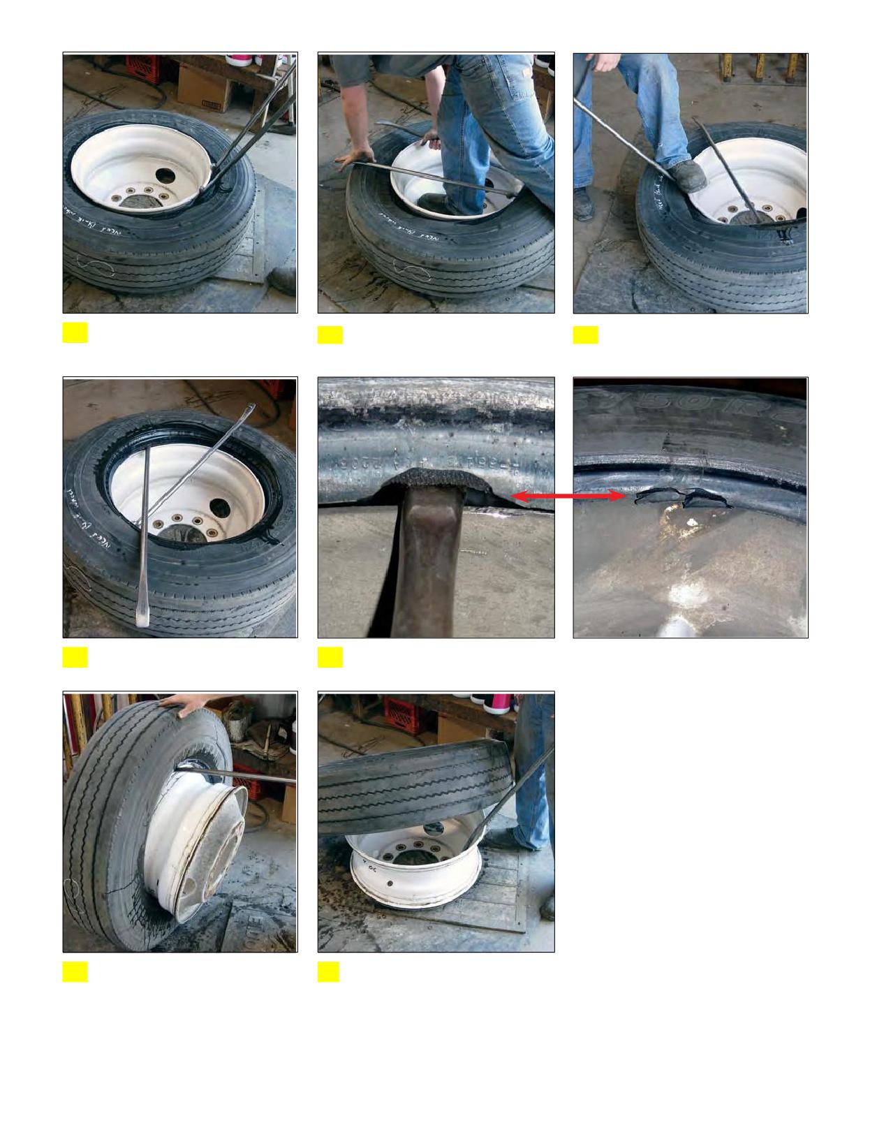
Be sure to start at the valve stem,
Step forward into the drop
Progressively work tools around
4 not away from or opposite.
5 center, laying the bars down.
6 the wheel until the first bead is
off the wheel.
Completely unseat the first bead.
Failure to work with small sections on a non-lubricated bead will result in
7
8
unnecessary damage to the bead.
Lift the assembly, place the tire
Allow the assembly to drop, and
9
iron inside, rotate to lock the
10
rock the tire from the wheel.
tab against the flange.
42 Section Three: Mounting the Tire
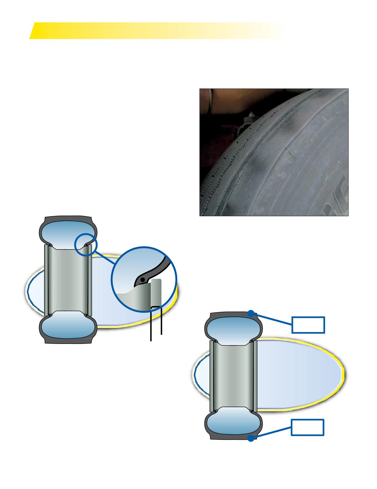
MISMOUNT
Mismount occurs when the tire beads do not seat
If the tiremismount is not detectedimmediately, the
fully on the tapered rim flange area of the wheel. As can
tire may develop localized shoulder wear. Eventually
be seen in this diagram, one of the tire beads has fully
the tire wear pattern will appear around the rest of
seated against the rim flange. But in another small area
the shoulder, sometimes resulting in a noticeable ride
the bead did not “climb” completely up the tapered area
disturbance.
of the wheel. In this area the beadis tucked further under
the wheel making the sidewall slightly shorter. If the
tire continues to run,it will develop “maxi-mini” wear,
which is characterized by the tread depth on one side of
the tire being deeper than on the other side. In this case,
balancing will only be a “band-aid.” In other words, the
tiremay be balanced for a few thousandmiles, but as the
tire wears, the weights would have to magically shift to
another part of the tire and wheel assembly in order to
maintain proper balance. Because they don’t magically
shift to other locations, the driver usually comes back
after a few thousand miles saying “whatever you did, it
worked for a little while, but now the vibration has come
back.”
If mismount is detected early: deflate, dismount,
inspect, re-lube, and re-mount the tire. Sometimes the
Mismount
irregular wear from mismount may be too significant to
fix.At this point you can either send the tire to the trailer
position or retread the casing.
For a detailed discussion on mismount, please refer
to the Runout & Match Mounting video from your
Michelin Representative or visit www.michelintruck.com/
reference-materials/videos/#/maintenance-and-training.
11⁄32”
Maxi-Mini Wear
14⁄32”
Section Three: Mounting the Tire
43
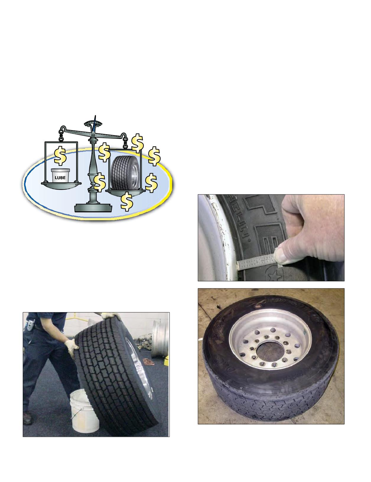
THERE ARE 3 EASY STEPS TO HELP
horizontal is that if the initial inflation is done with the
tire and wheel standing vertically, the weight of the wheel
MINIMIZE MISMOUNTED TIRES:
pushing down on the two beads must be overcome in
1. Use a generous amount of tire lube.
order to center the wheel on the tire. A MICHELIN®
X One® tire wheel weighs between 70 and 125 lbs. and
it can be very hard to overcome gravity if tire beads are
Makesure that you only dilute the lube to the
seated with the tire and wheel inflated standing up.
specifications of the manufacturer. Some shops will try to
Occupational Safety and Health Administration (OSHA)
dilute the lube additionally to savemoney. This is a bad idea
guidelines require the tire to be inflated in an approved
because the dollar or two you save on a bucket of lube won’t
be worth replacing a tire due to irregular wear caused from
safety cage. However, the first 3 to 5 psi of pressure may
be applied to the tire outside the safety cage to properly
mismount or damaged beads.
seat the beads.
3. Inspect the guide rib to ensure that the tire is
concentrically mounted.
Using a small machinist’s ruler (available at most
hardware stores for ~$2), check the wheel flange to the
guide rib on your inflated tire. The maximum variation
allowed is 2/32”. You should check the wheel flange to the
guide rib at 4 locations: 12:00, 3:00, 6:00, and 9:00.
2. Inflate the assembly enough to seat the beads
with the tire laying horizontally or parallel to
the ground.
A good practice to follow that will ensure the tire beads
are seated properly is tolay the tire and wheel horizontally
ontheground,or better yet, use a 5 gallon bucket as a stand,
whichwill keep the bottomsidewall from touching the
12
ground.Thereasonyouwanttoseat thebeadswiththe tire
9
3
6
Five gallon bucket filled with weights.
44 Section Three: Mounting the Tire
MOUNTING THE ASSEMBLY ON THE VEHICLE
When wheel assemblies are mounted on a vehicle, be
DUAL SPACING
sure that the valves do not touch the brake drums or any
It is also important that sufficient space is provided
mechanical part of the vehicle. When mounting the
between dual tires to allow air to flow and cool the tires and
MICHELIN® X One® tire utilizing a 2” outset wheel onto
to prevent the tires from rubbing against one another.
a vehicle, position the tire so that the tire sits on the
To make sure dual spacing is correct, simply measure
outboard side of the wheel similar to where the outer dual
from the outside edge of the outer tire to the outside edge
would normally be positioned. Position the tire and wheel
of the inner tire of the dual assembly. This will give you
assembly so the valve stem is facing outward, away from the
the center to center distance of the duals across that axle
vehicle.
end. Refer to theminimumdualspacing columninthe
Valves of dual tires should be diametrically opposite.
application data books.
Ensure that the inside valve is accessible so the pressure can
be checked and maintained.
TECHNICAL CONSIDERATION FOR
Tires mounted in dual
FITTING TIRES
must be matched so that
When fitting tires of sizes different than those specified
the maximum difference
by the vehicle manufacturer, the following points must be
between the diameters of
considered:
the tires does not exceed
1. GEAR RATIO
1/4” diameter or a
A change in tire dimension will result in a change in
circumferential difference
engine RPMata setcruisespeed, whichwill resultin
of 3/4”.For tires of the same
Incorrect Dual Wheel
Placement
a change in speed, tractive effort, and fuel economy.
bead diameter and size, the
Therefore, the effect of a tire size change on the gear ratio
maximum allowable difference in tread depth is 4/32”.
should be considered in individual operations. Generally,
Failure to properly match dual tires will result in the tire
changes of 2% for a given diameter or less will have a
with the larger diameter carrying a disproportionate share
negligible effect on gear ratio, tractive effort, and indicated/
of the load.Mismatched duals canlead to rapid wear,
actual speed. If a smaller wheel diameter is chosen, make
uneven wear, and possible casing failure.
sure that brake over wheel clearances are checked before
Tandem drive axle vehicles without an inter-axle
continuing with the mounting. (Changes in diameter of
differential (or when it is locked out) necessitate that
more than 3% percent should be discussed with the vehicle
tires are closely matched. The inter-axle differential is a
manufacturer.)
gear device dividing power equally between axles and
• The formula for calculating the top speed is:
compensating for such things as unequal tire diameters, the
Top Speed (MPH) = Engine RPM x 60
effect of front and rear suspensions, torque rod positioning
(Tire Revs./Mile) x R
and the like on the working angles of the universal joints.
Where MPH = Miles Per Hour
Normally in the unlock position, this provides minimized
RPM = Revolution Per Minute (Engine)
wear and tear on tires and the drivetrain. Tandem drive
R = Overall Gear Reduction
rear axles (twin-screw) require that the average tire
• Since engine RPM and R will remain the same when
circumference on oneaxle bewithin 1/4” of the average tire
changing from one tire to another, the comparison is
diameter on the other axle to prevent damage to the drive
simply a straight ratio of the Tire’s Revs./Mile.
differentials resulting from different revolutions per mile on
Example: Tire Revs./Mile
the drive axles.
11R24.5 MICHELIN® XDN2®
=
473
Since any one tire of the size used with these axlesmay
455/55R22.5 MICHELIN® XDN2® =
495
lose as much as 2.5” in circumference due to normal
Ratio
473/495
=
0.96
wearandstill be serviceable,itis readily seen that a wide
(= 4%. This change requires a gear ratio change
difference in tire circumference may exist.
aswell as a speedometerchange orECM
Equal tire inflation (between adjacent duals) at the
(Engine Control Module) program adjustment.)
pressures recommended by the tire manufacturer should
Therefore, when the vehicle’s speedometer reads 75 mph,
be maintained.
the vehicle is actually traveling 72 mph.
IMPORTANT: Check to ensure that you know which
mounting system you are working with and that the
components are correct. For additional information, see
Wheel Systems on Pages 16-18 of Section Two, Selecting a
Wheel.
Section Three: Mounting the Tire
45
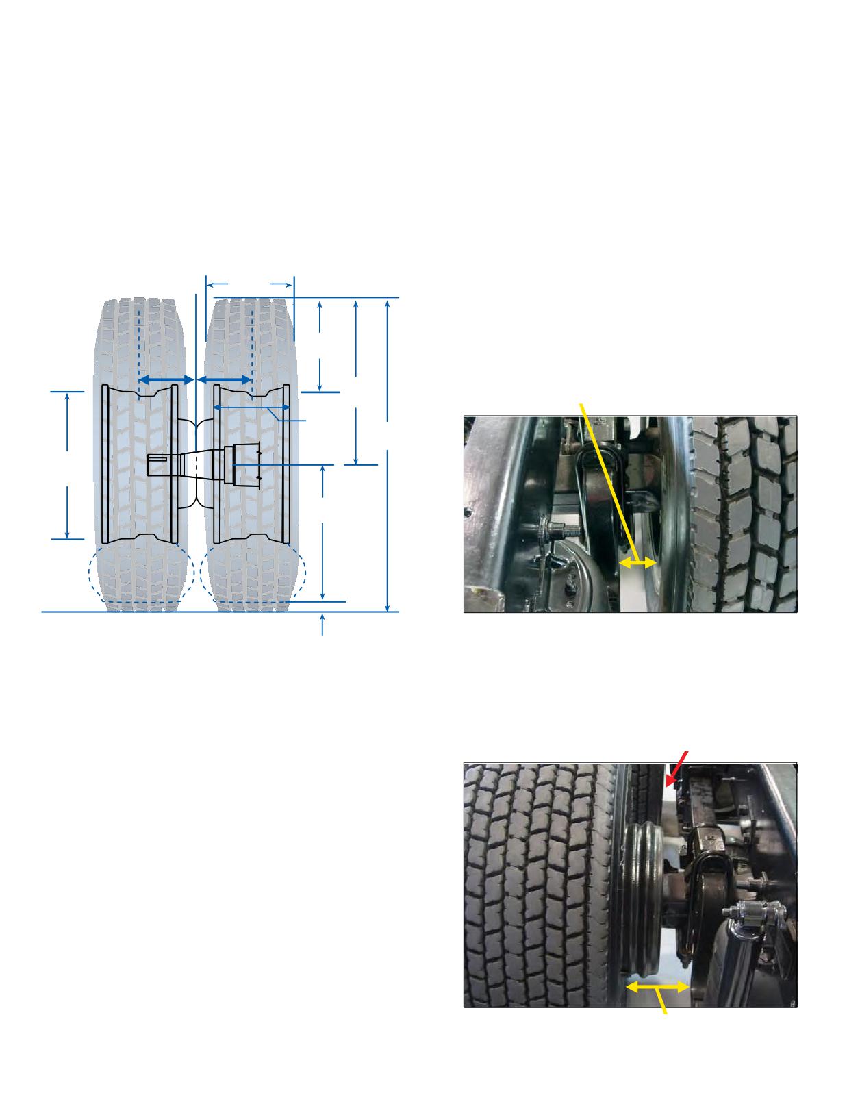
If the governed speed for a vehicle originally equipped
5. TIRE CLEARANCES
with 455/55R22.5 tires is 75 mph, the top speed with
All clearances around a tire should be checked:
11R24.5 will be (495/473) (75 mph) = (1.05) (75 mph) = 78.8
• To the nearest fixed part of the vehicle, i.e., to parts
mph.The speedometerwill read75mph whenthe vehicle
that are not affected by spring deflection or steering
is actually traveling 78.8 mph.
mechanism.
Rule of Thumb: When going from a lower Tire Revs./Mile
• To the nearest part of the vehicle, which can be moved,
to a higher Tire Revs./Mile, the actual vehicle speed is less
i.e. parts that are affected by spring deflection or
than the speedometer reading. When going from a higher
steering mechanism.
Tire Revs./Mile to a lower Tire Revs./Mile, the actual vehicle
Consideration should be given to any additional clearance
speed is greater than the speedometer reading.
required by the use of chains. Minimum clearances
recommendation: 1”.
2. WHEEL DIAMETER
Overall
a. Lateral Clearances
Width
Lateral clearance is the smallest distance horizontally
between the tire and the nearest fixed point of the vehicle.
Lateral clearance will be reduced by an increase in the
Section
Height
Wheel
Wheel
offset of the inner wheel plus half of any increase in the tire
Outset
Inset
section.
Free
Radius
Lateral Clearance
Rim
Width
Overall
Diameter
Nominal
Wheel
C
Diameter
Loaded
Radius
Note: When using a 2” outset wheel, the MICHELIN®
Deflection
XOne® tireshouldbemountedsothatthetiresits outward
3. WHEEL WIDTH
similar to an outer dual tire. However, use of outset wheels
Anincrease in the tire section may require a wider rim
may change Gross Axle Weight Rating (GAWR). Consult
with a greater outset.
vehicle manufacturer.
4. WHEEL OUTSET/INSET FOR DUAL WHEELS
Incorrect Lateral Clearance
The minimum wheel outset required is determined
by the tire minimum dual spacing. Outset is the lateral
distance from the wheel centerline to the mounting surface
of the disc. Outset places the wheel centerline outboard
of the mounting (hub face) surface. Inset is the lateral
distance from the wheel centerline to the mounting surface
of the disc. Inset places the wheel centerline inboard of the
mounting (hub face) surface.
OFFSET for front wheels: When retrofitting steer axles
with tires and wheels of a width different from the OE size,
wheel offset must be considered. Wheel offset should be
chosen to avoid interference with vehicle parts and also to
avoid exceeding overall vehicle width regulations.
Correct Lateral Clearance
46 Section Three: Mounting the Tire
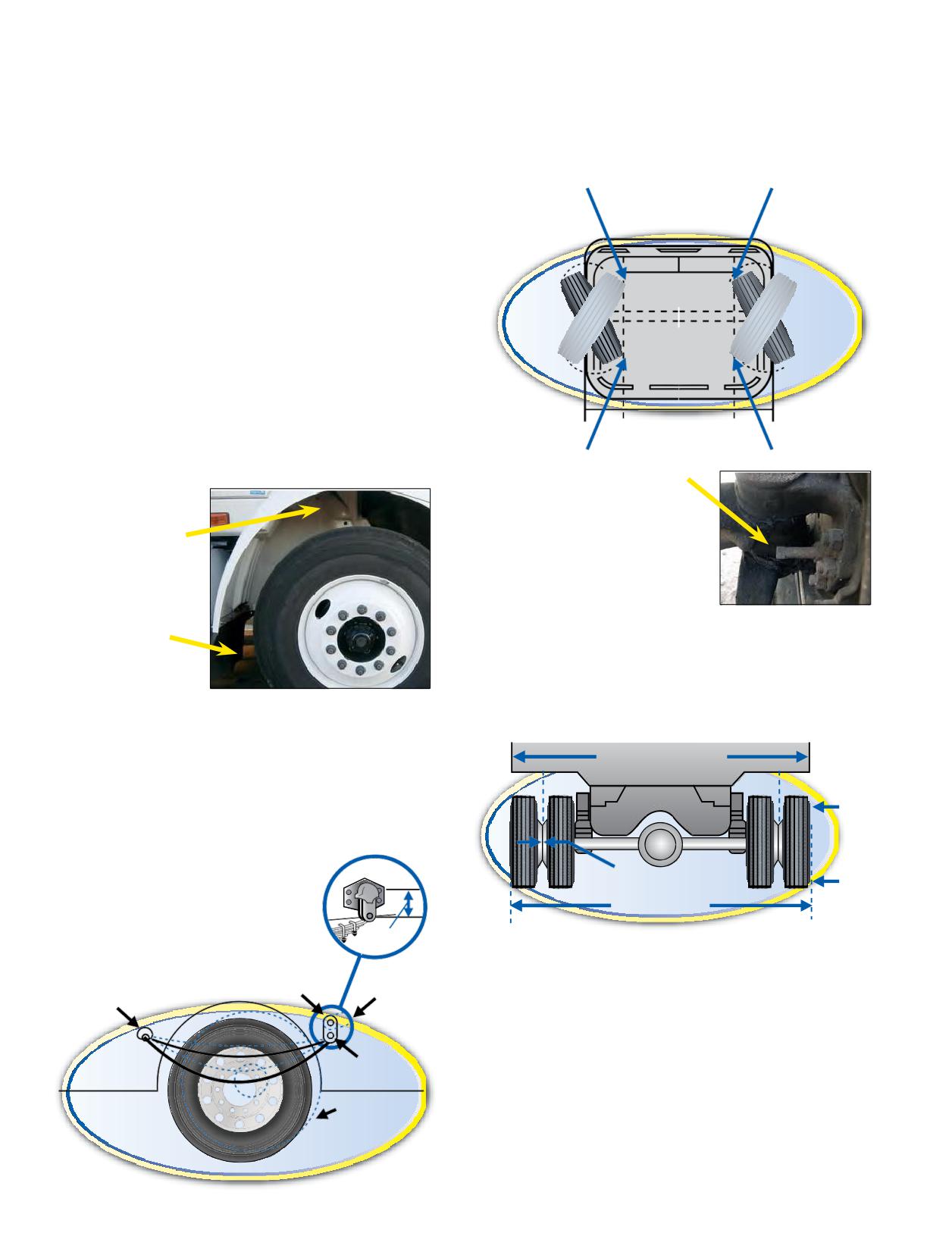
b. Vertical Clearances
d. Front Wheel Clearances
Vertical clearance is measured between the top of the
The clearances of both front wheels must be measured
tread and the vehicle component immediately above the
on both steering lock positions. Clearances of front wheels
tire (usually a fender). This will vary as the springs operate.
mustbe checked by turning the wheels from full left lock to
The vertical movements of the whole axle, in relation to
full right lock since the minimum clearance might occur at
the whole chassis, are normally limited by an axle stop.
some intermediate point.
When measuring vertical clearance, subtract the axle
Check Clearances Here
and All Positions
stop clearance from the total clearance; the difference is
From Lock to Lock
the remaining vertical clearance. When checking vertical
clearance, consideration must be given to the degree of
tread wear, and an allowance of 1” must be made if the
tread on the existing tire is between 2/32” and 4/32”.
Vertical and body clearances are decreased by any
increasein the free radius of the tire.
When using tire chains, a minimum of two inches of
clearance is needed to provide space between the dual
assembly and the vehicle.
Check to be sure that the body clearance is not less than
Bottom View
the vertical clearance. A fender boltmay be closer to the
tire than the fender. This, then, is the smallest distance and
should be recorded.
Steering Stops should be
measured as they control the
angle of the turn. Ensure they
Vertical Clearance
exist and are not damaged.
Damage may indicate
clearance issues or be a cause
of abnormal tire wear.
Body Clearance
6. OVERALL WIDTH
When fitting larger tires, the overall width of the vehicle
across the tires is increased by half of the increase in the
cross section of each outside tire and the increase in offset
c. Longitudinal Clearances
of each outside wheel.
The semi-elliptical spring method of suspension permits
Overall Width of Body
the axle to move back longitudinally as well as vertically
when the spring deflects. As a guide, the maximum
backwardmovementmaybetakenasonethirdofthe
Measure
distance between the shackle pin centers. The remaining
Here
longitudinal clearance must be noted.
0” Outset
Not Here
Overall Width
75 mm
(3”)
7. SPARE WHEEL RACK
Fixed Pivot
Always check the spare wheel rack to see that the tire
Swing Pivot
Fixed Pivot
will fit. Ensure that location is notin proximity to engine
exhaust.
Spring
8. LEGAL LIMITS
Shackle
Most states and provinces in North America have legal
Longitudinal
limits for vehicle carrying capacities, overall vehicle
Clearance
dimensions, and minimum ground clearances. Each of
these factors must be taken into consideration. Check with
local jurisdictions.
Section Three: Mounting the Tire
47
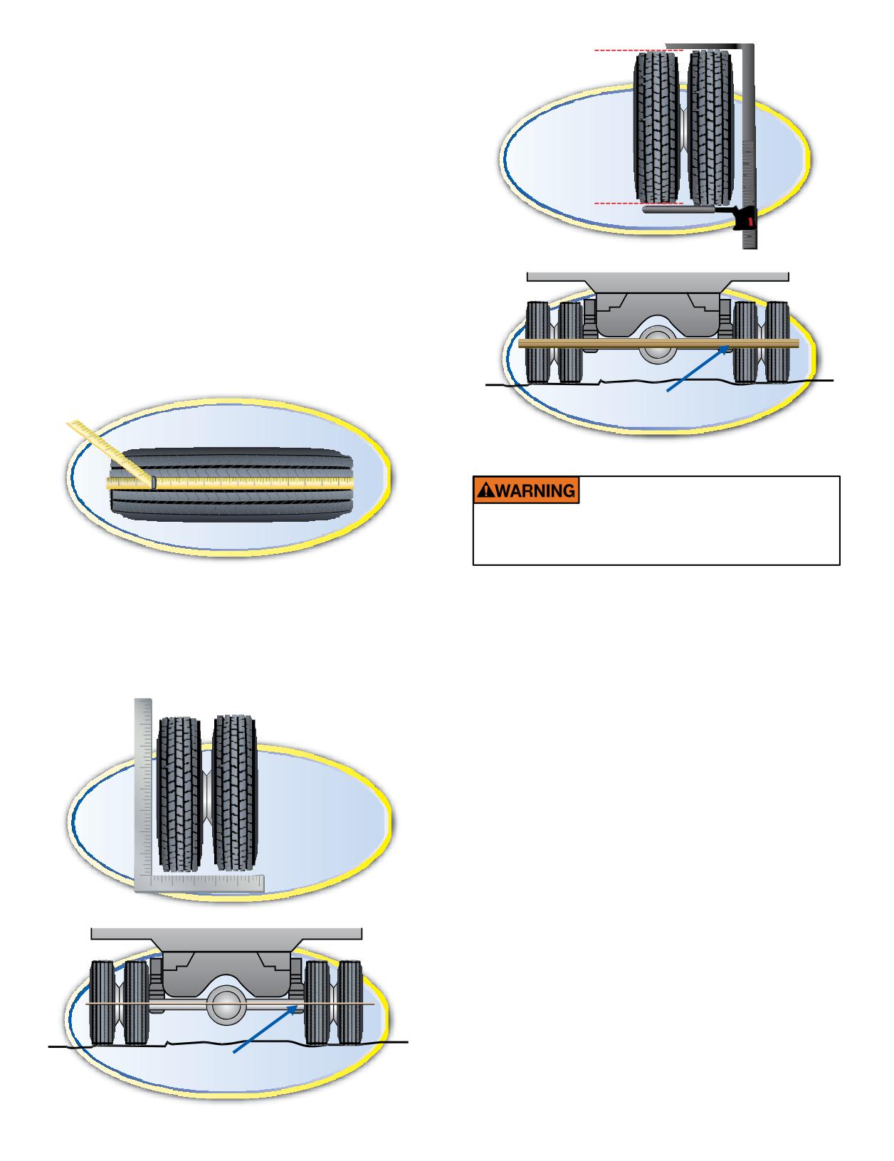
MEASURING TIRES IN DUAL ASSEMBLY
Ifdrive and trailer tires are of equal tread depth and have
equal inflation pressure, the inner tire in the dual assembly
is subjected tomore deflection, as it is under a heavier load
and is affected by the condition of the road on which it
(C)
operates. This result of road slope (Interstate System and
Use of the Calipers
primaryroads) or road crown(secondary roads) on the
inner tire is more grip than the outer tire achieves. Thus, the
inner tire dictates the revolutions per mile of the assembly,
resulting in the outer tire having more rapid tread wear.
Measuring the circumferences of the tires with an endless
tape after they are on the wheels and inflated, but before
they are applied to a vehicle,is themost accuratemethod.
The endless tape, as the name signifies, is a tapemade of one
half inch bending steel, one end of which passes through a
slot at the other end of the tape and forms a loop. Measuring
in this manner takes into account any irregularities in wear.
(D)
Use of a Wooden Straight Edge
Measuring with Endless Tape
TIRE MIXING
Do not drive on improperly mixed tires. Doing so
can lead to tire failure and /or handling issues
leading to an accident, personal injury or death.
In checking tires already on avehicle, the followingmay
Trucks with four wheel positions: For the best
beused:(A) a square (similar to butlarger thana carpenter’s
performance it is recommended that the same size, design,
square), (B) a string gauge, (C) a large pair of calipers, or (D)
andconstructionof tire be used on all four wheel positions.
awoodenstraightedgelongenoughtolie across the treads
If only two MICHELIN® radials are mounted with two non-
of all four tires.
radials, the radials should be mounted on the rear. If tires of
different design are mixed on a vehicle in any configuration,
they should not be used for long periods, and speeds* should
be kept to a minimum
Mixing ormatching of tires on 4-wheel drive vehicles may
require special precautions. Always check vehicle
manufacturer’s Owners Manual for their recommendations.
Trucks with more than four wheel positions: For best
(A)
performance, it is recommended that radial and non-radial
Use of a Square
tires should not bemixedin dual fitment. Itis unlawful and
dangerous to mix radials and bias tires on the same axle.
*Exceeding the safe, legal speed limit is neither recommended nor endorsed.
RUNOUT
The ideal time to verify that proper mounting procedures
have resulted in concentric bead seating is during the
installation of new steering tire/wheel assemblies. The ‘on
vehicle’ assembly radial and lateral runout measurements
should be the lowest possible to offer the driver the
smoothest ride. Both the guide rib variance and the hub to
wheel clearance on hub piloted assemblies can be measured
(B)
following the procedures found in the Runout and Vibration
Use of String Gauge
Diagnosis guidelines on Pages 176-178 of Section Ten,
Appendix.
48 Section Three: Mounting the Tire
SECTION FOUR
Extending Tire Life
- Tandem Axle Parallelism (Skew - Thrust)
Section Four
- Thrust Angle (Tracking)
Extending Tire Life
49-80
- Camber
MAINTAINING THE TIRE
50-58
- Caster
Inflation Pressure
50
- Steer Axle Setback (Steer Axle Skew)
- Underinflation
- Toe-Out-On-Turns (Turning Radius)
- Overinflation
- TMC Recommended Alignment Targets
- Proper Inflation
- Periodic Alignment Checks
- How to Properly Measure Pressure
- Alignment Equipment
- Temperature/Pressure Relationship Graph
- Field Check Techniques
- Nitrogen
- Axle Parallelism and Tracking
Footprint Comparisons to Dual Tire Fitments
- How to Check Axle Parallelism and Tracking
Sealants - Foreign Matter in Tires
Tire Wear Patterns Due to Misalignment
70
Tire Inspection
- Toe Wear
Automated Tire Inflation System (ATIS) or Tire
- Free Rolling Wear
Pressure Monitoring System (TPMS)
- Camber Wear
Drive Carefully
- Cupping Wear
Tread Depth Measurements
- Flat Spotting Wear
Wear Bars
- Diagonal Wear
Do Not Overload
Irregular Tire Wear
73
Drive at Proper Speeds
- Heel-Toe
Balance and Runout
- Center Wear
CARE, CLEANING, AND STORAGE
59-62
- River Wear Only
Storage
- Step-Shoulder/Localized Wear Shoulder Cupping
Stacking of MICHELIN® X One® Tires
- Brake Skid
Flood Damage
Braking Systems and Issues
75
Cleaning and Protection
- Summary of Tire Issues Due to Brakes
Diesel Fuel Contamination
- Brake Heat Overview
Chains
Fifth Wheel Maintenance and Placement
78
Tire Damage Resulting from Non-Compliant
Wheel Bearing and Hub Inspection
78
Runflat/Beadlock Devices
Suspensions
78
Recommendations for Use of Dynamometers
- Air Suspension Systems
Spinning
- Quick Checks for Trailer System Faults
Rotation
- Quick Checks for Front Suspension Faults
Siping
- Quick Checks for Rear Suspension Faults
Branding
MAINTAINING THE VEHICLE
63-80
Major Vehicle Factors That Affect Tire Life
63
- Alignment
- Steer Axle Geometry
- Toe
Section Four: Extending Tire Life
49
MAINTAINING THE TIRE
Pressures on all newly delivered equipment should be
detector type spray such as a water/soap solution applied
verified for the application/operation prior to the vehicle
from a spray bottle. It is also a good practice to periodically
being placed in service. Verify that any pressure monitoring
check existing fitments for slow leaks with this method.
or inflation system is correctly set for your fleet application
Never bleed hot tires, as your tires will then be
on the delivery of any new equipment.
underinflated. Make sure to check both tires in a dual
Proper maintenance is important in order to obtain
fitment. Pressures should be the same. Maximum
maximum performance.
allowable difference between dual tires or between axles
should be no greater than 5 psi.
INFLATION PRESSURE
Remember, a drop in ambient temperature results
The most critical factor in tire maintenance is proper
in a drop in tire pressure. More frequent checks may be
inflation. No tire or tube is completely impervious to loss
required during cold weather conditions. Avoid outdoor
of pressure. To avoid the hazards of underinflation, lost tire
pressure checks when the temperature is below freezing.
pressure must be replaced.
Ice can form in the valve stem, thus promoting leaks.
Driving on any tire that does not have the correct
Check inside a heated facility if possible.
inflation pressure is dangerous and will cause tire damage.
Use an accurate calibrated tire gauge to check pressures.
Any underinflated tire builds up excessive heat that may
(Do not use “Tire Billys” to hit tires as an inflation check.
result in sudden tire destruction. The correct inflation
This is an unreliable method.)
pressures for your tires must incorporate many factors
Unless otherwise recommended by tire manufacturer for
including: load, speed, road surface, and handling.
optimized tire performance, use the tire inflation pressure
Consult a Michelin Truck Tire dealer or MICHELIN®
shown in the application data books for the particular
data books for the proper inflation pressures for your
axle load. Exceeding this pressure could result in reduced
application. See Section Ten, Appendix (Page 186) for
traction and tread life.
complete listings of the MICHELIN® data books.
Never inflate to cold pressure beyond the rated capacity
Failure to maintain correct inflation pressure may
of the wheel. However, for steering tires, it is common
result in sudden tire destruction and/or improper vehicle
practice to use higher inflation pressures than necessary to
handling. Additionally it willresult in irregularwear.
carry the axle load to reduce free rolling wear.
Therefore, inflation pressures should be checked weekly
Following are two examples of applying the previous
and always before long distance trips.
considerations to an operation where the user mounts
Check inflation pressures on all your tires at least once a
new 275/80R22.5 LRG (with a data book maximum of 110
week, including spares, before driving when tires are cold,
psi tires) steer tires and desires to increase the pressure in
especially when vehicle is used by more than one driver.
order to see if this will help alleviate the occurrence of free
The ideal time to check tire pressures is early morning.
rolling wear.
Driving, even for a short distance, causes tires to heat up
Example 1: If the axle load is 10,310 lbs., then the table in
and pressures to increase.
the data book specifies a corresponding pressure of 85
Generally, as a radial tire revolves during operation,
psi. Then the user can increase the pressure 15-20 psi
heat is generated on the inside of the tire at 4 degrees per
above that to 100 or 105 psi.
minute. However, the tire loses heat at the rate of 3 degrees
Example 2: If the axle load is 12,350 lbs., then the table
per minute with dissipation throughout the casing and
in the data book recommends 110 psi. As this is the
air flow around the tire. After 40 minutes of continuous
maximum load of the tire, only a 10% pressure increase
operation, the tire temperature has increased 40 degrees
is permitted. Thus the adjusted pressure would be
Fahrenheit. As the temperature inside the tire increases,
limited to 120 psi.
the inflation pressure also increases. Thus, a tire inflated
This procedure should not be applied “across the
to 80 psi cold would now be at 85 psi. Because the inflation
board.” If satisfactory tire performance and wear are being
pressure has increased, the amount of tire flexing has
obtained with “table” pressures for a given load, then leave
decreased, which decreases the amount of heat generated
well enough alone.
per minute to 3 degrees per minute. Assuming the heat
Overinflation can cause an increase in road shocks and
dissipation factor is still 3 degrees Fahrenheit per minute,
vibrations transmitted to the vehicle as well as an increase
the net temperature change is nil (0). This is called thermal
in tire failures from road hazards.
equilibrium.
NOTE: In no case should the maximum capacity of
Always inspect valve stems for proper installation and
the wheel be surpassed. Consult wheel manufacturer’s
torque, and verify there is a good tight seal by use of a leak
specifications.
50 Section Four: Extending Tire Life
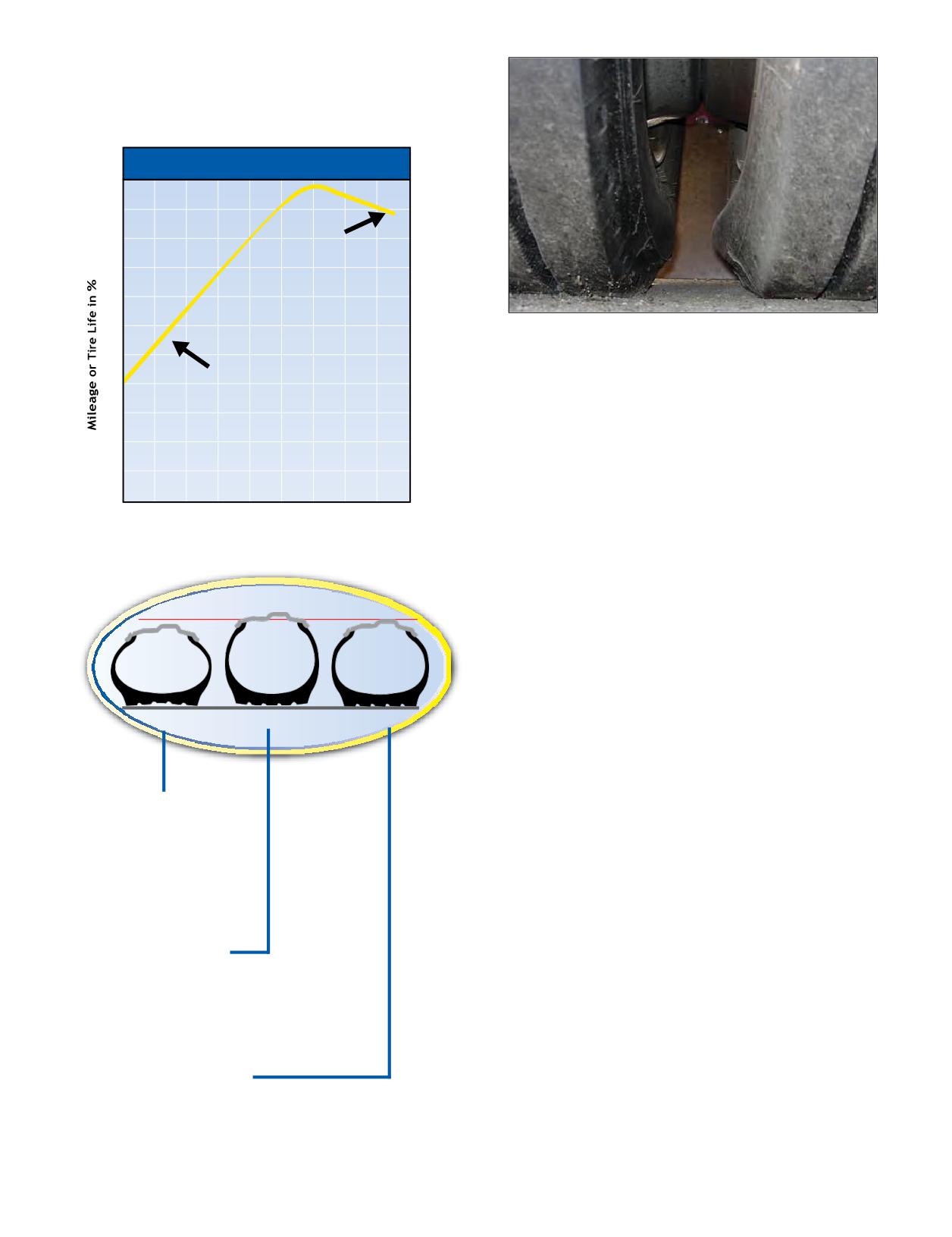
NOTE: The following illustration is based on the
recommended inflation pressure from the data book for
the load being carried.
Effect of Inflation Pressure on Tire Life
100
90
Loss of Service
Due
to Overinflat
ion
80
70
60
Mismatched pressure in dual position will cause
the tires to rotate at different revolutions per mile
50
resulting in irregular wear and tire damage.
Loss of Service Due
40
to
Und
erinflation
30
NOTE: Due to the unique casing design of the MICHELIN®
20
X One® tire, traditional pressure adjustment practices for
dual tires may not apply to the MICHELIN® X One® tire
10
product line. For additional information, see Page 94,
0
Section Five: MICHELIN® X One® Tires.
40%
60%
80%
100%
120%
% of Recommended Inflation Pressure
It is important to maintain inflation equipment
(compressor, inflation lines, and dryer) so as not to
repeatedly introduce moisture into the tire, thereby
accelerating oxidation effects to the tire and wheel.
Under-
Over-
Proper
Inflation
Inflation
Inflation
Tread Contact With Road
UNDERINFLATION
Causes abnormal tire
deflection, which builds
up heat and causes
irregular wear. Similar to
the wheel being too wide.
OVERINFLATION
Causes tires to run hard and be more
vulnerable to impacts. It also causes
irregular wear. Similar to the wheel
being too narrow.
PROPER INFLATION
The correct profile for full contact with the road promotes
traction, braking capability, and safety.
Section Four: Extending Tire Life
51
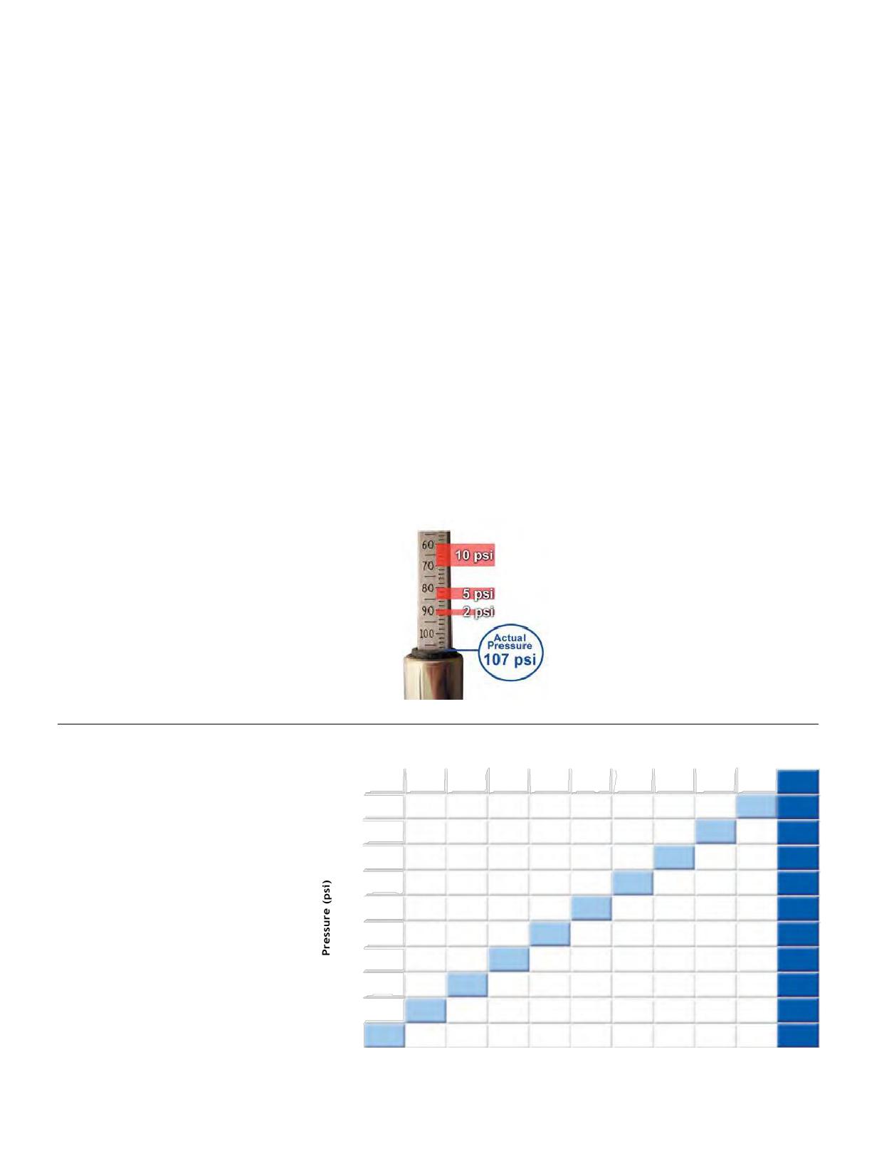
HOW TO PROPERLY MEASURE PRESSURE
NITROGEN
The first step in properly measuring the MICHELIN®
Nitrogen is a very dry inert gas which makes up
X One® tires is to have an accurate pressure gauge.
approximately 78% of the air around us and can be effected
Pressure gauges should be checked weekly against
by humidity. Tires inflated with a normal air compressor
a master calibrated pressure gauge. Tire Billy’s and
already contain 78% nitrogen. Increasing the nitrogen
Thumpers are not considered accurate tire gauges!
percentage to 100% with a nitrogen inflation system will
Sometimes, reading the gauge can present difficulties
not adversely affect the inner liner of the tires nor the
if personnel are not properly trained. Spend the time
performance of the tires under normal operating conditions.
to explain to your personnel the increments on the
While there are advantages for industrial and large off-the-
gauge and how to properly read pressure. It is highly
road earthmover tires, the advantage in commercial truck
recommended that you use a real tire and let the trainee
products is difficult to verify. Moisture, rather than oxygen,
take the pressure and tell you what it reads.
is the bigger concern for casing degradation. Using good
Proper pressure maintenance is critical to obtain
equipment (compressor, inflation lines, and dryer) will
optimized performance from the MICHELIN® X One®
reduce the moisture content of the air in the tire. Moisture,
tires. As part of the pre-trip inspection, it is recommended
when present in the tire, greatly accelerates the oxidation
that the MICHELIN® X One® tires are checked daily with
effects to the tire and wheel. The introduction of even a
an accurate tire pressure gauge.
small amount of normal air will negate the advantage of the
Check all tires when cold; at least 3 hours after the
intended use of 100% nitrogen. If a nitrogen system is to
vehicle has stopped. Never bleed tire pressure from hot
be utilized, Michelin would recommend it be installed by
tires.
trained personnel using appropriate equipment and safety
Underinflation can lead to:
guidelines. Regular pressure maintenance remains critical,
• Adverse handling conditions
and tire inflation check intervals should not be extended due
• Zipper ruptures
to nitrogen use.
• Casing fatigue and degeneration
• Irregular wear
• Decreased tread life
• Reduced fuel economy
Overinflation can lead to:
• Adverse handling conditions
• Reduced resistance to impacts and penetrations
• Increased stopping distances
• Irregular wear
• Decreased tread life
TEMPERATURE/PRESSURE
100
RELATIONSHIP GRAPH
99
This graph displays the reason
98
behind checking your tires when
97
cold. As ambient temperature
increases, pressure increases.
96
An increase in ambient and/or
95
operating temperature will result
94
in an increase in tire pressure.
Checking the tires when hot
93
will result in an elevated reading.
92
A good field thumb-rule to use is
91
that for every 10-degree F increase
in temperature above 65, the tire’s
90
pressure will increase 2 psi.
65
70
75
80
85
90
95
100
105
110
115
Ambient Temperature (Degrees F)
52 Section Four: Extending Tire Life
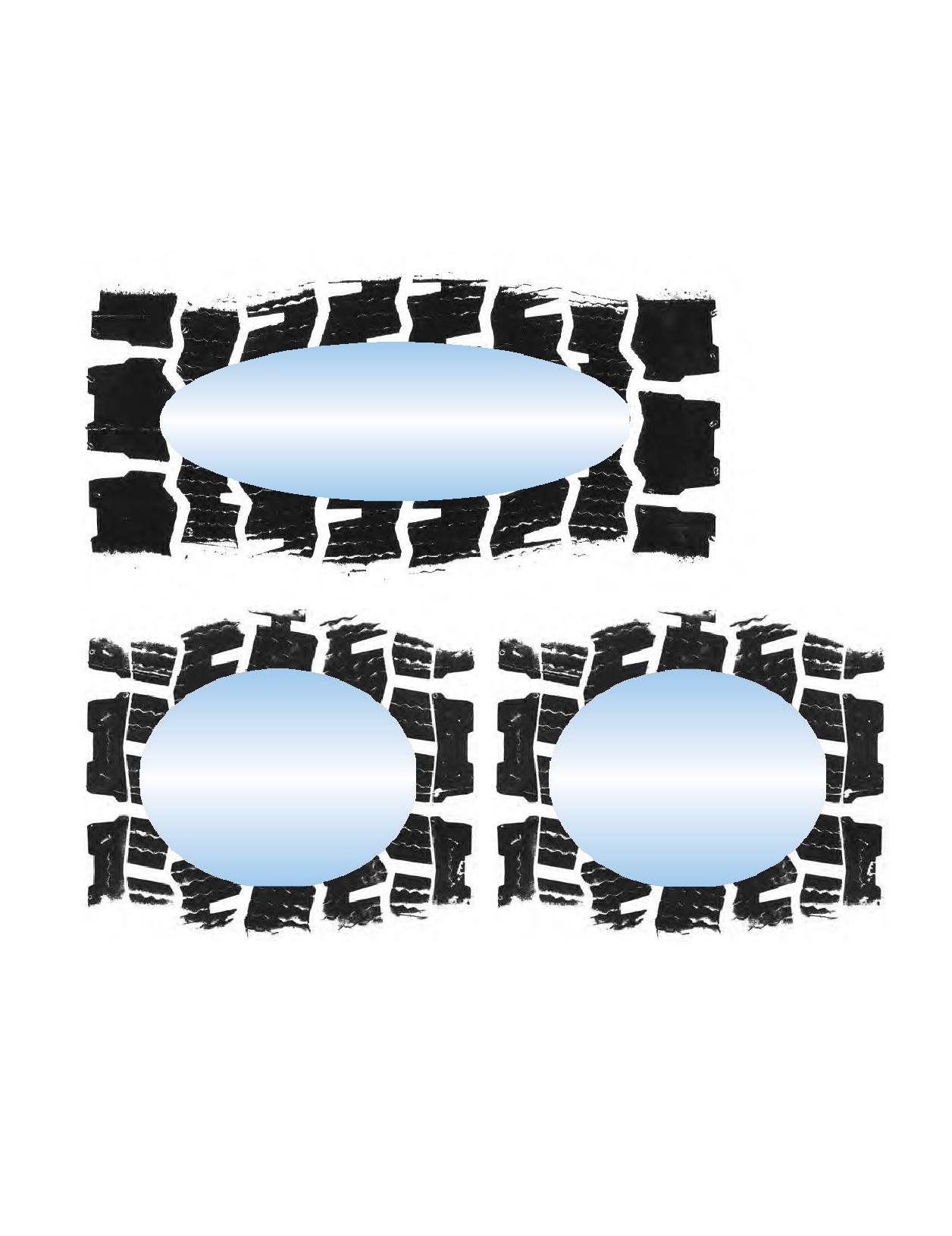
FOOTPRINT COMPARISONS TO DUAL TIRE FITMENTS
Take notice that switching to single tire fitments causes
support the loads your fleet encounters as defined in
a slight reduction in footprint area when compared to
the MICHELIN® Truck Tire Data Book (MWL40731).
dual. This will not have a negative impact on your traction.
Overinflation of the MICHELIN® X One® tires will not only
The MICHELIN® X One® tire footprint will be dependent
reduce the footprint but can adversely affect handling,
on pressure recommendations and vehicle loads. One
wear, and ride characteristics. Overinflating tires may also
should always select a pressure that will adequately
result in exceeding the wheel’s maximum pressure.
FOOTPRINTS: MICHELIN® X ONE® XDN®2 445/50R22.5 VERSUS MICHELIN® XDN®2 275/80R22.5
Unloaded - 8,500 lbs/axle
Loaded - 17,000 lbs/axle
Unloaded - 8,500 lbs/axle
Unloaded - 8,500 lbs/axle
Loaded - 17,000 lbs/axle
Loaded - 17,000 lbs/axle
Section Four: Extending Tire Life
53
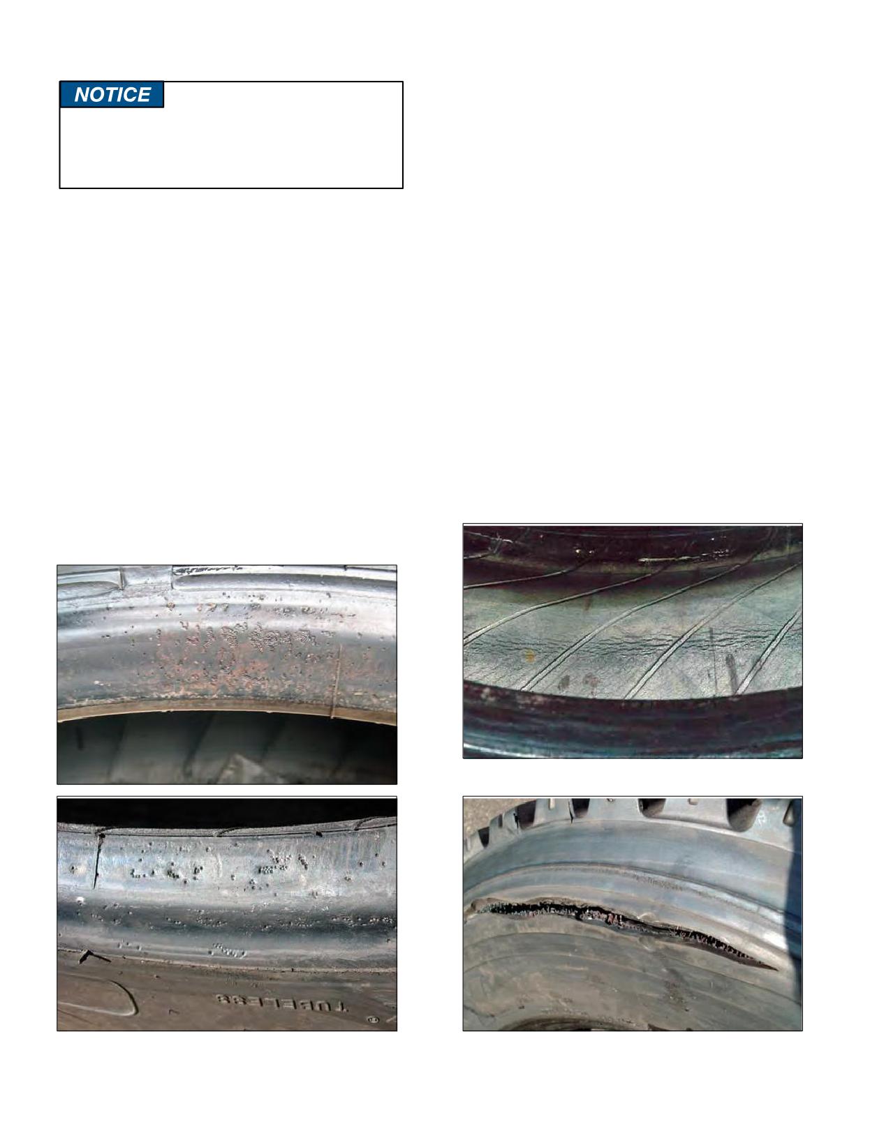
SEALANTS - FOREIGN MATTER IN TIRES
TIRE INSPECTION
While checking inflation pressures, it is a good time to
inspect your tires. If you see any damage to your tires or
Please check with Michelin prior to using
wheels, see a Michelin Truck Tire dealer at once.
sealants or compounds in any MICHELIN®
tires
Before driving, inspect your tires, including the spare,
that have sensors in them. They may adversely
and check your pressures. If your pressure check indicates
affect the performance of the sensors.
that one of your tires has lost pressure of 4 psi or more,
look for signs of penetrations, valve leakage, or wheel
The use of sealants in MICHELIN® Truck Tires does not
damage that may account for pressure loss.
automatically nullify the warranty agreement covering the
If the tire is 20% below the maintenance pressure, it
tires.
must be considered flat. Remove and inspect for punctures
If the sealant has been tested and certified by the sealant
or other damage. If run-flat damage is detected, scrap the
manufacturer as being safe for use in tires, then the
tire. Refer to TMC RP 216C/219C, Radial Tire Conditions
warranty agreement will remain in effect.
Analysis Guide.
If it is determined that the sealant adversely affected the
Tires should be inspected for bulges, cracks, cuts, or
inner liner and/or the performance of the tire, then the
penetrations. If any such damage is found, the tire must
warranty agreement may be nullified.
be inspected by a Michelin Truck Tire dealer at once.
Please refer to the MICHELIN® Truck Tire Operator’s
Use of a damaged tire could result in tire destruction,
Manual and Limited Warranty (MWE40021)for what is and
property damage and/or personal injury.
is not covered by the warranty. If you have any questions,
Equipment that has been out of service for an extended
please contact Michelin at 1-888-622-2306 or refer to
period of time should have the tires inspected for ozone
www.michelintruck.com for warranty information.
damage and proper inflation. The vehicle should have
If foreign matter is installed in any tire, be careful not to
some moderate operating service prior to being put in full
contaminate the bead, and be sure to advise any personnel
service operation.
working with the tire to exercise due caution.
Sign of Run-flat Damage - Interior
Deterioration from Foreign Matter Between the Wheel
Zipper Resulting from Run-flat Condition
and Bead
54 Section Four: Extending Tire Life
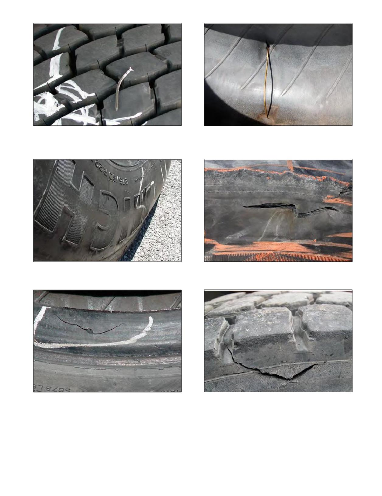
Inspect for Penetrating Objects
Example of sidewall penetration that damaged interior
at crown. Road hazard damages should always be
inspected on the inside and not repaired from the
outside.
Sidewall Abrasion
Sidewall Damage from Impact
Bead Damage
Sidewall Area Damage
Section Four: Extending Tire Life
55