MICHELIN TRUCK TIRE. SERVICE MANUAL (2017) - page 2
AUTOMATED TIRE INFLATION SYSTEM
of the Automated Tire Inflation System (ATIS) will only
come on if the pressure in the tire drops below a certain
(ATIS) OR TIRE PRESSURE MONITORING
percent (usually 10%) of the regulated preset pressure. Even
SYSTEM (TPMS)
when the pressure drops below this point, the light will go
Maintaining proper tire inflation will help maximize tire
off if the system is able to restore and maintain the preset
life and casing durability. This can result in reduced overall
pressure.
tire costs, downtime, tire replacement, irregular wear,
If you have any questions, please contact Michelin
wheel replacement, road debris, and the natural resources
Consumer Care at 1-888-622-2306.
required to manufacture tires and retreads. Correct
inflation will help increase benefits such as fuel efficiency,
safety, driver retention, and uptime, all of which have a
DRIVE CAREFULLY
direct effect on cost per mile.
All tires will wear out faster when subjected to high
While these systems may reduce tire labor, it is still
speeds as well as hard cornering, rapid starts, sudden stops,
necessary to inspect tires to ensure they are serviceable,
and frequent driving on surfaces that are in poor condition.
properly inflated, and the systems are working correctly.
Surfaces with holes and rocks or other objects can damage
All of these systems need to be properly installed and
tires and cause vehicle misalignment. When you drive on
maintained to deliver the benefits they provide.
such surfaces, drive on them carefully and slowly, and
Most of the systems on the market are capable of
before driving at normal or highway speeds, examine your
maintaining a cold inflation pressure within the capacity
tires for any damage, such as cuts or penetrations.
of the truck’s air system. The use of these systems does not
nullify the MICHELIN® Truck Tire Operator’s Manual and
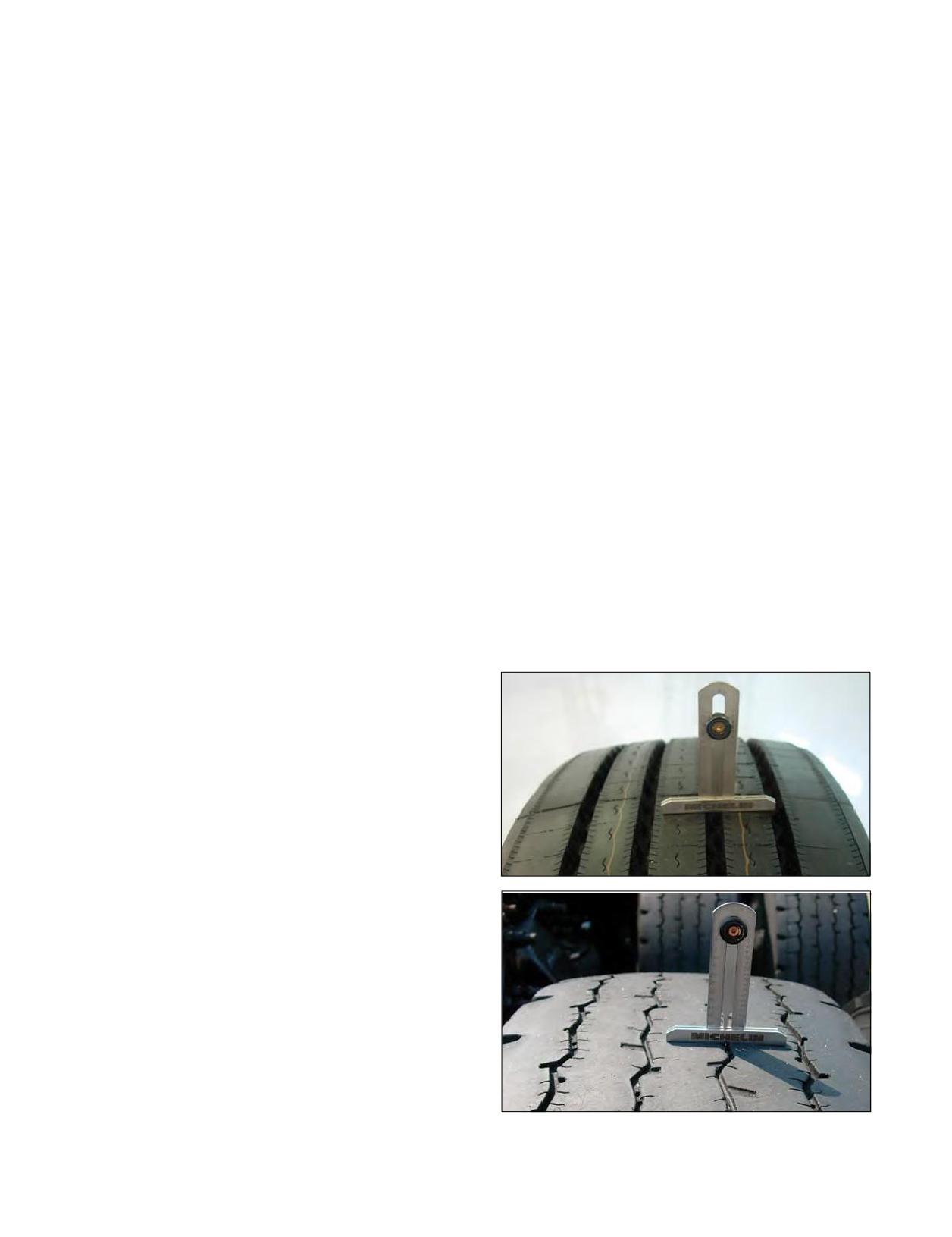
TREAD DEPTH MEASUREMENTS
Limited Warranty (MWE40021) unless it is determined that
Tires should be measured for wear. This measurement
the system somehow contributed to the failure or reduced
can be taken in several spots across the tread and around
performance of the tire. Proper pressure maintenance is
the circumference. However, to calculate the remaining
important for the optimized performance of the tires, so
amount of rubber (knowing the new tire tread depth) for
it is important to make sure the system can maintain the
a given number of miles run, the measurement should
pressures needed and/or can detect accurately when the
always be taken at the same spot on the tread and should
pressures are outside of the normal operating range(s) for
be taken close to the center of the groove, in order to not
the loads being carried. Some inflation systems will add
get a false reading due to the radius of the groove bottom,
pressure when cold weather temperature drops the psi
as shown below.
below that which the system is calibrated for, resulting in a
pressure higher than the target setting. For example,
a 40 degree temperature drop will reduce pressure readings
by 6 to 8 pounds psi, thus the inflation system will increase
the pressure above the target by a like amount. Tires on
vehicles with these systems should still be gauged weekly
and cold pressure adjusted if necessary.
Michelin does not and cannot test every system that
is being marketed/manufactured for effectiveness,
performance, and durability. It is the responsibility of the
system manufacturer to ensure that the tires are inflated
as rapidly as possible to the optimal operating pressure in
order to prevent internal damage to the tires. In view
of the increasing promotion for the use of pressure
monitoring and/or inflation systems, Michelin strongly
urges the customer to put the responsibility on the system’s
manufacturer to prove and support their claims. Please
refer to the MICHELIN® Truck Tire Operator’s Manual and
Limited Warranty (MWE40021) for a general discussion of
what is and is not covered by the warranty.
Systems on trailers can sometimes allow slow leaks
caused by nails or other small objects penetrating the
crown area of the tire to go undetected. A slow leak can be
compensated for by the inflation system. The warning light
56 Section Four: Extending Tire Life
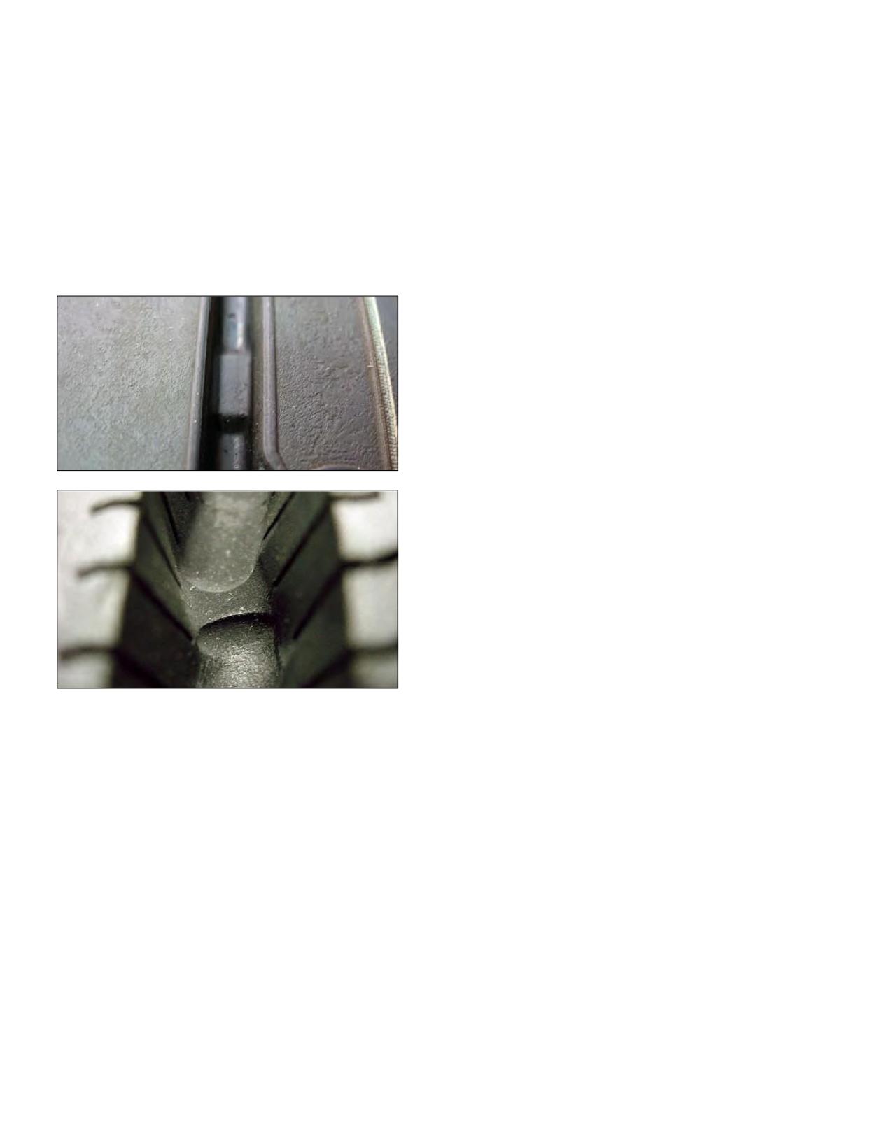
WEAR BARS
data for overall width or the width as marked on the
MICHELIN® truck tires contain “wear bars” in the tread
sidewall of the tire (which may require conversion from
grooves of the tire tread, which show up when only 2/32nds
Metric to English units). It is recommended to contact your
of an inch or less of tread remains. Tread depths should
state’s DOT office to confirm the current Load Per Inch
not be taken on the wear bar indicators. When the tread is
Width Law.
worn level with the wear bar indicators (from either even
For example, if a state allows for 550 pounds per inch
or irregular wear), the tire must be removed from service.
width, a tire marked 11R22.5 could carry up to 6,050
Federal law requires that “any tire on the front wheels of a
pounds (11 x 550) or a total of 12,100 pounds on the steer
bus, truck, or truck tractor shall have a tread groove pattern
axle (2 x 6,050). Another way to look at it is to take the total
depth of at least 4/32 of an inch when measured at any
weight carried and divide by the stated Inch Width Law
point on a major tread groove. The measurements shall not
to determine the appropriate size tire. If a commercial
be made where tie bars, humps, or fillets are located.”
front end loader (sanitation vehicle) wants to carry 20,000
pounds in a state with a 600 pound per inch width limit
(20,000/600 = 33.3), you would need a tire that is at least
16.7 inches wide (33.3/2). In this case a 425/65R22.5 could
legally carry the load (425/25.4 = 16.7 inches Metric to
English conversion).
The two formulas are:
- Load Per Inch Width Law x tire section width x number
of tires = gross axle weight limit
- Gross axle weight / Inch Width Law / number of tires =
minimum tire section width needed
Do not exceed the gross axle weight ratings (GAWR) for any
axle on the vehicle.
Do not exceed the maximum pressure capacity of the
wheel. Consult the wheel manufacturer in these cases.
DRIVE AT PROPER SPEEDS
The maximum continuous speed at which MICHELIN®
truck tires can be operated is indicated in the MICHELIN®
data books. See Section Ten, Appendix under Publications,
Videos, and Websites (Page 186-187) for complete listings
of the MICHELIN® data books. This speed varies for each
type of tire and depends on the type of application. Consult
DO NOT OVERLOAD
Michelin Consumer Care (1-888-622-2306) for assistance
The maximum load that can be put on a truck tire is
in determining the maximum speed for your application.
dependent upon the speed at which the tire will be used.
Exceeding this maximum speed will cause the tire to build
Consult a Michelin Truck Tire dealer or the application data
up excessive heat that can result in sudden tire destruction,
books for complete information on the allowable loads for
property damage, and personal injury. In any case, legal
application. Tires that are loaded beyond their maximum
speed limits and driving conditions should not be exceeded.
allowable loads for the particular application will build up
High speed driving can be dangerous and will likely
excessive heat that may result in sudden tire destruction,
damage your tires.
property damage, and personal injury.
When driving at highway speeds, correct inflation
Some states have enacted “Load Per Inch Width”
pressure is especially important. However, at these speeds,
regulations for the purpose of governing axle weight on
even with correct inflation pressures, a road hazard, for
(primarily) the steering axle of commercial vehicles. These
example, is more difficult to avoid. If contact is made, it
regulations provide a carrying capacity of a certain number
has a greater chance of causing tire damage than at a lower
of pounds per each cross-sectional inch (unloaded) across
speed. Moreover, driving at high speeds decreases the time
the tire’s width. The determination of the tire’s width can
available to avoid accidents and bring your vehicle to a safe
vary from state to state but presumably would be based
stop.
upon either the tire manufacturer’s published technical
Section Four: Extending Tire Life
57

BALANCE AND RUNOUT
It is customary to check tire and wheel assembly balance if the driver makes a ride complaint. Before removing the tire
and wheel assembly from the vehicle, check for radial and lateral runout. Bent wheels, improper mounting, or flat spotting
can cause excessive runout. If balance is still required, a simple static balance with bubble balancer or a wall mounted axle
bearing and hub type gravity balancer should be sufficient. See Section Ten, Appendix for Runout and Vibration Diagnosis on
Pages 176-178.
Current Technology & Maintenance Council (TMC) limits from TMC RP 214D, Tire/Wheel End Balance and Runout, are listed
in the tables below.
TABLE A:
RECOMMENDED BALANCE AND RUNOUT VALUES FOR DISC WHEELS AND DEMOUNTABLE RIMS
Balance
Radial Runout
Lateral Runout
(See Note 2)
(See Note 3)
(See Note 3)
Tubeless Steel Disc Wheels
6 oz. max
0.070 inch max
0.070 inch max
Tubeless Aluminum Disc Wheels
4 oz. max
0.030 inch max
0.030 inch max
Tubeless Demountable Rims
N/A
0.070 inch max
0.070 inch max
Steel
(See Note 1)
0.075 inch max
0.075 inch max
Wide Base Wheels
Aluminum
(See Note 1)
0.030 inch max
0.030 inch max
Note 1: Refer to the manufacturer’s specifications for balance and runout values.
Note 2: Amount of weight applied to rim to balance individual wheel component.
Note 3: For steel wheels, the area adjacent to the rim butt weld is not considered in runout measurements.
TABLE B:
TIRE/WHEEL ASSEMBLY BALANCE AND RUNOUT LIMITS
19.5
Over The Road
On/Off-Road
Wide Base
Tire Positions
Tire/Wheels
Applications
Applications
Tire/Wheels
Maximum total external weight
Steer
12 oz.
14 oz.
16 oz.
22 oz.
correction expressed in ounces of
weight required to correct a rim
Drive/Trailer
16 oz.
18 oz.
20 oz.
26 oz.
diameter per rotating assembly
Steer
0.095”
0.080”
0.110”
0.125”
Lateral runout for
rotating assembly
Drive/Trailer
0.125”
0.125”
0.125”
0.125”
Steer
0.095”
0.080”
0.110”
0.125”
Radial runout
for rotating assembly
Drive/Trailer
0.125”
0.125”
0.125”
0.125”
Note: If tire and wheel assembly is within these limits and ride problem still exists, refer to TMC RP 648, Troubleshooting Ride
Complaints.
58 Section Four: Extending Tire Life
CARE, CLEANING, AND STORAGE
STORAGE
CLEANING AND PROTECTION
All tires should be stored in a cool dry place indoors so
Soap and water is the best solution to cleaning tires.
that there is no danger of water collecting inside them.
If you use a dressing product to “protect” your tires from
Serious problems can occur with tube-type tires when they
aging, use extra care and caution. Tire dressings that
are mounted with water trapped between the tire and tube.
contain petroleum products, alcohol, or silicone will cause
Under pressurization, the liquid can pass through the inner
deterioration and/or cracking and accelerate the aging
liner and into the casing plies. This can result in casing
process. Be sure to refer to the protectant or dressing label
deterioration and sudden tire failure. Most failures of this
contents to confirm that none of these harmful chemicals
nature are due to improper storage. This is a particular
are present.
problem with tube-type tires because of the difficulty in
In many cases, it is not the dressing itself that can be a
detecting the water, which has collected between the tire
problem, but rather the chemical reaction that the product
and tube. When tires are stored, they should be stored in a
can have with the antioxidant in the tire. Heat can make
cool place away from sources of heat and ozone, such as hot
this problem worse. When these same dressing products are
pipes and electric motors. Be sure that surfaces on which
used on a passenger car tire that is replaced every 3 to 4
tires are stored are clean and free from grease, gasoline, or
years, it is rare to see a major problem. In many cases, truck
other substances that could deteriorate the rubber. Tires
tires may last much longer due to higher mileage yields and
exposed to or driven on these substances could be subject
subsequent retread lives, and the chemical reaction takes
to sudden failure.
place over a longer period.
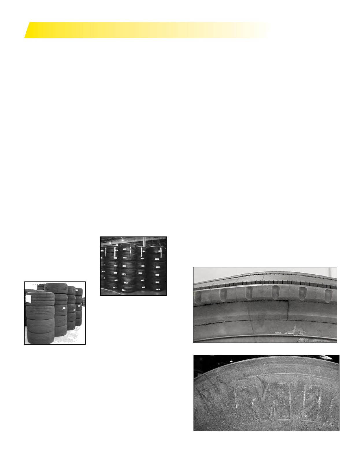
STACKING OF MICHELIN® X ONE® TIRES
DIESEL FUEL CONTAMINATION
Stacking MICHELIN® X One® tires too high could result
Diesel fuel and other petroleum-based products can
in a safety issue and/or could possibly damage the bottom
cause blistering, swelling, or a spongy condition. Swelling
tires.
is typically seen in the tread, and blistering is typically seen
New MICHELIN® X One® tires should never be stacked
on the sidewall. The odor of the petroleum-based product
higher than 3 meters
may be evident. The rubber will also be softer than another
(approximately 10 ft). This
part of the tire with no petrol damage. Generally it may be
will allow the stacking of up
30-40 points softer on the shore hardness gauge. If these
to 6 new tires depending on
conditions are seen or experienced, scrap the tire.
the dimension.
For used and/or damaged
MICHELIN® X One® tires
stacking them more than 5 high
may pose a safety concern.
Swellings in the Tread
FLOOD DAMAGE
Tires that have been subjected and exposed to water from
hurricanes, storms, floods, etc. for a substantial amount
of time need to be discarded and not placed in service
on consumer’s vehicles. This applies to both new tires
(unmounted) in inventory as well as those already mounted
and installed on vehicles. Prolonged exposure to moisture
can have a degenerative chemical effect on rubber and lead
to potential failure later in the tire’s life. If any questions
arise, contact Michelin Consumer Care at 1-888-622-2306.
Sidewall Contamination
Section Four: Extending Tire Life
59
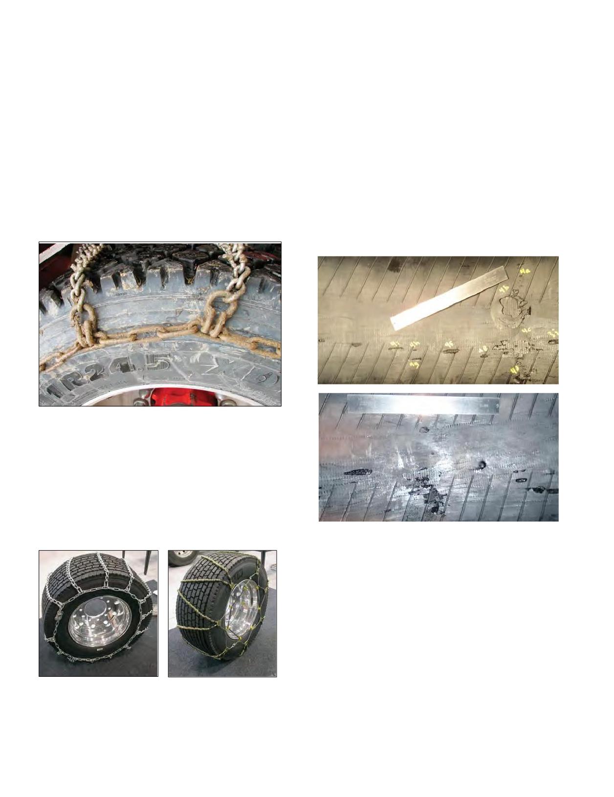
CHAINS*
TIRE DAMAGE RESULTING FROM NON
In order to satisfy legal requirements in many states, you
COMPLIANT RUNFLAT/BEADLOCK DEVICES
may be required to use chains on truck tires. When the
The purpose of this bulletin is to inform end users of
use of chains is required, the following recommendations
the potential for damage from the use of non compliant
should be followed:
devices in tire wheel assemblies.
1. Chains should only be utilized when necessary.
Any device installed inside of a tire/wheel assembly,
The possibility of damage to the tire from the chains will
such as runflat and beadlock devices, must not damage the
increase as driving speed and length of travel increase,
interior surfaces of the tire during normal operation of the
as well as with use on dry pavement. As a general rule,
tire wheel assembly.
chains should be utilized only as long as required, and
Metal, hard plastic, or other non-compliant materials
vehicle speeds should be kept relatively low.
will create damage to the interior surfaces of the tires
2. Since manufacturers have size recommendations
when used in off road and/or reduced inflation pressure
for radial ply tires, no matter what type of chain they
operations of the tire wheel assembly. These damages
manufacture, these size recommendations must be
(as illustrated in the photographs below) will lead to the
adhered to for optimized utility and performance.
tire’s early removal from service, and can result in sudden,
catastrophic failure of the tire.
3. Always be sure to check for proper clearances between
chain and vehicle at the lower 6:00 o’clock position where
the tires deflect due to load. When using tire chains, a
minimum of two inches of space clearance between the
dual assembly and the vehicle is necessary.
4. Also follow closely the mounting instructions and
procedures of the chain manufacturer.
5. Specific chains are available for the MICHELIN®
X One® tire product line.
Damage created by these devices is not a warrantable
condition. Further, these damages may cause the tire to
unexpectedly lose it’s capability to retain inflation pressure.
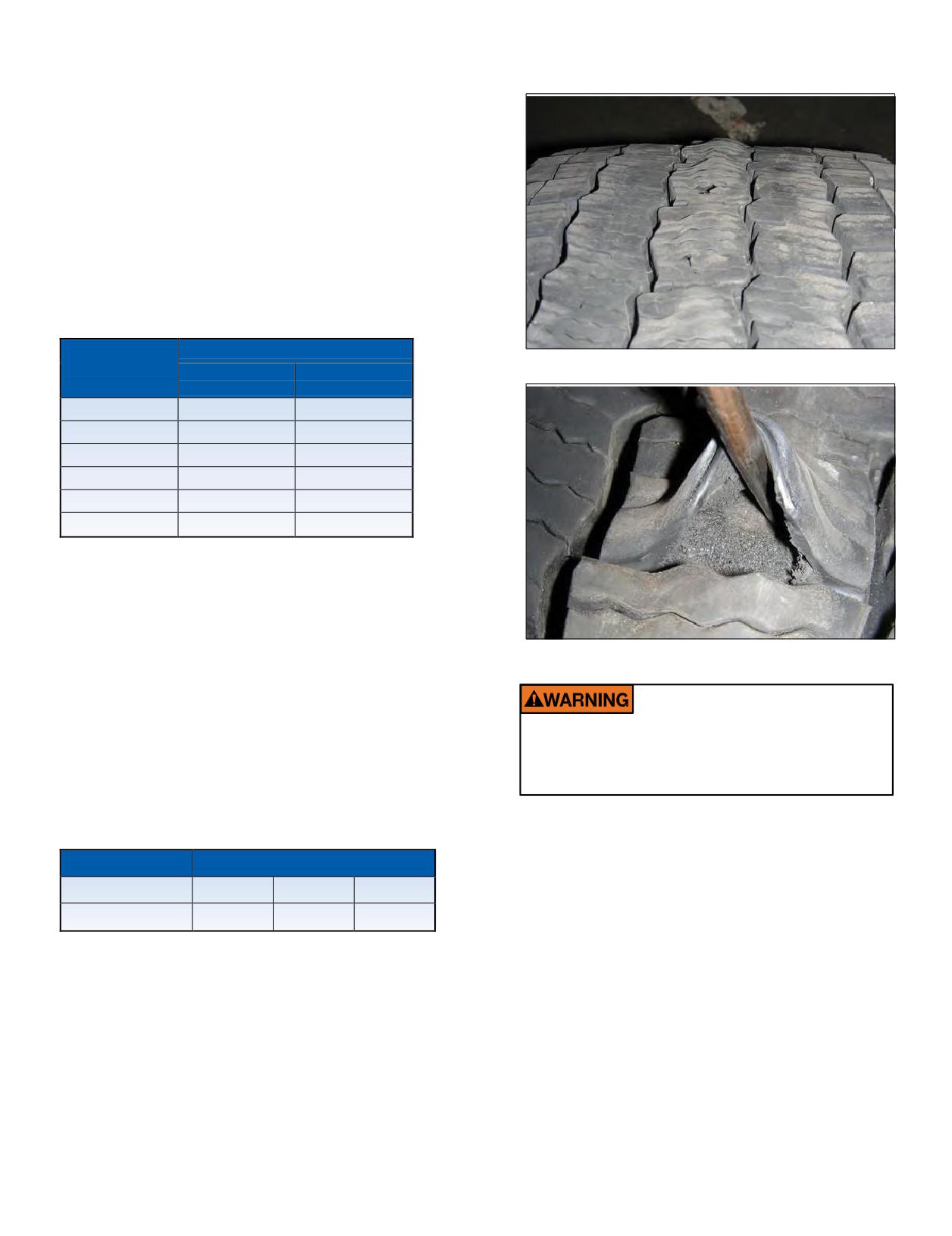
Tire failure may or may not be preceded by bulges, knots,
or blisters on the exterior surfaces of the tire. If a tire
exhibits bulges, knots, or blisters it should be immediately
deflated, removed from service and discarded.
The inclusion of any device or substance inside the air
chamber of a tire/wheel assembly has the potential to
create damage to the tire, please refer to the MICHELIN®
Truck Tire Operator’s Manual and Limited Warranty
(MWE40021) for a general discussion of what is and is not
* The information provided is for reference only.
covered by the warranty.
Chain-specific questions should be directed to the chains
manufacturer.
For additional information, please contact your local
Michelin sales representative or contact Michelin using the
website at www.michelintruck.com.
60 Section Four: Extending Tire Life
RECOMMENDATIONS FOR THE USE OF DYNAMOMETERS
SEVERE DAMAGE can result in the crown area of radial
truck tires when run on dynamometers for extended
periods. Quite often the damage is internal and not
discovered until after the vehicle has been put back in
service.
In order to avoid the possibility of damaging MICHELIN®
radial truck tires, adhere to the following time/speed
restrictions and related test parameters. This applies to tire
sizes with bead seat diameters of 19.5, 20, 22, 22.5, 24, and
24.5 inches.
NOTE: The times for the indicated speed in the chart are
not additive.
MAXIMUM TIME (MINUTES)
Speed (mph)*
On 8 5/8”
On 18-20”
Dia. Rollers
Dia. Rollers
62 (Max.)
2.5
4
50
3.5
6
40
5
8.5
30
7.5
14
20
16
35
10
42
105
*Exceeding the legal speed limit is neither recommended nor endorsed.
Note that in the above speed/time table a significant
increase in time is allowed on the 18-20” versus the
8-5/8” diameter roller. For example, at 30 mph time almost
doubles from 7.5 minutes to 14 minutes.
• Allow a two-hour cool-down between tests.
• These limits are for an empty vehicle with tire pressures
as indicated on the tire sidewall for maximum load.
If these times and/or speeds are exceeded,
• Allow a one-hour cool-down after each test before loading
internal damage in the tire could result,
vehicle.
leading ultimately to tire destruction, personal
The maximum allowable center-to-center distance
injury or death.
between the two rollers in contact with a tire is a function
of the sum of tire and roller diameter.
MAX. ROLLER SPACING
Tire Size
Tire O.D.
8-5/8” Dia.
18” Dia.
275/80R22.5 XZE
40.2”
28”
33.5”
This relationship is shown below:
Maximum Roller Spacing
= Tire Diameter + Roller Diameter x
1.15
2
For example using 8-5 ⁄ 8” diameter:
40.2” + 8.625 x
1.15
2
= 48.825 x 1.15
2
= 24.4125” x
1.15
= 28.07”
Section Four: Extending Tire Life
61
SPINNING
SIPING
Major tire damage can occur in a short period of time
There is no reason to ‘sipe’ new MICHELIN® tires.
when a tire spins on a surface at high speeds. When the
Michelin incorporates siping as needed in its designs
speed difference between the wheel with good traction
to enhance tire performance. Experience suggests
and the wheel without becomes too great, the tire begins
degradation in tread wear, vehicle ride and handling, and
to disintegrate. This can occur on any slick surface (such
tire durability may be caused by poor or improper tire tread
as ice, mud, and snow) or on a dry surface where there is
siping. Drive tires (M/S) are optimized to provide desirable
a variance in traction. The resulting difference in speed of
traction in dry, wet, snow, and icy conditions. Siping does
the assembly can be as high as 4 times the registered speed
not automatically affect the MICHELIN® warranty* that
indicated, resulting in tire and/or differential damage on
covers workmanship and material. However, if a tire fails or
the vehicle.
is rendered unserviceable as a result of ‘siping,’ the tire is
not warrantable.
ROTATION
*See warranty for details.
MICHELIN® radial tires should be rotated when necessary.
If the tires are wearing evenly, there is no need to rotate.
BRANDING
If irregular wear becomes apparent or if the wear rate on
1. The following limits apply when branding MICHELIN®
the tires is perceptively different (from axle to axle for drive
truck tires using equipment without accurate
tires and side to side for steer tires), then the tires should
temperature control or which may exceed 465°F
be rotated in such a manner as to alleviate the condition.
(240°C). (Hand-held equipment is typically used for this
There is no restriction on criss-cross rotation, including
“HOT BRANDING.”)
directional steer tires that have worn 50% or more of the
a. Brand Temperature/Maximum Depth
original tread.
570°F (300°C) 1/64 inch (0.4 mm)
When rotating tires, the following points should be taken
480°F (250°C) 1/32 inch (0.8 mm)
into consideration:
b. Only brand in the “BRAND TIRE HERE” area.
• The load carried by a particular tire in a particular
2. For equipment capable of “COLD BRANDING,” i.e.,
position. The inside tire of a dual mounting carries more
controlled temperatures below 465°F (240°C), the
load than the outside tire on the same axle.
following restrictions apply:
• Adjacent dual tires should not differ more than 1/4”
a. Temperature
Maximum465°F(240°C)
diameter (4/32” tread wear). If there is a difference in
b. Contact pressure
Maximum 100 psi
tread wear, fit the least worn tire in the outside position.
c. Time of contact
Maximum 1 minute
• Curbing on dual applications often damages tire
d. Character Height
Maximum 1 inch
sidewalls. If so, rotate the wheel and tire to the inner
e. Character Depth
Maximum 0.040 inch (1.0 mm)
wheel position.
f. Location:
• Often it is beneficial to rotate the tires so that irregularly
Circumferentially - in the “BRAND TIRE HERE”
worn tires are moved to a position where they are turning
area.
in a direction opposite the original position.
Radially - in the “BRAND TIRE HERE” area with no
portion of any character extending more than
Rotation procedures such as those recommended by
1 inch above the outline of the area.
vehicle manufacturers and those included in TMC RP 642B,
Total Vehicle Alignment Recommendations for Maximizing
Tire and Alignment Related Component Life may be
followed.
Note Directional Tires: When mounting any new
directional tire, ensure directional arrow points toward
the direction of travel during the original 50% of tread life.
Directional casings that have been removed from service
and retreaded should be considered non-directional tires.
62 Section Four: Extending Tire Life
MAINTAINING THE VEHICLE
Many tire problems can be traced to mechanical
• Alignments should be performed carefully using best
conditions in the vehicle. Therefore, to obtain maximized
alignment practices. (For example, ensuring that
tire performance, vehicles must be properly maintained.
the suspension is at the correct ride height and that
the suspension has been settled out by being moved
MAJOR VEHICLE FACTORS WHICH AFFECT
forwards/backwards, etc.)
TIRE LIFE:
• Alignments should be conducted in the most
representative loading condition and ride height for the
expected usage.
ALIGNMENT
Alignment refers not only to the various angles of the
We therefore recommend referring to TMC RP 642B,
steer axle geometry, but also to the tracking of all axles
Total Vehicle Alignment Recommendations for Maximizing
on a vehicle, including the trailer. The dual purpose of
Tire and Alignment Related Component Life, which has
proper alignment is to minimize tire wear and to maximize
established industry recommended target values for the
predictable vehicle handling and driver control. Toe
alignment of vehicles.
misalignment is the number one cause of steer tire irregular
wear, followed by rear axle skew (parallelism or thrust). One
STEER AXLE GEOMETRY
of the challenges of meeting this goal is that alignments are
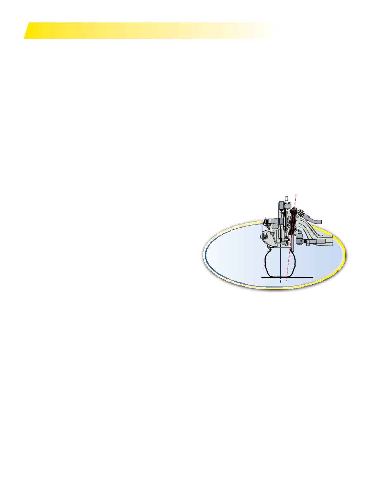
Since very few vehicles continue to use Center Point
typically performed on a static, unloaded vehicle sitting on a
Steering, the following recommendations are based on the
level floor. The vehicle then operates over varying contoured
more common Inclined Kingpin Steer Axle Geometry.
surfaces, under loaded conditions, with dynamic forces
acting upon it. Predicting the amount of change between
static/unloaded/level - versus - dynamic/loaded/contoured
is difficult because many variables affect the amount of
change. Variables such as Steering System Compliance (i.e.
“play”) must be considered in making alignment setting
recommendations.
All of these misalignment conditions may exist alone
Inclined Kingpin
or (more likely) in combination with other misalignment
conditions. Sometimes it is these interactions that produce
the outcomes that are especially undesirable. As an
example, a tire running at slightly negative camber may
perform especially badly if it is also subjected to tandem
thrust misalignment. The conceptual understanding for this
TOE
phenomenon is that because of the camber issue, the wear
Toe is typically the most critical alignment condition
burden imposed by the thrust misalignment is not being
affecting steer axle tire wear. The purpose of setting toe at a
shared equally by the entire tread surface. Further, a tire
given specifi
is to allow the tire to run straight during
that is being operated in a misaligned condition may well
normal operating conditions. Too much toe-in results in
transmit forces into the suspension from its interaction with
scrubbing from the outside inward on both tires, and too
the road. Some suspension systems manage those forces
much toe-out results in scrubbing from the inside outward
favorably. Others react in a way that imposes motions in the
on both tires.
tire that are very unfavorable to the tire’s ability to yield a
Total toe is the angle formed by two horizontal lines
favorable wear outcome.
through the planes of two wheels. Toe-in is when the
• Tires that are not operated at a normal (perpendicular)
horizontal lines intersect in front of the wheels or the wheels
angle to the road surface typically produce uneven
are closer together in front than in back. Toe-out is when
tire wear. Tires that are fighting each other (because
the horizontal lines intersect behind the wheels or the
of conflicting alignment operating angles) produce
wheels are closer together in back than in front. Toe-in is
unfavorable and sometimes irregular tire wear. Tires
commonly designated as positive and toe-out as negative.
that are fighting each other due to highly compliant
Steer axle toe is adjustable to reduce wear to the leading
suspension components (compression/extension in the
edge of the tire and also to avoid road wander. Toe is
bushings or joints, or deflection of solid parts) will likely
adjusted in a static, unloaded condition so that the tires will
produce irregular wear forms.
run in a straight line under a dynamic, loaded condition.
Section Four: Extending Tire Life
63
The toe measurement will probably change from unloaded
TANDEM AXLE PARALLELISM
to loaded condition. The amount of change will vary with
(SKEW - THRUST)
axle manufacturer, axle rating, and steering arm geometry;
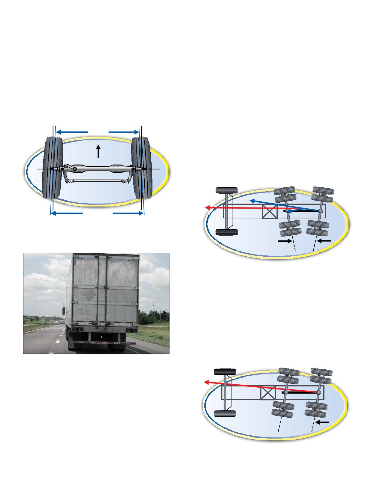
Tandem axle parallelism is critical because it can have
but it is still fairly predictable. Front axles on most popular
a detrimental effect on all ten tires on the tractor. Non-
Class 8 long haul tractors will change in the direction of
parallel drive axles tend to push the tractor into a turn in
toe-out about 1/32” (0.8 mm or 0.05 degree) for each 1000
the direction that the axle ends are closest. In order for the
pounds of load increase on the steer axle. Cabover tractors
vehicle to go straight, the driver must correct by steering in
with set-back-front-axles typically experience less steer
the opposite direction. The vehicle can then go straight, but
axle change in load from bobtail to loaded than do other
all ten tires are at an angle to the direction of travel, causing
confi
Wheelbase and fi wheel location are also
scrubbing. Excessive tandem axle non-parallelism is usually
major factors affecting how much load change the steer axle
detected in steer tire wear. If one steer tire is scrubbing from
will experience.
the outside inward and the other steer tire is scrubbing
from the inside outward, then tandem axle alignment is
Toe-in
suspect. A similar pattern can be generated by the driver’s
compensation for a non-lubricated 5th wheel or from a dog
tracking trailer. This should not be confused with a light
level of toe-in on the right front and lighter toe-out wear on
the left front that may be the result of secondary highway
road crown.
Note: Additional consideration would be effects of air ride
suspension systems, rack and pinion systems, and disc air
brakes on steer tire wear.
Tandem Scrub Angle
THRUST ANGLE (TRACKING)
The relationship of the geometric centerline of the vehicle
and the direction that the axle points generates a thrust
angle. Ideally this relationship would result in a
0 degree value when the axle centerline is perpendicular
to the geometric centerline. However, any deviation from
this setting will increasingly cause the vehicle to travel
away from the straight line, causing the tires to “dog track”
and scrub. Tracking to the right generates a positive thrust
angle; tracking to the left creates a negative thrust angle.
A misaligned (dog-tracking) trailer may also be the
cause of steer tire wear.
See Section Ten, Appendix under Conversion Table
on Page 163 for conversion of fractions in inches to
millimeters and degrees. See Section Ten, Appendix under
Alignment on Pages 164-167 for a field method
for verification.
Thrust Angle
(Tracking)
64 Section Four: Extending Tire Life
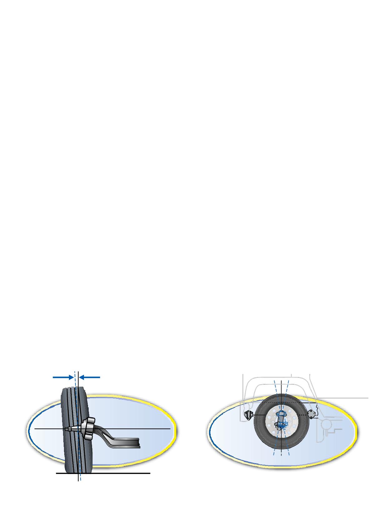
CAMBER
Drive position: Generally, camber is not a major
contributor to drive axle irregular wear, although combined
Camber is the angle formed by the inward or outward tilt
with dual position toe-in or toe-out may cause the onset of a
of the wheel referenced to a vertical line. Ideal camber may
wear pattern.
vary in different applications and in different axle positions
Trailer position: Trailer axles are typically fabricated
as affected by load distribution (i.e. front axle variance of
from steel tubing with spindles welded to the ends. They are
6,000 to 12,000 pounds, drive axle range of 8,000 to 17,000
usually built straight, so there will be some negative camber
pounds, and trailer axle range of 4,000 to 20,000 pounds).
induced when installed under a trailer. Additional loading of
• Camber is positive when the wheel is tilted outward at the
the trailer will cause additional negative camber. Most
top.
trailer axles deflect to about -0.5 degree camber at 17,000
• Camber is negative when the wheel is tilted inward
pounds per axle loading.
at the top.
Camber can accelerate shoulder wear on dual or single
• Excessive positive camber may cause smooth wear on the
tires. Higher degrees of negative camber will show up on the
outer half of the tire tread.
inner shoulder, and positive camber on the outer shoulder.
• Excessive negative camber may cause wear on the inner
Wide single tires seem more susceptible to camber induced
half of the tread.
wear.
• Camber only causes a noticeable “pull” if on the steer axle
Camber correction by bending axles is NOT
the right and left wheel camber angles are not very close
RECOMMENDED by axle manufactures, nor endorsed by
in magnitude (greater than 1/2 degree).
Michelin. Consult the axle manufacturer if camber is found
• Negative camber can also be a cause of inside shoulder
to be incorrect (outside manufacturer specification).
wear on trailer axle in dual or single configuration.
• A free-rolling tire is more sensitive to camber than a tire
CASTER
twisting or turning under the effect of torque.
Positive (+) caster is the backward tilt at the top of the
• A wide tire with a relatively low aspect ratio is more
kingpin when viewed from the side. Negative (-) caster is the
sensitive to camber than a narrow high aspect ratio tire.
forward tilt at the top of the kingpin when viewed from the
• Generally, the vehicle will pull to the side with the most
side.
amount of positive camber.
The purpose of caster is to provide self-aligning forces on
Camber is often a contributor to wear occurring on the
the steer tires to stabilize the vehicle when driving straight
interior ribs/blocks of the inner dual drive tires and can
down the road under braking, free wheeling, and power
sometimes affect the interior ribs/blocks of the outer dual
conditions.
as well.
Insufficient caster reduces stability and can cause
Steer position: Steer axles (which are generally, but not
wander. Excessive caster increases steering effort and can
always, a forged axle) are designed with static unloaded
cause shimmy. Either of these conditions may also have a
positive camber and tend to produce better tire wear when
detrimental effect on tire wear. Excessive caster beyond the
provided with slightly negative camber due to the effects of
vehicle manufacturer’s specification may result in induced
cornering forces, load transfer, and steering Ackerman
camber causing excessive tire wear, particularly fleets that
geometry, which tend to stress and produce outside
are in local and regional operations. Caster is adjustable
shoulder wear during turning maneuvers. In the interest of
with shims. Adjusting only one side is not recommended.
more even overall wear, it is therefore advantageous to let
Caster on both sides should be equal or not more than 1/2
the wear be biased toward the inside shoulder (via slightly
degree difference. Generally, the vehicle will pull to the side
negative camber) during straight ahead driving.
with the least amount of positive caster.
Positive Camber
Positive Caster +
- Negative Caster
0
Section Four: Extending Tire Life
65
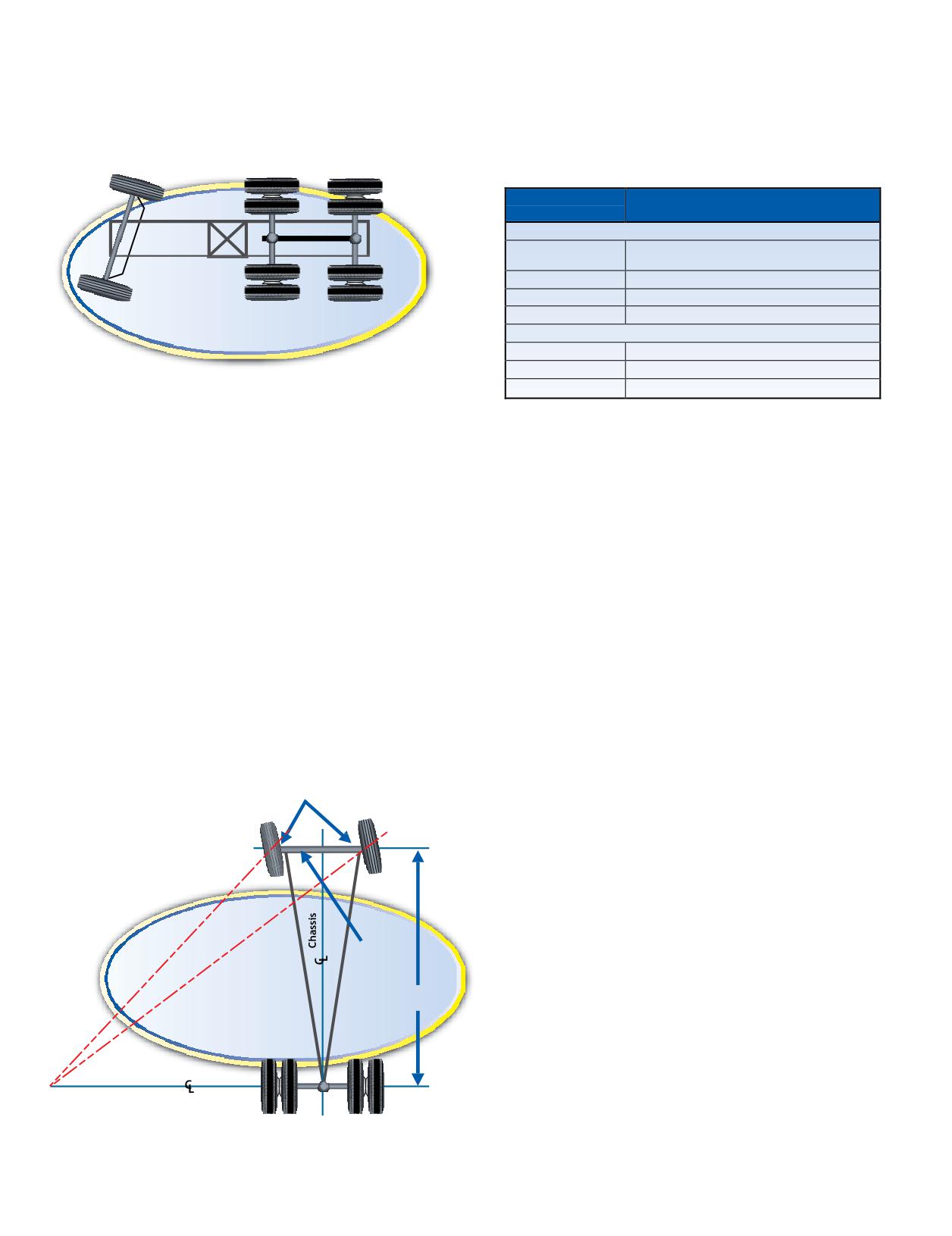
STEER AXLE SETBACK
TMC RECOMMENDED ALIGNMENT
(STEER AXLE SKEW)
TARGETS
Any measured deviation left (negative) or right (positive)
(Value representing industry-established midpoint.)
away from perpendicular to the centerline of the vehicle is
For more information refer to TMC RP 642B, Total Vehicle
called the setback.
Alignment: Recommendations for Maximizing Tire and
Alignment-Related Component Life.
Alignment
Target Value (2)
Specification(1)
Steer Axle
+1/16 inches (0.08 degrees, 0.06 inches,
Total Toe
1.5 mm)
Camber
Less than 1/4 degree (3)
Caster
Left: +3.5 degrees; Right: +4.0 degrees
Steer Axle Setback
Setback
0 degrees / 0 inches
(Steer Axle Skew)
Drive, Trailer, and Dolly Axles
Thrust (Square)
0 degrees / 0 inches
Scrub (Parallelism)
0 degrees / 0 inches
Lateral Offset
0 inches
(1) All specifications are measured with vehicle in static, unladen condition.
(2) All specifications are stated in inches or degrees (where applicable).
TOE-OUT-ON-TURNS
(3) Camber angle changes normally involve bending the axle beam, which may
(TURNING RADIUS)
void the axle manufacturer’s warranty. If the measurement exceeds this value
consult the vehicle, axle, and/or alignment equipment manufacturer.
Toe-out-on-turns is the difference in the arcs described
by the steering tires in a turn. The purpose is to prevent the
inside tire from scrubbing around a turn since the outside
tire (loaded tire) determines the turning radius of the steer
PERIODIC ALIGNMENT CHECKS
axle. This is the Ackerman Principle. Improper geometry
An aggressive alignment preventative maintenance
results in wheel scrub in turns, which generally appears
program should include the following periodic checks:
as toe wear on the tire. More specifically, Ackerman wear
1. Upon delivery of new vehicles. Even though OEMs
shows itself as a rounded edge radial feather wear across the
make a concerted effort to properly align vehicles at the
tread area of the tire. This angle is more important on a city
factory, shifting and settling can occur during delivery.
vehicle with its many turns than on a line haul unit.
Camber and caster may not change much, but toe and
Ackerman geometry is dependent upon the steering axle
tandem axle parallelism may change sufficiently to set up
track-width and wheel base of a vehicle. When the turning
undesirable tire wear patterns if not corrected upon receipt.
angle or wheel base changes from the original specification,
2. At the first maintenance check. Post break-in alignment
Ackerman is affected.
checks should be done between 15,000-30,000 miles, but no
later than 90 days after the first in-service date. If shifting
Steering Arms
and settling did not occur during delivery, it may occur
during the first few thousand miles of operation. Many
OEMs recommend verification of torque on suspension/
frame components after a few thousand miles of operation.
Basic Ackerman Steering Diagram
A thorough alignment check should be made during this
inspection (after torque verification). Consideration should
be given to different torque requirements on metric and
standard bolts.
Cross Bar
(Tie Rod)
3. When new steer tires are installed or front-end
components are replaced. The steer tires coming out of
Wheel
Base
service can tell a story of good or bad alignment. With this
feedback, an alignment program can continue to improve.
Without feedback, the best an alignment program can do is
stay at its current level.
Rear Axle
4. When tire wear indicates a concern. “Reading” tire
Center of Rotation
wear can help identify alignment issues. Unfortunately,
correcting the alignment does not necessarily correct the
tire wear pattern once an undesirable wear pattern has been
established.
66 Section Four: Extending Tire Life
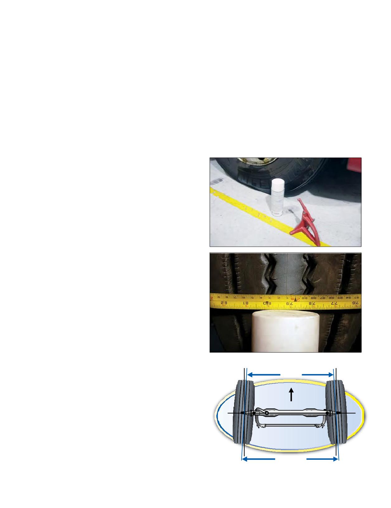
ALIGNMENT EQUIPMENT
A quick field check procedure is done on elevated, dry
tires, and with a can of spray paint or marker, highlight
Alignment equipment exists that ranges from simple
a section of the tread area around the tire. With a sharp
and inexpensive to sophisticated and costly. One factor
pointed scribe, mark a thin line in the highlighted area
that is common to all types of alignment equipment is
while rotating the tire. Repeat this process on the other
that the person using it is extremely important to the
steer tire. Lower the vehicle on folded plastic bags. Once
resulting tire and vehicle performance! Calibration is
the steer tires are down, bounce the truck to make sure
another critical factor in maintaining the accuracy of the
the suspension is relaxed, and verify that the wheels are
system - follow manufacturers’ recommendations. Some
pointing straight ahead. Then measure from side to side
fleets have obtained excellent results with a good “scribe
between the scribed lines, first rear, then front, with a tape
and trammel bar” and paying strict attention to toe and
measure or a fine-lined toe gauge to determine relative
axle parallelism. Other fleets establish permanent records,
toe. Subtract front from rear: positive result indicates toe-
make adjustments more easily, have more information
in, negative is toe-out. See Section Ten, Appendix under
for trouble-shooting, and obtain excellent results with the
Alignment - Field Method (Pages 166-167) for complete
more expensive equipment. The common ground is that
procedures.
the person using the equipment understands it, uses it
properly, and follows the procedures consistently.
Michelin developed the BibAlignment System as a very
simple, accurate, and repeatable method of establishing
the position of a vehicle’s axles relative to each other.
Through the use of a computer program, the highly
portable and cost-effective BibAlignment System calculates
the corrections necessary to improve the vehicle’s axle
parallelism. It locates the centerline of drive and trailer axles
and projects this centerline to the ground. These points
are measured, recorded, and entered into the computer
program. The resulting data concerning the axle alignment
and recommended corrections may be printed for historical
reference. Contact your local Michelin Representative for
ordering information.
Heavy truck alignment has evolved to a precise science.
The “field check” techniques below may be used to detect
a problem condition but are not recommended for making
adjustments/corrections. Proper alignment equipment
should be used if a decision is made to complete this
service.
FIELD CHECK TECHNIQUES
TOE: This wear on the tread occurs due to the shearing
action created by side forces resulting from excessive
toe-in or toe-out. If the toe is properly set, the steer tires
will feel even and smooth when you move your hand across
the tread surface. If the front tires have excessive toe-in, a
Toe-in
feathering wear will be created. This can be felt very easily
with your hand. The tread will feel smooth when you move
your hand in across the tire, but you will feel a drag or
resistance when you move your hand back out across the
tread. If the front tires have excessive toe-out, the opposite
will be evidenced. The resistance will be felt going across
the tread, with no resistance felt while being withdrawn.
A simple Rule of Thumb to remember when analyzing
steering tire wear is “Smooth In” means Toe-In; “Smooth
Out” means Toe-Out.
Section Four: Extending Tire Life
67
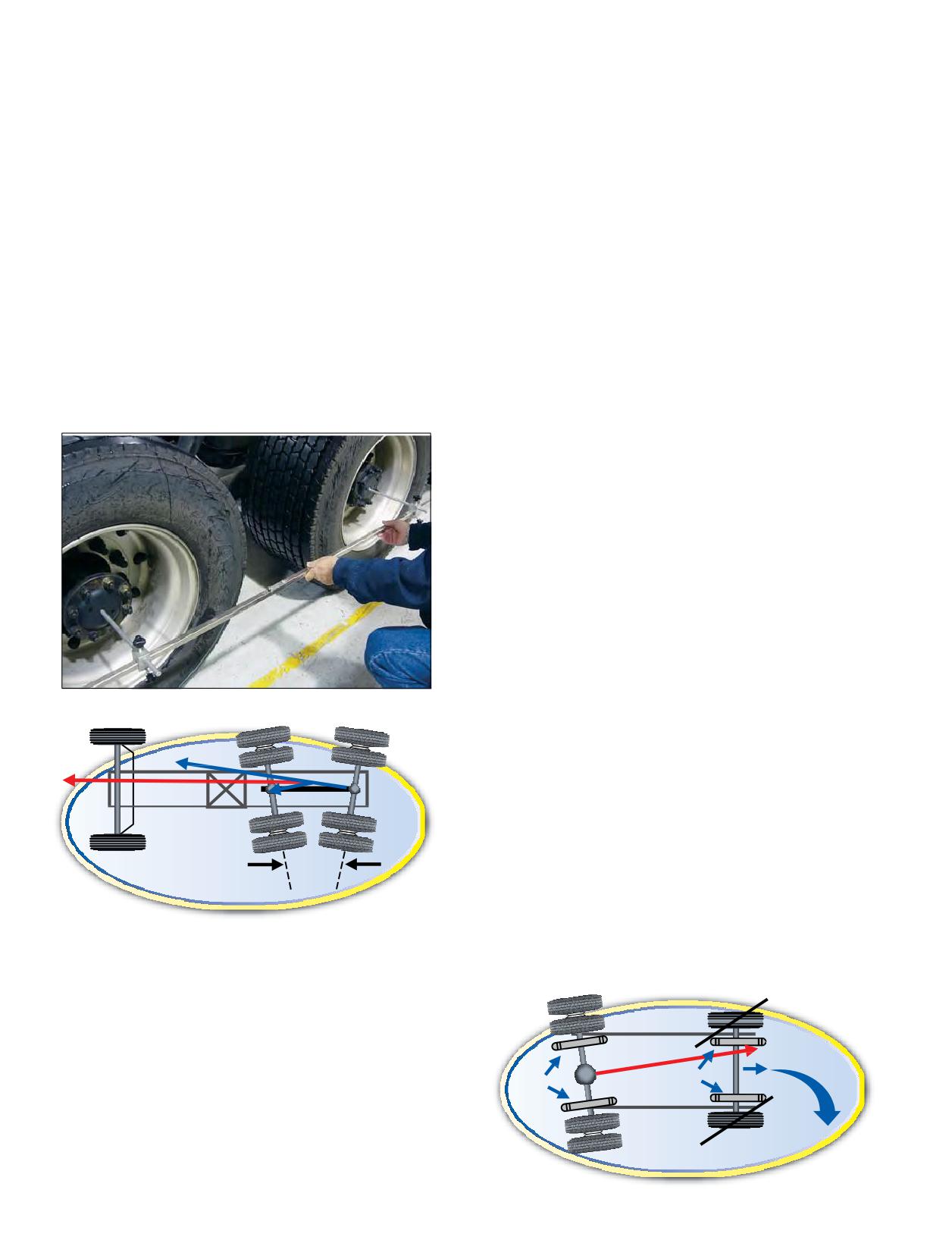
Parallelism: On a tractor with tandem drive axles,
AXLE PARALLELISM AND TRACKING
the two axles should be parallel to one another. Any
In the straight-ahead position, the rear wheels of a vehicle
deviation from this parallel position will create a
should follow the front wheels in a parallel manner. Wheels
tandem skew or scrub angle. This angle should be no
that are out-of-track can cause excessive tire wear. Failure of
larger than one tenth of a degree. An easy method of
the wheel to track is usually due to the following causes:
checking this angle is to measure the distance between
- Master spring-leaf broken
the ends of the axle hubs on each side of the tractor. The
- Incorrect air spring (bag) height
difference between these two measurements should be
- Worn springs
no larger than 1/8 inch for a tandem tractor/truck and
- Auxiliary leaves broken
no larger than 1/16 inch on a tandem axle trailer. The
- Loose “U” bolts
easiest way of accomplishing this measurement is by
- Incorrect or reverse springs
using a trammel bar. The pointers on the trammel bar
- Bent frame
must fit in the axles’ centering holes on both sides of the
- Locating rods or torque rods improperly adjusted
vehicle.
- Locating rod or torque rod bushings worn excessively
For example, if the ends of the drive axles on the left
Failure of the wheels to track is usually quite visible when
side of the vehicle are closer together than the axle ends
one follows the vehicle on the highway. It is possible that, due
on the right side, this will cause the vehicle to pull or
to one of the above causes, no uneven wear manifests itself on
drift to the left.
the rear tires, but an uneven wear pattern may show itself on
the front tires. This is because rear tires may push the vehicle
off course and give some toe-out-on-turns in the straight-
ahead position to the front tires. Hence, the driver makes
a correction to offset the steering action caused by the rear
wheels.
If the rear axle of a vehicle is not at right angles to the
chassis centerline, the front tires are affected, showing
misaligned wear. In the diagram below, the position of the rear
axle of the vehicle has been altered because of a weakened
left side spring - so that the rear axle on the left side is further
from the front axle than the rear axle on the right side.
In this illustration of a 4x2 configuration, the angle of the
rear axle causes its wheels to point to the left side so that the
rear end of the vehicle is, in fact, self-steered in that direction.
The vehicle would then steer itself to the right - unless the
driver takes corrective action. If the driver wishes to travel
straight ahead, he will naturally compensate by turning his
steering wheel. This action introduces a turning moment as
if the vehicle were making a turn although it is moving in a
straight line due to the toe-like posture of the front wheels.
It is more difficult to identify this concept with additional
drive axles and the placement of movable 5th wheels. For this
Tandem Scrub Angle
reason, the onset of misalignment wear patterns on the front
tires may be apparent, even though the lateral forces may be
slight and the front wheel alignment settings may be correct.
Top View
Inside
Wear
Springs
Springs
Outside
Wear
Vehicle Pulls to Right
68 Section Four: Extending Tire Life
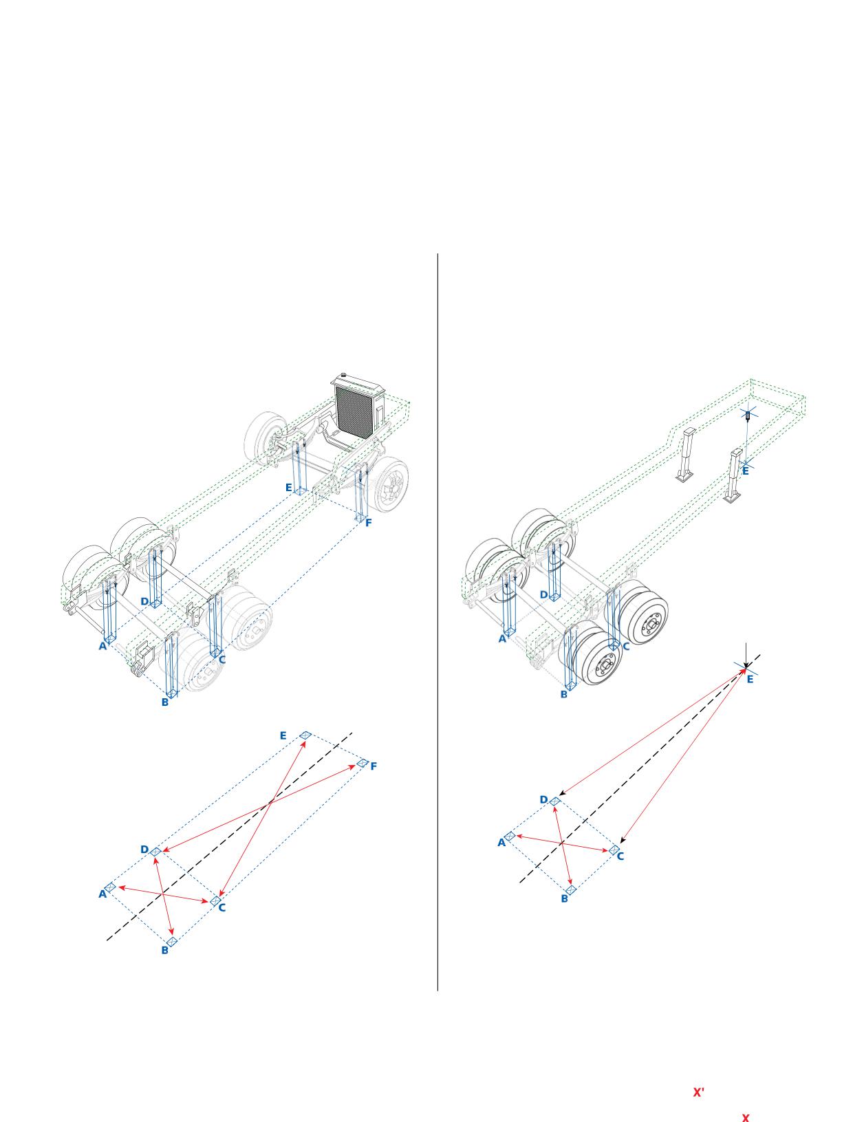
HOW TO CHECK AXLE PARALLELISM AND TRACKING:
With the vehicle on a flat surface and with the suspension in a relaxed position, select two points on the front and rear
axles. These two points on each axle must be equal distance from the chassis center (e.g., at the point where the springs meet
the axles). Using a plumb line, mark four points on the ground, move the vehicle away, and measure the distance between
the marks as shown on the diagram.
A more detailed field type procedure is recommended by Michelin and can be found in the Section Ten, Appendix under
Alignment - Field Method (Pages 166-167).
For Truck/Tractor: The Technology and Maintenance
For Trailers: The Truck Trailer Manufacturers
Council recommends no more than 1/8 inch between axle
Association (TTMA) recommends no more than 1/16 inch
ends. If AD = BC and DE = CF, the axles are parallel.
between axle ends and 1/8 inch maximum from the trailer
If X = X’ and Y = Y’, the wheels are symmetrical or
kingpin to the lead axle ends. If AD = BC and CE = DE, the
tracking.
axles are parallel and symmetrical. (Reference: TTMA RP
No. 71 Trailer Axle Alignment.)
Section Four: Extending Tire Life
69
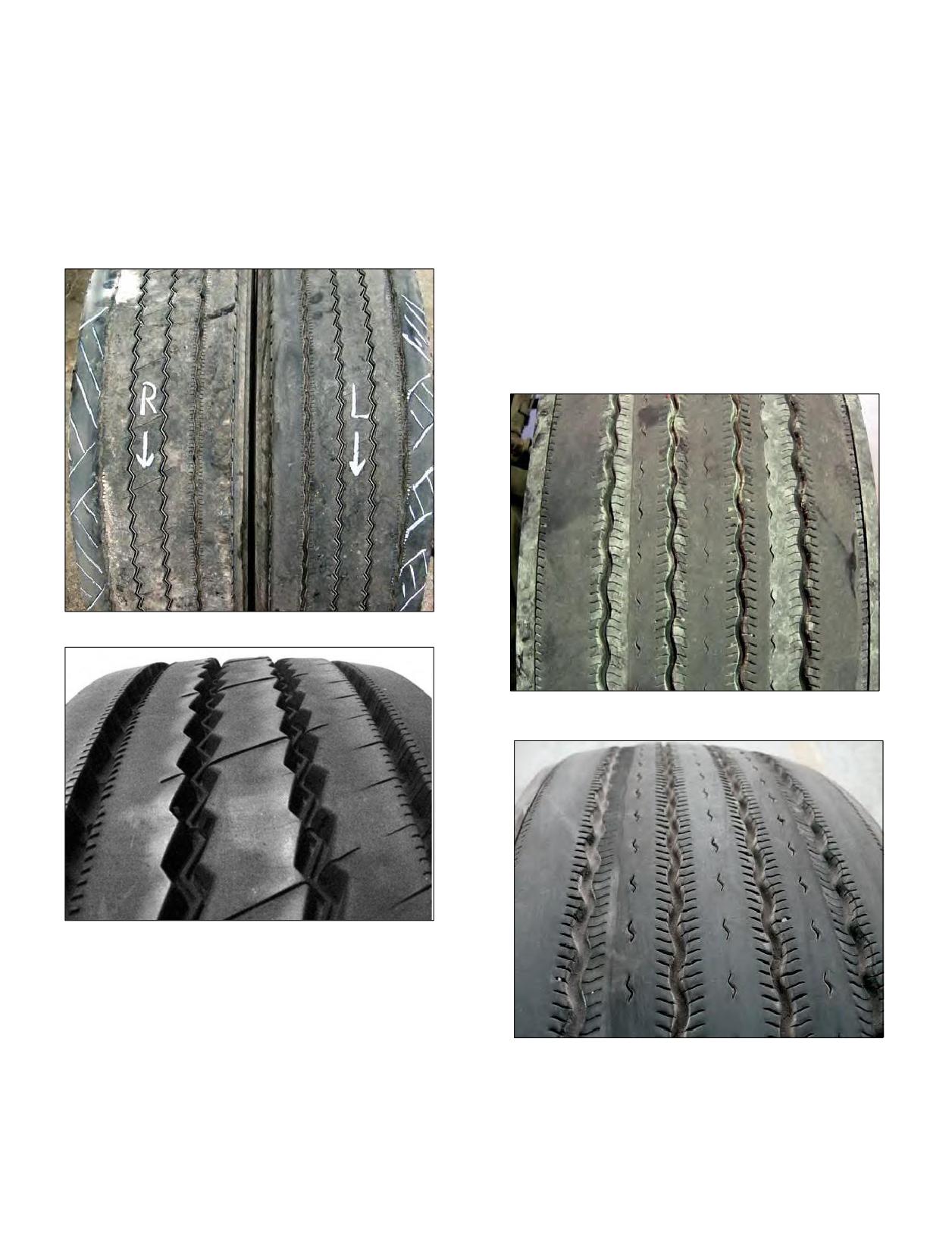
TIRE WEAR PATTERNS DUE TO MISALIGNMENT
It should be noted that some wear patterns might be from multiple causes. Additional information may be obtained
in the TMC RP 216C/219C, Radial Tire Conditions Analysis Guide and www.michelintruck.com/reference-materials/
videos/#/maintenance-and-training about the “Fundamentals of Tire Wear” and “Scrap Tire Analysis.”
Toe Wear - The typical wear pattern that develops from
Free Rolling Wear - Wear at the edge of a rib
excessive toe is a feather edged scuff across the crown.
circumferentially, which may or may not affect the entire
Excessive toe is usually seen on both steer tires.
rib widths. Intermittent side forces due to wheel assembly
instability cause contact pressure variations, resulting in
this type of wear. Generally, due to excessive looseness
in the suspension and/or steering components, this is
also found in slow wearing positions at high mileage.
Insufficient caster and excessive lateral tire/wheel runout
also are contributing factors.
Toe Wear
Free Rolling Wear
Toe Wear
Free Rolling Wear
70 Section Four: Extending Tire Life
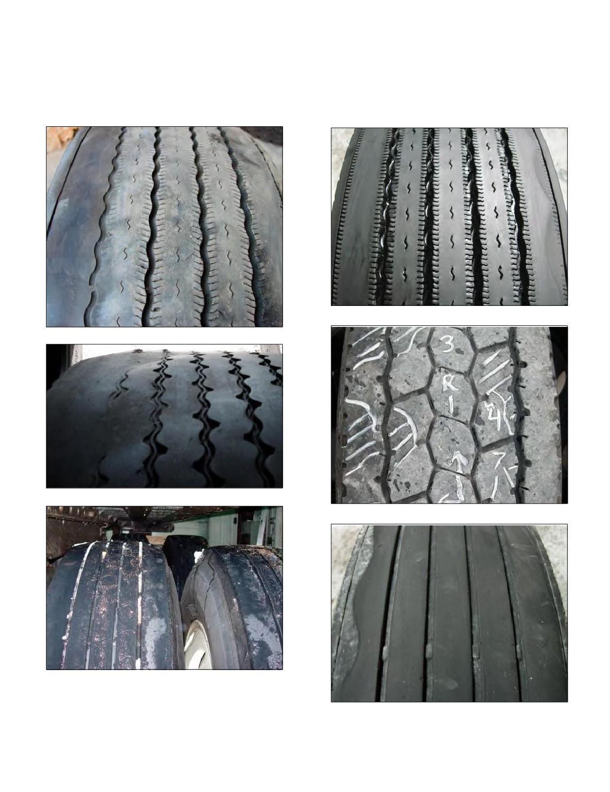
Camber Wear - If the axle has excessive camber,
Cupping Wear - Any loose or worn component in
partial or total wear of the shoulder will occur. For static
truck steering or suspension systems can cause odd
unloaded vehicles, camber readings for steer positions
wear, cupping, and flat spots. Check for loose wheel
should fall within the range of 0 to 1/4 degree positive
bearings, worn shock absorbers, steering gear lash, worn
(0.0 to 2.5 mm), and trailer positions should fall within the
tie rod ends, and kingpins. Check for possible mismount
range of ± 1/4 from 0 degree (± 2.5 mm from 0).
conditions.
Cupping Wear - Steer
Camber Wear - Steer
Camber Wear - Drive
Cupping Wear - Drive
Camber Wear - Trailer
Cupping Wear - Trailer
Section Four: Extending Tire Life
71
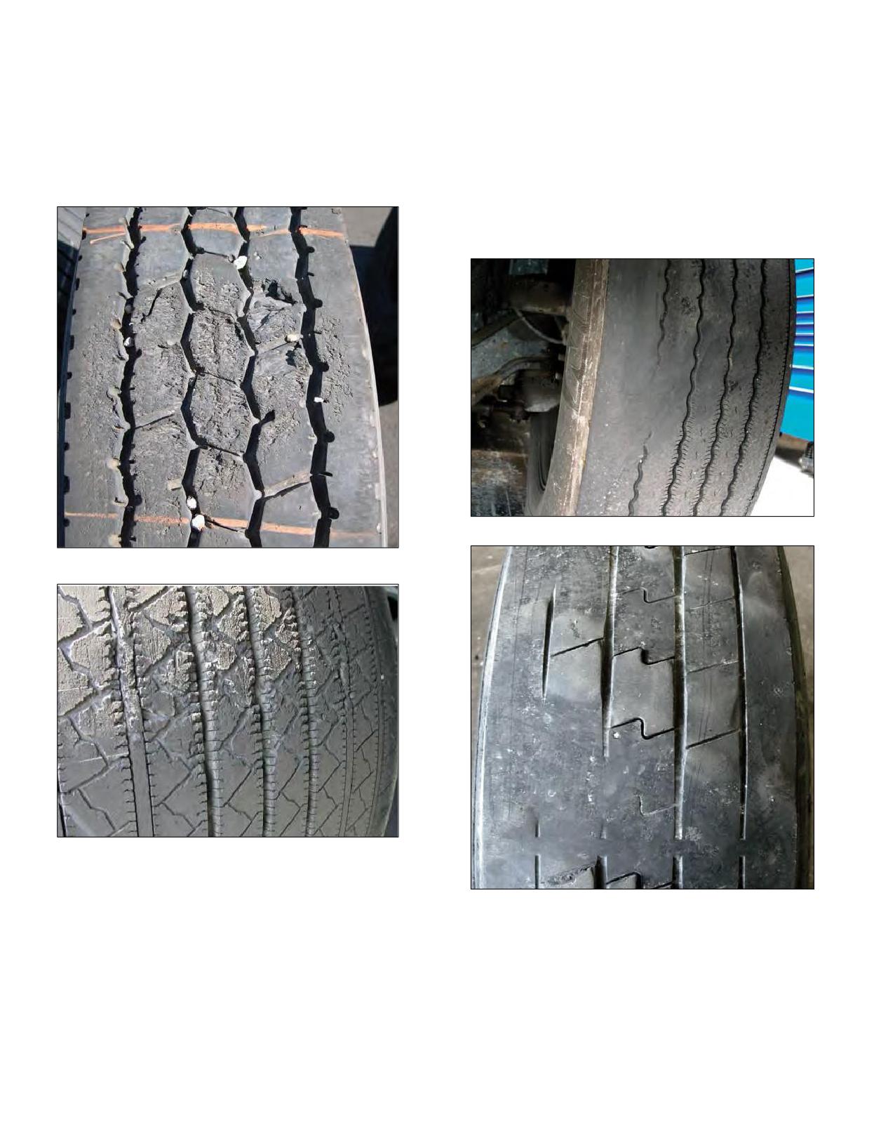
Flat Spotting Wear - Localized wear across the tread
Diagonal Wear - Localized wear diagonally across the
width. Causes include brake lock, brake imbalance, out of
tread width. Side forces imposed by a combination of
round brake drums, axle hop, or skip. A tire being parked
toe and camber create diagonal stress in the footprint of
on a surface containing hydrocarbon oils, chemicals, and
the tire. Localized wear patterns tend to follow this same
solvents can also cause this type of wear pattern. The
direction creating diagonal wear. For steer positions,
affected area of the tread will wear more rapidly, leaving a
causes include excessive toe combined with tandem
flat spot.
drive axle misalignment, incorrect steering angle in turns,
worn parts, and/or excessive camber setting. For trailer
positions, causes include tandem trailer misalignment,
negative camber, and loose or worn components.
Diagonal Wear
Flat Spotting - Drive
Flat Spotting - Trailer
Diagonal Wear
72 Section Four: Extending Tire Life
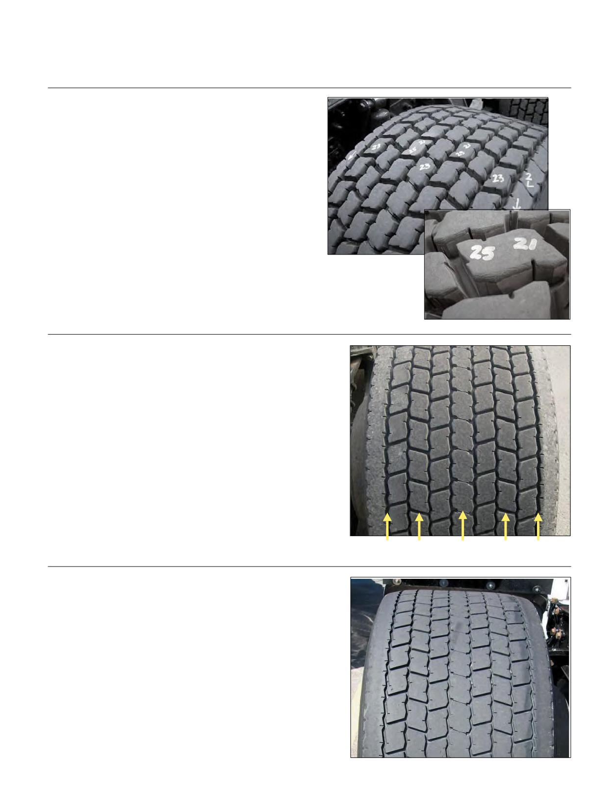
IRREGULAR TIRE WEAR
TRACTOR:
Heel-Toe
Appearance:
Drive-lugs around the tire worn high to low from the front
to back edge on tread of tire.
Probable Cause:
High torque, pickup and delivery operations (P&D) plus
mountainous terrain, high braking operations.
Analysis/Correction:
Drive tires should be rotated, front to rear; cross rotation is
permitted, but will accelerate wear and can reduce removal
Inset: Notice
mileages. With the MICHELIN® X One® tire, since there are
appearance of
no dual pressure differences, heel and toe pattern should
shoulder-scrub
on side of tread-
clear itself up @ 1/3 worn.
blocks inner/outer
shoulders.
Center Wear
Appearance:
Tire wears more rapidly in the center of the tread, than in
the shoulders.
Probable Cause:
LTL (Less than Truckload) operation + high torque,
incorrect pressure.
Analysis/Correction:
Five tread depths should be taken in the drive position,
allowing one to recognize wear conditions.
Correction of drive-axle pressure will reduce the wear
pattern and enhance tire mileage.
13/32” 14/32”
11/32”
14/32” 13/32”
River Wear Only
Appearance:
Tire exhibits circumferential wear along the rib-edges next
to the major shoulder tread-ribs.
Probable Cause:
Characteristic of slow wear-rate of radial tires.
Analysis/Correction:
None, river wear should not be of concern.
Section Four: Extending Tire Life
73
TRAILER:
Step-Shoulder/Localized Wear
Shoulder Cupping
Appearance:
Tire exhibits step-down wear on one or both
shoulders or localized cupped out areas.
Probable Cause:
Incorrect pressure, damaged/bent trailer-axle,
incorrect camber setting, alignment issue, LTL
(Less than Truckload) operation, suspension
compliance.
Analysis/Correction:
Review tire application with tire manufacturer;
review inflation maintenance procedures.
Check trailer alignment for bent or worn parts,
or consult trailer OE.
Left Front Trailer Position
Left Front Trailer Position
(Original)
(Rotated)
Trailer Rotation:
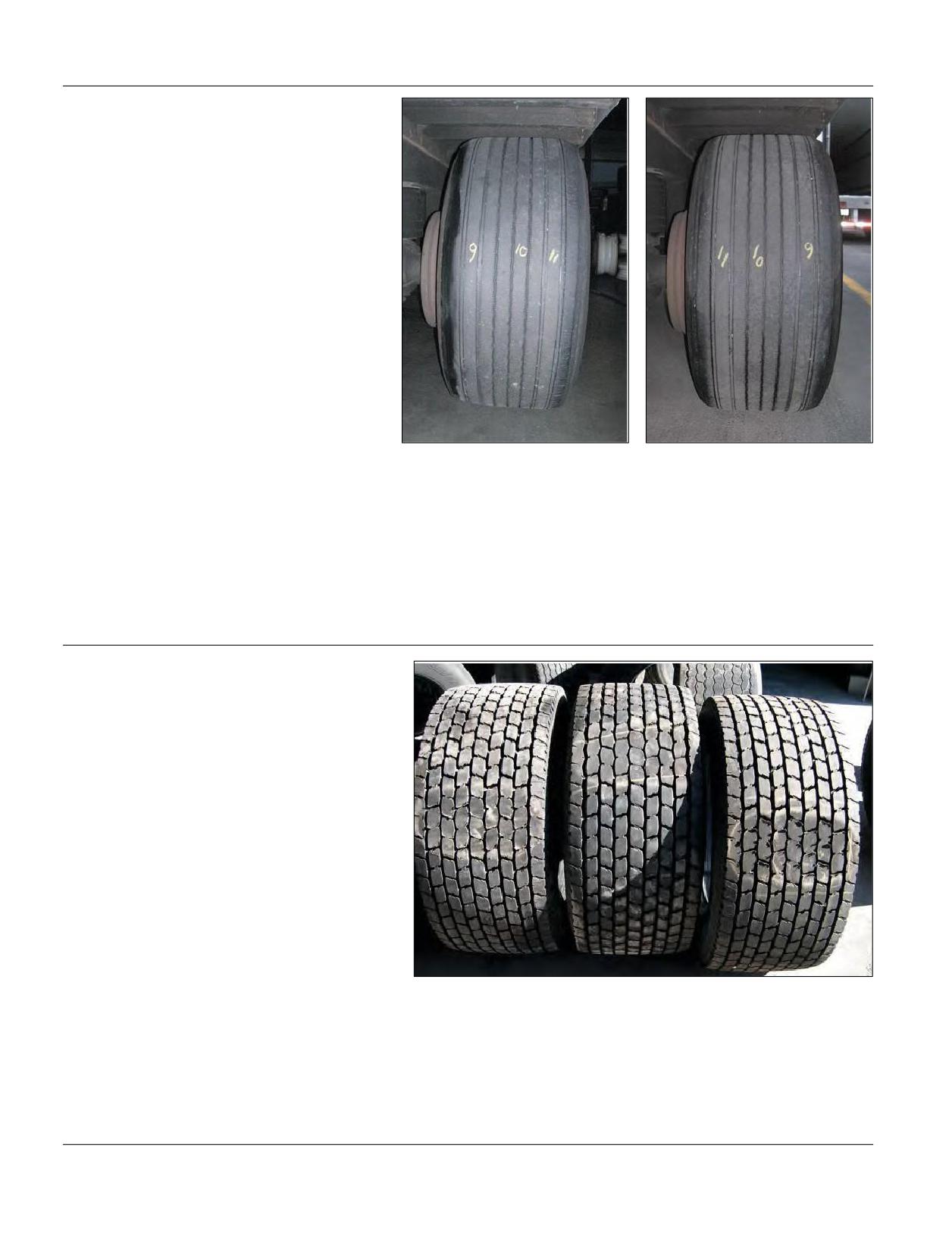
Irregular wear on the inside shoulder of trailer tires can be rectified by flipping the tire on the wheel, where the inner
shoulder becomes the outside shoulder. Criss-cross rotation may also be helpful depending upon 1st and 2nd trailer axle
wear-rates.
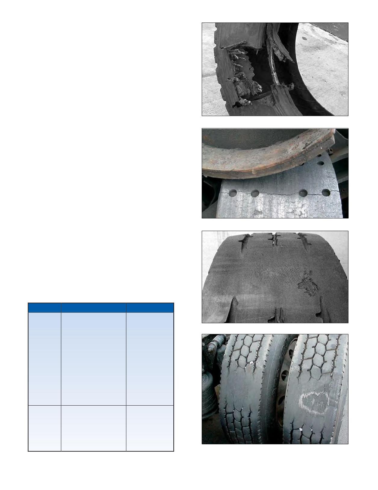
Brake Skid
Appearance:
A tire with brake drag is characterized by localized
abrasion or flat spot if severe. If left in service, it may
continue to grow across the face of the tread.
Probable Cause:
Tractor/trailer moved prior to system pressure
building up sufficiently to release parking brakes:
resulting in dragging the tires or driver over-using
hand or trailer brake.
Analysis/Correction:
Review driver tractor/trailer hook-up and departure instructions. The fleet yard mule driver can be a factor. If they are
in a hurry to move trailers, they may pull away before the pressure has built up sufficiently to release the brakes. If the
flat spotting is minor, leave the tire in service. If tire induces vibration, has exposed steel or is lower than the minimum
required tread depth, remove the tire from service. Even vehicles equipped with anti-lock brake systems (ABS) can
experience flat spotting, depending on the number and placement of sensors and modulators used.
74 Section Four: Extending Tire Life
BRAKING SYSTEMS AND ISSUES
Air brake issues as they apply to tire wear and damages
can result from imbalance or component concerns.
Distorted, brittle, and/or discolored rubber in the bead
area are signs of the “outside to inside” breakdown of
rubber products as a result of seating on a wheel surface,
which is heated to a temperature beyond the limit that
the rubber products can tolerate. This damage starts at
a temperature in the mid-200 degree Fahrenheit range,
with accelerated damage occurring above the 300 degree
Fahrenheit range.
1. Brake imbalance can be the result of the air system,
Brake Heat
including valves, not actuating the brakes simultaneously.
This may be the result of dirt, leaks, and/or valve cracking
pressure. In a tractor/trailer combination, the more rapid
brake application time now being used (up to twice as
fast as pre FMVSS*-121 systems) can result in a brake
imbalance due to combinations of old tractors with new
trailers or new tractors with old trailers.
2.Component situations, such as out-of-round brake
drums or unevenly worn brake shoes, also result in tires
acquiring odd wear and flat spots.
3.Another source of brake imbalance is the improperly
adjusted slack adjuster. Any of these brake imbalance
situations can result in one or more wheel positions
Brake Heat
locking up and flat spotting the tires.
4.Brake drums with balance weights thrown may result
in ride disturbance.
5. Brake lock (flat spots) conditions may be evidence of
deficiency in the Anti-Lock Brake System.
*FMVSS - Federal Motor Vehicle Safety Standards
SUMMARY OF TIRE ISSUES DUE
TO BRAKES
Problem
Possible Causes
Result
1. Overuse on down
grades due to
Brake Lock
improper gear.
Bead damage
2. Brake dragging due
to the tire
to mis-adjustment of
ranging from
wheel bearings.
simple distortion
3. Repeated stops
Brake Heat
to complete
without cooling time.
unwrapping of
4. Improper adjustment
the casing from
or braking balance
the bead wire.
leads to excessive
amount of braking in
one or more wheel
positions.
1. Out-of-round brake
assembly.
Flat spots and
2. Slow release valves.
Lock Up
odd wear.
3. Mis-adjustment, slack
adjusters.
4. Brake drum runout.
Brake Lock
Section Four: Extending Tire Life
75
BRAKE HEAT OVERVIEW
Brake temperatures on trucks often reach very high
temperatures. Brake drums can reach temperatures of
600°F or more and are in very close proximity to the wheels.
This heat can be easily transferred to the wheels and tires.
Brake drum heat is transferred to the wheel primarily
through radiation and convection. The hot brake drum
radiates heat in all directions to the wheel. In addition,
the drum heats the air between the drum and the wheel.
The heated air rises and transfers additional heat energy
to the wheel through convection. Much of the heat is
transferred to the wheel in the bead mounting area due
to its close proximity to the brake drum. The wheel then
Brake Lock on Ice
directly conducts heat to the tire bead resulting in elevated
temperatures in the tire bead area.
Excessive bead heat can affect tire life in many truck
tire applications. Vehicles in urban and refuse service are
most commonly associated with bead heat issues, but any
application that experiences hard braking can be affected.
Brake Lock on Grooved Payment
Duals - Close to Brake Drum
CASING LIFE vs BEAD TEMPERATURE
400
350
300
250
200
150
1
10
100
1,000
10,000
Casing Life (hr)
76 Section Four: Extending Tire Life
Results of bead heat:
The second stage occurs when the rubber in the bead
1. Immediate failure: In some cases, after periods of
area starts to split or crack, indicating that the steel casing
hard braking where brake drums reach very high
plies are starting to unwrap.
temperature (in excess of 600°F), immediate failure can
occur. This normally occurs when a truck is brought
to a stop for a period of time with very high brake
temperatures. Often this occurs when an over the road
truck stops at a truck ramp at the bottom of a long
descent. As the heat rises from the brake drum, there
is excessive heat buildup in the portion of the tire bead
directly above the brake drum (inner bead of inside
dual). The high temperature can cause a breakdown of
the rubber products in the bead area and allow
the steel body cables to unwrap from the bead. This
could result in a rapid tire pressure loss occurrence.
This phenomenon is also common in urban and refuse
fleets when the driver stops for a break after a period of
hard braking.
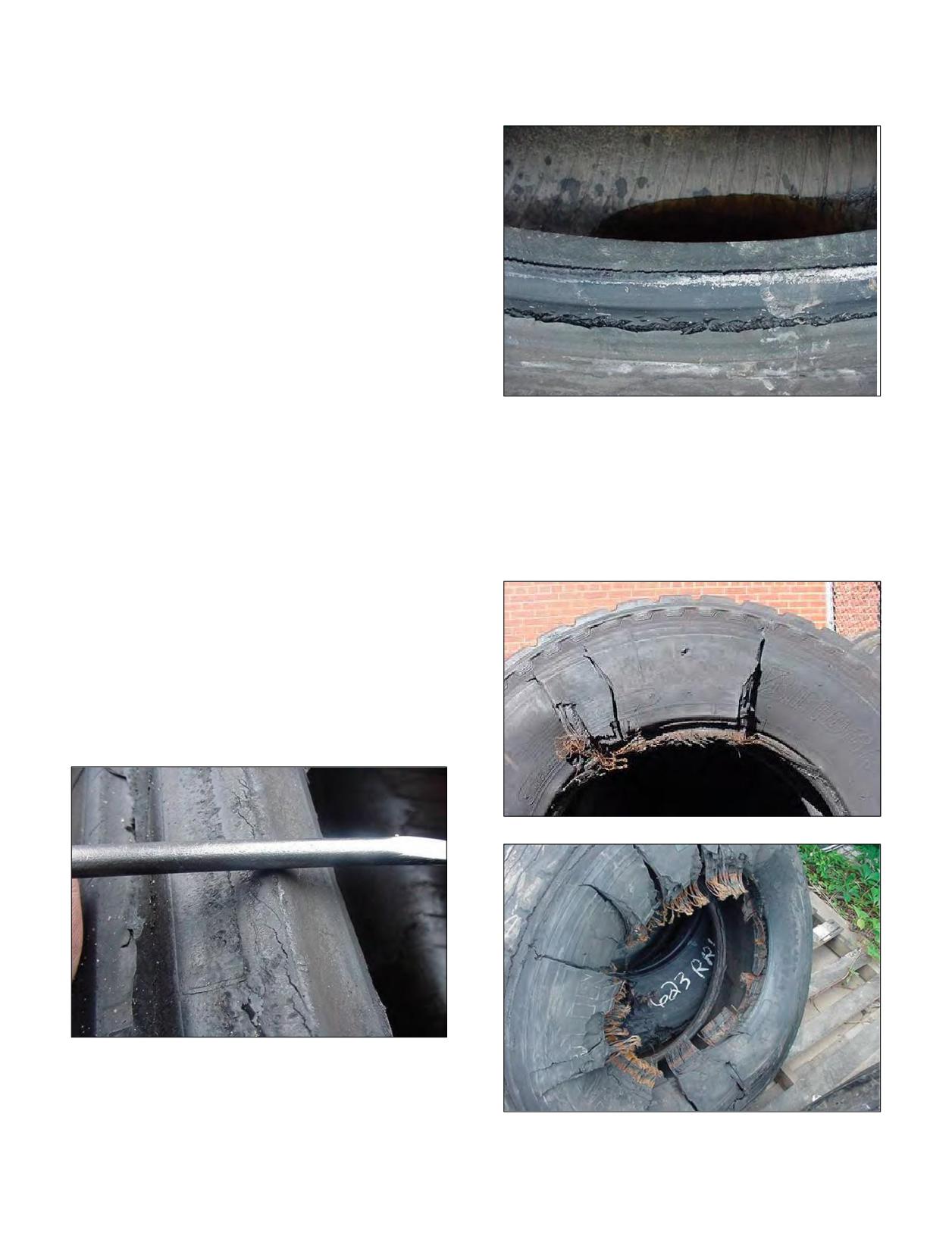
2nd Stage - Bead Splitting From Heat
2.Degradation of the casing: Heat is a tire’s worst
enemy! A tire subjected to high heat conditions over
The third stage is when the casing ply fully unwraps
an extended period of time will experience accelerated
from the bead. In extreme cases the casing ply unwraps
degradation of the rubber products. The degradation
from the bead all the way around the tire. At this point the
may result in a blowout during operation, or it may
tire completely separates from the bead wire. The bead
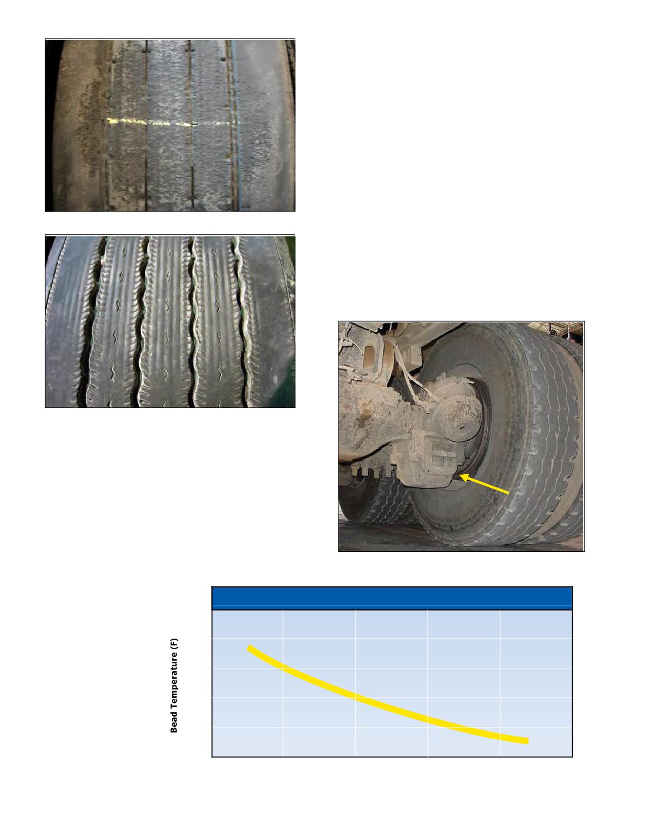
render the casing unsuitable for retread. The graph on
wire can entangle itself around the axle if this type
the previous page demonstrates how operating with
of separation occurs.
bead temperatures in excess of 200°F will significantly
reduce your casing life.
Bead damage as a result of brake heat is recognizable
in 3 stages of severity. In the first stage, the bead starts
to turn inward. This can be visibly identified on the tire
when it is dismounted. A straight edge placed across the
beads from one bead to the other no longer rests on the
bead point, but now rests closer to the bead bearing area.
3rd Stage - Partial Unwrapping of the Casing Ply
1st Stage - Turning of the Bead
3rd Stage - Complete Unwrapping of the Casing Ply
Section Four: Extending Tire Life
77
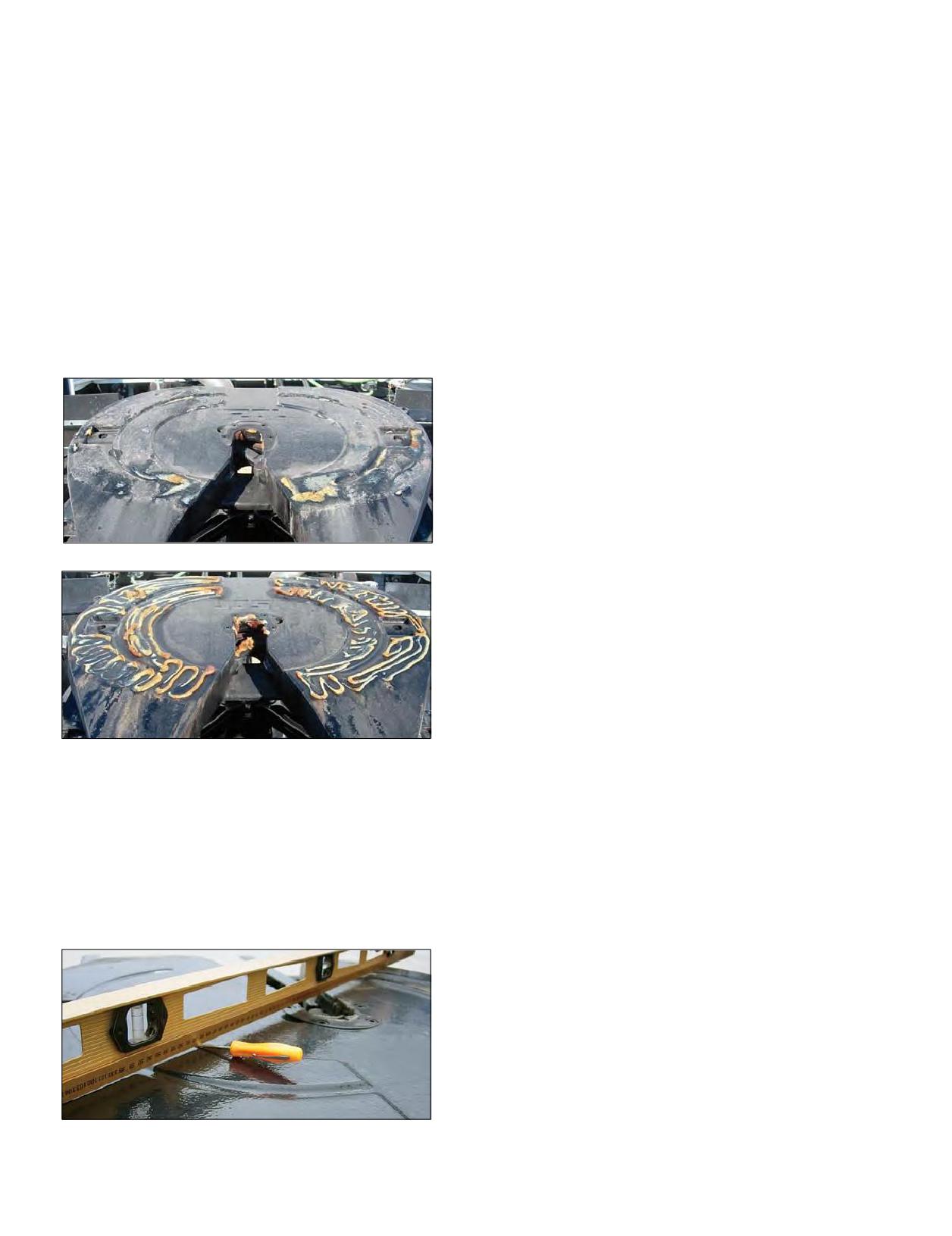
5TH WHEEL MAINTENANCE AND
WHEEL BEARING AND HUB INSPECTION
PLACEMENT
Driver pre-trip: Visually inspect each wheel end for
Placement of the 5th wheel can be determined by
loose, damaged or missing fasteners or hubcaps. Look for
the need to properly distribute the load over the drive
oil and lubricant leaks and oil level and condition.
tandems and the steer axle for legal loads. It can also be
Inspect in conjunction with preventative maintenance
placed to lengthen or shorten the overall length of the
schedule: With axle raised and supported, remove tire
tractor-trailer unit. However, with sliding 5th wheels, many
and wheel assembly, check for above items. Use a magnet
drivers place the 5th wheel to give the smoothest ride and
through the hubcab fill plug to detect any metallic materials
easiest steering. The placement and movement of the 5th
in the lubricant.
wheel can change the tire loading substantially, causing
12 month or 100,000 mile inspection: In addition to
tire overload or tire underload conditions. Insufficient
above items, check wheel end play (should be between
lubrication of the 5th wheel is a major cause of poor vehicle
0.001 and 0.005 inch). If at 0.000 or greater than 0.005 inch,
handling. Distortion of the 5th wheel plate will cause a
adjustment is necessary. Service accordingly following
similar condition to lack of lubrication and dog tracking of
manufacturer recommended procedures.
the trailer.
5 year or 500,000 mile service (frequency dependent on
service application): Follow manufactures recommended
procedures for removal/reassembly of hub assembly and
service of manually adjusted or pre-adjusted bearings and
Anti-Lock Braking System.
SUSPENSIONS
Forming the link between the truck and the tire, the
suspension system provides a very important contribution
to tire performance. The suspension must support the load
Insufficient Lubrication
and maintain the tire in the proper operating position on
the road. If the suspension is in good operating order, the
tires will track straight and be evenly loaded. This promotes
slow, even wear and low tire cost-per-mile.
Different truck manufacturers use different suspension
systems. Some of these are adjustable for making minor
changes, and some are not adjustable. All suspensions have
parts that move and are, therefore, subject to wear. Worn
or broken suspension parts are one of the main causes of
Proper Amount of Lubrication
irregular tire wear and handling concerns. (Ref. - Quick
checks for system and suspension faults on Pages 79-80.)
A 5th wheel in the most rearward position, combined
When observing irregular wear on a tire, first check for worn
with stiff front axle springs, can cause the front tire to
or broken front and rear suspension parts.
periodically unload, leading to vehicle shimmy and irregular
tire wear. Vehicle manufacturers usually recommend a 5th
AIR SUSPENSION SYSTEMS
wheel placement that results in payload transfer to the front
As vehicle manufacturers move away from multiple
axle. Improper front axle load distribution can adversely
springs, there is an increased need to dampen the effect
affect braking and handling, which can result in excessive
of road shock. Air suspension systems consist of fasteners
tire wear.
and bushings with various components such as air springs,
air or gas shocks, torque arms, air lines and valves held
together by nuts and bolts. Day to day operations generate
a constant twisting movement to all these parts and greater
awareness and maintenance diligence should be paid to
wear and proper torque to ensure proper performance of
the system and the effect this has on tire life. All torque
values should be verified to manufacturer’s specification,
and new shock absorbers should be considered when
installing new tires so as to maximize tire life. Shock
Distortion of the 5th Wheel
absorbers used on air ride suspensions should typically
78 Section Four: Extending Tire Life

provide effective dampening control for 150,000 miles
manufacturer instructions. Pivot Bushing inspection
of on-highway operations (100,000 miles for vocational
should consist of taking measurements before disassembly
applications). Refer to TMC RP 643, Air-Ride Suspension
to complete your inspection, complying with warranty*
Maintenance Guidelines on air suspension systems.
procedures, and replace the bushing if cracks or complete
Routine inspection of trailer air suspensions should
separation of the rubber is present.
be scheduled to inspect connectors and bushings per
* See warranty for details.
QUICK CHECKS FOR REAR SUSPENSION FAULTS
ISSUE
POSSIBLE CAUSE
• Improperly installed mounts and/or bushings
Shock Absorbers
• Damaged or leaking shocks
• Not torqued to specification
U-Bolts
• Improperly torqued due to mismatched metric and standard bolts with different specifications
• Loose attaching bolts
• Worn bushings in shocks, spring hangers, torque rods
• Missing alignment adjusting shims
Suspension System
• Excessive drive axle offset
• Excessive sway bar movement
• Worn hanger pins allowing axle movement
• Improperly functioning ride height control system
• Master or auxiliary spring-leaf broken
• Incorrectly installed springs
• Worn springs
Wheels out of Track
• Loose U-bolts
(Dog Tracking)
• Bent frame
• Torque rods improperly adjusted
• Torque rod bushings worn excessively
• Incorrect parallelism, skew, scrub
Alignment
• Dual position toe-in or out (induced toe value at each drive wheel)
• Camber
• Wheel bearings loose or damaged
Miscellaneous
• 5th wheel placement
• 5th wheel and chassis lubrication
QUICK CHECKS FOR TRAILER SYSTEM FAULTS
QUICK CHECKS WOULD INCLUDE:
• Verify OEM alignment after 1,000-3,000 in-service miles
• Alignment (induced toe value at each dual position,
• Verify rails are straight
negative camber, parallelism)
• Loose or missing fasteners, look for elongated holes
• Worn or loose wheel bearings
• Damaged or bent brackets
• Brake imbalance
• Look for wear at u-bolts and springs - signs of movement
• Slow release of trailer brake systems
• Look for signs of rust at track rod to indicate movement
• Operational conditions, high scrub application
• Inspect torque arm clamp nuts and bolts for proper torque
• Tire scrub/dragging at dock deliveries
(check threads to see if stripped)
(commonly called Dock Walk)
• Verify spring beams are centered on hanger; if not,
• Pressure maintenance (improper for operation)
check alignment
• Overloaded/underinflated, high speed empty hauls
• Slider assembly movement, loose attaching bolts,
• Mismatched pressure by dual position or axle
u-bolt torque
• Mismatched tread depth/tire design by dual position
• Air-ride suspension movement
• Improper tread depth for application/operation
• Insufficient lubrication
• New steer tire(s) mixed in trailer positions
• Worn shocks or springs
• Tire rotated from steer or drive with existing wear
• Bushings cracked or separated (inspect per manufacturer
• Improper tire assembly mounting
procedures)
• Driving habits, improper use of trailer brakes
Section Four: Extending Tire Life
79
QUICK CHECKS FOR FRONT SUSPENSION FAULTS
ISSUE
POSSIBLE CAUSE
• Loose or worn ball joints
• Loose front suspension attaching bolts
Thumps and Knocks from Front Suspension
• Missing adjusting shims
• Loose shock absorber mountings
• Check for worn or damaged spring eye bushings
• Loose attaching bolts
Groans or Creaks from Front Suspension
• Bent control arm or steering knuckle
• Worn kingpins or kingpin bushings
Squeaks from Front Suspension
• Coil spring rubbing on seat
• Worn tie rod ends
• Worn kingpins or kingpin bushings
• Loose suspension attaching bolts
Wander or Shimmy
• Weak shock absorbers
• Weak front springs
• Incorrect front end alignment
• Steering shaft U joint
• Weak front springs
Frequent Bottoming of Suspension on Bumps
• Weak shock absorbers
Front End Sag
• Weak front springs
• Incorrect front wheel alignment
• Worn kingpins or kingpin bushings
• Loose front suspension attaching bolts
• Weak shock absorbers
• Weak front springs
Irregular or Excessive Tire Wear
• Bent control arm or steering knuckle
• Worn tie rod ends
• Excessive steering system compliance
• Steering shaft U joint
• Loose wheel bearing
• Weak shock absorbers
Floating, Wallowing, and Poor Recovery from Bumps
• Weak front springs
• Worn kingpins or kingpin bushings
• Loose suspension attaching bolts
• Bent control arm or steering knuckle
Pulling to One Side While Braking
• Weak front springs
• Weak shock absorbers
• Loose wheel bearing
• Brake adjustment
• Damaged shock absorbers
• Weak shock absorbers
Rough Ride and Excessive Road Shock
• Weak springs
• Control arm shaft bushings need lubrication
• Worn kingpins or kingpin bushings
• Worn kingpins or kingpin bushings
• Loose suspension attaching bolts
• Worn control arm shaft bushings
Excessive Steering Play
• Weak front springs
• Worn tie rod ends
• Steering shaft U joint
• Loose wheel bearing
• Worn kingpins or kingpin bushings
• Loose suspension attaching bolts
• Worn control arm shaft bushings
Pulls To One Side
• Weak front springs
• Incorrect wheel or axle alignment
• Bent control arm or steering knuckle
• Worn kingpins or kingpin bushings
Hard Steering
• Incorrect front end alignment
• Bent control arm or steering knuckle
80 Section Four: Extending Tire Life
SECTION FIVE
MICHELIN
® X One® Tires
Section Five
MICHELIN® X One® Tires
81-112
DRIVER INFORMATION
82
AXLES AND WHEEL ENDS
83
Axle Identification Tags
Load Ratings
SPINDLES
86
OVERALL VEHICLE TRACK AND WIDTH
87
Use of Outset Wheels with MICHELIN® X One® Tires
Axles Track Widths
Vehicle Track
BEARINGS
89
ENGINE COMPUTERS / FUEL ECONOMY
90
AIR INFLATION AND PRESSURE MONITORING SYSTEMS
90
The Use of Pressure Monitoring and Inflation Systems
with MICHELIN® Truck Tires
Automated Tire Inflation Systems (ATIS) on Trailers
and Missed Nail Holes
TRUCK TYPE BY WEIGHT CLASS
92
Recommendation for use of MICHELIN® X One® Tires
in 4x2 Applications
TIRE PRESSURE MAINTENANCE PRACTICES
94
Comparative MICHELIN® X One® Tire Sizes Wheel
MICHELIN® X One® Tire Mounting Instructions
HEAT STUDY
96
Brake Heat Overview
Brake Heat Evaluation: MICHELIN® X One® Tires vs Duals
TIME LABOR STUDY - MICHELIN® X ONE® TIRES VS
DUAL ASSEMBLY
100-101
Torque
RETREAD AND REPAIR RECOMMENDATIONS
102-106
Repair Recommendations
Retread Recommendations
Chains
Gear Ratio
Footprint Comparisons to Dual Tire Fitments
OPERATION AND HANDLING
107-112
Over-Steer
Under-Steer
Cornering Stiffness for Different Tires
Hydroplaning
Rollover Threshold
Jack-Knife
Rapid Tire Pressure Loss Procedure
Traction
Chains
Stopping Distances
Limping Home
State and Local Regulations
Section Five: MICHELIN® X One® Tires
81
DRIVER INFORMATION
Pressure Maintenance
Drivers have commented that an under-inflated MICHELIN® X One® tire is more likely to be
detected with a simple visual inspection than dual tires. However, pressure is difficult to gauge
visually even for the most experienced driver.
s Do use a properly calibrated gauge when verifying
the pressure of a MICHELIN® X One® tire.
s Don’t rely on the appearance of the tire.
s Do remove and inspect any tire found to be 20% below
the recommended pressure.
Failure to do so may cause tire failure.
Vehicle Handling
Drivers have commented that the wide, stable footprint of the MICHELIN® X One® tire
can provide the feel of a much more stable truck compared to traditional dual tires.
However, while most MICHELIN® X One® tire fitments allow the track of the tractor and
trailer to be widened, the vehicle’s behavior in curves (on ramps or off ramps) is still subject
to roll-over at excessive speeds.
s Don’t let the outstanding handling of MICHELIN® X One®
tires give you a false sense of stability in curves.
s Do respect all posted speed limits regardless
of tire fitment.
Failure to do so may cause vehicle to tip.
Rapid Tire Pressure Loss Techniques
Extensive testing has shown that a rapid tire pressure loss on a MICHELIN® X One® tire will not
compromise the stability and behavior of the vehicle. However, with one tire on each axle end,
the loss of pressure will allow the wheel and axle end to drop and possibly contact the road
surface.
s Don’t try to “limp home” or continue to run on a flat tire.
Limping is a direct CSA (Comprehensive Safety Analysis) violation.
s Do down shift or use the trailer brake (when appropriate)
to avoid tire/wheel assembly lock-up.
s Do release the brakes intermittently as you slow down
to allow some rotation of the assembly.
Failure to do so may cause irreparable damage to the
tire, wheel, axle components, and vehicle.
82 Section Five: MICHELIN® X One® Tires
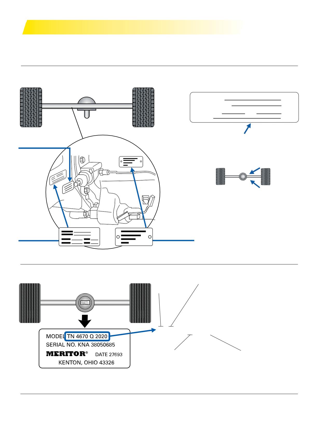
AXLES AND WHEEL ENDS
AXLE IDENTIFICATION TAGS
There are primarily three manufacturers of drive and trailer axles for the long haul highway market.
Meritor®, DANA, and Hendrickson all supply trailer axles, while only DANA and Meritor® supply drive axles.
Meritor® - DRIVE AXLE IDENTIFICATION
AXLE IDENTIFICATION TAG INFORMATION
Model No.
Customer No.
Serial No.
Plant
Ratio
Identification Tag
Axle Housing
Location of the identification tag, or stamp number,
Identification Tag
for the axles. Location is determined from the left
driver side looking toward the front of the vehicle.
A
B
A - Front engine drive - Right rear, next to cover
B - Rear engine drive - Left or right rear, next to
drive unit
Axle
Carrier
Identification Tag
Identification Tag
Meritor® - TRAILER AXLE IDENTIFICATION
Beam Type
Beam Capacity
T = Tubular
lbs
kg
N = 22,500
10,206
P = 22,500/25,000/30,000
10,206/11,340/13,608
Q = 25,000/30,000
11,340/13,608
R = 22,500/25,000
10,206/11,340
T N
4
6 7 0 Q
2 0 2 0
Modification
Brake Width
1 = Single Wheel
1 = 10” (25 cm)
2 = Intermodal
6 = 6” (15 cm)
3 = Bolted on Brakes
7 = 7” or 7.5” (18-19 cm)
4 = Manual Bearing Adjustment
9 = 8” (20 cm)
6 = Positive Bearing Adjustment
0 = No Brakes
8 = 0.625” Nominal Wall Axle
NOTE: The graphic provided is for reference only. Axle specific questions should be directed to the axle manufacturer.
Section Five: MICHELIN® X One® Tires
83
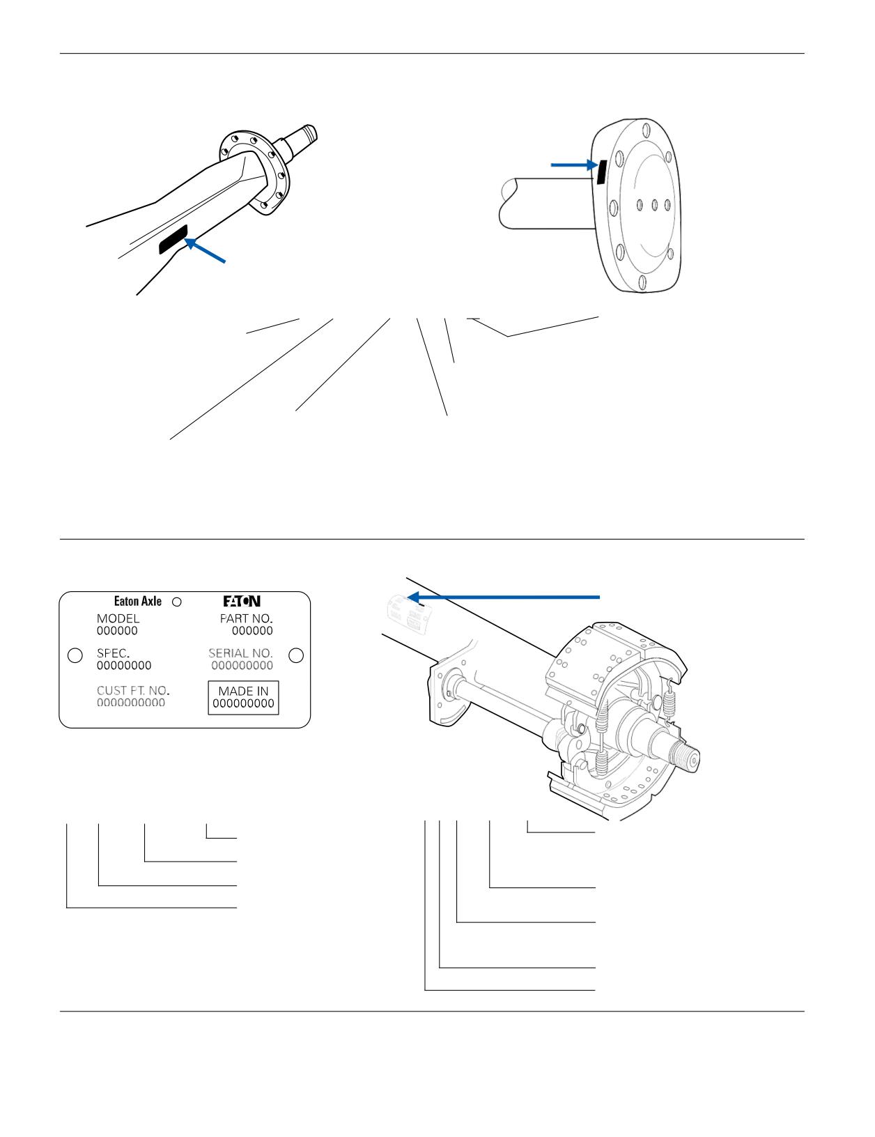
DANA - DRIVE AXLE IDENTIFICATION
Parts Identification
Axle Housing
Axle Shaft
1 - Axle Housing
2 - Axle Shaft Part Number
2
1
S 26 - 1 7 0 D
Options
D - Dual Drive Forward Axle
B - Bus/On-Center Bowl
with Inter-axle Differential
C - Controlled Traction
G - Single Rear Axle (Global)
D - Differential Lock
R - Dual Drive Rear Axle
Design Level
E - High Entry Single
S - Single Rear Axle (N.A.)
F - Flipped/Rolled Over
T - Tridem Configuration
H - Heavy Wall
Head Assembly Series
I - Integral Brake
Gear Type
L - Limited Slip
1 - Standard Single Reduction
GAW Rating
N - No Spin Differential
2 - Dual Range
X 1000 lbs. (N.A.)
O - Offset Change
5 - Helical Reduction
x 1 TN (Global)
P - Lube Pump
6 - Helical Overdrive
R - Retarder Ready
U - Unitized Spindle
W - Wide Track Housing
DANA - AXLE IDENTIFICATION
Identification Tag
0 00 000 0000
EST-225 J
Spindle Code
Serial Number
J - “J” Trailer Spindle
D - “D” Trailer Spindle
Julian Date
P - “P” Trailer Spindle
Year
Tube Capacity Rating
(x 100 lbs.)
Manufacturer’s Location
Brake Code
T - 16 1/2” x 7” Brake
R - 15” x 8 5/8” Brake
Extended Service Brake
Eaton
NOTE: The graphic provided is for reference only. Axle specific questions should be directed to the axle manufacturer.
84 Section Five: MICHELIN® X One® Tires
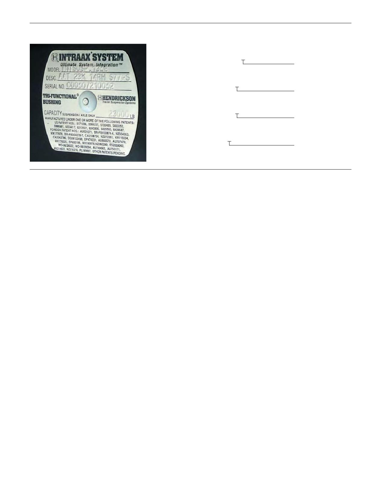
HENDRICKSON - TRAILER AXLE IDENTIFICATION
Model: VANTRAAX®.5836
Description: HKANT40K 165RH 77USHD MA X7SH
U - HUS Spindle
Model: VANTRAAX®.2157
Description: HKAT 50K 16RH 71NST QD X7SHD
N - N Spindle
Model: INTRAAX®.2597
Description: AAT 23K 14RH C77USST 7S
U - HUS Spindle
Model: INTRAAX®.3598
Description: AAL 30K 9RH 71PST
P - P Spindle
NOTE: The graphic provided is for reference only. Axle specific questions should be directed to the axle manufacturer.
LOAD RATINGS
Prior to contacting the axle manufacturer, you should
The load/capacity rating of a given axle is determined
consult the axle identification tag to obtain the following
by the axle housing strength, bearing capacity, and hub
information:
- Axle Manufacturer
capacity. For some ultra-lightweight axles, the reduced
axle housing thickness may be the weak link, but usually
- Manufacturer’s Model #
it is the bearings or hub that will be the limiting factor.
- Axle Serial Number
- Axle Capacity
These axles and components are typically designed
undertheassumptionthattheactionline of the tire load
Information on actual operational axle loading
(as opposed to rated load) is crucial, since the axle
is located between the two bearings. This is typically
manufacturer may recommend de-rating the axle below
found with dual tire mounting or with single tires with
very low outset wheels with the axle rating being similarly
the vehicle manufacturer’s GAWR (Gross Axle Weight
determined.
Rating).
With this data in hand, contact the particular axle
If wheels with greater outset are used, the resulting
cantilever loading may require lower ratings for some
manufacturer at the numbers listed below for specific
application information.
of the axle components. The level of de-rating and
the implications thereof are determined by the axle
manufacturer, so they should be consulted prior to
DANA - www.dana.com
fitment of outset single wheels.
Hendrickson - www.hendrickson-intl.com
Section Five: MICHELIN® X One® Tires
85
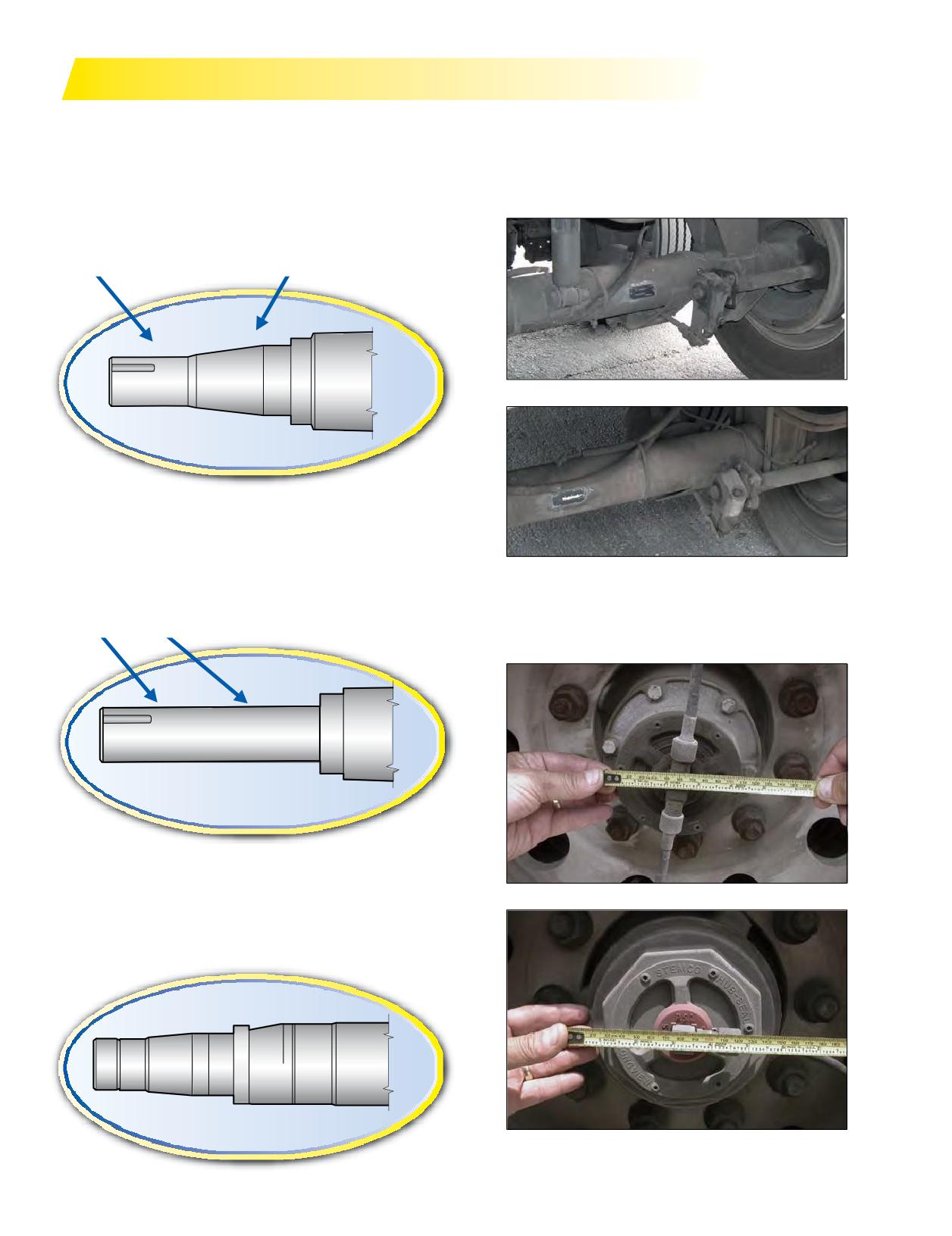
SPINDLES
There are three main spindle types you will encounter
The best way to determine what type of spindle may be
when retrofi
MICHELIN® X One® tires: “N”, “P”, and “R”.
fitted to a given axle is to reference the axle ID data plate
affixed to the axle or the suspension ID tag as described
N-TYPE SPINDLES (TAPERED)
on Pages 83-85. The following photos display actual tag
N-type spindles are tapered to the outboard end and
placements.
utilize a smaller outboard bearing and a larger inboard
bearing.
Outer bearing smaller than inner bearing.
Tag Placement
P-TYPE SPINDLES (STRAIGHT)
P-type is a parallel spindle design (straight shaft) and
utilizes the same sized bearings inboard and outboard.
Tag Placement
This is generally a heavier duty axle end.
Outer and inner bearings the same size.
A quick rule of thumb is to measure the hub cap.
N-type is usually ~4.5” and the P-type is usually ~6.0”.
R-TYPE SPINDLES
R-type is a drive axle spindle configuration. The R-type
N-Type Spindle
spindle for drive axles is typically straight with bearings of
nearly the same size.
P-Type Spindle
86 Section Five: MICHELIN® X One® Tires
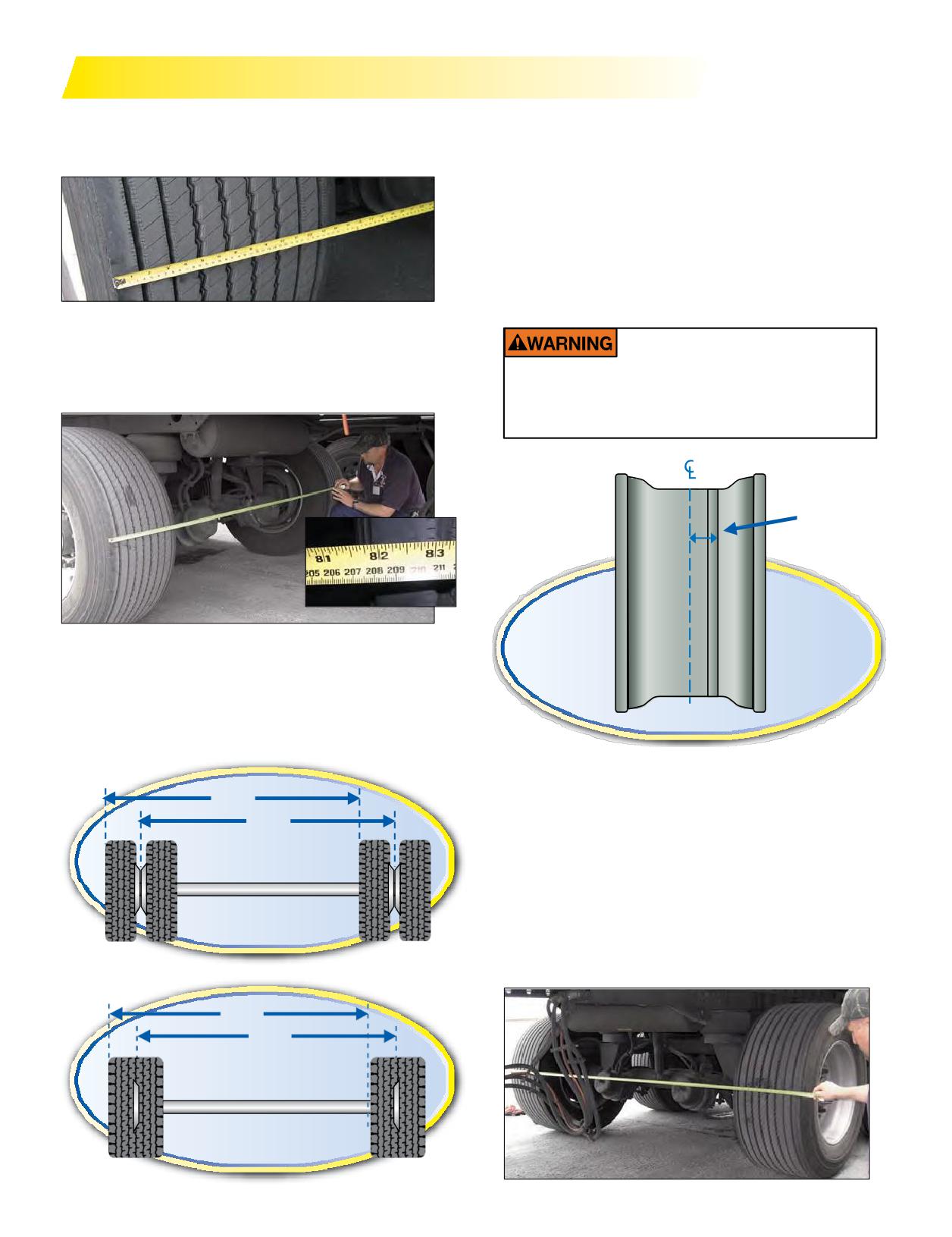
OVERALL VEHICLE TRACK AND WIDTH
Vehicle track width is determinedbytakingthe axle
This method also works well for determining the track
track width and adding or subtracting the left and right
width on dual tires.
wheel outsets or insets respectively.
Without changing the width of your axle, your track width
can change depending on your wheel outset or inset.
Outset: The lateral distance from the wheel centerline to
the mounting surface of the disc.
Outset places the wheel centerline outboard of the
mounting (hub face) surface.
Inset places the wheel centerline inboard of the mounting
(hubface) surface or over the axle.
Aneasywaytomeasurethisyourselfis to start on the
left side of the axle, hooking your tape on the outside
edge of the tread. Stretch the tape to the right side of the
If 2” outset wheels are mounted backwards,
axle andmeasureto the inside edge of the tread.
this will significantly reduce track width and
could affect vehicle stability possibly leading
to an accident, injury or death.
Disc Face
Outboard
Inboard
Take the measurement where the tape measure crosses
the left edge of the right side tire’s tread.
The measurement you have just taken is your vehicle’s
track width. Simply put, it is the center to center distance
OUTSET
of your tires.
Overall width of axle assembly is determined by
77.5"
measuring the outer tire sidewall to outer tire sidewall. This
77.5"
measurement is takenat the top of the tire’s sidewall to
avoid measuring the sidewall deflection. The Federal DOT
(Department of Transportation) maximum allowed is 102
For a close approximation, clip the end of the tape
measure on the left tire’s outside sidewall and pull the tape
to the outer sidewall of the outer tire on the opposite side.
Dual Tires
Ifyourmeasurementis close to 102”, then amore precise
method will be required.
80.5"
80.5"
MICHELIN® X One® Tires
Section Five: MICHELIN® X One® Tires
87
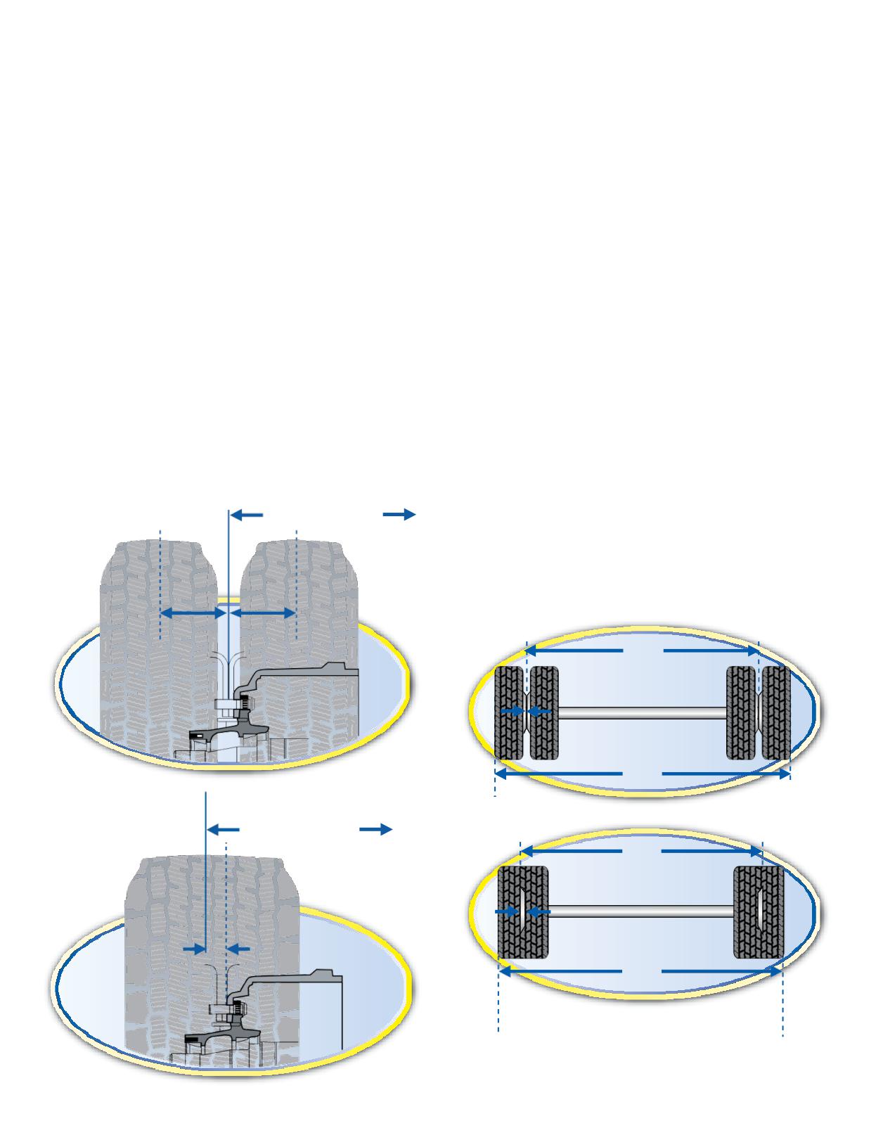
USE OF OUTSET WHEELS WITH
AXLES TRACK WIDTHS
MICHELIN® X ONE® TIRES
Three standard trailer axle track widths are available.
The MICHELIN® X One® tires (445/50R22.5 and
They are 71.5”, 77.5”, and 83.5”. A typical tandem drive
455/55R22.5)require the use of 14.00 x 22.5” wheels.
axle track width is approximately 72”. Check with the axle
Themajority view of the wheels currently offered today
manufacturers for other sized options.
have a 2” outset.
Some axle and hub manufacturers have clarified and
Axle width is measured from spindle end to spindle end
confirmed their position concerning the use of such wheels
(the two widest points).
with their respective components. While the position of
Axle track is a center to center distance between the dual
the component manufacturers is not totally consistent,
or center of single tire to center of single tire.
the majority view of the wheel currently offered have a 2”
outset.
71.5” is a standard axle track width found on bulk and
Truck and trailer manufacturers may have different
liquid tankers.
specifications. For optimum track width, stability, and
77.5” is a standard axle track width for 102” wide trailers.
payload, end-users should talk to their trailer suppliers
83.5” is the newer wider track axle intended for use with
about the use of 83.5” axles with zero outset wheels.
wide singles and 0” outset wheels for increased track width,
A trailer specified with 83.5” inch axles is intended for
stability, and payload.
single tire use. Switching to dual tire configuration could
exceed the legal maximum overall width of 102”.
VEHICLE TRACK
End-users that have retrofitted vehicles with 2” outset
With a standard length axle and 2” outset wheels,
wheels should contact their respective vehicle, axle,
the resulting variation in track width is an increase of
or component manufacturers for specific application
approximately1.5”per side(3” total) as compared to
approvals or maintenance recommendations.
a dual tire configuration.
End-users that have retrofi
vehicles with 2” outset
Actual Track Width
wheels should contact their respective vehicle, axle,
or component manufacturers for specific application
approvals or maintenance recommendations.
Measurements are rounded.
Duals
Wheel
Wheel
Outset
Inset
77.5"
Track Width
0" Outset
101.5"
X One Tires
Actual Track Width
80.5"
Track Width
2" Outset
Wheel
Outset
97.9"
Note: Measurements are nominal values
and could vary with manufacturer.
88 Section Five: MICHELIN® X One® Tires
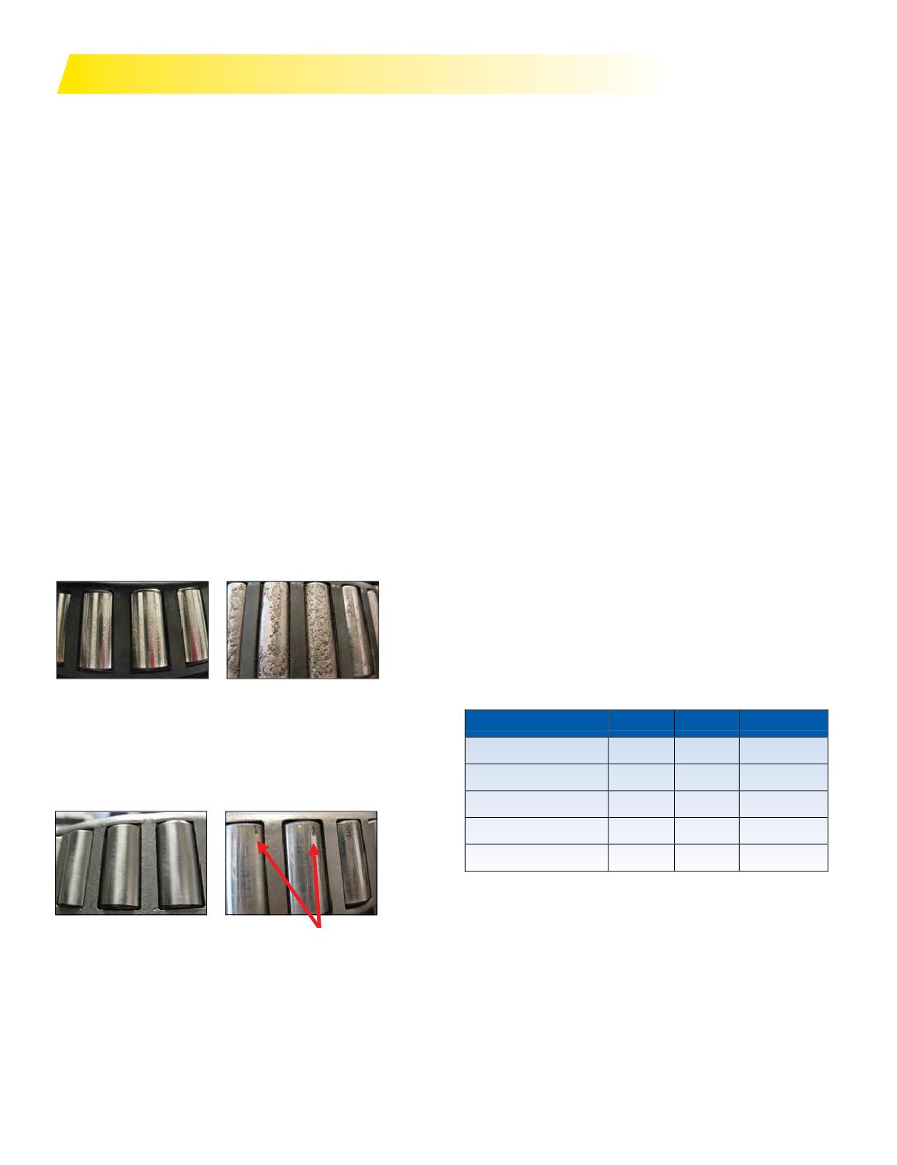
BEARINGS
Wheel-end bearings for trucks and trailers are typically
TMCrecommendsall axle ends be checked annually or at
the tapered roller type with either grease, semi-fluid grease,
100,000 miles. For more information, refer to TMC RP631A,
or oil level lubrication. Anticipatedbearinglifeis compared
Recommendations for Wheel End Lubrication.
by running an ANSI (American National Standards Institute)
Usingstandardbearings witha 2” wheel outseton a N-type
L10a test to statistically determine the fatigue life. The test
spindle arrangement does reduce the L10a bearing life
variablesare wheel endloading(amountandlocation),
expectancy. Bearing manufacturers offer enhanced bearings
bearing end-play, tire and wheel weight, tire static loaded
for trailer and drive axle applications that provide L10a
radius, and duty cycle (vehicle speed and turn frequency
lifewith2”outset single wheels near thatof conventional
and lateral g loading). The output is L10a Weighted Bearing
bearings with dual wheels.
System Life in miles.
These bearings have an extra roller with a slightly
The common belief among fleet maintenance technicians
different contact geometry between the cup and cone and
is that bearings do not fail or wear out in normal service
are machined to tighter tolerances and a smoother surface
unless subjected to loss of lubricant, excessive endplay, or
finish.
excessive preload.
Timken’s 454-Series™ wheel bearings*:
However, due to increased variances in the quality
• One bearing for Dual and Wide Singles
of bearings in the market place, proper inspection/
- Specially designed to handle the 2” outset loads
maintenance practices should be employed to ensure
- Allows consistency within fleet
preventing premature failures and extending the life of the
- Provides flexibility of wheel arrangements
bearing.
• Compatible with industry standard components
- Use with popular axle and hub designs
Poor Quality Bearings
- Can retrofit onto existing equipment
• New bearings show pitting on the rollers
• Bearing failure mode is spalling across the entire roller
*For more information on the Timken® 454-Series™ wheel
• Bearing cage failures also occurs
bearings, visit The Timken Company at www.timken.com.
IMPORTANT: Somewheelbearingassemblieshave
warranties that may be voided when the wheel ends
are disassembled. Contact your axle and/or suspension
component supplier before removing any wheel end
components.
“New” Bearings
Old Bearings
Cone
Cup
MileMate® Set*
Good Quality Bearings
• New bearings show a perfect clean finish
N Trailer Outer
NP454049
NP454011
Set 440
• Bearings fail in an expected failure mode; light spalling on
N Trailer Inner
NP454248
NP454210
Set 441
the loaded edge
R Drive Outer
NP454580
NP454572
Set 442
R Drive Inner
NP454594
NP454592
Set 443
P Trailer Inner & Outer
NP454445
NP454410
Set 444
*454-Series™ is a trademark of The Timken Company. Timken® and MileMate® are
the registered trademarks of The Timken Company.
See www.timken.com/454wheelbearing for Limited Warranty information.
New Bearings
Old Bearings
Section Five: MICHELIN® X One® Tires
89
ENGINE COMPUTERS / FUEL ECONOMY
Tire revolutions and axle ratio are inputs to the Engine
switching to MICHELIN® X One® tires, it is recommended that
Control Module (ECM) to manage road speed. Changing
SAE (Society of Automotive Engineers) J1321 (revision) -
from dual to MICHELIN® X One® tiresmay require changing
Type II Fuel Test be conducted to verify the values
the Tire Revolutions per Mile (Tire Revs./Mile) value in the
determined by the engine computer.
ECM in order to ensure speed, distance, and fuel economy
New EGR (Exhaust Gas Recirculation) engines may use
are accurate per indications. Reference the MICHELIN®
diesel fuel to clean the DPF (Diesel Particulate Filter). When
Truck Tire Data Book (MWL40731) for proper Tire Revs./
checking fuel usage please be aware of the additional fuel
Mile values for the MICHELIN® X One® tires you chose.
used during regeneration of the DPF.
To accurately determine fuel efficiency gains from
AIR INFLATION AND PRESSURE MONITORING SYSTEMS
Proper inflation pressure is critical to the overall
recommended for that tire. A flat tire must be removed from
performanceofall tires on the road today.
the wheel, thoroughly examined, and properly repaired
Today’s radial truck tires will loseless than one psi per
prior to re-inflation and use.
month due to air migration through the casing. Faster loss
Some systems provide inflation pressure information
of inflation can only occur in conjunction with some sort
at the sensor site only, so the driver must walk around the
of leak in the wheel, valve stem, or tire structure. Whatever
vehicle to gather/view either the pressure reading or low
the source of the leak, it must be identified and corrected to
pressure warning. Other systems transmit the information
avoid further damage to that component, possibly leading
to the cab where it may be viewed by the driver, and/or sent
to a compromiseinsafety.
to a central facility if the vehicle is tracked by satellite.
AVAILABLE SYSTEMS
Tire Pressure Monitoring Systems (TPMS) have been
Automated Tire Inflation Systems (ATIS) are
not guarantees against low pressure situations.
legislated for all vehicles by the TREAD Act (Transportation
All vehicles should still be subject to pre-trip
Recall Enhancement, Accountability, and Documentation).
inspections, and systems operation should be
The implementation schedule is in place for vehicles with
verified routinely.
gross vehicle weight (GVW) below 10,000lbs, butis yet to be
determined for heavier vehicles. The existing systems
“read” the pressure in the tire via a sensormounted on the
Automated Tire Inflation Systems (ATIS)
valve stem, wheel, or inside the tire. Sensors that are not
are designed to addair tomaintain a preset pressure but do
physically inside the tire and wheel cavity cannot accurately
not havetheability to reduce the pressure should a tire be
measure the internal air temperature, so they are unable to
over inflated. These systems can account for slower leaks
determine the “cold inflation pressure.” In addition, external
(determined bytheair delivery capacity of the system)
sensors may require additional inflation line plumbing that
andprovidesomewarningto thedriverwhenthesystem
creates additional potential leak points.
is energized (adding air) or when it cannot keep up with
Monitoring systems may provide either pressure data or
the leak. Almost all inflation-only systems use air from the
alowpressure warning.Thepressuredatamaybe“hot”or
vehicle air brake system, so they will belimited inmax
“cold” pressure, so it is necessary that the person viewing
pressure and available volumetric flow. In addition, these
that data fully understands which pressure is reported
systems are usually only applied to trailer axles where
and what it means. Low pressure alarm systems only alert
plumbing the air supply line is easier.
the driver when the pressure in a particular tire (or pair of
Even with the inflation system in place, routine manual
dual tires if linked together) is below some fleet-chosen
inflation pressure checks are still required.
minimum. This value may be preset by the sensor supplier
Tire inflation systems may add air to tires determined to
or may be programmable by the fleet. Tire manufacturers,
bebelowsomefleet chosenpressure. SomeAutomatedTire
through the U.S. Tire Manufacturers Association (USTMA),
Inflation Systems (ATIS) will also allow pressure reduction
haveagreed that a tiremust be considered flat if the
onany tire on the vehicle tomaintain some given pressure
inflation pressure is 20% or more below the pressure
level. Such systems are rather expensive and more often
90 Section Five: MICHELIN® X One® Tires
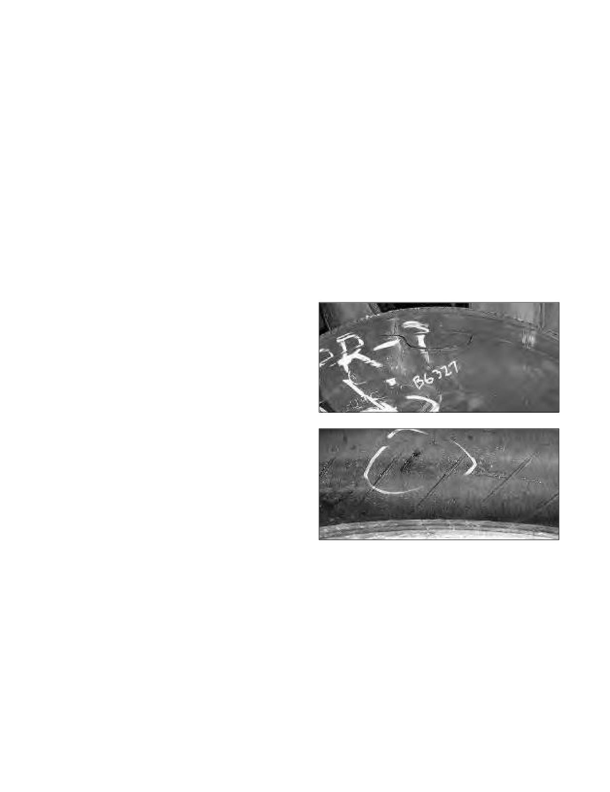
used only on specialty vehicles (Military, emergency
AUTOMATED TIRE INFLATION SYSTEMS
response, National parks, etc.).
(ATIS) ON TRAILERS AND MISSED NAIL
Akeyfactor in anymonitoring orinflation system is
HOLES
determining whether the target or set pressure is a “hot”
Automated Tire Inflation Systems (ATIS) on trailers can
pressure or a “cold” one. This should be discussed with
sometimes make slow leaks caused by nails or other small
your tire manufacturer’s representative.
objects penetrating the crown area of the tire undetectable.
A slow leak can be compensated for by the air inflation
THE USE OF PRESSURE MONITORING
system. The warning light of the ATIS system will only
AND INFLATION SYSTEMS WITH MICHELIN®
come on if the pressure in the tire drops below a certain
TRUCK TIRES
percent (usually 10%) of the regulated preset pressure. Even
whenthe pressure drops belowthis point, the light will go
In view of the increasing visibility and promotion for
off if the system is able to restore andmaintain the preset
the use of pressure monitoring and/or inflation systems,
pressure.
Michelin takes the following position:
The tires on trailers with ATIS systems should be visually
• Michelin has not and cannot test every system that
inspected before and after use and any imbedded objects
is being marketed/manufactured for effectiveness,
removed and the tire repaired. An undetected imbedded
performance, and durability.
object remaining in the tire can allow air infiltration and
• The use of these systems does not nullify the MICHELIN®
consequently a possible catastrophic failure of the sidewall.
truck tire warranty unless it is determined that the
system somehow contributed to the failure or reduced
performance of the tire.
• Proper pressure maintenance is important for the optimal
performance of the tires, so it is important tomake sure
the system can maintain the pressures needed and/or can
detect accurately when the pressures are outside of the
normal operating range(s) for the loads being carried.
• It is the responsibility of the system manufacturer to
ensure that the tires are inflated as rapidly as possible
to the optimal operating pressure in order to prevent
internal damage to the tires.
• Michelin strongly urges the customer to put the
responsibility on the system’s manufacturer to prove and
support their claims.
In addition to the foregoing, please refer to the
MICHELIN® Truck Tire Warranty Manual (MWE40021) for
a general discussion of what is and is not covered by the
warranty.
Section Five: MICHELIN® X One® Tires
91
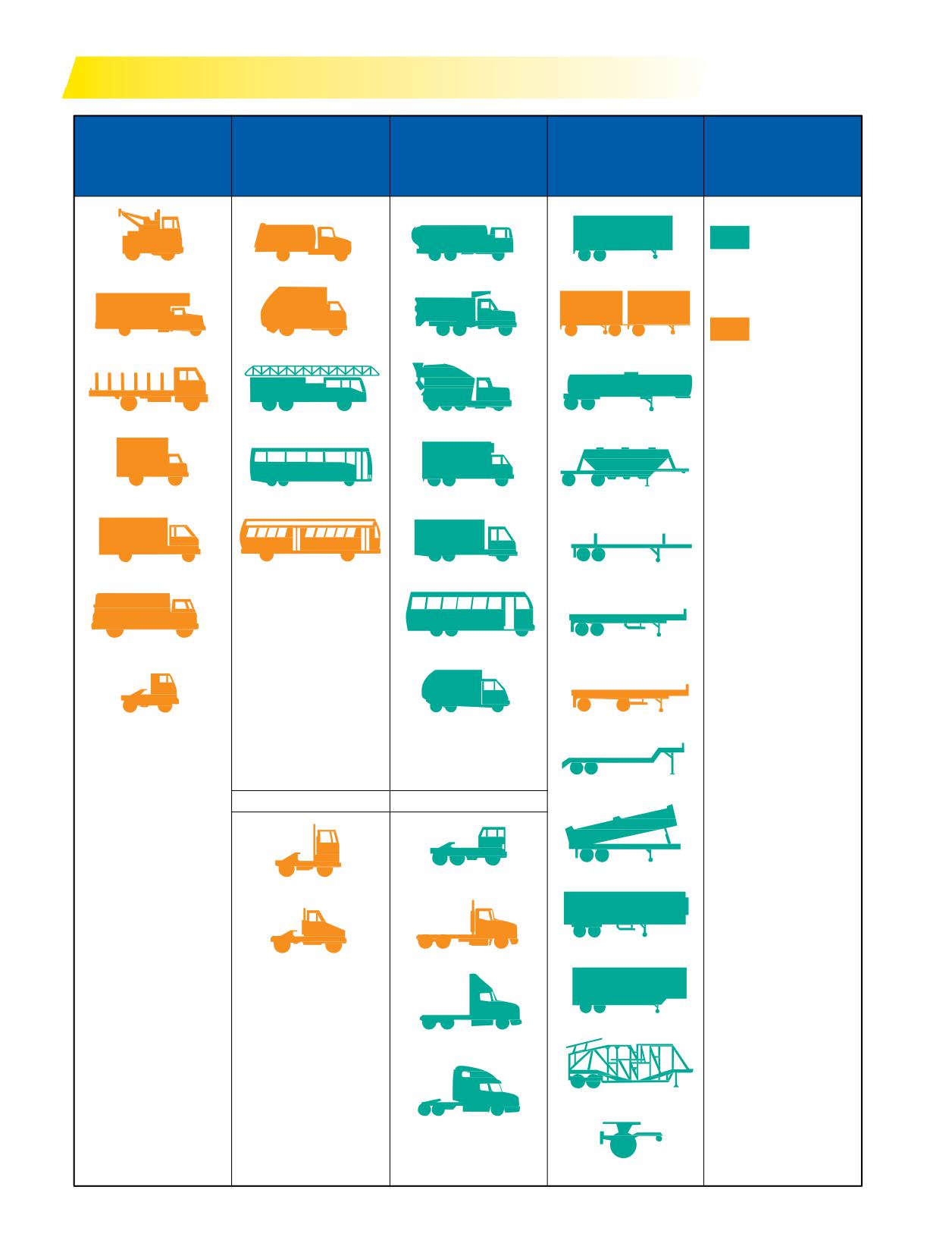
TRUCK TYPE BY WEIGHT CLASS FOR USE WITH X ONE® TIRES
CLASS 6
CLASS 7
CLASS 8
TRAILER
NOTES
19,501 to 26,000 lbs.
26,001 to 33,000 lbs.
33,001 lbs. and over
Weight: Not specified
GVW
GVW
Recommended
Applications
TOW
HOME FUEL
FUEL
DRY VAN
Contact
Michelin
FURNITURE
TRASH
DUMP
DOUBLES
For information
on the MICHELIN®
XOne® tire for the 4x2
STAKE
FIRE ENGINE
CEMENT
LIQUID TANK
application, refer to the
next page.
GVW - Gross Vehicle
COE VAN
SIGHTSEEING/COACH
REEFER
DRYBULK
Weight
The total weight of the
loaded vehicle includes
chassis, body, and
payload.
SINGLE AXLE VAN
TRANSIT BUS
TANDEM AXLE VAN
LOGGER
GCW - Gross
Combination Weight
Total weight of
loaded tractor-trailer
BOTTLER
INTERCITY BUS
PLATFORM
combination includes
tractor-trailer and
payloads.
GAWR - Gross Axle
LOW PROFILE COE
TANDEM REFUSE
SPREAD AXLE
Weight Rating
Maximum allowable
load weight for a
specific spindle, axle,
DROP FRAME
and wheel combination.
GCW TO 65,000
GCW TO 80,000
Identical vehicles may
appear in different
vehicle weight classes.
LOW PROFILE
DUMP
This is because of
HIGH PROFILE COE
TANDEM COE
a difference in the
components installed
in each vehicle such as
engines, transmissions,
REEFER
rear axles, and even
MEDIUM
HEAVY CONVENTIONAL
tires that are not readily
CONVENTIONAL
discernible in the
external appearance
of those particular
DEEP DROP
vehicles.
HEAVY TANDEM
CONVENTIONAL
AUTO TRANSPORTER
HEAVY TANDEM
CONVENTIONAL
SLEEPER
DOLLY
92 Section Five: MICHELIN® X One® Tires
RECOMMENDATION FOR USE OF MICHELIN® X ONE® TIRES IN 4x2 APPLICATIONS
4x2 Articulated Vehicles
Michelin still maintains that all types of motor vehicles
Handling studies have indicated that for certain
can be controlled in the event of a rapid tire pressure loss
types of commercial single axle (4x2) tractors pulling
under normal, legal driving conditions. Vehicle control
trailers, handlingmay be degradedin the event of a
in a rapid tire pressure loss situation is a matter of driver
rapid tire pressure loss when fitted with single tires.
education and training. To assist with this training,
Michelin recommends that single axle tractors fitted with
Michelin has produced a video entitled “Rapid Air Loss,
MICHELIN® XOne® tires on the driven axle always be
Truck-TheCritical Factor” toinstruct drivers on how to
equipped with an Electronic Stability Program (ESP).
handle a rapid tire pressure loss situation.
To view the video - “Rapid Air Loss, Truck - The Critical
Factor” - please visit our web page at www.michelintruck.
4x2 Straight Chassis Vehicles
com/reference-materials/videos/#/maintenance-and-
Testing has indicated that handling of 4x2 straight
training. For additional information, please contact your
chassis vehicles fitted with single tires on the drive axle
local Michelin sales representative, or contact Michelin
maybedegraded in the event of a rapid tire pressure loss,
using the website www.michelintruck.com.
especially when coupled with panic braking. Class 6 and 7
straight trucks fitted with MICHELIN® X One® tires should
also be equipped with anti-lock brake system (ABS) and/or
ESP. Such degradation in handling has been observed both
in curve, lane change, and straight line driving.
Section Five: MICHELIN® X One® Tires
93

TIRE PRESSURE MAINTENANCE PRACTICES
Below is tire pressure maintenance advice for users of the
on a vehicle carrying 17,480 lbs. per axle, the appropriate
MICHELIN® X One® wide single truck tires (445/50R22.5
pressure is 100 psi (cold).
LRL and 455/55R22.5 LRL).
For trailers equipped with a pressure monitoring
Proper pressure maintenance is critical to obtain
system, system pressure should be regulated based on
optimized performance from these tires. Due to the unique
the maximum load the axle will carry and be at the cold
casing design of theMICHELIN® X One® tire, traditional
equivalent for this load.
pressure adjustment practices for dual tires may not apply
When an aluminum wheel is used in the outset position,
to MICHELIN® X One® tires.
the new TR553E valve should be used. It is recommended
Cold inflation pressure should be based on maximum
that you verify air valve stem torque on all wheels put into
axle load in daily operation. Cold inflation pressures must
service. When installed, they should have correct torque,
not be lower than indicated in the tables below for actual
using the proper tool at 80 to 125 in./lbs.(7 to 11 ft./lbs.) for
axle loads. For additional information, please consult the
aluminum wheels and 35 to 55 in./lbs. (3 to 5 ft./lbs.) for steel
MICHELIN® Truck Tire Data Book (MWL40731).
wheels. To checkfor slow leaks at the valve stem, use either a
For example, load range L (20 ply) tires like the
torque wrench byhand orspray asoapy solutionon the valve
445/50R22.5 MICHELIN® X ONE® LINE™ ENERGY D tires
to see if it is loose. To prevent galvanic corrosion on aluminum
haveamaximumpressureof120psi(cold) withaweight
wheels, lubricate the threads and o-ring of the valve stem with
carrying capacity of 20,400 lbs. per axle. If the tire is mounted
a non-waterbased lubricant before installation.
Wheel Diameter
PSI
75
80
85
90
95
100
105
110
115
120
125
130
MAXIMUM LOAD AND
PRESSURE ON SIDEWALL
22.5”
kPa
520
550
590
620
660
690
720
760
790
830
860
900
445/50R22.5 LRL
LBS SINGLE
13880
14620
15360
16060
16780
17480
18180
18740
19560
20400
S
10200 LBS at 120 PSI
X ONE LINE ENERGY D
X ONE LINE ENERGY T
X ONE MULTI ENERGY T
KGSINGLE
6300
6640
6960
7280
7620
7940
8240
8500
8860
9250
S
4625 KG at 830 kPa
X ONE XDN2
LBS SINGLE
15000
15800
16580
17360
18120
18880
19640
20400
21200
22000
S
11000 LBS at 120 PSI
455/55R22.5 LRL
X ONE XDN2
X ONE MULTI ENERGY T
KGSINGLE
6800
7160
7520
7880
8220
8560
8900
9250
9580
10000
S
5000 KG at 830 kPa
LBS SINGLE
16580
17360
18120
18880
19640
20400
21200
22000
22600
23400
S
11700 LBS at 130 PSI
455/55R22.5 LRM
X ONE XZU S
X ONE XZY3
KGSINGLE
7520
7880
8220
8560
8900
9250
9580
10000
10240
10600
S
5300 KG at 900 kPa
* Single configuration, or 2 tires per axle.
94 Section Five: MICHELIN® X One® Tires
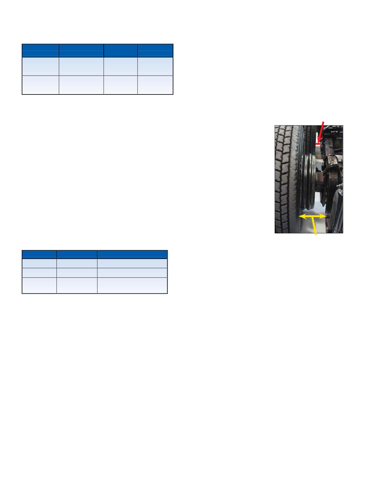
COMPARATIVE MICHELIN® X ONE® TIRE
MICHELIN® X ONE® TIRE MOUNTING
SIZESWHEELS
INSTRUCTIONS
The MICHELIN® X One® tire must be mounted on
MICHELIN®
MICHELIN® X One®
Dual
Dual Size
22.5 x 14.00” size wheels. Both steel and aluminum are
X One® Tire Size
Tire Revs./Mile
Tire Revs./Mile
available in Hub (Uni Mount) piloted, and currently
515
511
445/50R22.5
275/80R22.5
aluminum is available in Stud (Ball Seat) configuration.
(X One® XDN®2)
(XDN®2)
Supplemental parts will be required with ‘Stud-Piloted’
492
11R22.5 or
495
wheels; i.e. front and rear outer cap nuts to replace inner
455/55R22.5
(X One® XDN®2)
275/80R24.5
(XDN®2)
and outer nuts used for mounting traditional stud-piloted
dual assembly. Wheel specific questions should be directed
The MICHELIN® X One® tire requires the use of
to the wheel manufacturer. To ensure proper stud length,
22.5 x 14.00” wheels. Both steel and aluminum wheels
there should be 4 threads
Incorrect Lateral Clearance
are currently available in 0”, 0.56”, 1” and 2” outsets. The
visible from the nut. There
majority of the wheels currently offered have a 2” outset.
are nodifferencesinmount
Outset: The lateral distance from the wheel centerline to
or dismount procedures
the mounting surface of the disc. Outset places the wheel
other than when mounting
centerline outboard of the mounting (hub face) surface.
the MICHELIN® X One® tire
Inset places the wheel centerline inboard of the mounting
ontoavehicle, position the
(hub face) surface or over the axle. Thus a wheel with a 2”
tire so that the tire sits on
outset has the centerline of the wheel base 2” outboard from
the outbound side of the
the hub mounting surface.
wheel similar to where the
Some axle and hub manufacturers have recently clarified
outer dual would normally be
and confirmed their position concerning the use of such
positioned. Additionally, this
wheels with their respective components. While the position
will offer exceptional lateral
of the component manufacturers is not totally consistent,
clearance. Select a valve
the majority’s view concerning the retrofit of duals with
stem that can be accessed
MICHELIN® XOne® tirescan besummarizedas follows:
for pressure checks and is
Correct Lateral Clearance
installed facing outward.
Axle Type*
Spindle Type
Wheel Recommendation
Drive axles
“R”
0” to 2” outset wheels**
NOTE: Safety cages, portable and/or permanent, are also
Trailer axles
“P”
2” outset wheels
available and required forinflation of theMICHELIN®
Check with component
X One® tire assemblies.
Trailer axles
“N”
manufacturer.
* Many other axle and spindle combinations exist. Contact axle manufacturer.
** Contact axle manufacturer before retrofitting 2” outset wheels.
NOTE: Use of outset wheels may change Gross Axle
Weight Rating (GAWR). Consult vehicle and component
manufacturers.
Section Five: MICHELIN® X One® Tires
95
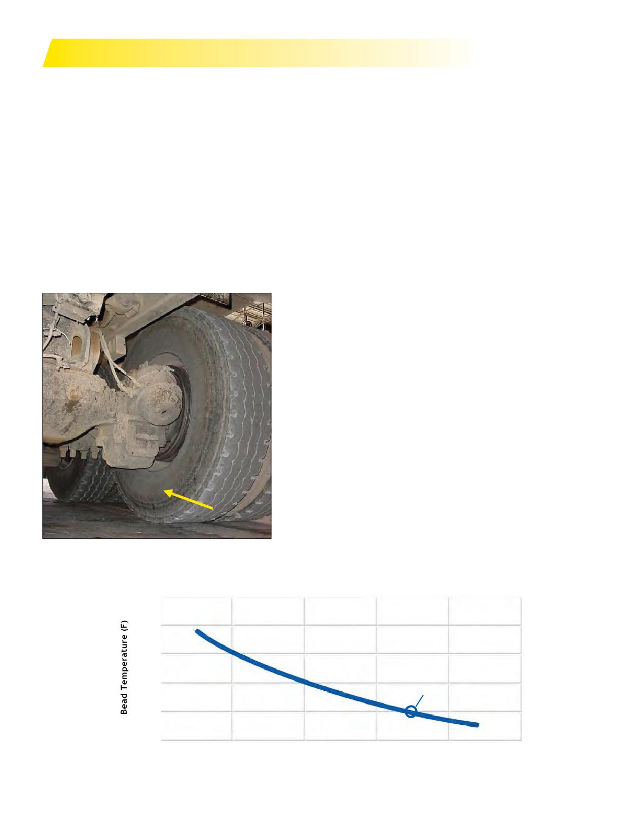
HEAT STUDY
BRAKE HEAT OVERVIEW
Excessive bead heat can affect tire life in many truck
Truck brake often reach very high temperatures. Brake
tire applications. Vehicles in urban and refuse service are
drums can reach temperatures of 600°F or more and are
most commonly associated with bead heat issues, but any
in very close proximity to the wheels. This heat can be
application that experiences hard braking can be affected.
easily transferred to the wheels and tires. Brake drum heat
Results of bead heat:
is transferred to the wheel primarily through radiation and
convection. The hot brake drum radiates heat in all directions
1. Immediate Failure: In some cases, after periods of
to the wheel. In addition, the drum heats the air between
hard braking where brake drums reach very high
temperatures (in excess of 600°F), immediate failure can
the drum and the wheel. The heated air rises and transfers
additional heat energy to the wheel through convection. Much
occur. This normally occurs when a truck is brought
of the heat is transferred to the wheel in the beadmounting
to a stop for a period of time with very high brake
area due to its close proximity to the brake drum. The wheel
temperatures. Often this occurs when an over-the-
then directly conducts heat to the tire bead resulting in
road truck stops at a truck stop at the bottom of a long
elevated temperatures in the tire bead area.
descent. As the heat rises from the brake drum, there
is excessive heat buildup in the portion of the tire bead
directly above the brake drum(inner beadof inside
dual). The high temperature can cause a breakdown
of the rubber products in the bead area and allow
the steel body cables to unwrap from the bead. This
process results in a tire rapid tire pressure loss. This
phenomenon is also common in urban and refuse fleets
when the driver stops for a break after a period of hard
braking.
2. Degradation of the carcass: Heat is a tire’s worst
enemy! A tire subjected to high heat conditions over
an extended period of time will experience accelerated
aging of the rubber products. The degradation may
result in a blowout during operation, oritmay render
the casing unsuitable for retread. The graph below
demonstrates how operating with bead temperatures in
excess of 200°F will significantly reduce your casing life.
Duals - Close to Brake Drum
CASING LIFE vs BEAD TEMPERATURE
400
350
300
250
200°F
200
150
1,000
10,000
100,000
1,000,000
10,000,000s
Casing Life (hr)
96 Section Five: MICHELIN® X One® Tires
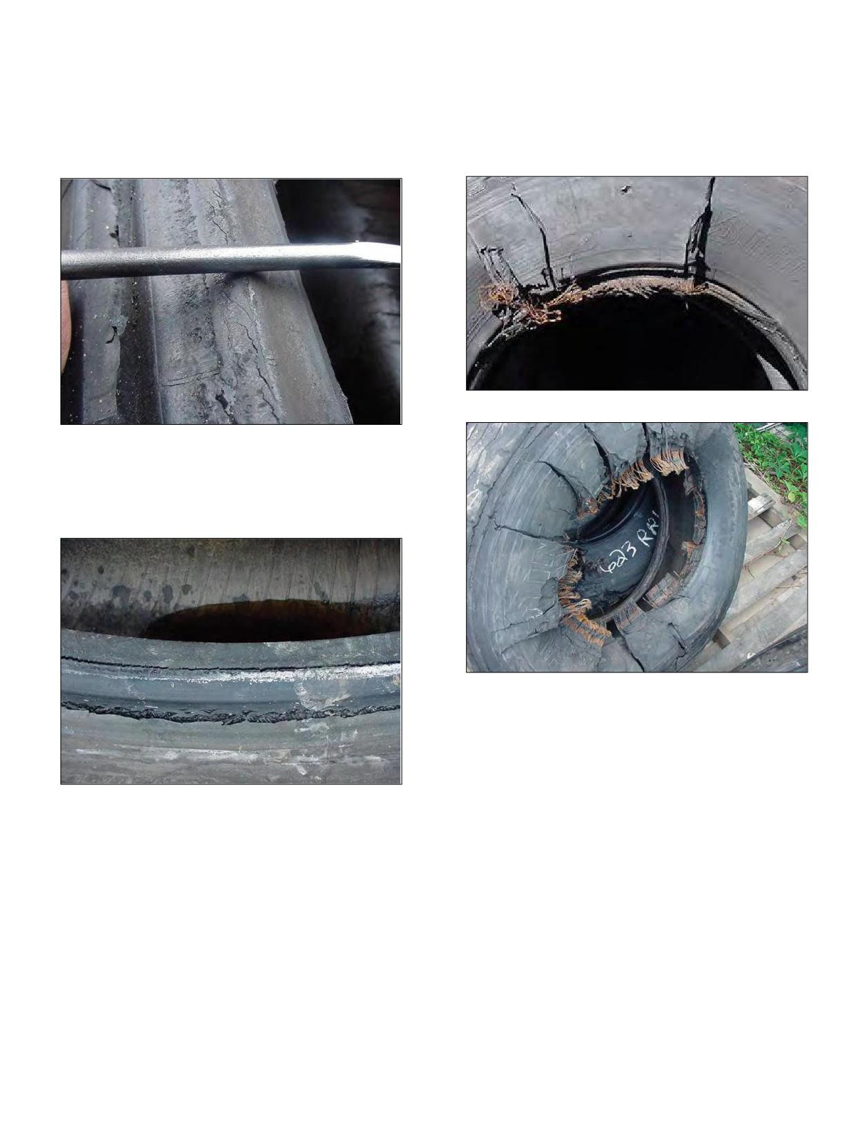
Bead damage as a result of brake heat is recognizable
The third stage is when the casing ply fully unwraps
in 3 stages of severity. In the first stage, the bead starts
from the bead. In extreme cases, the casing ply unwraps
to turn inward. This can be visibly identified on the tire
from the bead all the way around the tire. At this point
when it is dismounted. A straight edge placed across the
the tire completely separates from the bead wire. The
beads from one bead to the other no longer rests on the
bead wire can entangle itself around the axle if this type of
beadpoint, but nowrestscloser to the bead bearingarea.
separation occurs.
3rd Stage - Partial Unwrapping of the Casing Ply
1st Stage - Turning of the Bead
The second stage occurs when the rubber in the bead
area starts to split or crack indicating that the steel casing
plies are starting to unwrap.
3rd Stage - Complete Unwrapping of the Casing Ply
2nd Stage - Bead Splitting from Heat
Section Five: MICHELIN® X One® Tires
97
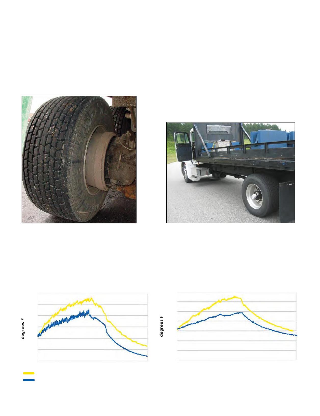
BRAKE HEAT EVALUATION:
This effect was demonstrated on a closed course at the
Laurens Proving Grounds, Michelin’s 3,000 acre test facility.
MICHELIN® X ONE® TIRES VS DUALS
MICHELIN® X One® tire fitments have greater clearance
The Test
between the brakedrum andthe bead of the tire compared
A 4x2 straight truck outfitted with a temperature logging
to a dual assembly. In addition, due to the 2” outset of the
device was loaded to maximum legal limits and operated
wheel for the MICHELIN® X One® tires, more brake drum is
on a closed course with almost continuous starting and
exposed, which provides greater air flow around the drum.
stopping cycles. The truck was brought up to 30 mph and
These characteristics reduce the heat transfer from the
then stopped repeatedly for 45 minutes. The temperature
brakesto the tire and allow the brakes to run cooler.
logging device recorded brake drum and wheel
temperatures (in the bead area) every 10 seconds. The test
was run on both MICHELIN® X One® tires and duals at
similar track temperatures and weather conditions.
Exposed Brake Drum
After 45 minutes, when the brakes were at their peak temperature, the temperatures from the data loggers were compared.
The brake drums fitted with MICHELIN® X One® tires were over 100°F cooler and the wheels were over 30°F cooler in the
bead area than when equipped with Duals!
BRAKE TEMPERATURE
WHEEL TEMPERATURE
MICHELIN® X ONE® TIRES vs DUALS
MICHELIN® X ONE® TIRES vs DUALS
220
700
200
600
180
500
160
400
140
300
120
200
100
100
80
Dual
Source: Recent evaluations at a Michelin facility in South Carolina.
MICHELIN® X One® Tire
98 Section Five: MICHELIN® X One® Tires
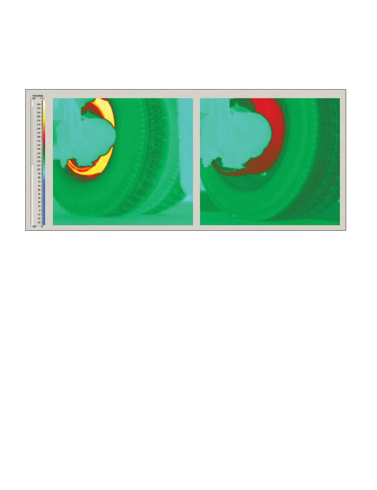
Thermal Imaging
The thermal image photos were captured after the
temperaturesonMICHELIN® XOne® tireequipped
repeated stopping test followed by 30 minutes of driving
vehicles will be significantly cooler than brakes on trucks
without braking. A brake drum temperature advantage for
running conventional duals. This effect will be most
theMICHELIN® XOne® tireof 90°Fwasstill apparenteven
pronounced during periods of heavy braking but will
after the cool down period.
persist for some time after braking has ended.
It issafe to say that for any given truck, brake
Dual Tires
MICHELIN® X One® Tire
Max temp ~ 215°F
Max temp ~ 180°F
Source: Recent evaluations at a Michelin facility in South Carolina.
Section Five: MICHELIN® X One® Tires
99
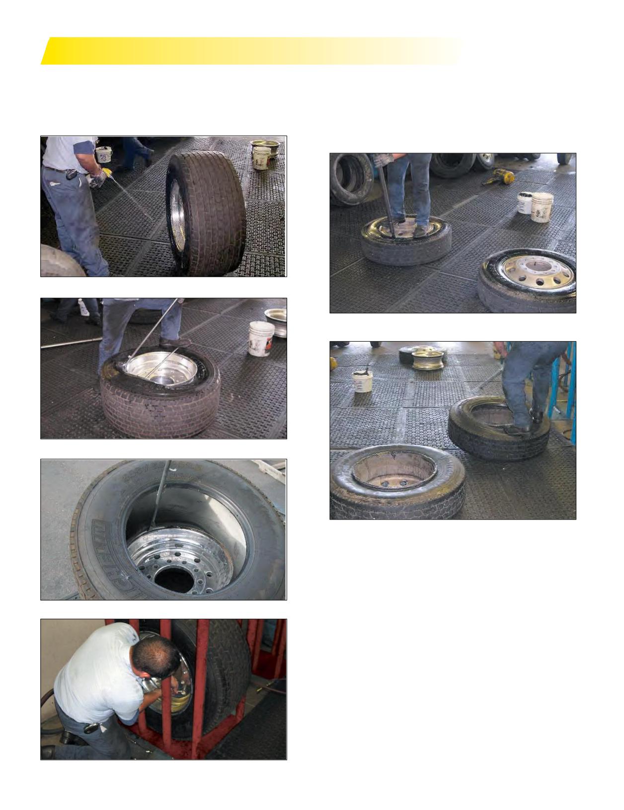
TIME LABOR STUDY - MICHELIN® X ONE® TIRE VS DUAL ASSEMBLY
MICHELIN® X ONE® TIRE ASSEMBLY
DUALS ASSEMBLY
• One tire and wheel: deflating, demounting,
• Two tires and wheels: deflating, demounting,
re-mounting, and re-inflating.
re-mounting, and re-inflating.
• Average time for one assembly is around 13-14 minutes.
• One inflation line.
• Average time for two assemblies is around 18-19 minutes.
Lubricating Beads for Dismount
Demounting Dual
Demounting MICHELIN® X One® Tire
Re-mounting Dual
Having a second inflation line will cut down the time by
about one third. With multiple inflation lines, the time is
similar to the MICHELIN® X One® tire.
Re-mounting MICHELIN® X One® Tire
Re-inflating MICHELIN® X One® Tire
100 Section Five: MICHELIN® X One® Tires
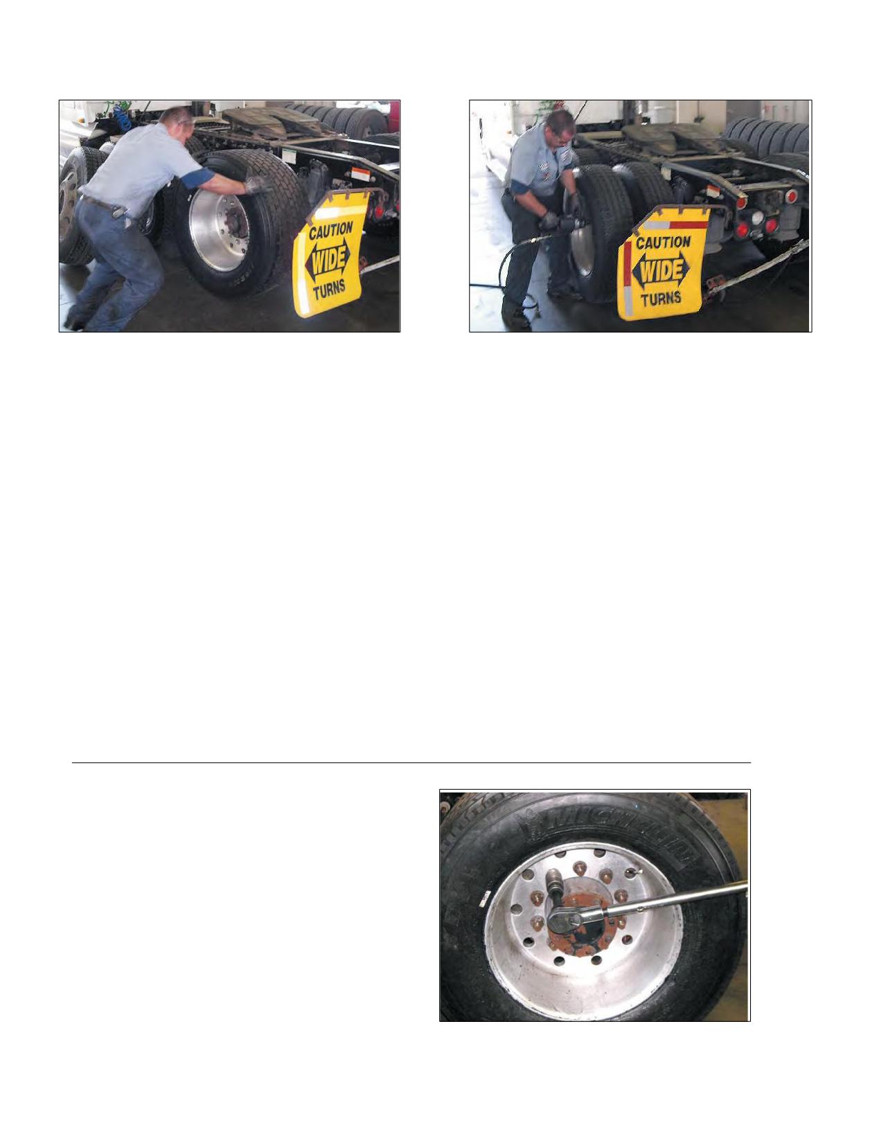
MOUNTING ON VEHICLE -
MOUNTING ON VEHICLE -
MICHELIN® X ONE® TIRE
DUALS
Mounting MICHELIN® X One® Tire on the Vehicle
Mounting Dual on the Vehicle
HUB PILOTED SINGLE
HUB PILOTED DUAL
1 assembly
2 assemblies
10 flange nuts (Either side)
10 flange nuts (Either side)
STUD PILOTED SINGLE
STUD PILOTED DUAL
2 assemblies
4 assemblies
10 Cap nuts (Left side)
10 inner cap nuts (Left side)
10 Cap nuts (Right side)
10 inner cap nuts (Right side)
10 outer cap nuts (Left side)
10 outer cap nuts (Right side)
(22 Parts)
(44 Parts)
In addition, dual wheelsmust be clocked for valve
stem access through the hand holes.
Mounting on hub-centered axles for the MICHELIN® X One® tire or Dual should take ~ 2 minutes for each axle end.
While mounting Dual on axles with stud-centered hubs, additional time is required due to the installation of an inner
andouter nutfor eachstud andhaving toline uphand holes.
TORQUE
Once the tire and wheel assembly is mounted onto
the axle end using an air gun, the final torque of each
wheel nut must be applied using a calibrated torque
wrench to 450-500 foot-pounds. This is a safety
procedure that will help prevent loose and broken
components and potential wheel-offs.
Torque Wrench
Section Five: MICHELIN® X One® Tires
101
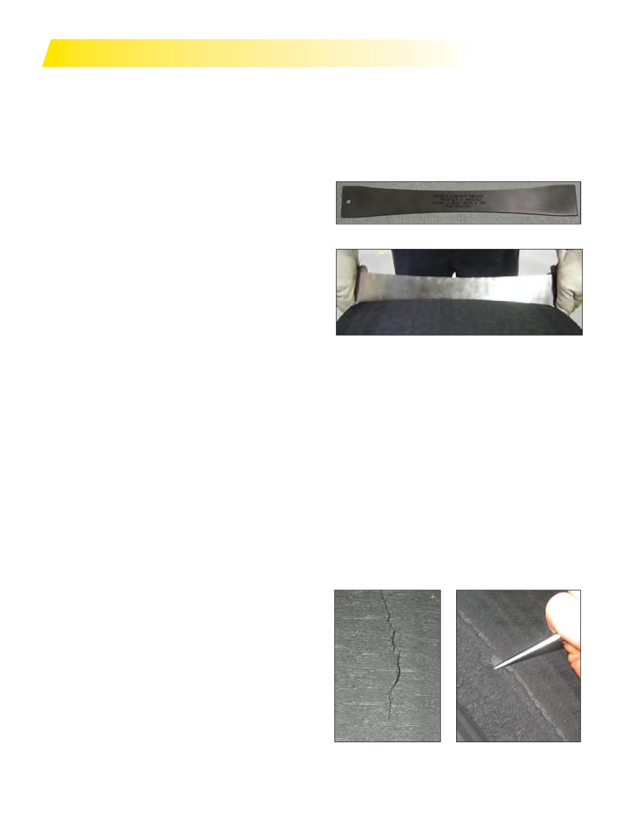
RETREAD AND REPAIR RECOMMENDATIONS
MICHELIN® X ONE® TIRE RETREAD AND
USING BUFFING TEMPLATES
REPAIR RECOMMENDATIONS
Check buff radius with the template after removing the
The MICHELIN® X One® tire may require some special
tire from the buffer. A 2mm gap is acceptable in the center
equipment to handle the wider tread and casing, it does not
of buffed surface when checking with the template.
require any special procedure to be repaired or retreaded.
NOTE: 1700 mm Buffing Template as available from
As with any tire, special care should be given to respect
TECH INTERNATIONAL (1-800-433-TECH/1-800-433-
the recommendations and guidelines associated with the
8342) See Pictures 1 and 2.
specific product to ensure optimum performance.
INITIAL INSPECTION
Inspect the MICHELIN® X One® casings as defined
Picture 1 - Buffing Template
by your retread process manufacturer or industry
recommended practices using appropriate equipment.
When using an electronic liner inspection device (such
as the Hawkinson NDT), a new wide base probe of at least
275 mm / 10.9 inches is required to insure sufficient and
consistent cable contact with the shoulder/upper sidewall
area. (Hawkinson part # PROBE ASSEMBLY 009).
It is recommended to slow the rotation speed or make
several additional cycles to catch as many small punctures
Picture 2 - Buffing Template
as possible.
Recommendedtread width ranges are given on Page
SHEAROGRAPHY
68 and may vary depending on the type and condition of
the MICHELIN® X One® casing. The MICHELIN® X One®
If using laser shearography inspection adjust and or
casing’s finished buffed measured width should follow the
modify to insure complete imaging shoulder to shoulder,
samestandards as other casings: treadwidth + 8 mm/-2mm.
per equipment manufacturer. Also make sure the correct
vacuum level is applied.
AFTER BUFF INSPECTION
If after buffing, circumferential cracks or splits remain
BUFFING
in one or both shoulders of the tire in the vicinity of the
An expandable rim width of 14.5 inches is required.
outside tread groove (Picture 3), the crack or split should
Buffi on a narrower rim can result in excess under-tread
be probed.If the probing penetrates into steel or feels soft/
on the shoulder, thereby increasing the operating belt edge
loose material, the casing should be rejected. This should
temperature. The beads of the casing should be lubricated
not be confused with a 360 degree product interface line that
with a fast drying tire lubricant. Runs of MICHELIN®
sometimesisvisible after buff(Picture 4). If this line is visible,
X One® tires should start with new blades which should
it should be probed and if found to be loose material, reject
be changed as soon as the buff texture starts to degrade.
the casing. If it is tight, continue the retread process.
Buffi should not start before the casing reaches target
pressure in the expandable rim as defi
by your retread
process manufacturer. Recommended minimum infl
pressure is 1.2 bars or 18 psi, maximum infl
pressure is
1.5 bars or 22 psi. Recommended buffi radius for pre-cure
fl treads (w/o wings) is 1700 mm ± 50 mm or 67 inches ± 2
inches.
Picture 3
Picture 4
102 Section Five: MICHELIN® X One® Tires
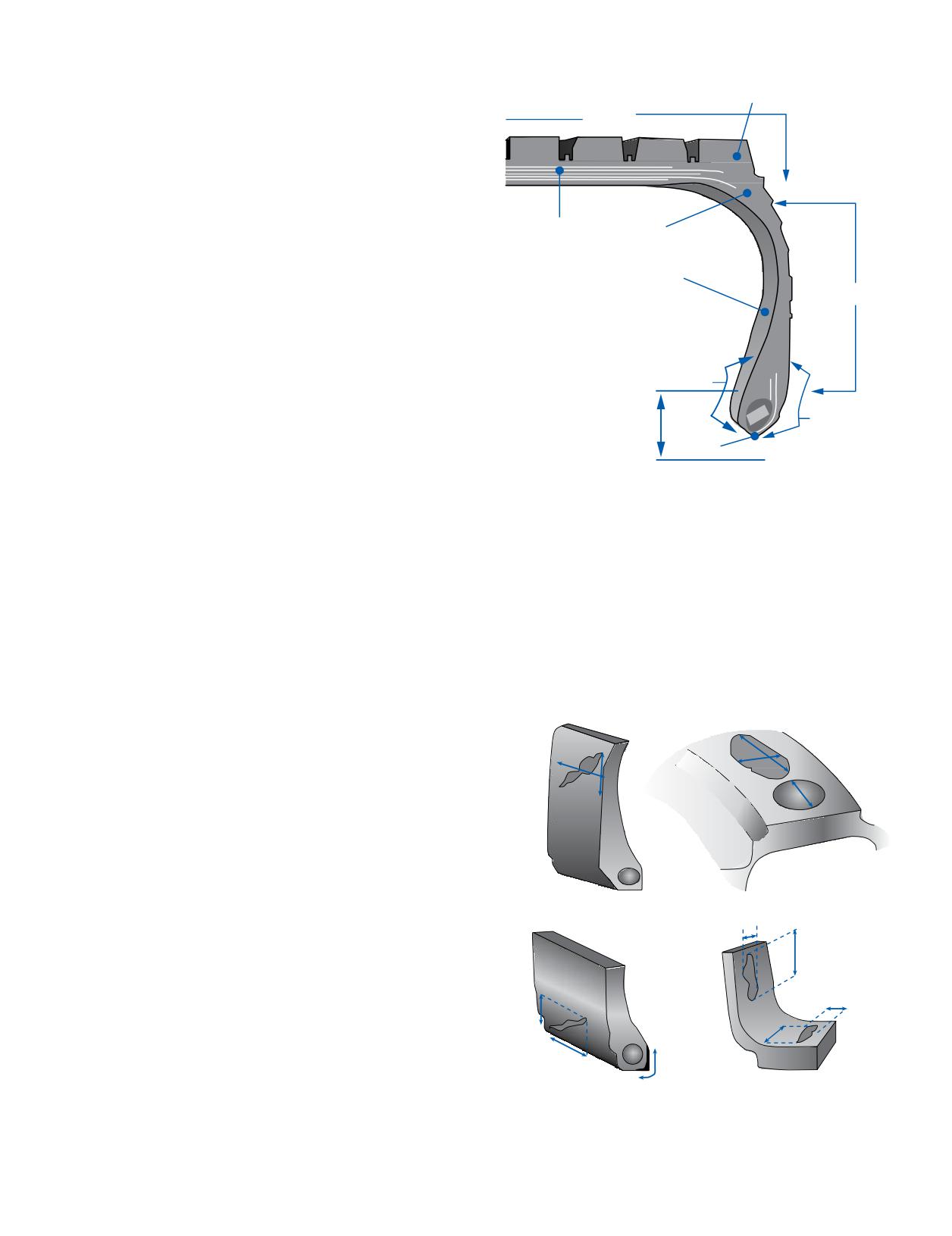
BUILDER
Principal Components
Expandable rim width of 14.5 inches is required.
Shoulder
Tread table rollers should be completely cleaned before
Crown
and/or after each build series. The base of the wider
MICHELIN® X One® tread will come in contact with the
roller’s outer edges, so care should be taken to prevent
contamination by cleaning the rollers at frequent intervals.
Tread building should not begin until tire pressure has
Crown Plies
reached the target inflation pressures in the expandable
Body Ply
rim as defined by your retread process manufacturer.
For cushion to casing extruded bonding gum
Inner Liner
application, recommended minimum inflation pressure
Sidewall
is 0.8 bar or 12 psi. Bonding gum thickness should not
exceed 1.5 mm (2/32 inch) in the crown and 2.5 mm (3/32
A
A’
inch) in the shoulders.
Note: For non-Michelin wing tread products, contact
75 mm
MRTDuncan, SC at 1-888-678-5470, then press 3 for
C
Technical Support.
75 mm
10 mm
Bead
B
ENVELOPING
B
Contact your envelope supplier for the recommended
size envelopes to be used.
Note: For truck sizes, point B is considered the “toe” of
the bead. Point A is found 75mm from point B towards
CURING
the interior of the casing, and point A’ is also 75 mm from
Cure the MICHELIN® X One® casing according to
point B but is located on the exterior of the casing. Point
cure law for the tread design per the retread process
C is located 10mm from point B (measured as shown).
manufacturer.
Any repair patch material must be positioned >10 mm
from the toe of the bead (point B).
FINAL INSPECTION
Perform a final inspection of the MICHELIN® X One®
Damage Guidelines
casing according to the retread process manufacturer
work method and specification.
Note: The retreader is still responsible for determining
W
if the MICHELIN® X One® casing is capable of being
L
retreaded; the same as would be done for any other tire in
W
L
the inspection process.
D
Sidewall Damage
Crown Damage
W
L
L
L
W
W
L
Bead Damage
Interior Damage
Section Five: MICHELIN® X One® Tires
103

REPAIR RECOMMENDATIONS
Type of Repair
Application
Quantity Limits
Size Limits
Long Haul, Pickup &
Max 10 per sidewall
No limit
Delivery (P&D)
Spot Repair
(no body ply affected)
Severe Service
Max 20 per sidewall
No limit
Max width: 150 mm (6 in)
All
Max 4 per bead
Min distance between repairs: 75 mm (3 in)
Bead Repairs
(rubber damage only)
Severe Service
L = 2 mm x W = 50 mm (1⁄16 in. x 2 in)
No limit
(bead toe repair only)
Min distance between repairs: 75 mm (3 in)
Bead Repairs
L = 25 mm x W = 55 mm (1 in. x 2 in)
All
Max 4 per bead
(chafer strip)
Min distance between repairs: 75 mm (3 in)
If blister diameter is less than 5 mm (3⁄16 in),
leave intact;
Repair between 5 mm (3⁄16 in) and 20 mm (3⁄4 in)
Liner Repairs
All
No limit
If blister diameter is more than 20 mm (3⁄4 in),
reject casing
Max diameter: 40 mm
(1.6 in)
Long Haul, P&D
Max 15 per tire
Buzzouts
Max surface: 1600 mm2 (2.5 in2)
(protector ply of
3rd working ply)
Max diameter: 40 mm
(1.6 in)
Severe Service
Max 60 per tire
Max surface: 1600 mm2 (2.5 in2)
Max diameter: 30 mm
(1.2 in)
Long Haul, P&D
Max 3 per tire
Buzzouts
Max surface: 900 mm2 (1.4 in2)
(2nd working ply;
Infinicoil)
Max diameter: 30 mm
(1.2 in)
Severe Service
Max 20 per tire
Max surface: 900 mm2 (1.4 in2)
Nail Hole Repairs
All
Max 5 per tire
Max diameter: 10 mm
(0.4 in)
Crown
Max diameter: 25 mm
(1.0 in)
Section Repairs
All
Max 2 per tire
Sidewall
L 70 mm x W 25 mm (2.8 in x 1.0 in)
L 90 mm x W 20 mm (3.8 in x 0.8 in)
L 120 mm x W 15 mm (4.7 in x 0.6 in)
For up to 6 mm nail hole repairs in the shoulder area, the repair unit should be upsized (larger than CT20) and offset to move the reinforcement
end as far away from the maximum flex area as possible.
RETREAD RECOMMENDATIONS
Tread Width
Casing Size
Buff Radius (1)
Circumference
Tread Type
Min
Max
1700 mm (± 50 mm)
3070 mm
Flat Tread
380 mm
390 mm
445/50R22.5
or
or
67 inches (± 2 inches)
121 inches
Wing Tread (2)
375/420 mm
385/430 mm
1700 mm (± 50 mm)
3225 mm
Flat Tread
390 mm
400 mm
455/55R22.5
or
or
67 inches (± 2 inches)
127 inches
Wing Tread (2)
385/430 mm
395/440 mm
1. For MRT Custom Mold™ Retread the buff radius should be 2200 mm (87 in).
2. For non-Michelin wing tread sizes contact MRT Technical Support at 1-888-678-5470, Option 3.
104 Section Five: MICHELIN® X One® Tires
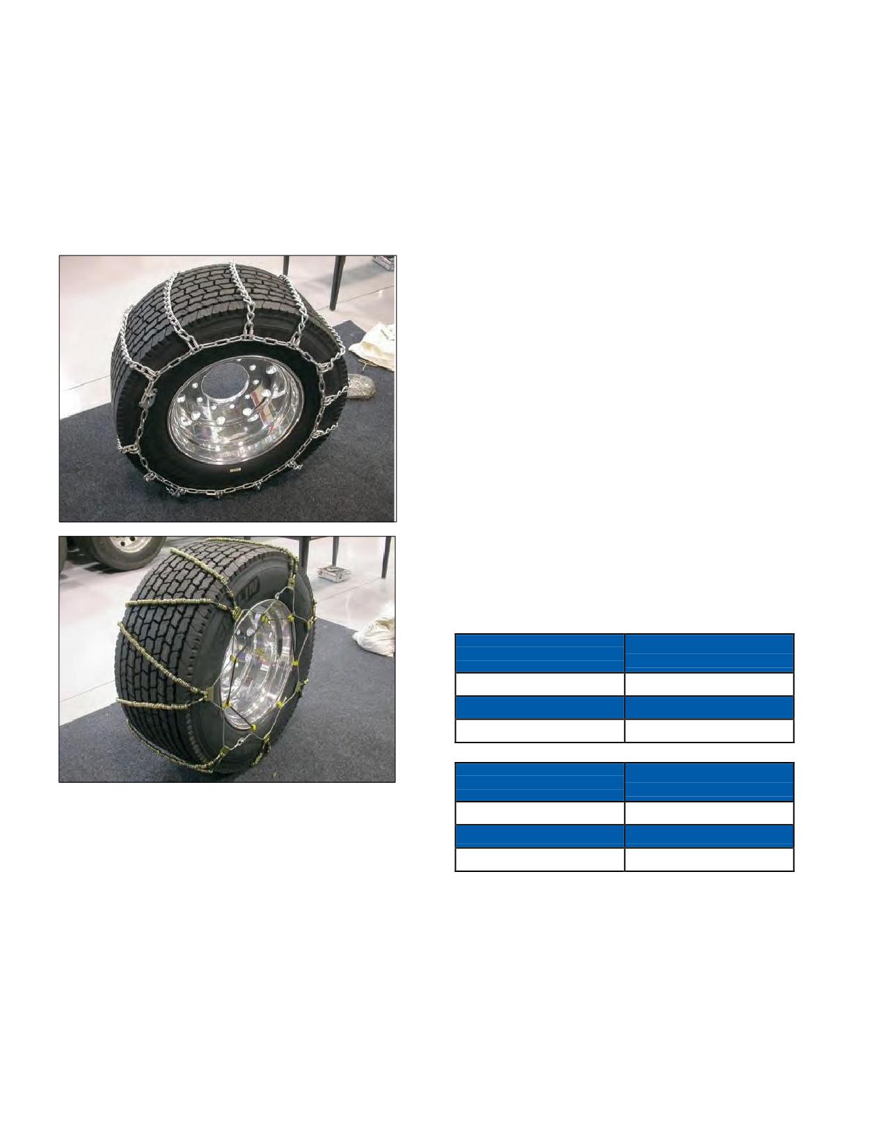
CHAINS*
GEAR RATIO
Depending on the state in which you are traveling,
A change in tire dimension will result in a change in
chainsmay ormay not be required. If chains are
engine RPMat a set cruise speed** that will result in a
required, several companies have chains available for the
change in speed and fuel economy. The effect of tire size
MICHELIN® X One® tire. The thing to remember when
change on gear ratio should be considered in individual
purchasingchainsforyourMICHELIN® X One® tireis the
operations.
tire size, as the 445/50R22.5 chains don’t fi the 455/55R22.5
A decrease in tire radius will increase tractive torque and
and vice versa. For more information, consult your local
increase indicated top speed. An increase in tire radius will
dealer or go to www.tirechains.com.
reduce tractive torque and decrease indicated speed.
Tire Revs./Mile - Speed - Size: These factors can affect
engine RPM ifcorrespondingchangesarenotmade to
engine ratios.
Example: Going from larger diameter tire to smaller
diameter tire.
If you currently run a 275/80R22.5 MICHELIN® XDN®2
tire (511 Tire Revs./Mile) and change to a 445/50R22.5
MICHELIN® X One® XDN®2 tire (515 Tire Revs./Mile),
the speedometer will indicate a slightly higher speed than
the actual speed the vehicle is traveling.
Final Tire Revs./Mile - Initial Tire Revs./Mile =
Initial Tire Revs./Mile
515 - 511 = 0.0078 or 0.78% (< 1% change)
511
So when your actual speed is 60 mph, your speedometer
will read 60.47 mph.
** Exceeding the legal speed limit is neither recommended nor endorsed.
MICHELIN® X One® Tire
MICHELIN® X One® Tire Size
Tire Revs./Mile
445/50R22.5
515 (X One XDN2)
Dual Size
Dual Tire Revs./Mile
275/80R22.5
511 (XDN2)
MICHELIN® X One® Tire
MICHELIN® X One® Tire Size
Tire Revs./Mile
* The information provided is for reference only.
Chain-specific questions should be directed to the chains
455/55R22.5
492 (X One XDN2)
manufacturer.
Dual Size
Dual Tire Revs./Mile
11R22.5 or 275/80R24.5
496 (XDN2)
Section Five: MICHELIN® X One® Tires
105
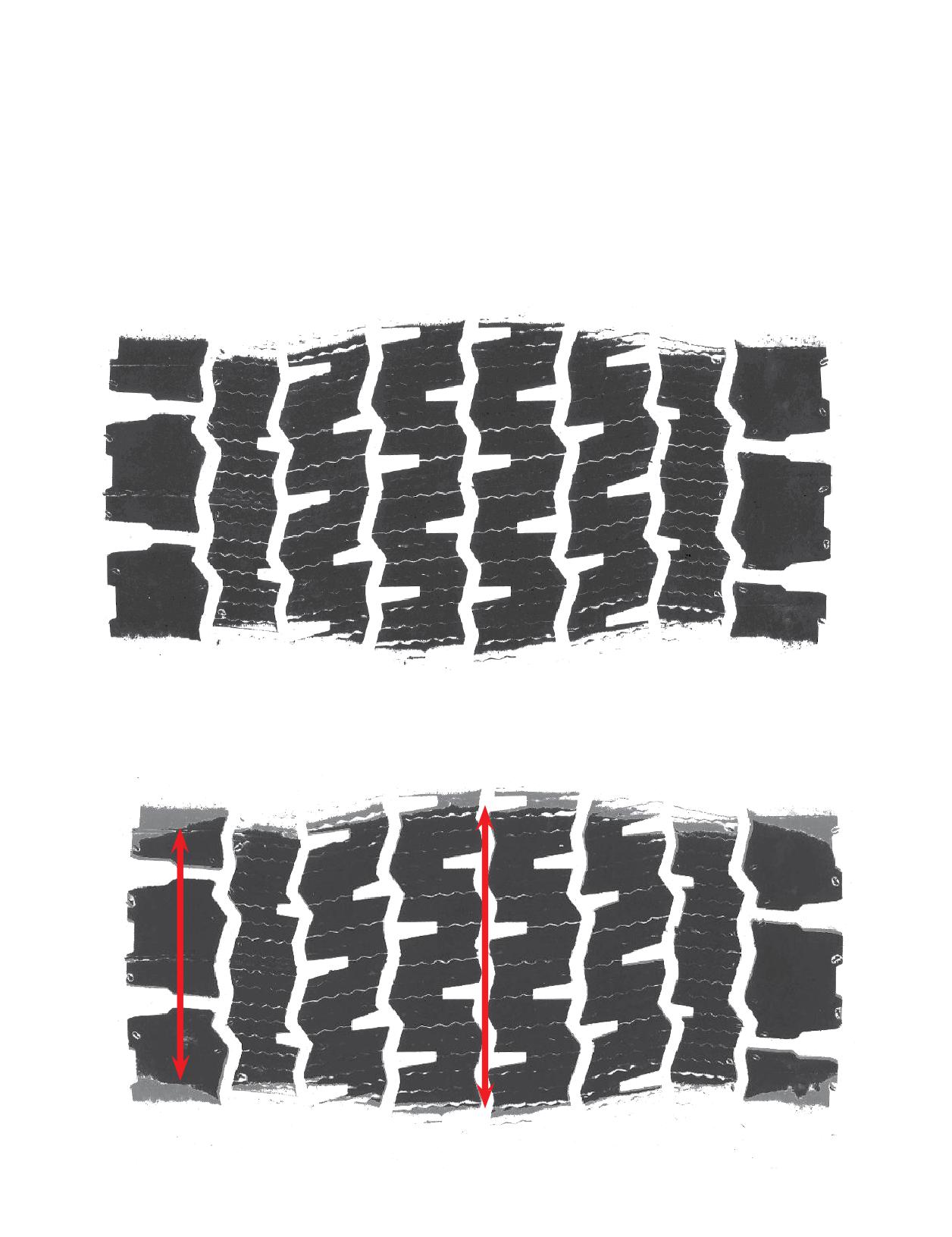
FOOTPRINT COMPARISONS TO DUAL TIRE FITMENTS
MICHELIN® X ONE® XDN®2 TIRE - 445/50R22.5 versus MICHELIN® XDN®2 TIRE - 275/80R22.5
Take notice that switching to single tire fitments causes
support the loads your fleet encounters as defined in
a slight reduction in footprint area when compared
the MICHELIN® Truck Tire Data Book (MWL40731).
to dual. This will not have a negative impact on your
Overinflation of the MICHELIN® X One® tires will
traction.
not only reduce the footprint but can adversely affect
The MICHELIN® X One® tire footprint will be dependent
handling, wear, and ride characteristics. Overinflating
on pressure recommendations and vehicle loads. One
tires may also result in exceeding the wheel’s maximum
should always select a pressure that will adequately
pressure.
445/50R22.5 MICHELIN® X ONE® XDN2® AT 100 PSI
120 PSI FOOTPRINT OVERLAID ON 100 PSI FOOTPRINT
The photo below demonstrates what occurs to the footprint when you overinflate the same tire to
120 psi. The overinflated footprint’s length and width are reduced (black footprint) when compared
to 100 psi footprint (gray footprint).
Shoulder: -22 mm
Center: -12 mm
106 Section Five: MICHELIN® X One® Tires
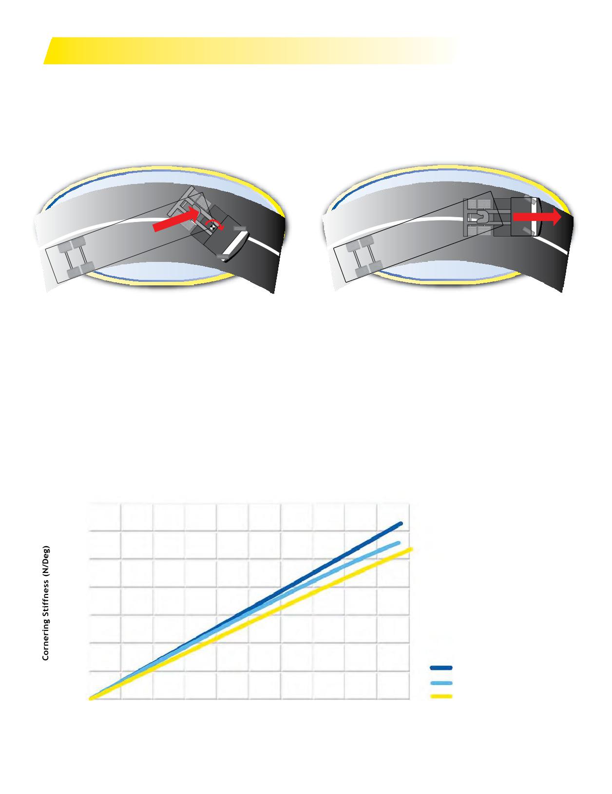
OPERATION AND HANDLING
OVER-STEER
UNDER-STEER
Over-steer is when the rear wheels are carving a larger
Under-steer is when the front wheels are carving a
arc than the front wheels or the intended line of the turn.
larger arc than the rear wheels. This is often described
This is often described as a “loose” condition, as the truck
as “push” or “pushing,” as the front end feels like it is
feels like the rear end is coming around.
plowing off of a corner.
Over-steer: Very Difficult to Correct
Under-steer: Very Easy to Correct
Over-steer is dangerous because once the rear end comes around, the vehicle
is uncontrollable and may enter a spin. Braking only makes this condition worse.
Under-steer is the more desirable condition because you have direct control over
the front tires, and deceleration usually corrects the condition.
The MICHELIN® X One® tire has a higher cornering stiffness and can generate
more lateral force than standard dual drive tires. Increasing cornering stiffness of
the rear tires promotes under-steer. Additionally, it will take more force to jack-
knife the vehicle.
CORNERING STIFFNESS FOR DIFFERENT TIRES
7,000
6,000
5,000
4,000
3,000
2,000
MICHELIN X One Tire
1,000
®
®
Two Dual
0
Conventional Wide-Base
0
5,000
10,000 15,000 20,000 25,000
30,000 40,000 45,000 50,000
Normal Force (N)
Source: Recent evaluations at a Michelin facility in South Carolina.
Section Five: MICHELIN® X One® Tires
107
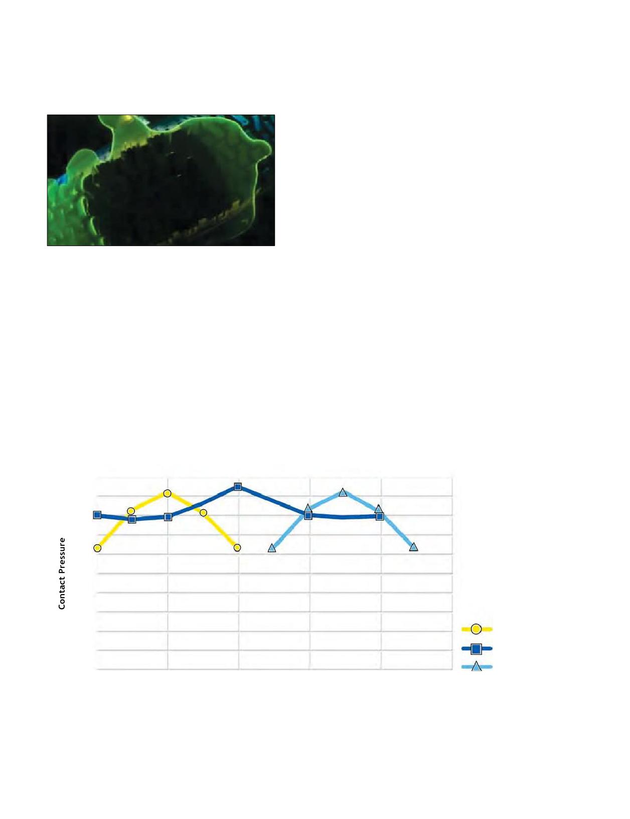
HYDROPLANING
A tire’s contact pressure can reduce your chance of
Hydroplaning occurs when the tire loses contact with
hydroplaning. The MICHELIN® X One® tire has higher
the road. This can happen when the water pressure
contact pressure at the edge of the tread, which provides a
exceeds the contact pressure between the tire and the
wider “sweet spot” than dual tires. In the graph below, you
road.
can see that the contact pressure is slightly higher in the
center and significantly higher at the shoulders over dual
fitments. Note the dropin contact pressure for dual tires on
the graph below.
For example, the contact pressure of a dual tire is about
90 psi compared to 116 psi for a MICHELIN® X One® tire.
This will result in the dual tire losing contact with the
road at lower speed than the MICHELIN® X One® tire.
This means if hydroplaning occurs at 60 mph for the
MICHELIN® X One® tire, it will occur at 53 mph on the
dual.
Contact Pressure Ratio = = (90/116) = 88% or
Factors that increase likelihood of hydroplaning:
60 mph x 0.88 = 53 mph
- Excess water
- Excessive speed
- Low tread depth
- High tire pressure
- Light loads or bob-tailing
In other words, if rain is pouring down and water is
pooling, the truck’s speedneeds to decreasein order to
avoid hydroplaning.
1,000
900
800
700
600
500
400
300
Dual Tire 1
200
MICHELIN® X One® Tire
100
Dual Tire 2
0
1
3
5
7
9
11
Rib Number
Source: Recent evaluations at a Michelin facility in South Carolina.
108 Section Five: MICHELIN® X One® Tires
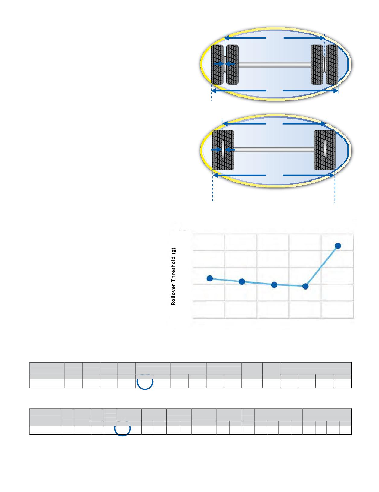
ROLLOVER THRESHOLD
Duals
There are two things you canchange tomake
77.5"
a vehicle more resistant to rollover:
Track Width
- Lowerthe center of gravity
- Increase your track width
0" Outset
The MICHELIN® X One® tire does both.
First, the loaded radius of the 445/50R22.5
MICHELIN® X One® XDN®2tire is 18.7”.
101.5"
A 275/80R22.5 MICHELIN® XDN®2 tire (dual
equivalent) loaded radius is 18.9”. See chart below.
X One Tires
For every inch you lower the Center of Gravity, you
gain 3 mph additional safety factor with regard to
80.5"
Track Width
rollover threshold.
Second, the track width is measured at the center
of where the load is distributed on the ground.
2" Outset
Fordual, this would bemeasured at the center of the
space between the dual. For the MICHELIN® X One®
tire, it is simply measured from the center of the left
97.9"
side tire to the center of the right side tire.
Asyoucansee,eventhoughtheoverallwidth
Note: Measurements are nominal values
and could vary with manufacturer.
has reduced, the track width has increased on the
MICHELIN® X One® tire.
ROLLOVER THRESHOLD WITH TIRE SIZE
In summary, the MICHELIN® X One® tire
0.42
improves rollover threshold by increasing
cornering stiffness, increasing track width, and
0.40
reducing the center of gravity.
0.38
These improvements have been validated with:
1) Computer simulation where the whole
0.36
vehicle is characterized mathematically.
2) Track testing at our internal proving grounds.
0.34
3) OE vehicle manufacturers in their independent
testing, including tilt table testing.
0.32
275/80R22.5 385/65R22.5 425/65R22.5 445/65R22.5
445/50R22.5
Source: Recent evaluations at a Michelin facility in South Carolina.
SPECIFICATIONS FOR TREAD DESIGN: MICHELIN® X ONE® XDN®2
Tread
Max.
Max. Load and Pressure
Load
Catalog
Loaded Radius
Overall Diameter
Overall Width (‡)
Approved
Revs
Size
Depth
Speed (*)
Single
Range
Number
Wheel
Per Mile
32nds
mph
in.
mm
in.
mm
in.
mm
lbs.
psi
kg.
kPa
445/50R22.5
L
36587
27
75
18.7
474
40.4
1026
17.1
435
14.00
515
10200
120
4625
830
SPECIFICATIONS FOR TREAD DESIGN: XDN®2
Max.
Approved
Tread
Loaded
Overall
Overall Width
Min. Dual
Revs
Max. Load and Pressure
Max. Load and Pressure
Load
Catalog
Speed
Wheels
Size
Depth
Radius
Diameter
(‡)
Spacing (‡) Per
Single
Dual
Range
Number
(*)
(Measuring wheel
32nds
mph
in.
mm
in.
mm
in.
mm
listed first.)
in
mm
Mile
lbs.
psi
kg.
kPa
lbs.
psi
kg.
kPa
275/80R22.5 (1)
G
63465
27
75
18.9
481
40.6
1030
11.0
279
8.25, 7.50
12.2
311
511
6175
110
2800
760
5675
110
2575
760
Section Five: MICHELIN® X One® Tires
109
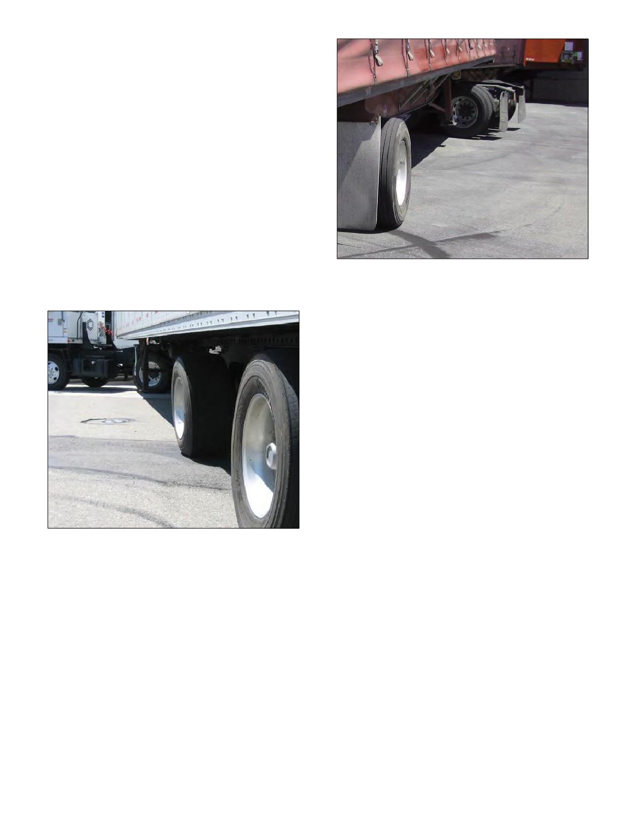
JACK-KNIFE
When you put the tractor and trailer into an extreme
turn or “jack-knife” situation, the trailer is very vulnerable
to rollover.
Normally, traction has a positive influence on the
handlingof the truck. This is nolonger true when you put
a truck in a jack-knife condition. Whether dual or single
configuration, you are forcing the tires to stop rolling and
slide sideways. As the photo below clearly demonstrates,
the trailer is twisting because the tires are holding their
position on the road. This can lead to rollover!
This is especially true for spread axle trailers and high
center of gravity loads. Look at the lateral stress placed
on the tires from the jack-knife situation. Turning angles
should be minimized to avoid rollover threshold whether
operating with duals orMICHELIN® XOne® tires.
Turning angles should be minimized to avoid rollover
threshold whether operating with duals or MICHELIN®
X One® tires.
110 Section Five: MICHELIN® X One® Tires
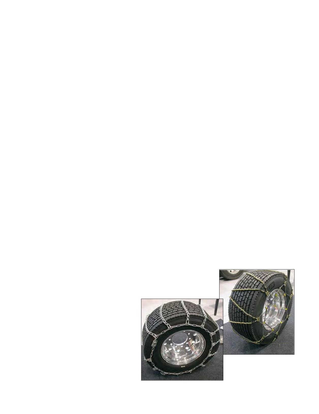
NEVER exceed vehicle limitations because of improved
This can be simplified by remembering the following:
handling.
A tire with a wider footprint is going to provide
DROP
increased lateral stability when cornering. As a result
ROLL
of this increased lateral stability, the truck will have a
tendency to lean less in turns. The increased lateral
and STOP
stability should not equate to increased speed. Always
obey posted speed limits on the highways and curves.
In other words, the vehicle lean or DROP may be the
A good rule of thumb for vehicles with high rollover
first indication of a rapid tire pressureloss. Don’t jam on
thresholds (i.e., tankers, concrete mixers) is to take the
the brakes! Pumping the brakes will allow the damaged
curves at the posted limit less 10 mph.
wheel end to ROLL to a STOP without lock-up.
There are many MICHELIN® X One® tire training videos
RAPID TIRE PRESSURE LOSS PROCEDURE
including rapid tire pressure loss handling, and specific
Even though the MICHELIN® X One® tire is an
application demonstrations. To obtain one of these,
innovative product, it still requires proper pressure
contact your local Michelin dealer or the Michelin sales
maintenance and visual inspection practices. Tire failure
representative in your area.
can and will occur.
Below you will find a handy reference of the procedure
TRACTION
to bring the vehicle to a safe stop following a rapid tire
Traction is dependent on the following variables:
pressure loss event:
- speed
- tread depth
Indications:
- conditions (dry or wet, depth of water)
(Some or all of the following may apply.)
- tread design
- No change in handling
- tread rubber compound
- Slight lean (depending on wheel position)
- road surface (concrete, asphalt)
- Vibrations
- Audible noise when rapid tire pressure loss occurs
CHAINS*
Dependingonthestateinwhichyouaretraveling,
Immediate Actions:
chainsmay ormay not be required.If chainsare
- Accelerate enough to maintain lane position.
required, several companies have chains available for
(DO NOT apply brakes immediately.)
the MICHELIN® X One® tire. The thing to remember
- Do not apply maximum brake pressure to bring the
when purchasing chains for your MICHELIN® X One®
vehicle to a stop. This stop should be gradual by
tire is the tire size, as the 445/50R22.5 chains don’t fi the
pumping the brakes.
455/55R22.5 and vice versa. For more information, consult
- Creating assembly lock-up can cause irrepairable
your local dealer or go to www.tirechains.com.
damage to tire, wheel, axle components, and vehicle.
- Pull the vehicle to a safe area.
- Do not attempt to limp further down the road.
Secondary Actions:
- Turn on flashers
- Deploy safety triangles
- Inspect vehicle for damage
– Call for assistance
* The information provided is for
reference only. Chains-specific
questions should be directed to
the chains manufacturer.
Section Five: MICHELIN® X One® Tires
111
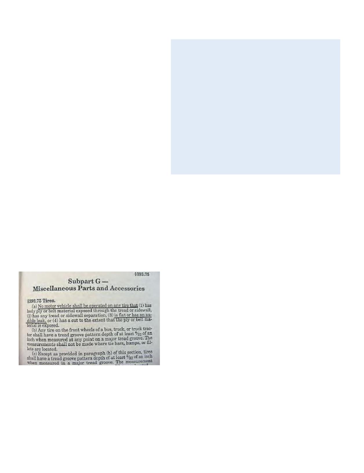
STOPPING DISTANCES
The following provides the top ten reasons not to limp home on
any tire.
Stoppingdistance with theMICHELIN® XOne®
tire is similar to that of a vehicle in dual
configuration. A general rule typically mentioned
TOP REASONS
in Commercial Driver’s License (CDL) manuals is
NOT TO LIMP HOME
10
to allow one vehicle length or one second between
your vehicle and the one you are following for every
10. Pavement Damage: when the tire is run to destruction,
the wheel contact damages the road.
10mph of your velocity. For example: if you are
9. Wheel Damage: $$$ hundreds of dollars.
driving at 65 mph, allow 6.5 seconds between your
8. Destroyed Casing: it may have otherwise been repairable.
vehicle and the one in front of you. A good way to
$$$ hundreds of dollars.
7. Cargo Damage: load shifts, collisions, roll-overs or fires.
practice this is to mark a spot, such as a bridge,
6. Collateral Truck Damage: fairings, tanks, hoses, brakes,
road sign, etc., that the vehicle you’re following
hoods, mudflaps, etc.
5. Wheel and/or Tire Detachment: if the tire/wheel become
has just passed and count one-one thousand, two-
detached, they become a projectile.
one thousand, etc., to see how long it takes you to
4. Adverse Handling Conditions: mishandled, a run-flat could
reach the same point. If you count to only four-one
lead to a jack-knife or even a roll-over.
3. Direct DOT Violation: fines/downtime/out-of-service.
thousand, then increase your following distance.
2. Creating assembly lock-up can cause irrepairable damage
In wet and/or icyconditions, do not assumethat
to tire, wheel, axle components, and vehicle.
because you have better traction you will be able to
1. Endangers Other Vehicles and People: heavy duty truck
accidents can be fatal.
stop quicker. It is always the best practice to increase
following distances and reduce driving speeds when
traveling in adverse weather conditions.
STATE AND LOCAL REGULATIONS
Some states have enacted “Load Per Inch Width” regulations for
LIMPING HOME
the purpose of governing axle weight on (primarily) the steering axle
Limping on the MICHELIN® X One® tire can cause
of commercial vehicles. These regulations provide a carrying capacity
damage to the wheel and casing. Although the tire
of a certain number of pounds per each cross-sectional inch across
is down, it’s possible that it is repairable unless it
the tire’s width. The determination of the tire’s width can vary from
was run-flat. Limping home is never recommended
state to state, but presumably would be based upon either the tire
evenondualtires. Limpingis a direct CSA
manufacturer’s published technical data for overall width, or the
(Comprehensive Safety Analysis) violation.
width asmarked on the sidewall of the tire (whichmay require
DOT (Department of Transportation) Regulation
conversion from Metric to English units). It is recommended to
393.75 states:
contact your state’s DOT office to confirm the current “Load Per Inch
Width” law.
Forexample, if a state allows for 550 pounds per inch width, a tire
marked 445/50R22.5 could carry up to 9,636 pounds (17.52 x 550) or
atotal of 19,272 pounds onthedrive axle(2 x 9636). Another way to
look at it is to take the total weight carried and divide by the stated
“Load Per Inch Width” law to determine the appropriate size tire.
If a truck needs to carry 16,000 pounds an axle in a state with a 500
pound per inch width limit (16000/500 = 32), you would need a
wide single tire that is at least 16 inches wide (32/2). In this case a
445/50R22.5 could legally carry the load (445 mm/25.4 mm per inch =
17.5 inches Metric to English conversion).
The two formulas are:
Load Per Inch Width Law x Tire Section Width x Number of Tires =
Gross Axle Weight Limit
Gross Axle Weight/Inch Width Law/Number Of Tires =
Minimum Tire Section Width Needed
State laws and regulations frequently can and do change, so it is
recommended that you consult your local State or Province DOT and
where you will be traveling to be sure there are no restrictions on
the use of the MICHELIN® X One® tire for your particular operation,
equipment, and weight.
112 Section Five: MICHELIN® X One® Tires
SECTION SIX
MICHELIN
® RV Tires
Section Six
MICHELIN® RV Tires
113-124
MAINTAINING RECREATIONAL VEHICLE TIRES
114-120
The Importance of Inflation Pressure
Inflation Pressure Requirements
When to Check Recreational Vehicle Tire Pressure
Tire Repairs
Tread Depth Measurements and Wear Bars
Dual Spacing
Directional Tires
Tire Pressure Monitoring Systems (TPMS)
Nitrogen
Workmanship and Materials
Location of Tire Identification Code
Service Life for Recreational Vehicle Tires
Selecting Alternative Tire Sizes
Drive at Proper Speeds
Long Term Storage
Aging, Weather Checking, and Ozone Cracking
Proper Cleaning of RV Tires
Tire Rotation, Balance, Alignment and Tire Wear
Common Tire Damages
HOW TO WEIGH THE RECREATIONAL VEHICLE
121-124
How to Weigh the RV
Three Different Types of Scales
Weighing the Single Axle Recreational Vehicle
Weighing the Tandem Axle Recreational Vehicle
The Effect of Towed Vehicles or Trailers
How to Use the Actual RV Weight Information
with the Tire Data Load Chart
Using Blocks to Level Motorhomes and RVs Equipped
with Radial Tires
For additional information about
MICHELIN® RV Tires, refer to the
- business.michelinman.com
- MICHELIN® Truck Tire Data Book - MWL40731
Section Six: MICHELIN® RV Tires
113
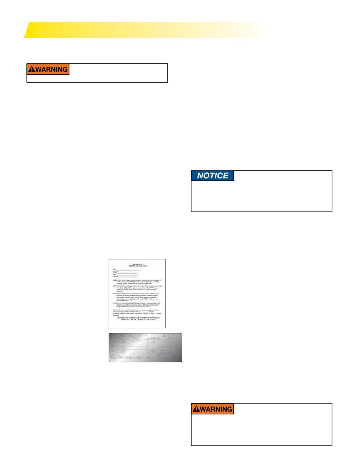
MAINTAINING RECREATIONAL VEHICLE TIRES
The GCWR (Gross Combination Weight Rating) is the
THE IMPORTANCE OF INFLATION
value specified by the recreational vehicle manufacturer
PRESSURE
at themaximumallowableloadedweightwithatowed
Never drive on an overloaded
trailer or towed vehicle.
or underinflated tire.
These ratings can vary based on the different
components and vehicle options. To determine proper
The most critical factor in tire maintenance is proper
inflation pressure, Michelin recommends weighing each
inflation. Driving on any tire that does not have the
wheel position of the recreational vehicle individually.
correct inflation pressure is dangerous and will cause tire
Weighingeachaxleendindividually will give a clear
damage. Improper pressure for the weight of the vehicle
indication of how the weight of the recreational vehicle is
could cause premature wear, tire damage, or a harsher
distributed across the axle. If there is a difference in the
ride. The correct inflation pressure allows for full tread
weight found from one side to the other, adjust personal
contact with the road surface and promotes traction,
cargo within the vehicle in order to redistribute the load
braking capability, and handling.
more evenly across the axle.
An underinflated or overloaded tire will build up
For instructions on how to weigh a recreational vehicle,
more heat that could go beyond the endurance limits
see pages 121-124.
of the rubber, steel belts, and radial cords. This could
cause sudden tire failure. Underinflation will cause
poor handling, faster and/or irregular tire wear, and a
REMEMBER: For control of the recreational
vehicle, it is critical that the tire inflation
reduction in fuel economy. Overinflation, on the other
pressures are set to the same inflation pressure
hand, will reduce the tire’s contact area with the road
across an axle.
surface, which reduces traction, braking ability, and
handling. A tire that is overinflated for the weight it is
WHEN TO CHECK RECREATIONAL VEHICLE
carrying is more prone to a harsh ride, uneven tire wear,
TIRE PRESSURE
and impact damage.
For optimum performance and handling, it is important
to not only establish the proper inflation pressure, but
INFLATION PRESSURE REQUIREMENTS
it is also important to regularly inspect recreational
The amount of inflation
vehicle tires for cuts, snags, and penetrations. Failure to
pressure required in each tire
maintain correct inflation pressure may result in sudden
depends on the weight of the
tire destruction and/or improper vehicle handling.
fully loaded vehicle, to include
Additionally, it will result in irregular tire wear. Check
passengers, cargo load, fuel,
inflation pressures on all tires (including spares):
and water. To determine the
1. At a minimum, check weekly, and always before long
correct inflation pressure,
distance trips.
consider the various weight
2. On long trips, check every morning before driving.
ratings that are posted on the
3. Before and after storage, check and record tire
recreational vehicle chassis, or
pressures (a drop in pressure may indicate a slow
within the recreational vehicle
leak).
itself. The GVWR and the GAWR
The ideal time to check tire inflation pressures is early
stickers are normally located
morning. Driving, even for a short distance, causes tires
on the support pillar next to the
to generate heat, resulting in an increase in inflation
driver’s seat.
pressure. The stated pressures found in published load
The GVWR (Gross Vehicle Weight Rating) is the
inflation tables are based upon the cold tire inflation
maximum total weight rating for the recreational vehicle,
pressure at ambient outside temperature. A drop in
to include passengers, fluids, and cargo.
ambient temperature results in a drop in tire pressure;
The GAWR (Gross Axle Weight Rating) is the maximum
weight allowed across a single axle.
The UVW (Unloaded Vehicle weight) is the weight of
the recreational vehicle as built at the factory with full
Never exceed the maximum load or pressure
fuel, engine oil, and coolants. The UVW does not include
limits of the wheel. Exceeding the wheel limits
can lead to component failure, serious accident,
cargo, fresh water, LP gas, passengers or dealer installed
injury or death.
accessories.
114 Section Six: MICHELIN® RV Tires
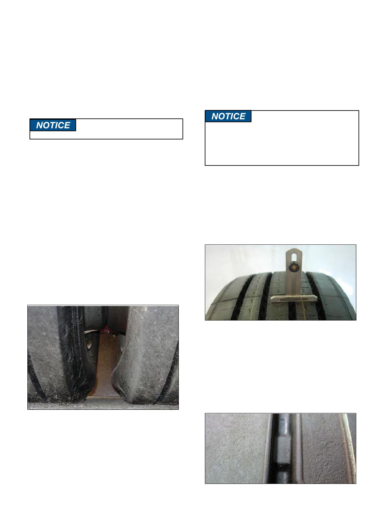
therefore, more frequent checks may be required during
TIRE REPAIRS
cold weather conditions. Avoid outdoor pressure checks
When a tire experiences a tread puncture, it may be
when the temperature is below freezing, as ice can form
safe to return it to service if it is properly repaired. A
in the valve stem and create aslow leak.
tiremust be repaired from theinside so that a careful
As a tire rotates during operation, it will naturally
inspection can be made to the inner liner. The tire
generate internal heat, resulting in an increase of inflation
technician should use a combination plug and patch,
pressure. The pressure foundina“hot” tiremay be as
where the rubber plug seals the damaged area from
much as 10 - 15 psi higher than the inflation pressure
outside contaminants and moisture, and the patch
found before operation. If checking tires after operation,
reinforces the inner liner. Consult a Michelin tire dealer
compare the inflation pressure of all tires to ensure that
for a professional inspection and repair.
they are within 2 - 3 pounds ofeachother across the axle.
Never bleed hot tires, or they
NEVER use a rope type string plug to repair a
will become underinflated.
MICHELIN® tire. A rope plug is considered a
temporary repair and often leaks over time.
It is considered an improper repair and may void
Tire inflation pressures should be maintained across
the MICHELIN® Truck Tire Limited Warranty.
an axle at the same inflation pressure, especially in dual
fitment. Make sure to check both tires in a dual fitment;
pressures should be the same. The maximum allowable
TREAD DEPTH MEASUREMENTS AND
difference between tires across an axle is 5 psi. Use a
WEAR BARS
quality, calibrated tire gauge to check inflation pressures,
Tires should be periodically measured for wear. This
preferably a truck tire pressure gauge with a dual angled
measurement should be taken in several spots across the
head. These gauges work best to check the inner and
tread, and around the circumference. If there is a variance
outer dual wheels. In addition, double seal valve caps and
in tread grooves greater than 2/32” across the face of
quality extension hoses simplify and expedite checking
the tire, consult a Michelin tire dealer for a professional
tire inflation pressures.
inspection.
For example, if the recommended tire pressure across
a rear dual axle is 80 psi, and one tire only has 64 psi, it is
considered to be flat. This tire, as well as the tire in service
next to it, should be removed from service by a tire
technician immediately. A qualified tire technician should
demountthetireto conduct athoroughtire andwheel
inspection before returning them to service.
MICHELIN® tires contain “wear bars” in the tread
grooves of the tire tread, which show up when there is
only 2/32” remaining of tread rubber. When the tread is
wornlevel with the wear bar indicator, the tiremust be
removed from service. Federal law requires that, “any
tire on the front wheels of a bus, truck or truck tractor
shall have a tread groove pattern depth of at least 4/32
of an inch when measured at any point on a major tread
groove. The measurements shall not be made where tie
bars, humps or fillets are located”.
Underinflation in a dual configuration overloads the
properly inflated tire. Both tires must be inspected.
Section Six: MICHELIN® RV Tires
115
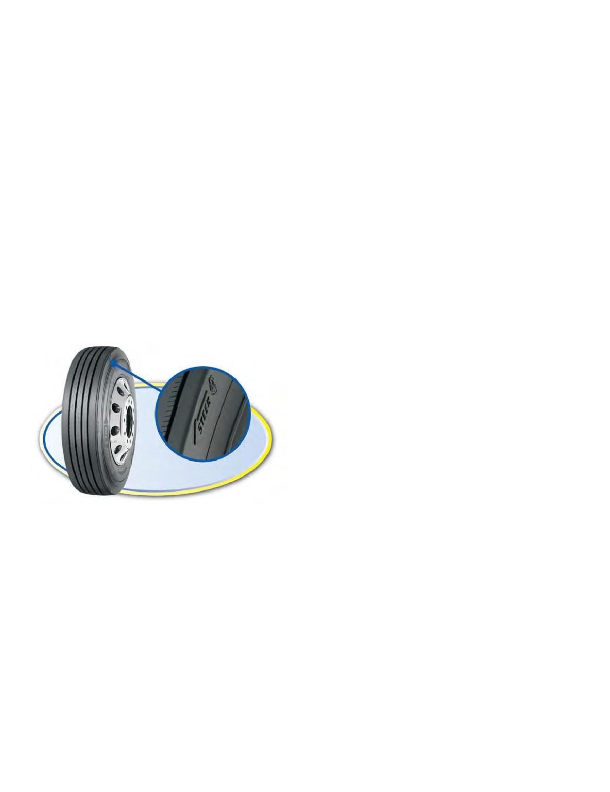
Tires mounted in dual must be matched so that the
TIRE PRESSURE MONITORING SYSTEMS
maximum difference between the diameters of the tires
(TPMS)
does not exceed 1/4” diameter, or a circumferential
There are several manufacturers of Tire Pressure
difference of 3/4”. For tires of the same beaddiameter
Monitoring Systems (TPMS) available for recreational
and size, the maximum allowable difference in tread
vehicle usage. TPMS systems monitor internal tire
depth is 4/32”. When there is a difference in tread wear, fit
pressure levels during vehicle operation; some also
the least worn tire in the outside wheel position. Failure
provide the actual internal tire temperature readings.
to properlymatch dual tires will result in the tire with
Maintaining proper tire inflation will helpmaximize tire
the larger diameter carrying a disproportionate share of
life and fuel efficiency, and may result in a reduction
the load. Mismatched duals can lead to rapid tire wear,
inirregular tire wear and tire costs. If your recreational
uneven tread wear, and possible casing failure.
vehicle is fitted with a TPMS system, consult your Original
Equipment manufacturer or recreational vehicle dealer for
DUAL SPACING
specific service guidelines. While TPMS systems give an
Sufficient space must be maintained between dual tires
early warning of low inflation pressure, they should not be
to allow airflow and to prevent the tires from rubbing
considered as a replacement for manual tire inspections.
against one another. To make sure dual spacing is correct,
simplymeasure from the outside edge of theouter tire
NITROGEN
to the outside edge of the inner tire of the dual assembly,
The earth’s atmosphere is approximately 78% nitrogen,
and cross reference this measurement to the “minimum
along with 21% oxygen, and 1% other gases. Nitrogen is a
dual spacing” found on the tire data page. For additional
dry inert gas that does not retain moisture. While there are
assistance, consult a Michelin tire dealer.
advantages for aircraft and large off-the-road earthmover
tires to use 100% nitrogen systems, it is generally difficult
DIRECTIONAL TIRES
to quantify the advantages for over-the-road highway
operations. The predominant concern for proper tire
inflation is moisture in the compressed air system.
Moisture, when present in the tire, greatly accelerates
the oxidation effects to the tire and the wheel. Using well
maintained inflation equipment (compressor, inflation
lines, and in-line air dryer) will minimize the moisture
content of the compressed air in the tire. Increasing the
nitrogen percentage to 100% with a nitrogen inflation
systemwill not adversely affect the inner liner of the
tires, nor impact tire performance. Regular tire pressure
maintenance remains critical, and tire inflation check
intervals should not be extended due to nitrogen use.
MICHELIN® X® LINE™ ENERGY Z Steer Tire
WORKMANSHIP AND MATERIALS
MICHELIN® truck tires bearing the Michelin name
Several MICHELIN® tires feature directional tread
and complete serial or identification numbers, used
designs to increase tread life and to reduce irregular wear.
in consumer service such as on a recreational vehicle,
Directional tires have arrows molded into the shoulder/
are covered by a limited warranty against defects in
edge of the outer tread rib to indicate the intended
workmanship and materials for the life of the original
direction of rotation. To maximize tire performance,
tread or five years from the date of purchase, whichever
directional tires should be mounted correctly on wheels to
occurs first. At that time, all warranties, expressed or
ensure that the directionality is respected when mounted
implied, expire. Please visit www.michelinrvtires.com
on the recreational vehicle.
under “Reference Materials” for complete details about
Once directional tires are worn greater than 50% of the
the MICHELIN® Truck Tire Warranty, and to complete the
original tread depth, there is generally no negative effect
MICHELIN® Tire Registration. For tires that were fitted
of running them in adirection opposite to the indicated
new on an Original Equipment vehicles (i.e. acquired by
direction of rotation.
the consumer on a new recreational vehicle), for warranty
Operating new directional tires in the opposite direction
purposes, the purchase date of the brand new recreational
of that indicated on the tire will result in a premature
vehicle serves as the date of tire purchase.
onset of irregular wear, an increase in tire noise levels, and
a significant reduction in tread life.
116 Section Six: MICHELIN® RV Tires
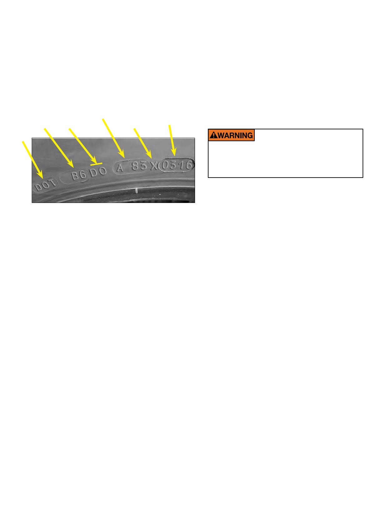
LOCATION OF TIRE IDENTIFICATION CODE
SELECTING ALTERNATIVE TIRE SIZES
The Department of Transportation (DOT) requires
Original Equipment manufacturers carefully select the
that all tires produced for U.S. highways have a Tire
proper tire and wheel for optimum performance and
Identification Number (TIN) imprinted on the tire. This
handling. When replacing tires on a recreational vehicle,
unique identifier is referred to as the DOT code and is
follow theinformation foundon the vehicle placard.
found on the lower sidewall of the tire. The DOT code
Michelin recommends maintaining the original tire size
begins with the letters “DOT”; the last four digits indicate
recommended on the placard, as changing to a different
the week and the year of manufacture. In the example
size may impact the overall vehicle performance. Consult
below, the DOT code ending with “0316” indicates a tire
your recreational vehicle dealer or a Michelin tire dealer
madeinthe3rdweek(Jan)of2016.
before changing tire sizes.
OPTIONAL CODE
MANUFACTURE
DATE
DRIVE AT PROPER SPEEDS
TIRE SIZE
MICHELIN
PLANT
DOT
Do not drive at speeds faster than the speed
ratings for your tires. Never exceed legal speed
limits or speeds reasonable for the driving
conditions.
High speed driving can be dangerous and may damage
your tires. The maximum continuous speed at which
MICHELIN® tires canbe operated is indicatedin the
following data pages. Exceeding this maximum speed will
SERVICE LIFE FOR RECREATIONAL
cause the tire to build up excessive heat that can result in
VEHICLE TIRES
sudden tire destruction, property damage, and personal
MICHELIN® tires are designed to meet the highest
injury. When driving at highway speeds, correct inflation
criteria for quality, performance, and durability. In
pressure is especially important. Michelin does not
addition to natural rubber, MICHELIN® tires contain
endorse exceeding legal speed limits.
more than 200 different raw materials to provide superior
strength and flexibility throughout the life of the tire. Over
LONG TERM STORAGE
time, these components naturally evolve; the evolution
When a tire is fitted to a wheel and put under load,
depends upon many factors such as the environment,
but it is not regularly used, the tire does not have an
storage conditions, and conditions of use (load, speed,
opportunity to “exercise” and will prematurely age.
inflation pressure, and maintenance). Therefore, it is
If a recreational vehicle is not driven regularly, care
impossible to predict when tires should be replaced based
mustbetakentopreservetheremaininglife of the tires.
on their calendar age alone.
Best practices include:
Some recreational vehicle owners may choose to oper-
1. Store the recreational vehicle in a cool, dry,
ate MICHELIN® tires after the tire warranty expires. For
sealed garage, away from electric generators or
consumers who choose to operate tires beyond the tire’s
warranted life, Michelin recommends frequent tire inspec-
transformers. Do not store in an area where welding
tions, especially before long trips. Michelin recommends
is performed, or in a garage that has frequently used
that anytires that are 10 years ormore from the date of
electric motors.
manufacture, including spare tires, be replaced with new
2. Place a barrier between the tire and the storage
tires as a precaution even if such tires appear serviceable
surface. Suitable barriers include plastic, plywood,
and even if they have not reached the legal wear limit.
cardboard, or rubber floor mats.
In addition to frequent tire inspections and proper
3. Before storing the vehicles, thoroughly clean tires
inflation pressure maintenance, Michelin recommends
with soap and water.
regular tire inspections by trained tire technicians.
4. If outdoors, cover tires to block direct sunlight and
Consumers are strongly encouraged to be aware not only
ultraviolet rays.
of their tire visual conditions and inflation pressures,
5. Inflate tires to the maximum inflation pressure
but also of any changes in dynamic performances which
indicated on the sidewall.
could be an indication that the tires need to be removed
6. If long term storage exceeds 3 months, consider
from service. Indications include an increased level of
taking the recreational vehicle for monthly highway
noise or vibration, or an increased frequency in loss
drives(about one hour of operational time). Driving
of inflation pressure (faster than 2 psi per month). For
the vehicle will give the tires an opportunity to
additional assistance, consult a Michelin tire dealer.
generate internal heat which will promote long life.
Section Six: MICHELIN® RV Tires
117
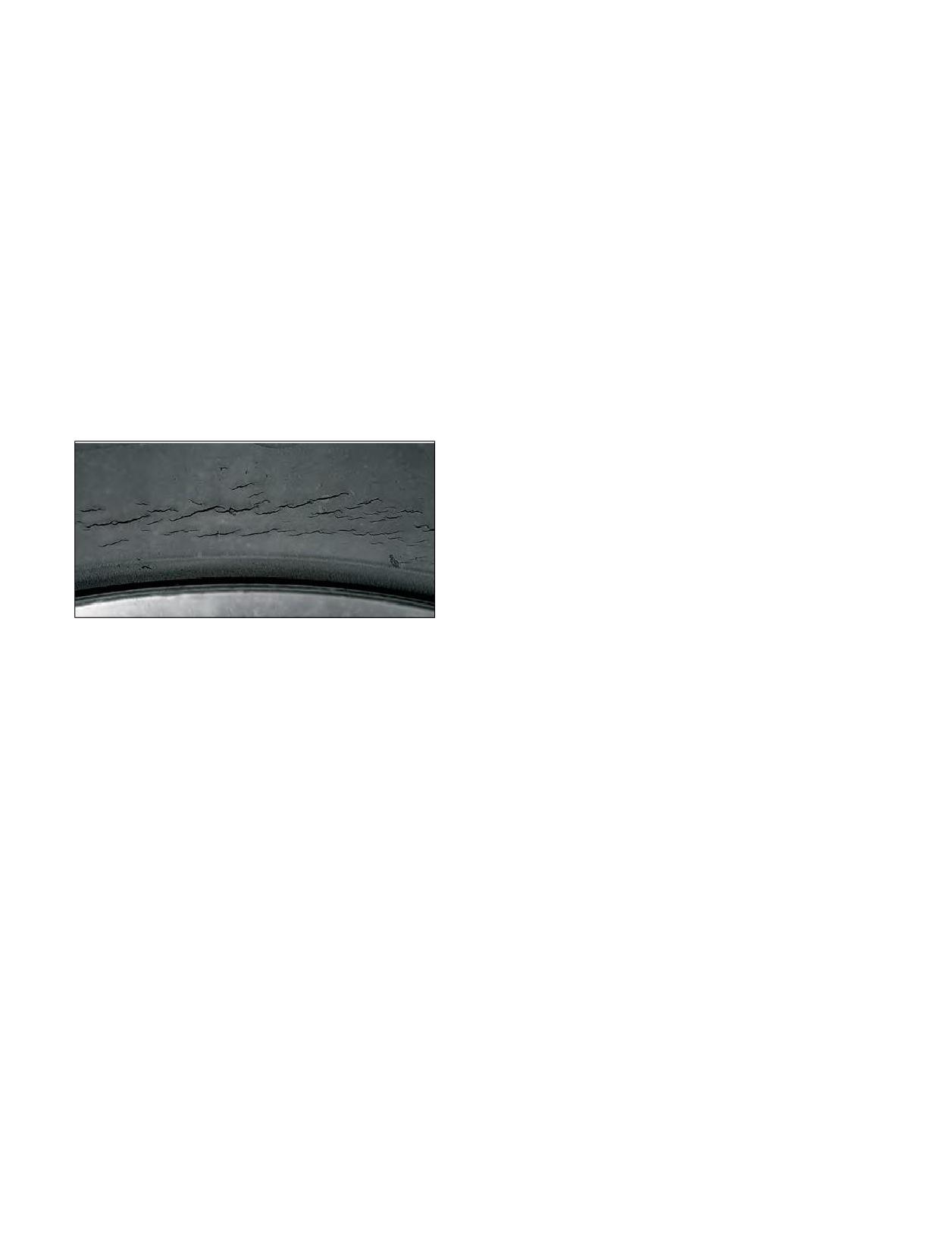
Before removing the vehicle from long term storage,
TIRE ROTATION, BALANCE, ALIGNMENT
thoroughly inspect each tire, and restore all tires to the
AND TIRE WEAR
proper inflation pressure.
When tires are properly mounted and maintained
with the correct inflation pressure, they should wear in
AGING, WEATHER CHECKING, AND
a smooth even wear pattern. To maximize tire wear,
OZONE CRACKING
Michelin recommends the following best practices.
During tire inspections, check the sidewalls for signs of
1. Tire Rotation. MICHELIN® tires should be rotated
aging, referred to as weather checking or ozone cracking.
when necessary. If the tires are wearing evenly, there
Aging appears as tiny cracks in the rubber surface of the
is no need to rotate. If tires begin to show an irregular
sidewall. If the cracks are less than 2/32” deep, the tire is
wear pattern, or if the wear rate on the tires from axle
acceptable to keep in operation; when the cracks extend
to axle or side to side is perceptively different, the tires
deeper than 2/32”, the tire should be inspected by a
should be rotated. There is no restriction on criss-
Michelin tire dealer and possibly replaced.
cross rotation; however, if the vehicle is equipped
with a spare tire/wheel is should be included into
Topromote long life and prevent prematuretire aging:
the rotation pattern. If using directional tires, and
1. Keep tires properly inflated and rotated.
if the tires are less than 50% worn, ensure tires are
2. Keep tires clean, avoiding petroleum products,
mountedto rotate in the proper direction. Once a
alcohol, and silicone.
directional tire has worn more than 50% of its tread, it
is acceptable to rotate into any position.
Considerations about tire rotations include:
• The load carried by a particular tire in a particular
wheelposition varies. Theinside tirein a dual
position carries more load than the outside tire on
the same axle.
• Curbing damage and weather checking often
occurs on the outside sidewall of the outside tire.
• Tires in dual should not differ more than 1/4”
diameter (4/32” tread wear). When there is a
4. Avoid prolonged exposure to high heat, extreme
difference in tread wear, fit the least worn tire in
cold, and ultraviolet rays.
the outside wheel position.
5. Cover the tires when the vehicle is not in use.
• When there is irregular wear, rotate the tires so
6. Follow the recommendations for long term storage
they turn in the opposite direction.
(Page 117).
2. Tire Balance and Runout. Check with
your recreational vehicle dealer for tire balance
PROPER CLEANING OF RV TIRES
recommendations. It is customary to check tire and
Proper cleaning of tires is important to obtain the
wheel assembly balance and runout if there is a ride
maximum years of service. Road oil will cause deterioration
complaint.
of rubber, and dirt buildup will hold contaminants next to
If there is a ride disturbance, validate that tire
the tire. A soft brush and mild car wash soap is the best way
inflation pressures are properly adjusted. If inflation
to clean tires.
pressures are correct, consult your recreational vehicle
If a dressing product is used on a sidewall, use extra
dealer or a Michelin tire dealer for assistance.
care and caution. Tire dressings that contain petroleum
In order to identify the source of the ride
products, alcohol, or silicones may cause premature aging
disturbance, consider the following factors to assist the
and sidewall cracking.
servicing dealer:
In many cases, it is not the dressing product itself that
• Road conditions when the vibration occurs.
can be a problem, but rather, the chemical reaction that
• Vehicle speed and engine rpms when the vibration
the product can have with the antioxidant waxes found
occurs.
in the tire. Heat can add to this negative reaction. When
• Where the vibration seems to be coming from
these same dressing products are applied to a passenger
(front or rear of the vehicle).
car tire that is replaced every three or four years, itis rare
• Frequency of the vibration (Does it phase in/out,
to see a problem. However, since Recreational Vehicle
or is it constant?).
tires usually last much longer, there is more time for a
chemical reaction to occur.
118 Section Six: MICHELIN® RV Tires
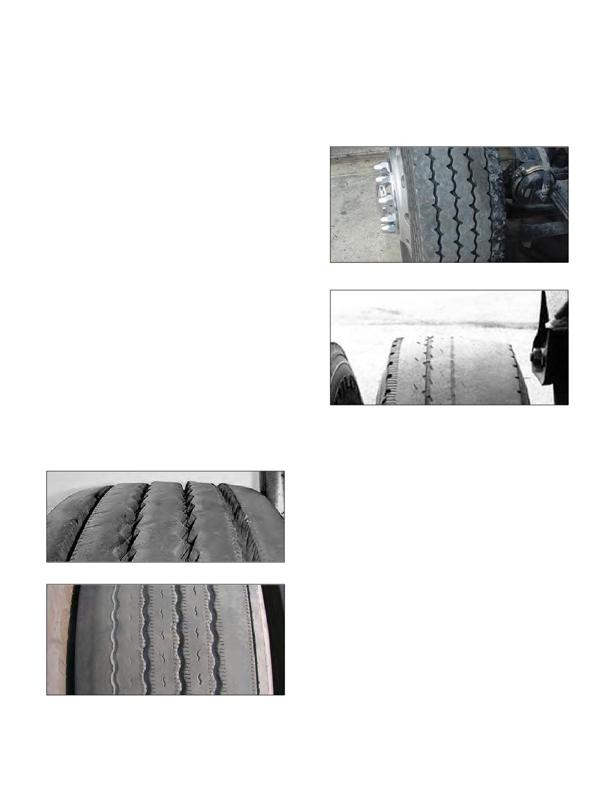
3. Alignment. The purpose of alignment is to
Camber Wear. Also known as edge wear, camber
minimize tire wear and to maximize predictable
wear appears on the inside or outside shoulders of the
vehicle handling and driver control. Toe misalignment
tread. Wear on the inside edge of both tires may be due
is the number one cause of steer tire irregular wear.
to negative camber or toe-out misalignment. If only one
In order to optimize tire wear, consider the following:
tire shows edge wear, check for worn kingpin bushings,
• Tires that are not operated at a normal
bent or worn steering components, or excessive positive
(perpendicular) angle to the road surface typically
camber. For solid beam axles, excessive camber can result
produce uneven tire wear. Tires that are aimed
from axle over-load.
in contrasting directions (because of conflicting
alignment angles) produce unfavorable and
irregular tire wear.
• Tires that are used on highly compliant
suspensions will likely produce irregular tire wear.
• Alignments should be conducted in the
most representative loading condition of the
recreational vehicle, to include cargo load, fuel,
and water.
• Check with your recreational vehicle dealer for
Camber Wear
specific alignment specifications.
Toe Wear. A feathered wear pattern on the front
tires typically indicates misalignment (toe-in or toe-out).
Sometimes, a radial tire will not have this wear pattern
unless the toe condition is severe. Instead of the feathered
edge wear, the tire will be worn on the inside or outside
shoulder, which could be confused with camber wear.
On a three axle recreational vehicle, a skewed rear axle
and/or tag axle could cause feathered edge wear on one
shoulder of one front tire, and feather edge wear on
Camber Wear
the opposite shoulder of the other front tire. In order to
correctly diagnose a tire wear condition, the recreational
COMMON TIRE DAMAGES
vehicle should have an all-wheel alignment.
No tire is indestructible. Certain conditions of use and
abuse can stress a tire beyond its operating limits, causing
it to be prematurely removed from service. Below are 4
tire damages observed on recreational vehicles. This list is
not all inclusive; for additional information, consult your
Michelin tire dealer.
1. Underinflation. Underinflation is often referred
to as a “run-flat” tire and is caused by operating a
Toe Wear
tire at very low or zero pressure. A tire is considered
to be flat when it has operated at less than 80% of
the recommended inflation pressure. When a tire is
underinflated for the load it is carrying, the sidewall
flexes too much and it builds up heat. The tire is
unable to effectively dissipate the heat, and the
heat damages the inner liner, the casing, and the
outer sidewall of the tire. When a tire is operated
underinflated, the tire casing is irreversibly damaged.
If a tire has been operated underinflated, there
Toe Wear
will be physical signs of damage. The inner liner will
show signs of marbling or creasing. The sidewall may
show signs of creasing or flexing damage. In some
cases, if an extremely underinflated tire is operated at
highway speeds, the tire may unseat itself and it will be
Section Six: MICHELIN® RV Tires
119
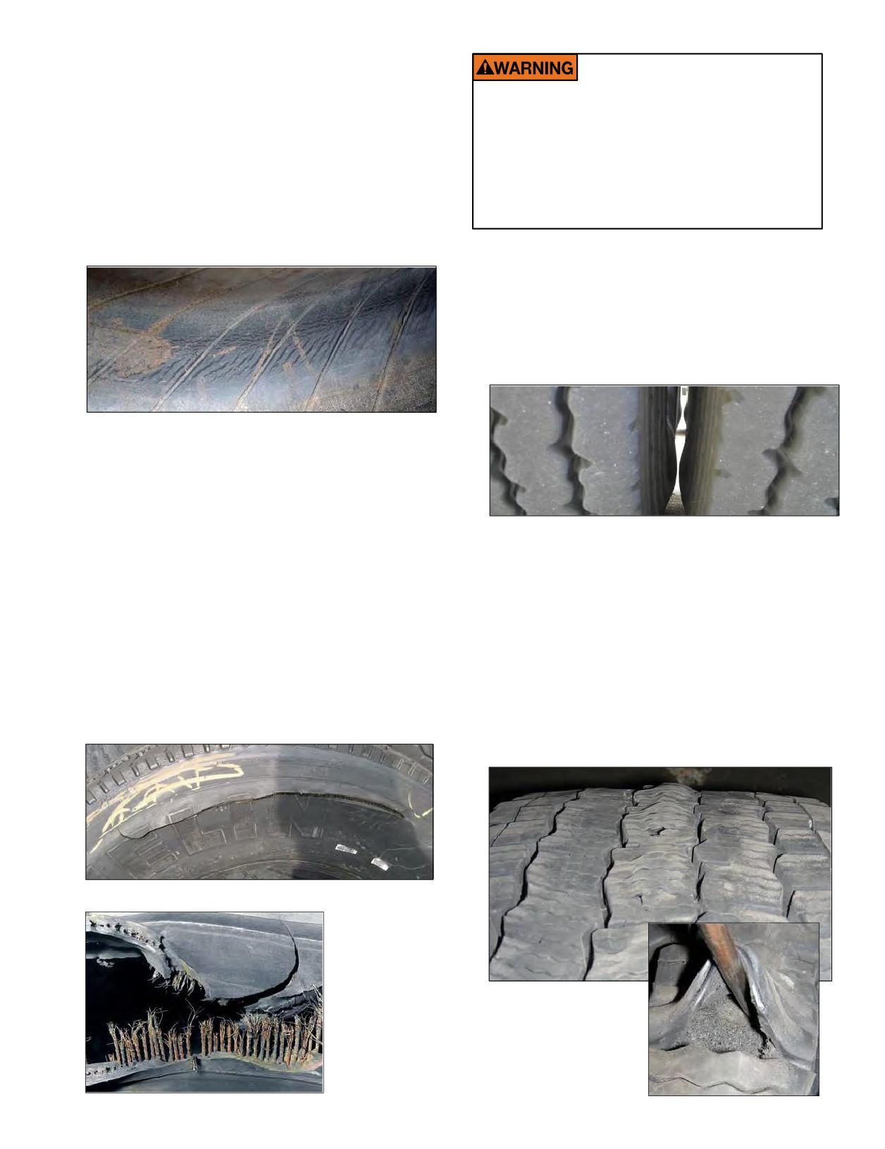
destroyed as the wheel rolls on the uninflated sidewall.
When one tire in a dual configuration comes out of
service due to underinflation, the other tire in the dual
Re-inflation of any type of tire and wheel
configuration should be inspected immediately. If the
assembly that has been operated in a run-flat
or underinflated condition (80% or less of
unserviceable tire was underinflated, the serviceable
recommended operating pressure) can result
dual tire was carrying more of the load for that wheel
in serious injury or death. The tire may be
position. As a result, the properly inflated tire may
damaged on the inside and can explode during
have suffered casing damage. When performing tire
inflation. The wheel may be worn, damaged, or
service on MICHELIN® truck tires with steel casings,
dislodged and can explosively separate.
follow industry safety guidelines. Always use tire safety
cages during the inflation process.
3. Dual Kissing. Dual Kissing damage occurs when
two tires in dual configuration make contact with
each other while in operation. The heat generated by
the friction between the two tires severely weakens
the casing material of both tires. The condition may
be caused by incorrect wheel width, incorrect wheel
offset, or underinflation.
EFFECT: Inner Liner Marbling - Creasing
CAUSE: Underinflation
2. Fatigue Rupture. Fatigue Rupture damage is
sometimes called a “zipper” because of the zipper-
like effect it creates in the steel casing cords of the
EFFECT: Friction Severely Weakens the Casing
damaged tire. When casing cables are repeatedly
CAUSE: Dual Kissing
bent due to overload and/or underinflation, they are
damaged and will eventually break. Since all of the tire
4. Dynamometer Damage. Dynamometer type
cables are exposed to the same amount of stress, many
damageoccursinthecrownareaoftireswhen
will rupture at the same time. This severe rupture is
operated on dynamometers for extended periods of
extremely dangerous and can happen unexpectedly:
time. If a service provider does not adhere to
hours, days or even months after the initial overload
recommended guidelines pertaining to the maximum
happened. Whenever performing tire service on
time and permitted speed for dynamometer testing,
MICHELIN® truck tires with steel casings, follow
irreversible tire damage may later appear on the tread
industry safety guidelines. Always use tire safety cages
surface. For additional information about the
during the inflation process.
maximum time and permitted speeds, consult your
Michelin tire dealer.
Fatigue Rupture or “Zipper”
EFFECT:
Any Damage
That Will Allow
the Casing to
EFFECT:
Oxidize
Internal Deterioration
of the Tread Rubber
CAUSE:
Moisture
CAUSE:
Prolonged Use of
Dynamometer
120 Section Six: MICHELIN® RV Tires
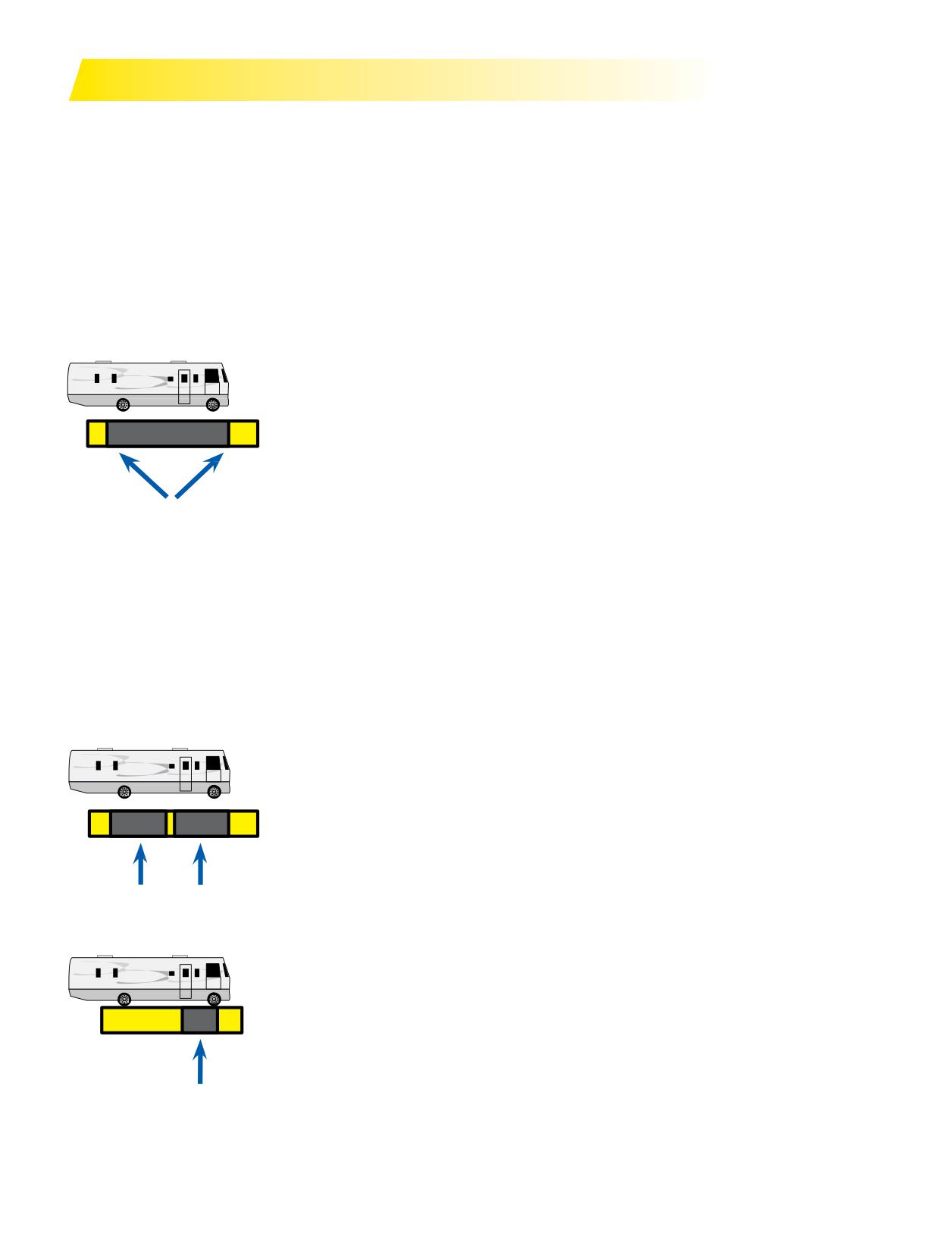
HOW TO WEIGH THE RECREATIONAL VEHICLE
NOTE: Michelin recommends using a professional weighing group or organization to perform the weighing of your Motorhome/
RV. The Recreational Vehicle Safety Foundation (RVSEF) is an organization that performs weighing and other educational
services. They can be contacted at www.rvsafety.com. If you are planning to do your own weighing, you should follow the
procedures below. Michelin recommends checking with the scale operator to make sure there are no concerns on damage to the
scale or to the vehicle if weighing side to side to determine individual wheel position weights.
HOW TO WEIGH THE RV
First, the RV must be weighed fully loaded - that includes passengers, food, clothing, fuel, water, propane, supplies, and
anything else you can think of. Also, any towed vehicle (car, boat, or trailer) or item loaded on brackets on the back of the RV (like
bikes or motorcycles) should be included in the weighing.
THREE DIFFERENT TYPES OF SCALES:
1)
Platform - Platform scales are usually long enough to weigh the entire vehicle at once.
Michelin suggests the following:
a) Pull onto the scale so that only the front axle is on the platform. The rear end of the scale
needstobemidwaybetweenthefrontandrearaxles.Recordtheweight.
b) Pull forward until the full unit is on the scale. Record the weight.
c) Pull forward until only the rear axle is on the platform. The front end of the scale needs to
be midway between the front and rear axles. Record the weight.
SCALE
d) If the RV has a rear tag axle, pull forward so only tag axle is on the scale. Record the weight.
e) To determine individual wheel position weights, repeat steps (a) through (d) with only one
side of the vehicle actually on the scale and the vehicle centered over the side of the scale.
See diagram on next page. Record the weights.
f) Tocalculate the opposite wheel positions’ weights, subtract the weights recordedin step
(e) from the weights recorded in steps (a) through (d). If there is not a towed vehicle, the tag
axle weight derived from (d) will represent the actual weight on the tag axle.
g) If a vehicle is being towed, it should be weighed and combined with the GVW (Gross
Vehicle Weight) to ensure the total weight doesn’t exceed the GCWR (Gross Combined
Weight Rating).
2)
Segmented Platform - Platform scales with segmented sections can provide individual axle
weights and total vehicle weights all at once when the vehicle is positioned properly.
To do this, simply:
a) Position the vehicle on the scales so that each axleis centered asmuch as possible on the
segments, and record the weight.
b) Reposition the vehicle so that only one side is on the scale - centered on the segment as
much as possible.
SCALE
c) Subtract the weighed wheel positions from the total axle weights to determine the
unweighed wheel position weights.
3)
Single Axle - Weighs one axle at a time.
Follow these steps:
a) Drive the front axle onto the scale and stop long enough for the weight to be recorded.
b) Pull vehicle forward until the rear axle is on the scale.
c) For gross vehicle weight, add the two axle weights together.
d) To obtain the individual wheel position weights, repeat this process with only one side of
the RVonthescale.
SCALE
Note: Even though the weight of the total axle is within the axle rating, it may be overloaded
on one side, whichmeans anoverloaded wheel position. That’s why side-to-side weighing is
required.
Section Six: MICHELIN® RV Tires
121
The RV must remain as level as possible on the scale (even when an axle or side isn’t on the scale). Therefore, to
obtain side-to-side weights, there must be enough space on either side of the scale to accommodate the RV being
partially off the scale.
If there is a difference in the weights on one side of the vehicle as compared to the other, it is important to
redistribute the load more evenly to avoid component failure and improve handling. These weights make it possible
to compare against the GAWR (Gross Axle Weight Rating), GVWR (Gross Vehicle Weight Rating), and tire capacities.
They also help determine proper tire pressure.
WEIGHING THE SINGLE AXLE RECREATIONAL VEHICLE
TO OBTAIN INDIVIDUAL AXLE AND GROSS VEHICLE WEIGHTS
STEP 1a
STEP 1b
STEP 1c
STEP 1d
Scale Weight
lbs.
lbs.
lbs.
lbs.
(Step 1a =
(Step 1b =
(Step 1c =
(Step 1d)
Gross Axle Weight)
Gross Vehicle Weight)
Gross Axle Weight)
From
lbs.
lbs.
lbs.
lbs.
Owner’s
Gross Axle
Gross Vehicle
Gross Axle
Vehicle Weight
Manual
Weight Rating
Weight Rating
Weight Rating
(Gross Combined
Weight Rating -
Gross Vehicle Weight)
TO OBTAIN INDIVIDUAL WHEEL POSITION WEIGHTS
STEP 2a
STEP 2b
STEP 2c
One Side
Scale Weight
lbs.
lbs.
lbs.
(Step 2a)
(Step 2b)
(Step 2c)
Calculate Other
lbs.
lbs.
lbs.
Side Weight
(Step 1a-2a)
(Step 1b-2b)
(Step 1c-2c)
lbs.
lbs.
lbs.
Tire Load (lbs.)
(See Note #1)
(See Notes #1 & #2)
Inflation
psi
psi
(See Note #1)
(See Note #1)
NOTES:
1. From the tire manufacturer’s load and infl
tables or the sidewall of the tires mounted on the vehicle.
2. If vehicle has duals, read dual capacity from tire and multiply by 2 to obtain dual assembly load capacity.
122 Section Six: MICHELIN® RV Tires
WEIGHING THE TANDEM AXLE RECREATIONAL VEHICLE
TO OBTAIN INDIVIDUAL AXLE AND GROSS VEHICLE WEIGHTS
STEP 1a
STEP 1b
STEP 1c
STEP 1d
STEP 1e
(calculated)
lbs.
lbs.
lbs.
lbs.
lbs.
Scale
(Step 1a =
(Step 1b =
(Step 1c)
(Step 1d =
Drive Axle
Weight
Gross Axle Weight)
Gross Vehicle Weight)
Gross Axle Weight)
Weight = (1c-1d)
lbs.
lbs.
lbs.
lbs.
From
Gross Axle
Gross Vehicle
Gross Axle
Gross Axle
Owner’s
Manual
Weight Rating
Weight Rating
Weight Rating
Weight Rating
TO OBTAIN INDIVIDUAL WHEEL POSITION WEIGHTS
STEP 2a
STEP 2b
STEP 2c
STEP 2d
(calculated)
One Side
lbs.
lbs.
lbs.
lbs.
Scale Weight
(Step 2a)
(Step 2b)
(Step 2c)
Step 2d: Right Duals = (2b-2c)
lbs.
lbs.
lbs.
lbs.
Calculate Other
Side Weight
(Step 1a-2a)
(Step 1c-2b)
(Step 1d-2c)
Left Duals = (2d)
lbs.
lbs.
lbs.
Tire Load (lbs.)
(See Note #1)
(See Note #1)
(See Notes #1 & #2)
psi
psi
psi
Inflation
(See Note #1)
(See Note #1)
(See Note #1)
NOTES:
1. From the tire manufacturer’s load and infl
tables or the sidewall of the tires mounted on the vehicle.
2. If vehicle has duals, read dual capacity from tire and multiply by 2 to obtain dual assembly load capacity.
THE EFFECT OF TOWED VEHICLES OR TRAILERS
Ifyour RV is towing a vehicle, you need to know the RV’s GCWR (GrossCombinedWeight Rating),the total actual loaded
weight of the RV, plus the total actual loaded weight of the towed vehicle. Even though the GCWR hasmore to do with the
design limits of the drivetrain (engine, transmission, axle, brakes, and bearings), the additional weight can also affect the tires
and the RV’s handling. Also, always remember to consider the tongue weight of the trailer and its effect on handling.
Section Six: MICHELIN® RV Tires
123
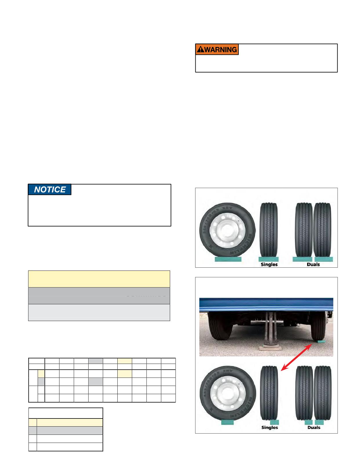
HOW TO USE THE ACTUAL RV WEIGHT
USING BLOCKS TO LEVEL MOTORHOMES
INFORMATION WITH THE TIRE DATA
AND RVS EQUIPPED WITH RADIAL TIRES
LOAD CHART
Let’s consider an RV running on 275/80R22.5
MICHELIN® X® LINE ENERGY Z LRG tires, with actual
Assure that tires are properly supported during
corner weights of 5,400 lbs. on the left front tire, 5,175 lbs.
storage to avoid structural damage to the tire.
on the right front tire, 8,500 lbs. on the left rear duals, and
9,200 lbs. on the right rear duals. For control of the RV, it is
When using blocks to level motorhomes or RVs,
critical that the tire pressures be the same across an axle.
extreme caution must be taken to make sure the tires
Therefore, wemust “overinflate” the right front tire and
are fully supported. The weight on the tire should be
the left rear duals. Checking the load/inflation table below
evenly distributed on the block. And in the case of duals,
shows that a cold tire pressure of 95 psi will support 5,510
it should be evenly distributed on blocks for both tires.
lbs. on a single front tire.
Ifnot, the sidewall cables can become fatigued and
To determine the pressure for the rear duals, again take
damaged, resulting in a sidewall rupture and a complete,
the heaviest position, in this instance the right rear weighs
sudden loss of pressure.
9,200 lbs. The load/inflation table below shows that a cold
Note in the correctmethod, the blocks are wider
pressure of 85 psi will support 9,380 lbs. on 2 dual tires. It
than the tread and longer than the tire’s footprint. This
is important to note that the cold inflation pressure for the
provides maximum support to the tires and assures that
tire must never exceed the maximum inflation rating that is
the load is evenly distributed.
stamped on the wheel.
CORRECT - Evenly supporting the full load.
REMEMBER: For control of the recreational
vehicle, it is critical that the tire inflation
pressures are set to the same inflation pressure
across an axle.
Tofind the proper inflation pressure, refer to the
load and inflation charts in the MICHELIN® RV Tires
(MWL43146) or visit www.michelinrvtires.com. These
charts have been altered for RV usage only.
S = 1 tire on 1 side of single axle
Single Axle
INCORRECT - One tire or only a portion of
one tire is supporting the full load.
D = 2 tires on 1 side of dual axle
Dual Axle
For Tag axle, use applicable
Single or Dual chart
LOAD AND INFLATION TABLE
This chart is for RV wheel end use only.
275/80R22.5 LRG - MICHELIN® X® LINE ENERGY Z
PSI
70
75
80
85
90
95
100
105
110
kPa
480
520
550
590
620
660
690
720
760
S
4500
4725
4940
5155
5370
5510
5780
5980
6175
LBS
D
8190
8600
9080
9380
9770
10140
10520
10880
11350
S
2040
2140
2240
2340
2440
2500
2620
2710
2800
KG
D
3720
3900
4120
4260
4440
4600
4780
4940
5150
MAXIMUM LOAD AND PRESSURE
ON SIDEWALL
S
6175 LBS at 110 PSI
D
5675 LBS at 110 PSI
S
2800 KG at 760 kPa
D
2575 KG at 760 kPa
124 Section Six: MICHELIN® RV Tires