Parker Variable Speed Drive AC30 series. User’s Manual (2017) - page 17
 

  Index      Manuals     Parker Variable Speed Drive AC30 series. User’s Manual (2017)


Search            copyright infringement  


Content      ..     15      16      17      18     ..


Parker Variable Speed Drive AC30 series. User’s Manual (2017) - page 17


Compliance 

C-16


Cable Screening Bracket Kits 


Frame 

Cable Screening Bracket Kit & Contents 


Control Bracket 

System Bracket 

Power Terminal Bracket 

C2 Ferrite Core 

Frame D 

LA501935U001


Frame E


LA501935U002


Frame F


LA501935U003


Frame G 

LA501935U004 


Frame H 

LA501935U005 


Frame J 

LA501935U006 


Frame K 

n/a 


AC30D 

LA501935U007 


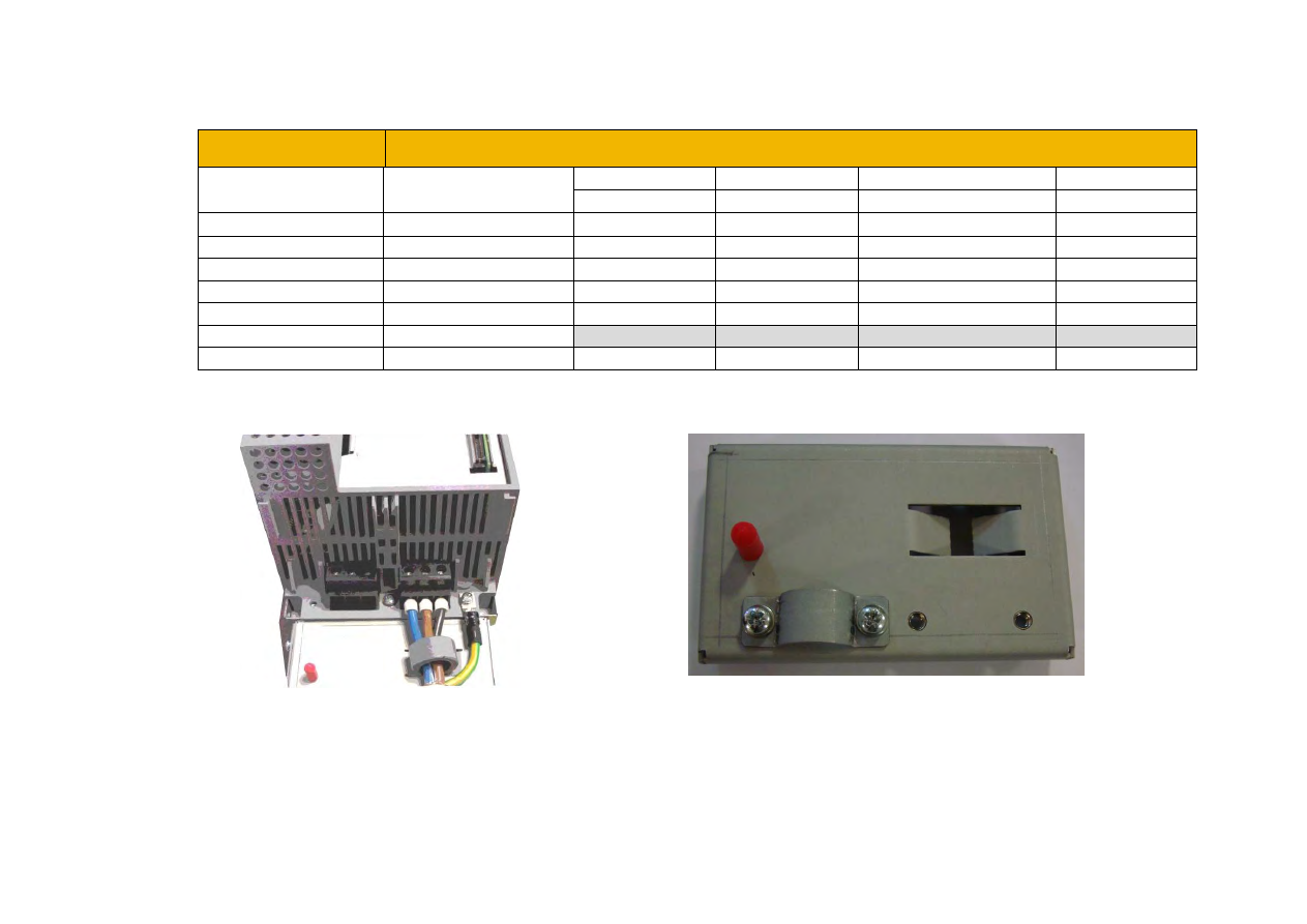
NOTE:  The addition of a cable screening bracket kit to frames D, E and F drive (only) will reduce emissions from Category C3 and C2. 


C-17   

Compliance   


External AC Supply EMC Filter 


   WARNING 

External filters are available for use with TN and IT supplies. When used on a IT supply the filter performance reduces from category C1 

to Category C2. Please check for suitability on following page for External AC Supply (RFI) Filters.  

Do not touch filter terminals or cabling for at least 3 minutes after removing the ac supply. 

Mount the filter as close as possible to the drive. 


External Filters for (Frame D, E, F, H & J) 

 
They are suitable for wall or cubicle mount, but the filter must be fitted with the appropriate gland box when wall mounted. 
 

Filter Description 

Filter Part Number 

Terminal Block 

Earth Terminal 

Dimensions 

Fixing Centres 

Weight 

Frame D & E


500V IT/TN 

CO501894 

10mm

2


M6 Stud 

272 x 74 x 161mm 

258 x 60mm 

2.7kg 

Frame F


500V IT/TN 

CO501895 

50mm

2


M8 Stud 

312 x 93 x 190mm 

298 x 79mm 

3.7kg 

Frame H


500V IT/TN 

CO502672U150 

70mm

2


M10 Stud 

320 x 126 x 212mm 

298 x 112mm 

5.2kg 

Frame J


500V IT/TN 

CO50272U320 

M10 Busbar 

M10 Stud 

268 x 186 x 77mm 

170 x 90mm 

4.4kg 


Compliance 

C-18


Frame D & E Filter Dimensions 


81 

SPECIFICATIONS 


VOLTAGE  500Vac 
FREQUENCY  50/60Hz 
CURRENT  36A @ 40

O

TEMPERATURE - 25 to 100

o

LEAKAGE CURRENT 81mA @ 500V 50Hz 
HUMIDITY 90% RH (NON-CONDENSING) 
VIBRATION 10-200Hz 1.8G 
ELECTRIC STRENGTH 2250Vac/1min. 
POWER DISSIPATION 16W 
MASS 2.7kg 
TERMINALS 10sq mm TERMINAL BLOCK 
EARTH TERMINALS M6 STUD 
FLANGE MOUNTING 4x M6 


C-19   

Compliance   


Frame F  


SPECIFICATIONS 


VOLTAGE  500Vac 
FREQUENCY  50/60Hz 
CURRENT 50A@ 40

O

TEMPERATURE - 25 to 100

o

LEAKAGE CURRENT 114mA @ 500V 50Hz 
HUMIDITY 90% RH (NON-CONDENSING) 
VIBRATION 10-200Hz 1.8G 
ELECTRIC STRENGTH 2500Vac/1min. 
POWER DISSIPATION 16W 
MASS 3.7kg 
TERMINALS 50sq mm TERMINAL BLOCK 
EARTH TERMINALS M8 STUD 
FLANGE MOUNTING 4x M6 


Compliance 

C-20


Frame H 


C-21   

Compliance   


Frame J 


Compliance 

C-22


Internal  Filter Disconnection 


Disconnection of the EMC filter invalidates the CE EMC Declaration, the product becomes a component for incorporation and the 

conformity of the complete equipment or installation becomes the responsibility of the installer. 

 
There are separate disconnects for the internal overvoltage suppressors to earth (identified by the label ‘VDR’) and the internal filter capacitors to 
earth (identified by the label ‘YCAP’). 

DC supplied inverters do not have overvoltage suppressors to earth. 

Frame D 

To access the filter disconnect the top and bottom covers, as these need to be removed, then the Control Module, refer to Chapter 4 for removal 
information. Remove the highlighted screws shown below.  


The screw should only be removed once the supply has been disconnected and the residual energy has 
been discharged.   
 
The product should never be powered or operated without the covers, the EMC filter disconnect will 
become live once the screw is removed.   


After removing the Control Module  
unscrew the two highlighted screws to 
disconnect the EMC filter 

After removing top and bottom covers 
unscrew and remove the Control Module. 
 

Not present on dc 
supplied inverters 


C-23   

Compliance   


Frame E: 


To access the filter disconnect the top and bottom covers, as these need to be removed, refer to Chapter 4 for removal information. Remove the 
highlighted screws shown below. 


The screw should only be removed once the supply has been disconnected and the residual energy has 
been discharged.   
 
The product should never be powered or operated without the covers, the EMC filter disconnect will 
become live once the screw is removed.   


Not present on dc 
supplied inverters 


Compliance 

C-24


Frame F:  

 
To access the filter disconnect the top and bottom covers, as these need to be removed, refer to Chapter 4 for removal information. Remove the  
highlighted screws shown below. 


The screw should only be removed once the supply has been disconnected and the residual energy has been 
discharged.   
 
The product should never be powered or operated without the covers, the EMC filter disconnect will become 
live once the screw is removed.   


Not present on dc 
supplied inverters 


C-25   

Compliance   


Frame G: 

To access the filter disconnects the top and bottom covers will need to be removed, refer to Chapter 4 for removal information. Remove the 
highlighted screws shown below.  It is essential that all three ‘YCAP’ disconnect screws are in place, or all three are removed, do NOT remove 
some of the disconnect screws. 


Top  


Bottom 


The screw should only be removed once the supply has been disconnected and the residual energy has been 
discharged.   
 
The product should never be powered or operated without the covers, the EMC filter disconnect will become 
live once the screw is removed.    

Not present on dc 
supplied inverters 


Compliance 

C-26


Frame H: 

To access the filter disconnects the top and bottom covers will need to be removed, refer to Chapter 4 for removal information. Remove the 
highlighted screws shown below.  It is essential that all three ‘YCAP’ disconnect screws are in place, or all three are removed, do NOT remove 
some of the disconnect screws.  


Top  

Bottom 


The screws should only be removed once the supply has been disconnected and the residual energy has been 
discharged.   


“DANGER” – Risk of electric shock.  Cover and cover screws must remain in place while drive is energised”, 
the EMC filter disconnect will become live once cover and cover screws are removed. 


Not present on dc supplied inverters 
Note:  AC supplied inverters first remove 
control module see page 4-18. 

 
C2 Products - 2 x YCAP Disconnects  
 
C3 Products - 1 x YCAP disconnect 
 
Non-filtered products – no YCAP 
disconnects 
 
1 x VDR Disconnect (bottom edge) 


C-27   

Compliance   


Frame J: 

To access the filter disconnects the top and bottom covers will need to be removed, refer to Chapter 4 for removal information. Remove the 
highlighted screws shown below.  It is essential that both  ‘YCAP’ disconnect screws are in place, or both are removed, do NOT remove only one 
of the disconnect screws.  


The screws should only be removed once the supply has been disconnected and the residual energy has been 
discharged.   
 
“DANGER” – Risk of electric shock.  Cover and cover screws must remain in place while drive is energised”, 
the EMC filter disconnect will become live once cover and cover screws are removed. 

Not present on dc 
supplied inverters 


Compliance 

C-28


Frame H & J 

In order to retain IP20 protection when connecting to the DC Bus terminals, only remove part of the upper terminal cover breakouts (see below), 
or provide suitable external guarding. 


Top Cover End View 


Frame H 

Frame J   


C-29   

Compliance   


Frame K: 

To access the filter disconnect, first remove the VCM, refer to Chapter 4 for removal instructions.  Remove the main cover by unscrewing its 4 
fixings (shown on page 4-2), you can then remove the link connection, as highlighted below.  


Link CN1 Is the Y-CAP disconnect.  


Link CN2 is the VDR disconnect.  


The main cover fixings should only be removed once the supply has been disconnected and the residual 
energy has been discharged.   
 
“DANGER” – Risk of electric shock.  Cover and cover screws must remain in place while drive is energised”, 
the EMC filter disconnect will become live once cover and cover screws are removed. 


CN2 

CN1 

Note:  When links are fitted they should be across pins 

1 and 4 on the connectors, as shown above. 


Compliance 

C-30


Harmonic Information – AC Supplied Inverters 

Supply Harmonic Analysis (Frame D - Normal Duty) 


Assumptions: Rsce = 120 at 400V where Q

1n 

 is the rated rms value of the fundamental voltage of the supply 

transformer. The results conform to IEC61000-3-12:2011. 


Fundamental Voltage (V) 

400 

Drive Type 

Three Phase 

Motor Power 
(kW) 

1.1 

1.5 

2.2 

3.0 

4.0 

5.5 


1.1 

1.5 

2.2 

3.0 

4.0 

5.5 

Typical Motor 
Efficiency % 

83 

83 

83 

83 

83 

83 


83 

83 

83 

83 

83 

83 

Harmonic No. 

RMS Current (A) 

Harmonic No. 

RMS Current (A) 

1.943 

2.653 

3.946 

5.335 

7.078 

9.694   

25 

0.064 

0.085 

0.107 

0.140 

0.184 

0.253 

0.000 

0.000 

0.000 

0.001 

0.001 

0.001   

27 

0.000 

0.000 

0.000 

0.000 

0.000 

0.000 

1.479 

2.037 

2.376 

2.573 

2.852 

3.313   

29 

0.047 

0.067 

0.097 

0.132 

0.175 

0.233 

1.106 

1.537 

1.636 

1.646 

1.673 

1.745   

31 

0.037 

0.051 

0.079 

0.107 

0.142 

0.193 

0.000 

0.000 

0.000 

0.000 

0.000 

0.000   

33 

0.000 

0.000 

0.000 

0.000 

0.000 

0.000 

11 

0.406 

0.584 

0.327 

0.446 

0.594 

0.814   

35 

0.034 

0.046 

0.076 

0.103 

0.135 

0.176 

13 

0.204 

0.291 

0.354 

0.386 

0.445 

0.558   

37 

0.030 

0.042 

0.063 

0.086 

0.114 

0.151 

15 

0.000 

0.000 

0.000 

0.000 

0.000 

0.000   

39 

0.000 

0.000 

0.000 

0.000 

0.000 

0.000 

17 

0.153 

0.205 

0.190 

0.259 

0.345 

0.472   

40 

0.000 

0.000 

0.000 

0.000 

0.000 

0.000 

19 

0.126 

0.176 

0.167 

0.203 

0.257 

0.349   

Total RMS 

Current (A) 

2.73 

3.75 

4.92 

6.19 

7.87 

10.47 

21 

0.000 

0.000 

0.000 

0.000 

0.000 

0.000   

23 

0.065 

0.088 

0.130 

0.178 

0.236 

0.32   

* THD 

(I

) % 

70.2 

70.7 

59.8 

50.8 

43.7 

37.8 


* (Total Harmonic Distortion) 

THD(V) x 100

=

=

Q

Q

h2

1n

h 40

=

h 2

%


C-31   

Compliance   


Supply Harmonic Analysis (Frame E - Normal Duty) 


Assumptions: Rsce = 120 at 400V


where Q

1n 

 is the rated rms value of the fundamental voltage of the supply 

transformer. The results conform to IEC61000-3-12:2011. 


Fundamental Voltage (V) 

400 

Drive Type 

Three Phase 

Motor Power 
(kW) 

7.5 

11 


7.5 

11 

Typical Motor 
Efficiency % 

83 

86 


83 

86 

Harmonic No. 

RMS Current (A) 

Harmonic No. 

RMS Current (A) 

12.801 

18.703 


25 

0.306 

0.484 

0.002 

0.002 


27 

0.000 

0.000 

5.284 

6.467 


29 

0.295 

0.448 

3.010 

3.425 


31 

0.234 

0.370 

0.000 

0.000 


33 

0.000 

0.000 

11 

1.065 

1.571 


35 

0.224 

0.338 

13 

0.769 

1.078 


37 

0.185 

0.290 

15 

0.000 

0.000 


39 

0.000 

0.000 

17 

0.604 

0.909 


40 

0.000 

0.000 

19 

0.433 

0.669 


Total RMS 

Current (A) 

14.27 

20.24 

21 

0.000 

0.000 


23 

0.406 

0.616 


* THD (

I

)% 

44.2 

38.2 


* (Total Harmonic Distortion) 


THD(V) x 100

=

=

Q

Q

h2

1n

h 40

=

h 2

%


Content      ..     15      16      17      18     ..