Parker Variable Speed Drive AC30 series. User’s Manual (2017) - page 15
 

  Index      Manuals     Parker Variable Speed Drive AC30 series. User’s Manual (2017)


Search            copyright infringement  


Content      ..     13      14      15      16     ..


Parker Variable Speed Drive AC30 series. User’s Manual (2017) - page 15


A-21 

Fieldbuses    


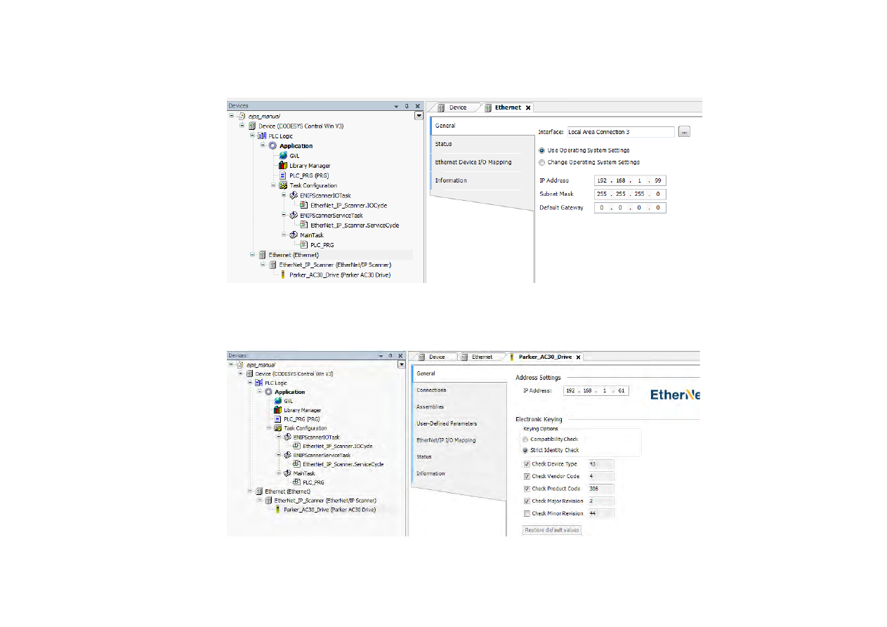
5.  Double-click on 

Ethernet

 and under the 

General

 tab select the required interface. 


6.  Double-click on 

Parker AC30 Drive

 and under the 

General

 tab set the IP address to that of the inverter. 


Fieldbuses  

A-22


7.  Under the 

Connections

 tab edit the connection if necessary.  The input mapping uses a total of 6 bytes (O->T) and the output mapping also 

uses a total of 6 bytes (T->O).  The mapping sizes on the inverter MUST match that on the PLC.  The RPI (Requested Packet Interval) may 
also be changed. 


A-23 

Fieldbuses    

8.  Under the EtherNet/IP IO Mapping tab the mappings can be seen.   

%IB0

 will be the first byte of the 

Status Word

 and 

%IB2

 will be the first byte of the 

Actual Speed Percent 


%QB0

 will be the first byte of the 

Comms Control Word

 and 

%QB2

 will be the first byte of the 

Comms Reference


9.  In the application program the IO mappings can be accessed as variables as shown in this example. 


Fieldbuses  

A-24


EXPLICIT ACCESS OF PARAMETERS 

Explicit access of the AC30 parameters is possible via the vendor specific object.  Details of this are given in the section CIP Objects – Vendor 
Specific Object. 

A parameter value may be read or written via Class 

64h

, Attribute 

5h

.  The instance number is the same as the parameter number (PNO).  The 

supported services are 

Get Attribute Single

 and 

Set Attribute Single

Strings parameters use the SHORT_STRING format – the string is preceded by a single byte that specifies the length of the string. 


Parameter Arrays 

Parameter arrays may be accessed either as a whole or as a single element.   

Using the parameter number (instance number) that represents the whole array with attribute 5h will return or modify the contents of all 
parameters. 

Using the parameter number that represents a single element will return or modify only that element. 

String arrays may not be accessed as a whole array, but may be accessed via each element. 


Using a CoDeSys Based PLC 

CoDeSys based PLCs can access parameters explicitly using the function blocks 

Get_Attribute_Single 

and 

Set_Attribute_Single

 from the 

library 

EtherNetIP Services


LOST COMMUNICATIONS TRIP 

A trip may be issued by the inverter on the loss of all Class1 connections of the EtherNet/IP adapter.  To enable this, set the parameter 

3129 

EtherNet IP Trip

 to 

LOSS OF CONNECTION


and

 set the 

ETHERNET IP BREAK

 bit in the parameter 

0730 ENABLE 33 – 64


A-25 

Fieldbuses    


TROUBLESHOOTING AND TIPS 


The inverter fails to come out of configuration mode 

The input or output mapping tables have invalid parameter mappings.  The parameter 

3130 EtherNet IP State

 will report 

ERROR

.  Check the 

parameter 

3131 EtherNet IP Diag

 to determine which mapping table has the incorrect mapping.  Note the input mapping table may only contain 

read-writable parameters. 


Failure to make a connection 

A connection between scanner and the adapter will not be made if: 


the input and output assembly data sizes of the scanner do not match the input and output mapping data sizes of the inverter 


the Requested Packet Interval (RPI) of the scanner is set to less than 2ms 


Requested Packet Interval (RPI) 

When mapping a large amount of data use an RPI of at least 10ms. 


Fieldbuses  

A-26


CIP OBJECTS 

The following CIP objects are supported: 
01h 

Identity 

02h 

Message Router 

04h 

Assembly 

06h 

Connection Manager 

64h 

Vendor Specific 

F5h 

TCP/IP Interface 

F6h 

Ethernet Link 


Class Attributes 

Each object has the following class attributes. 

Attribute 

Description 

Type 

Access 

Revision 

UINT 

Get 

Maximum Instance 

UINT 

Get 

Number of Instances 

UINT 

Get 

Optional Attribute List 

UINT 

Get 

Optional Service List 

UINT 

Get 

Maximum Class Attribute 

UINT 

Get 

Maximum Instance Attribute 

UINT 

Get 

Supported Service Code 

Service Name 

0Eh 

Get_Attribute_Single 


Identity Object – 01h 

Instance  Attribute 

Description 

Type 

Value 

Access 

Vendor 

UINT 

0004h (Parker Hannifin) 

Get 

Device Type 

UINT 

002Bh (Generic) 

Get 

Product Code 

UINT 

306 

Get 

Product Revision 

UINT 

02C02h (minor/major) 

Get 

Status 

WORD 

Get 

Serial Number 

UDINT 

Last 4 bytes of inverter MAC address 

Get 

Product Name 

SHORT STRING 

“Parker AC30 Drive” 

Get 

Supported Service Code 

Service Name 

01h 

Get_Attribute_All 

05h 

Reset - Type 0 and Type 1 Reset are supported 

1


0Eh 

Get_Attribute_Single 

1. 

Both Type 0 and Type 1 Reset will restart DHCP if enabled. 


A-27 

Fieldbuses    

Message Router Object – 02h 

Instance  Attribute 

Description 

Type 

Value 

Access 

Object List 

Get 

Total connections 

UINT 

Get 

Active connections 

UINT 

Get 

Supported Service Code 

Service Name 

01h 

Get_Attribute_All 

0Eh 

Get_Attribute_Single 


 Assembly Object – 04h 

Instance  Attribute 

Description 

Type 

Value 

Access 

100 

Input 

USINT[500] 

Parameter mapped values 

Get 

150 

Output 

USINT[496] 

Parameter mapped values 

Get/Set 

Supported Service Code 

Service Name 

0Eh 

Get_Attribute_Single 

10h 

Set_Attribute_Single 


Connection manager – 06h 

There are no attributes for the Connection Manager. 


Fieldbuses  

A-28


TCP/IP Interface Object – F5h 

Instance  Attribute 

Description 

Type 

Value 

Access 


Status 

UINT 

0 – Interface Configuration not 
configured 
1 – Interface Configuration comes from 
DHCP 
2 – Interface Configuration comes from 
non-CIP settings 

Get 

Configuration 
capability 

DWORD 

Bit 2 – DHCP capable (1) 
Bit 5 – non-CIP setting capable (1) 

Get 

Configuration control 

DWORD 

-  If DHCP is disabled then writing a 

value of 0 is allowed 

-  If DHCP is enabled then writing a 

value is 2 is allowed 

Get/Set 

Physical Link Object 
Structure of: 

Path Size 

Path 


UINT 
Array of WORD 


20F6h 2401h 

Get 


Interface 
Configuration 
Structure of: 

IP Address 

Network Address 

Gateway Address 

Name Server  

Name Server 2 

Domain Server Size 

Domain Name 


UDINT 
UDINT 
UDINT 
UDINT 
UDINT 
UINT 
STRING 


Inverter IP address 
Inverter network mask 
Inverter gateway address 


Returns the Domain Name if DHCP is 
enabled and the DHCP server has 
provided it. 

Get 

Host Name 
Structure of: 

Size 

Host Name 


UINT 
STRING 

If DHCP is enabled and bound, returns 
the Host Name if the DHCP server has 
provided it, otherwise returns the 
default Host Name derived from the 
AC30 MAC address. 

Get 

13 

Encap TMO 

UINT 

Inactivity TMO seconds. 
On Type 1 Reset this value will revert 
to a value of 120. 

Get/Set 

Supported Service Code 

Service Name 

01h 

Get_Attribute_All 

0Eh 

Get_Attribute_Single 

10h 

Set_Attribute_Single 

A-29 

Fieldbuses    


 Ethernet Link Object – F6h 

Instance  Attribute 

Description 

Type 

Value 

Access 


Interface Speed 

UDINT 

10 or 100 

Get 

Interface Flags 

DWORD 

Link status 

Get 

Physical address 

USINT[6] 

MAC address 

Get 

10 

Interface label 

SHORT STRING 

“Port 1” or “Port 2” 

Get 

11 

Interface capability 
Structure of: 

Capability bits 

Speed/duplex array 

count  


DWORD 
USINT 


Auto-negotiation and MDIX supported (6) 

Get 

Supported Service Code 

Service Name 

01h 

Get_Attribute_All 

0Eh 

Get_Attribute_Single 


Vendor Specific Object – 64h 


The vendor specific object allows explicit access to AC30 parameters, including string parameters but excluding string arrays. 


Instance  Attribute 

Description 

Type 

Access 

PNO 

Parameter Name 

SHORT STRING 

Get 

CIP data type 

1


USINT 

Get 

Number of parameter 
elements 

2


USINT 

Get 

Parameter qualifier 
Bit 0: Gettable 
Bit 1: Settable 

BYTE 

Get 

Parameter value 

Depends on parameter 

Get/Set 

Parameter min value 

Depends on parameter 

Get 

Parameter max value 

Depends on parameter 

Get 

Supported Service Code 

Service Name 

01h 

Get_Attribute_All 

0Eh 

Get_Attribute_Single 

1. 

Equivalent CIP data types – Volume 1 CIP Specification, Chapter 5A 14.2.1.2  

2. 

For a standard parameter the number of elements will be 1, for a parameter array it will be the number elements in the array, and for a string parameter it will be the maximum 
number of characters. 


Fieldbuses  

A-30


PARAMETER SUMMARY 

The following parameters are relevant to the EtherNet/IP adapter. 

Parameter Name 

No. 

Path 

Default 

Range 


Writable 

EtherNet IP Enable 

3128 

Setup::Communications::Base EtherNet IP 
Parameters::Base Comms::EtherNet IP Adapter 

FALSE 

FALSE 

TRUE 


CONFIG 


EtherNet/IP adapter parameter. 

Enables the built-in EtherNet/IP adapter. 

EtherNet IP Trip 

3129 

Setup::Communications::Base EtherNet IP 
Parameters::Base Comms::EtherNet IP Adapter 

LOSS OF CONNECTION 

0: DISABLED 

1: LOSS OF CONNECTION 


CONFIG 


EtherNet/IP adapter parameter. 

Enables the EtherNet/IP trip on loss of connection. 

Enumerated values: 

0: DISABLED   


- the trip is disabled 

1: LOSS OF CONNECTION 

- the inverter will trip on the loss of all Class 1 connections


EtherNet IP State 

3130 

Monitor::Communications::Base EtherNet IP  

Parameters::Base Comms::EtherNet IP Adapter 

SETUP 

0: SETUP 

1: NW_INIT 

2: WAITING TO CONNECT 

3: CONNECTION IDLE 

4: CONNECTION ACTIVE 

5: ERROR 

6, 7: 

Reserved


8: NONE 


NEVER 


EtherNet/IP adapter parameter. 

Diagnostic indicating the state of the EtherNet/IP adapter. 

Enumerated values: 

0: SETUP 


- EtherNet/IP adapter enabled – the inverter is in the configuration state 

1: NW_INIT 


- network initialization 

2: WAITING TO CONNECT 

- waiting for a Class 1 connection 

3: CONNECTION IDLE   

- Class 1 connection made with scanner in Idle mode 

4: CONNECTION ACTIVE 

- Class 1 connection made with scanner in Run mode 

5: ERROR 


- configuration error 

8: NONE 


- EtherNet/IP adapter disabled


A-31 

Fieldbuses    

Parameter Name 

No. 

Path 

Default 

Range 


Writable 

EtherNet IP Diag 

3131 

Monitor::Communications::Base EtherNet IP  

Parameters::Base Comms::EtherNet IP Adapter 

NONE 

0: NONE 

1: INPUT MAPPING FAILED 

2: OUTPUT MAPPING FAILED 


NEVER 


EtherNet/IP adapter parameter. 

Diagnostic indicating if there is a configuration error. 

Enumerated Values: 

0: NONE 


- no configuration error 

1: INPUT MAPPING FAILED 

- invalid input mapping 

2: OUTPUT MAPPING FAILED  - invalid output mapping


Input Mapping 

3000 

Setup::Communications::Base EtherNet IP 
Parameters::Base Comms::Fieldbus Mapping 

0627  

0681 

0000 

… 

0000 

Maximum parameter number 


NEVER 


EtherNet/IP adapter parameter. 

List of PNOs for the built-in fieldbus input parameter mapping. 

Output Mapping 

3064 

Setup::Communications::Base EtherNet IP 
Parameters::Base Comms::Fieldbus Mapping 

0661 

0395 

0000 

… 

0000 

Maximum parameter number 


NEVER 


EtherNet/IP adapter parameter. 

List of PNOs for the built-in fieldbus output parameter mapping.


B-1 

Sequencing Logic    

Appendix B: 

Sequencing Logic 

Drive State Machine 

DS402 

The sequencing of the inverter is based on the DS402 / DriveCOM / IEC 61800-7 standard as used by most industrial fieldbusses. This allows it 

to be easily controlled and monitored by a PLC using the standards’ Control Word and Status Word.  


SEQUENCING STATE 

The sequencing state of the unit is indicated by an enumerated value given by the 

0678 Sequencing State

 parameter. 


Value 

DS402 Sequencing State 

Description 

NOT READY TO SWITCH ON 

Not ready to switch on. The drive is initialising or being configured. 

SWITCH ON DISABLED 

The Drive will not accept a switch on command  

READY TO SWITCH ON 

The Drive will accept a switch on command. 


SWITCHED ON 

The Drive will accept an Operation Enable (Run or Jog) command. 
- Power stage of the Drive is ready to operate. 

- Voltage has not yet been applied to the motor terminals. 

OPERATIONAL ENABLED 

Normal operational state of the drive. This state includes Running, Jogging, 

Stopping (Disabling Operation) and Shutting Down (Switching Off).  
- Voltage applied to the motor terminals. 

QUICKSTOP ACTIVE 

Emergency stop (Fast stop) is active 

FAULT REACTION ACTIVE  

The Drive is processing a trip event 

FAULTED 

The Drive is tripped awaiting trip reset 

Sequencing Logic  

B-2


SEQUENCING DIAGRAM 


NOT READY TO SWITCH ON

SWITCH ON DISABLED

SWITCHED ON

READY TO SWITCH ON

OPERATION ENABLED

No Power

FAULT REACTION ACTIVE

FAULTED

QUICKSTOP ACTIVE

From all states


2

3

4

5

6

7

8

1

10

11

12

13

14

15

0

9


B-3 

Sequencing Logic    

The OPERATION ENABLED state is the normal operation state of the Drive. In this state the Reference Ramp is active, generating a Speed 

Demand. Sub-states and allowed transitions are shown below. Note – the RUNNING sub-state also includes JOGGING.  

 OPERATION ENABLED

 OPERATION ENABLED

RUNNING

STOPPING

(DISABLE OPERATION)

SHUTTING DOWN

(SWITCH OFF)

4

8

9

11

5


STATE TRANSITIONS 


State transitions are caused by internal events in the Drive or external commands via the Control Word. The transition numbers below relate to 

those on the Sequence Diagram. 

Transition 0: No Power to NOT READY TO SWITCH ON 


Power has been applied to the control electronics of the drive. 

Sequencing Logic  

B-4


Transition 1: NOT READY TO SWITCH ON to SWITCH ON DISABLED 


Automatic transition when initialisation has been completed and application has been loaded. 

Transition 2: SWITCH ON DISABLED to READY TO SWITCH ON 


Shutdown command received from control device or local signal. 

Transition 3: READY TO SWITCH ON to SWITCHED ON 


Switch On command received from control device or local signal. 

Transition 4: SWITCHED ON to OPERATION ENABLED 


Enable Operation (Run Forward, Run Reverse or Jog) command received from control device or local signal. 

Transition 5: OPERATION ENABLED to SWITCHED ON 


Disable Operation (Stop) command received from control device or local signal and Disabling (Stopping) function completed. 

Transition 6: SWITCHED ON to READY TO SWITCH ON 


Shutdown command received from control device or local signal. 

Transition 7: READY TO SWITCH ON to SWITCH ON DISABLED 


Quick Stop or Disable Voltage command received from control device or local signal. 

Transition 8: OPERATION ENABLED to READY TO SWITCH ON 


Shutdown command received from control device or local signal and Shutdown function completed. 

Transition 9: OPERATION ENABLED to SWITCH ON DISABLED 


Disable Voltage command received from control device or local signal. 

Transition 10: SWITCHED ON to SWITCH ON DISABLED 


Disable Voltage or Quick Stop command received from control device or local signal. 

Transition 11: OPERATION ENABLED to QUICKSTOP ACTIVE 


Quick Stop command received from control device or local signal. 

Transition 12: OPERATION ENABLED to QUICKSTOP ACTIVE 


Automatic transition when the Quick Stop function is completed or Disable Voltage command received. 

Transition 13: any state to FAULT REACTION ACTIVE 


Fault (Trip) occurred. 

Transition 14: FAULT REACTION ACTIVE to FAULT 


Automatic transition when Fault Reaction function completed or Disable Voltage command received. 

Transition 15: FAULT to SWITCH ON DISABLED 


Fault Reset command received from control device or local signal and there are no active faults. 


B-5 

Sequencing Logic    

CONTROL WORD 

The commands that request a change in sequencer state are received via the Control Word. The current value is given by 

0644 Control Word

This is a read-only parameter which is updated from a source depending on the selected sequencing control channel. The sources available are 

COMMS, APP and LOCAL. 


If COMMS is selected, the value will be taken from 

0627 Comms Control Word

. This will normally be written to over either the Fieldbus interface 

or built-in Ethernet Modbus TCP. The Not Quickstop, Enable Voltage and Switch On bits are ANDed with 

0610 App Control Word. 

The External 

Fault is ORed with the 

0610 App Control Word

.  


If APP is selected, the value will be taken from 

0610 App Control Word

. This will normally be written to by the loaded application which is 

responsible for routing the control signals from Digital Input terminals. 


If LOCAL is selected, the value will be written to by the GKP with the Not Quickstop, Enable Voltage, External Fault and Switch On bits from 

0610 

App Control Word.


Bit 

Name 

Description 

Switch On 

OFF1    = 1 to switch on 

Enable Voltage 

OFF2    = 0 to coast stop 

Not Quickstop 

OFF3    = 0 to emergency stop 

Enable Operation 

1 = Run 

Enable Ramp Output 

=0 to set ramp output to zero   

Not implemented, See note below


Enable Ramp 

=0 to hold ramp  


Not implemented, See note below


Enable Ramp Input 

=0 to set ramp input to zero 


Not implemented, See note below


Reset Fault 

Reset trips on 0 to 1 transition 

External Fault 

1 = External (Application) trip active 


unused 

10 

Use Comms Control 

1 = Use 

0627 Comms Control Word

 as the Control Word source for sequencing 

11 

Use Comms Reference 

1 = Use 

0681 Comms Reference

 as the Reference source 

12 

Use Jog Reference 

1 = Run using 

0501 Jog Setpoint

 when Enable Operation = 1 

13 

Reverse Direction 

1 = Run in reverse direction when Enable Operation = 1 

14 

Auto Initialise 

1 = Allow SWITCH ON DISABLED to READY TO SWITCH ON transition regardless of bit 0 (Switch On) 

15 

Event Triggered OP 

1 = Rising-edge of Enable Operation required for SWITCHED ON to OPERATION ENABLED transition 

Setting “Event Triggered OP” to 0 could cause the motor to start unexpectedly. 


Note – bits 4, 5, 6 must be set (= 1) to allow the ramp control feature to be added in the future. 


Content      ..     13      14      15      16     ..