XCMG XE210C Hydraulic Excavator. Operating & Maintenance Manual (2011) - page 7
r
Operating and Maintenance Manual 127
are found near to the connections of pipes, the air leak may occur to these connections.
c)
Check of refrigerant amount: after running the engine at 1500r/min for 1 to 3 minutes, check the
amount of refrigerant through a sight glass on the liquid reservoir.
d)
Check of condenser: if the blade of condenser is blocked by dirt or bugs, its cooling effects will be
reduced. Therefore, keep them always clean.
e)
Check of compressor: after using the air conditioner 5 to 10 minutes, touch the pipes on high- and
low-pressure sides. If they are normal, the pipe on high-pressure side shall be hot, while that on
low-pressure side shall be cold.
f)
Check the mounting bolt for loosening: ensure the mounting bolt and other mounting or tightening
bolts of compressor are well tightened.
g)
Check of belt and adjustment of tension: Check the compressor and fan belt for wears visually.
According to the above figure, check and adjust the tension of belt. The pressure of fan and
compressor belt: ca.98N, deflection: 7 to 10mm.
z
Check the tightening torques of bolt and nut.
Check the tightening torques of bolt and nut every 250 hours.
After the first 50 hour breaking-in period of machine, check the tightness of bolt and nut, and then
check it once every 250 hours. If loose, tighten the bolt up to the torque shown in Tightening of Bolt.
In case of replacement, replace it with the same or higher-class bolt and nut. For the bolt and nut
outside Tightening of Bolt, refer to “Tightening Torques”.
Important: check or tighten the bolt and nut with a torque wrench.
a)
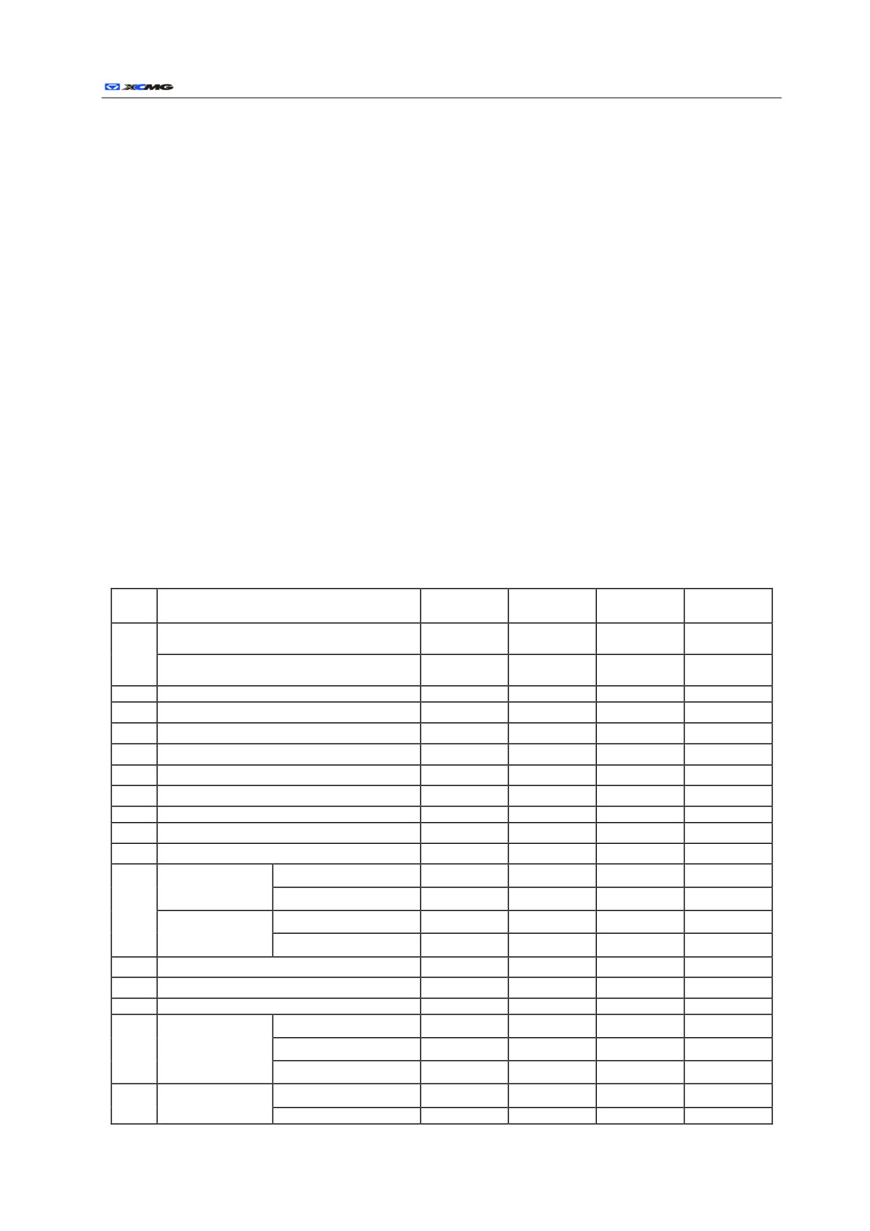
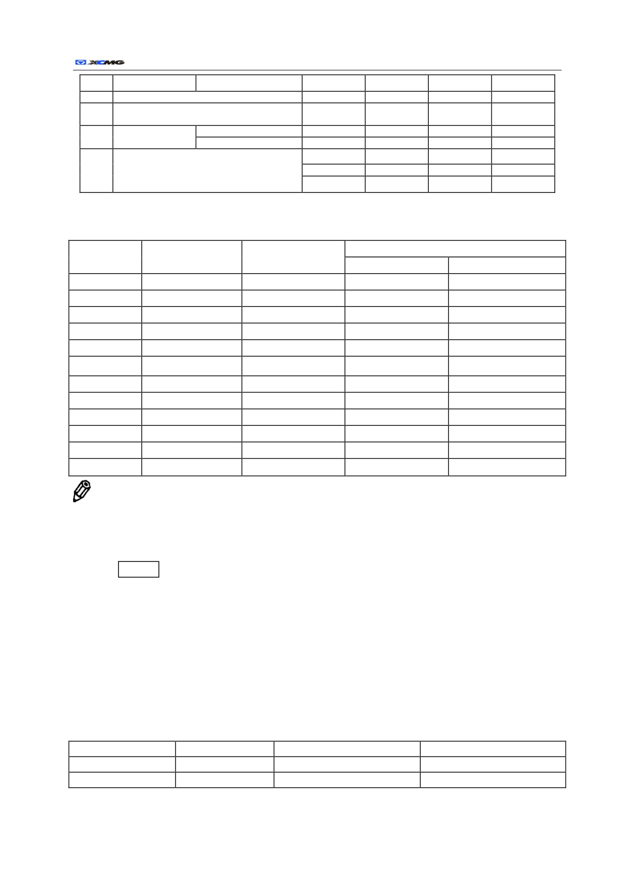
Tightening Torques of Bolt
Table 2-4 Tightening of Bolt
Bolt diameter
Sleeve size
Torque
S/N
Item
Qty
mm
mm
Nm
Fixing bolt of engine vibration isolating
18
2
27
410
rubber gasket (pump side)
1
Fixing nut of engine vibration isolating rubber
12
4
18
120
gasket (fan side)
2
Fixing bolt and nut of engine bearer
10
14
16
70
3
Fixing bolt of hydraulic oil tank
18
4
27
300
4
Fixing bolt of fuel tank
16
4
24
210
5
Fixing bolt of hydraulic pump
20
4
30
600
6
Fixing bolt of multi-way valve
12
3
18
120
7
Fixing bolt of multi-way valve holder
16
4
24
210
8
Fixing bolt of rotation gear
20
13
30
600
9
Fixing nut of battery
10
2
16
50
10
Fixing nut of cab
16
4
24
210
Fixing bolt of
XE210C
22
32
34
800
rotary bearing
XE230C/XE260C
22
36
34
800
(upper car)
11
Fixing bolt of
XE210C
20
36
30
600
rotary bearing
XE230C/XE260C
(lower car)
22
36
34
800
12
Fixing bolt of traction unit
16
60
24
300
13
Fixing bolt of driving wheel
16
44
24
300
14
Fixing bolt of bearing roller
16
16
24
300
XE210C
410
18
56~64
27
Fixing bolt of
15
XE230C
18
72
27
410
bearing wheel
XE260C
410
18
72
27
XE210C
410
Fixing bolt of
18
368~376
27
16
track plate
XE230C
18
376
27
410
r
Operating and Maintenance Manual 128
XE260C
18
408
27
400
17
Fixing bolt of rail clamp
16
8
24
210
Supporting bolt and nut of working device pin
18
16
-
24
280
shaft
Counterweight
XE210C
36
4
55
3000
19
mounting bolt
XE230C/XE260C
36
4
55
3000
8
-
13
22
Low-pressure pipe adapter and T-shape bolt
20
5
-
8
9
clip
6
-
10
9
b)
Tightening Torques
Table 2-5 Tightening Torques
Bolt
Size of socket wrench
Size of inner hexagonal
Torque Nm
specification
mm
wrench mm
10.9 class
8.8 class
M8
13
6
30
20
M1O
16
8
70
50
M12
18
10
120
90
M14
21
12
195
140
M16
24
14
300
210
M18
27
410
300
M20
30
17
600
400
M22
34
800
550
M24
36
19
1000
700
M27
41
1500
1050
M30
46
22
1850
1450
M36
55
27
3000
2450
Note: the desired tightening torque is expressed in Nm. For example, in case of tightening the bolt or nut
with a 1m long wrench, turn the tail end of wrench by a force of 120N, and create the following torques:
1m X120 N=120 Nm
In case of creating the same torque with a 0.25m wrench:
0.25mh
=120Nm
The desired force shall be:
120 /0.25=480 N
z
Maintenance of hammer crusher
The operation of hydraulic hammer crusher will accelerate the pollution and deterioration of hydraulic oil.
Therefore, in comparison with the machine with a bucket, require to replace the hydraulic oil and hydraulic
oil tank filter frequently, otherwise the hammer crusher, hydraulic oil pump and other components of
hydraulic system may be damaged, and adopt the following recommended replacement intervals.
Table 2-6 Replacement Intervals (Hours)
Accessory
Utilizing rate
hydraulic oil
Filter element
Bucket
100%
2000
500
Hammer crusher
100%
600
100
z
Maintenance under special environment conditions

r
Operating and Maintenance Manual 129
Table 2-7 Maintenance under Special Environment Conditions
Operating
Maintenance cautions
conditions
Pre-operation: check if the screw plug and all the drain plugs are tightened.
Mud field, rainy or
After-operation: clean the machine, and check if there are broken, damaged, loose or missed nut and
snowy
bolt, and lubricate all the required parts immediately.
Pre-operation: check if the screw plug and all the drain plugs are tightened.
Seaside
After-operation: clean the machine thoroughly with clean water to remove the salt content, and maintain
the electric appliances frequently to avoid their corrosion.
Air filter: clean the filter elements at regular service intervals.
Radiator: clean the mesh enclosure of oil cooler to avoid the blockage of radiator core.
Dusty air
Fuel system: clean the filter elements and sieve at regular short service intervals.
Electric appliances: clean them at regular intervals, especially the terminals of AC generator and starting
motor.
Fuel: adopt the appropriate low-temperature high-quality fuel.
Lubricant: adopt the high-quality low-viscosity hydraulic oil and engine oil.
Engine coolant: be sure to adopt the anti-freezing agent.
Frosty weather
Battery: charge the battery up at short regular intervals. In case of not charging the battery up, the
electrolyte may be frozen.
Crawler: keep the crawler clean, and park the machine on the hard ground to avoid freezing the crawler
on the ground.
Crawler: careful operation. Check if there are broken, damaged or missed bolt and nut frequently, and
loosen the crawler a little looser than usual.
Stony ground
Working device: in case of digging the stony ground, the standard accessories may be damaged, adopt
the front reinforced bucket or heavy-duty bucket.
Falling rocks
Cab: if necessary, install the cab roof support to avoid the damages of falling rocks to the machine.
z
Maintenance of engine
―See “Operating Instructions of Engine” in details.
z
Maintenance of air conditioner
―See “Operating Instructions of Air Conditioner” in details.
r
Operating and Maintenance Manual 130
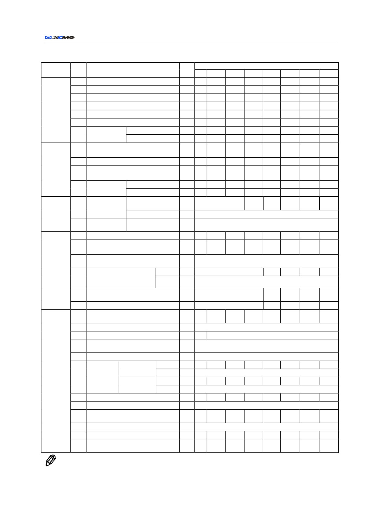
List of Maintenance Periods
Table 2-8 List of Maintenance Periods
Intervals (hours)
Item
S/N
Maintenance point
Qty
8
50
100
250
500
1000
1500
2000
1
Check the level of hydraulic oil.
1
√
2
Drain the oil reserve of oil tank.
1
√
3
Replace the hydraulic oil.
√
Hydraulic
4
Replace oil suction filter
1
√
system
5
Replacement of oil tank filter
1
√
6
Replacement of pilot oil filter
1
√
Check of hose
Oil leak
√
7
and pipe
Crack or bend, etc
√
Drain the dirt reserve tank of fuel
1
1
√
tank
2
Check of water separator
1
√
Fuel
Replacement of fuel filter
(second
system
3
2
√
class)
Check of fuel
Leak or crack
√
4
hose
Crack or bend, etc
√
Or when the
Outer element
Clean
1
√
Air
1
indicator goes on
of air filter
filtering
Replace
1
Clean six times or after one year
system
Inner element
2
Replace
1
When replacing the outer filter elements
of air filter
1
Check of coolant level
1
√
Check or adjustment of fan belt
2
1
√
tension
Replacement of coolant (anti-freeze
3
Twice per year
fluid)
Cooling
Cleaning of radiator and
Inner
1
If required
√
system
4
oil cooler core or
Outer
1
When replacing the cooling water
intercooler
Cleaning of front mesh enclosure of
5
1
If required
√
oil cooler
6
Cleaning of air conditioner condenser
1
If required
√
Check the bucket teeth for wears and
1
√
loosening.
2
Adjustment of bucket connection
1
If required
3
Check and replacement of safety belt
1
√
Every three years (replacement)
Check the level of front window glass
4
1
If required
washing liquid.
5
Check of crawler sag
2
If required
Recirculation
Clean
1
√
Check of
air
air filter
Replace
1
After at least six cleanings
Others
6
conditioner
Fresh
air
Clean
1
√
filter
filter
Replace
1
After at least six cleanings
7
Check of air conditioner
√
8
Fastening of cylinder head bolt
If required
Check and adjustment of valve
9
√
clearance
10
Check of fuel injection timing
If required
11
Check of starter and AC generator
√
Check of bolt and nut tightening
12
ƾ
√
torque
Note: ƾ Maintenance is required only for the first check.
r
Operating and Maintenance Manual 131
Trouble shooting
z
Correct procedures of maintenance and check
In order to maintain and repair the machine correctly, follow the correct maintenance and check
procedures described in this manual.
a)
Check the machine before starting it every day.
1)
Check the controller and instruments.
2)
Check the levels of coolant, fuel and hydraulic oil.
3)
Check the hoses and pipes for leaks, twists, wears or damages.
4)
Make a patrol inspection of common conditions, noises or heat around the machine.
5)
Check the part for loosening or missing.
6)
If anything wrong with the machine, repair it before the operation, or contact with your assigned
dealer.
Important: 1) Adopt the correct oil products, grease and anti-freeze fluid. 2) Any use of
incorrect oil product, grease or sterling part will lead to the loss of product warranty. 3) Don’t
adjust the engine speed limiter or hydraulic system safety valve. 4) Avoid any contact of electric
component with water and steam. 5) Don’t disassemble the main controller, sensor or other
electric components.
b)
Check the hour meter frequently:
1)
Determine the time of machine check and maintenance according to the operating hours shown by the
engine working hour meter.
2)
The intervals shown in List of Maintenance Periods are determined as per the normal operation, and
maintain the machine in shorter interval in case of running the machine under the bad conditions.
3)
Make a periodic check and adjustment of lubrication or maintenance as per the readings of periodic
maintenance meter on the inner side of tool box cover.
4)
When the hours of hour meter reach the replacement time of recommended lubricant and filter
element, or during the periodic check every day or every month, replace the lubricant and filter
element.
c)
Adopt the correct oil products, lubricant and anti-freeze fluid.
Important: adopt the correct oil products, grease and anti-freeze fluid always, otherwise the
machine will be damaged and the warranty of this machine will be lost.
z
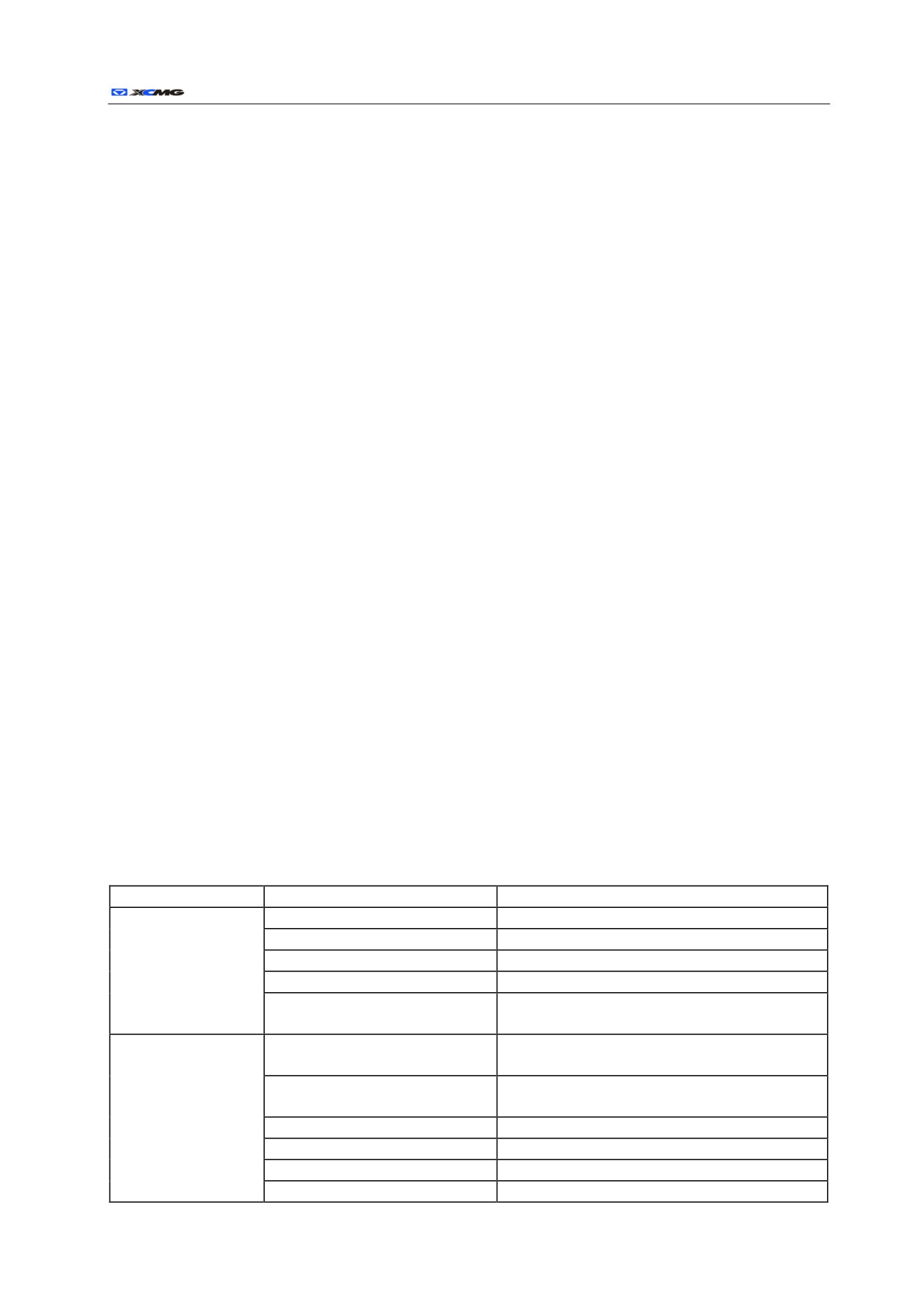
Trouble shooting
a)
Engine
Table 2-9 Trouble shooting of engine
Trouble
Cause
Remedy
No fuel
Add in fuel, and exhaust the air.
Wrong fuel
Empty the oil tank, and adopt the correct fuel.
Engine rotates, but it
Polluted fuel
Empty the oil tank, and add in clean fuel.
can’t be started or
Low capacity of battery
Charge or attach a new battery.
difficult to start.
Trouble of injection pump
Contact with the assigned dealer of XEM (Xugong
Excavator Machinery Co., Ltd) excavator
Trouble of preheat circuit or igniter
Contact with the assigned dealer of XEM excavator.
plug
Poor contact of circuit
Clean and fix the connection of battery and starting
motor.
Trouble of starting motor
Replace the starting motor.
Wrong engine oil
Drain the oil, and adopt the correct oil.
Blockage of air filter
Replace the filter elements.
Blockage of fuel filter
Bleed the air out of fuel system, and clean the sieve of
r
Operating and Maintenance Manual 132
fuel tank.
Low compression ratio of engine
Contact with the assigned dealer of XEM excavator.
Dirty nozzle or incorrect operation
Contact with the assigned dealer of XEM excavator.
Trouble of fuel cutoff linkage
Adjust or repair the linkage.
Leakage of fuel system
Check the connection of fuel system.
Air exists in fuel system.
Bleed the air.
Pop-up of fuel supply pump plunger
Push down and tighten the hand wheel.
Dirty transfer pump sieve
Clean or replace
Low level of engine oil
Add in engine oil.
Blockage of air suction system
Clean the filter system.
Dirty transfer pump sieve
Clean or replace
Off-time of injection pump
Contact with the assigned dealer of XEM excavator.
Shot noise, abnormal
Blockage of fuel filter
Renew the filter.
running or stoppage
of
Low temperature of cooling water
Incorrect operation of thermostat or it’s too cold.
engine
Water, dirt or air exists in fuel system
Drain the air out of fuel system, and clean the outlet
sieve of fuel tank.
Dirt or trouble of nozzle.
Contact with the assigned dealer of XEM excavator.
Fuel cutoff linkage trouble
Adjust or repair the linkage.
Blockage of air filter
Replace the filter elements.
Blockage of fuel pipe
Repair or replace the fuel pipe.
Polluted fuel
Empty the fuel tank, clean the outlet sieve, and add in
the oil again.
Blockage of fuel filter
Replace the filter.
Blockage of fuel tank cover vent hole
Clean or attach a new cover.
Dirt or trouble of fuel nozzle
Contact with the assigned dealer of XEM excavator.
Adjustment required for injection
Contact with the assigned dealer of XEM excavator.
The engine can’t
pump linkage
function fully.
Wrong fuel
Adopt the correct fuel.
Wrong engine oil
Adopt the correct engine oil.
Trouble of turbo charger
Contact with the assigned dealer of XEM excavator.
Off-time of injection pump
Contact with the assigned dealer of XEM excavator.
Blockage of emission
Remove the muffler and run the engine.
Overheat or overcooling of engine
See below
Trouble of engine
Contact with the assigned dealer of XEM excavator.
Leaks of air suction or bleeding
Contact with the assigned dealer of XEM excavator.
system
Low level of cooling water
Add in cooling water.
Trouble of thermostat
Contact with the assigned dealer of XEM excavator.
Overload of engine
Check the hydraulic safety valve.
Wear of radiator cap
Attach a new cap.
Blockage of radiator core and oil
Clean the radiator and oil cooler.
cooler core
Blockage of radiator mesh enclosure
Clean the mesh enclosure.
Off-time of injection pump
Contact with the assigned dealer of XEM excavator.
Overheat of engine
Damage of fan
Replace the fan.
Blockage of air filter
Clean the air filter.
Loosening of AC generator and fan
Tension the belt or attach a new belt.
belt
Wear of belt pulley
Replace the belt pulley
Dirty cooling system pipe
Flush the cooling system.
Trouble of thermometer or transfer
Contact with the assigned dealer of XEM excavator.
unit
Overlow temperature of
Trouble of thermostat
Contact with the assigned dealer of XEM excavator.
r
Operating and Maintenance Manual 133
cooling water
Trouble of thermometer or transfer
Contact with the assigned dealer of XEM excavator.
unit
Trouble of engine oil pump or pump
Contact with the assigned dealer of XEM excavator.
drive
Low level of engine oil
Add in engine oil.
trouble of engine oil pressure control
Contact with the assigned dealer of XEM excavator.
valve
Blockage of oil pump suction mesh
Low pressure of engine
Contact with the assigned dealer of XEM excavator.
enclosure
oil
Blockage of oil filter
Renew the oil filter.
Leak of engine oil
Leak check.
Engine oil is diluted by fuel or
Contact with the assigned dealer of XEM excavator.
cooling water.
Overhigh temperature of engine
Check the cooling system.
Wrong engine oil
Drain the oil, and adopt the correct oil.
Wrong engine oil
Drain the oil, and adopt the correct oil.
Leak of engine oil
Check the engine oil drain plug.
Excessive consumption
Overheat of engine
Check the cooling system.
of engine oil
Blockage of air filter
Clean the filter element or attach new filter elements.
Wear of inner parts of engine
Contact with the assigned dealer of XEM excavator.
Blockage or dirt of air suction system
Clean the air suction system.
Excessive consumption
Wrong fuel
Adopt the correct fuel.
of engine fuel
Dirty fuel nozzle
Contact with the assigned dealer of XEM excavator.
Off-time of injection pump
Contact with the assigned dealer of XEM excavator.
Wrong fuel
Empty the oil tank, and adopt the correct fuel.
Blockage or dirt of air suction or
Clean the air suction or discharge system.
discharge system
Too black or grey
Off-time of injection pump
Contact with the assigned dealer of XEM excavator.
exhaust fume
Dirty fuel nozzle or its incorrect
Contact with the assigned dealer of XEM excavator.
operation
Trouble of engine body
Contact with the assigned dealer of XEM excavator.
Failure of engine
Trouble of battery
Charge or replace.
Loose connection or corrosion
Clean, tighten or replace the battery.
Loosening of AC generator belt
Tension the belt or attach a new belt.
Insufficient capacity of
AC generator fails to charge.
Contact with the assigned dealer of XEM excavator.
battery
Broken fuse
Replace the fuse.
Trouble of key switch
Replace the key switch.
Insufficient capacity of battery or
Charge or replace the battery.
damaged
Poor connection of battery circuit
Clean the connection.
Broken fuse
Replace the fuse.
Trouble of key switch
Contact with the assigned dealer of XEM excavator.
Starting motor can’t
Trouble of starting relay
Contact with the assigned dealer of XEM excavator.
rotate.
Trouble of starting motor magnetic
Contact with the assigned dealer of XEM excavator.
coil
Trouble of starting motor
Repair or replace the starting motor.
The starting motor pinion is clamped
Repair or replace starting motor.
in the flywheel gear.
Trouble of engine body
Contact with the assigned dealer of XEM excavator.
Poor connection of battery or starting
Clean the connection part.
motor circuit
Magnetic vibration of
Low capacity of battery
Charge or replace battery
starting motor
Opening of starting motor magnetic
Contact with the assigned dealer of XEM excavator.
“hold” coil
r
Operating and Maintenance Manual 134
Disengagement of starting motor
Contact with the assigned dealer of XEM excavator.
pinion with the flywheel gear
The starting motor
Seizure or trouble of pinion shift
rotates but it can’t be
Contact with the assigned dealer of XEM excavator.
mechanism
started.
Fracture of pinion teeth
Contact with the assigned dealer of XEM excavator.
Fracture of flywheel gear teeth
Contact with the assigned dealer of XEM excavator.
Inner damages or fracture of battery
Check and replace the leads.
leads
Slow starting of engine
Loosening of battery or starting motor
Clean and tighten the connection.
connection or corrosion
Wrong fuel.
Empty the oil tank, and adopt the correct fuel.
Low temperature of engine
Run the engine until it becomes hot.
The engine bleeds white
Trouble or overcooling of thermostat
Contact with the assigned dealer of XEM excavator.
gas.
Off-time of injection pump
Contact with the assigned dealer of XEM excavator.
Leak of cooling water into the
Contact with the assigned dealer of XEM excavator.
cylinder of engine
Bearing is not lubricated.
Insufficient oil pressure, check the blocked oil pipe of
turbo charger
Worn bearing
Contact with your assigned dealer.
Air leaks of engine, suction or drain
Large noise or vibration
Check or repair.
pipe
of turbo charger
Improper gap between the turbine and
Contact with the assigned dealer of XEM excavator.
turbine case
Breakage of turbine blade
Remove the exhaust elbow and air inlet hose, and
check them.
Damage or wear of bearing and (or)
Contact with the assigned dealer of XEM excavator,
worn seal
check and clean the air filter, check if the service
interval of engine is proper or dirt enters into the
Oil dripping of turbo
engine.
charger joint
Overhigh pressure of crankcase
Check the vent pipe, ensure the pipe is not blocked, and
clean it.
Blockage of turbo charger return pipe
Remove the pipe, and check or clean it.
at the exhaust pipe
The combustion deposits cause the
check or clean
blockage of coal behind the turbine.
Leaks of air suction pipe cause the
check or clean
Too large resistance of
blockage of dirt behind the
turbo charger rotating
compressor wheel.
member
Overhigh temperature, unbalanced
Contact with the assigned dealer of XEM excavator.
impeller, dirty oil, lack of oil or
insufficient lubrication causes the
seizure, dirt and wear of bearing.
r
Operating and Maintenance Manual 135
b)
Electric system
Table 2-10 Trouble shooting of electric system
Trouble
Cause
Remedy
Current leakage of battery or it can’t hold
Replace the battery.
the charge capacity.
Slow starting of engine
“Draggle” of starting motor
Contact with the assigned dealer of XEM
excavator.
Low voltage of battery
Charge or replace battery
Trouble of starting relay
Contact with the assigned dealer of XEM
excavator.
Suction of starting motor magnetic coil
Contact with the assigned dealer of XEM
The starting motor continues to
excavator.
run after starting the engine.
The starting motor can’t be disconnected.
Contact with the assigned dealer of XEM
excavator.
Trouble of key switch
Contact with the assigned dealer of XEM
excavator.
Loosening or slipping of AC generator
Check the belt, if slipped, replace; if loose,
belt
tension.
Low speed of engine
Adjust the speed to the specified value.
Attached accessories cause the electric
Remove the attached accessories or install
overload.
higher-output AC generator.
Loosening of battery, grounding steel
The charging indicator goes
on
Check, clean or tighten the electric
strip, starting motor or AC generator,
during the running of engine.
connection.
corrosion of electric connection
Low voltage of battery
Charge or replace the battery.
AC generator trouble
Contact with the assigned dealer of XEM
excavator.
Trouble of monitor
Contact with the assigned dealer of XEM
excavator.
Worn driving belt
Replace the belt.
Worn belt pulley
Replace the belt pulley and belt.
Improper adjustment of belt pulley
Adjust the installation of AC generator
Fracas of AC generator
Trouble of AC generator bearing
Loosen the belt of AC generator, and turn the
belt pulley by hands. In case of feeling
difficult to turn, repair AC generator.
Contact with the assigned dealer of XEM
Trouble of monitor
excavator.
Contact with the assigned dealer of XEM
Indicator of monitor can’t go on.
Trouble of electric wiring
excavator.
Damaged fuse
Replace the fuse.
Trouble of sensor.
Check the sensor.
Damaged fuse
Replace the fuse.
Contact with the assigned dealer of XEM
Trouble of thermometer
excavator.
The cooling water thermometer
Check the sensor of cooling water
fails to work.
Trouble of temperature sensor
thermometer.
Contact with the assigned dealer of XEM
Trouble of electric circuit
excavator.
Damaged fuse
Replace the fuse.
The automatic idling indicator
Contact with the assigned dealer of XEM
goes out.
Trouble of automatic idling switch
excavator.
r
Operating and Maintenance Manual 136
Damaged fuse
Replace the fuse.
Contact with the assigned dealer
of
XEM
Damaged fuel meter
The fuel meter can’t work.
excavator.
Contact with the assigned dealer
of
XEM
Trouble of electric circuit
excavator.
Contact with the assigned dealer
of
XEM
Trouble of mode toggle
excavator.
Working mode toggle fails to
Contact with the assigned dealer
of
XEM
Damaged electric joint
work.
excavator.
Contact with the assigned dealer
of
XEM
Trouble of monitor
excavator.
Contact with the assigned dealer
of
XEM
Trouble of walking mode switch
excavator.
Contact with the assigned dealer
of
XEM
Trouble of monitor
Fast/slow
walking
speed
excavator.
deactivates.
Contact with the assigned dealer
of
XEM
Trouble of solenoid valve
excavator.
Contact with the assigned dealer
of
XEM
Damaged running motor
excavator.
Damaged fuse
Replace the fuse.
Contact with the assigned dealer
of
XEM
Trouble of pilot pressure switch
excavator.
Contact with the assigned dealer
of
XEM
Trouble of electric circuit
Automatic idling deactivates.
excavator.
Contact with the assigned dealer
of
XEM
Trouble of engine control motor
excavator.
Contact with the assigned dealer
of
XEM
Trouble of main controller
excavator.
Once or
Contact with the assigned dealer of XEM
Contact with your assigned dealer.
brighten.
excavator.
Contact with the assigned dealer
of
XEM
Twice
Abnormal current of motor
excavator.
Contact with the assigned dealer
of
XEM
Three times
Pause of motor action
excavator.
Contact with the assigned dealer
of
XEM
Four times
Motor poor in the range of action
excavator.
The
trouble
Broken circuit or short circuit of built-in
Contact with the assigned dealer
of
XEM
indicator
Five times
potentiometer of motor
excavator.
flashes.
Set broken circuit or short circuit of
Contact with the assigned dealer
of
XEM
Six times
potentiometer
excavator.
Contact with the assigned dealer
of
XEM
Seven times
Abnormal current of magnetic coil
excavator.
Contact with the assigned dealer
of
XEM
Eight times
Overlow speed of engine
excavator.
Contact with the assigned dealer
of
XEM
Extinguish
Trouble of controller
excavator.
c)
Hydraulic system
Table 2-11 Trouble shooting of hydraulic system
Trouble
Cause
Remedy
Low level of hydraulic oil
Fill the hydraulic oil up to full scale.
Low temperature of hydraulic oil
Preheat the machine.
Wrong use of hydraulic oil
Empty the oil tank, and adopt the correct hydraulic oil
Slow hydraulic
function
Overlow speed of engine
Accelerate or contact with your assigned dealer.
Wear of hydraulic pump
Contact with the assigned dealer of XEM excavator.
Blockage of pump suction pipeline
Contact with the assigned dealer of XEM excavator.
Wrong use of hydraulic oil
Adopt the correct hydraulic oil
Air leak of pump oil suction pipeline
Contact with the assigned dealer of XEM excavator.
Overheat of
hydraulic oil
Blockage of hydraulic pipeline
Contact with the assigned dealer of XEM excavator.
Low level of hydraulic oil
Fill the hydraulic oil to full scale.
r
Operating and Maintenance Manual 137
Blockage of filter
Attach a new filter
Wear of hydraulic pump
Contact with the assigned dealer of XEM excavator.
Blockage of radiator or oil cooler
Clean and straighten the blade.
Bypass of oil cooler
Contact with the assigned dealer of XEM excavator.
Trouble of safety valve
Contact with the assigned dealer of XEM excavator.
Polluted hydraulic oil
Drain the oil and fill it up.
Improper adjustment of hydraulic components
Contact with the assigned dealer of XEM excavator.
Air leak of the pipe from oil tank to pump
Contact with the assigned dealer of XEM excavator.
Twist or depression of hydraulic pipeline
Check the pipeline.
Foaming
of
Wrong hydraulic oil
Adopt the correct hydraulic oil.
hydraulic oil
Water in hydraulic oil
Replace the hydraulic oil.
Overhigh or overlow oil level
Calibrate the oil level.
Wrong hydraulic oil
Adopt the correct hydraulic oil.
Improper adjustment of hydraulic components
Contact with the assigned dealer of XEM excavator.
Low or no oil
No hydraulic oil in the system
Fill up the correct hydraulic oil.
pressure
Worn hydraulic cylinder packing
Contact with the assigned dealer of XEM excavator.
Trouble of safety valve
Contact with the assigned dealer of XEM excavator.
Wear of hydraulic pump
Contact with the assigned dealer of XEM excavator.
Reduction of set pressure of main safety valve
Contact with the assigned dealer of XEM excavator.
of control valve
No
hydraulic
function (fracas of
Low level of hydraulic oil
Fill up the hydraulic oil.
pump)
Damage of oil suction pipeline or hose
Contact with the assigned dealer of XEM excavator.
Blockage of suction filter, and air sucked in
Clean the filter system.
oil suction.
Wear of hydraulic pump
Contact with the assigned dealer of XEM excavator.
Low pressure of main safety valve
Contact with the assigned dealer of XEM excavator.
The
hydraulic
cylinder acts but it
Low level of hydraulic oil
Fill up the hydraulic oil.
can’t lift the load.
Blockage of suction filter
Clean the filter system.
Leakage of pump suction pipeline
Check the oil suction pipeline.
Low pressure of safety valve
Contact with the assigned dealer of XEM excavator.
Damage of pipe or hose
Repair or replace
Loosening of hydraulic joint
Tighten.
One control lever
Damage of O-ring in the joint
Attach a new O-ring.
fails to work.
hydraulic pump trouble
Contact with the assigned dealer of XEM excavator.
Trouble of pilot valve
Contact with the assigned dealer of XEM excavator.
Damage of pilot pipeline
Repair or replace
Control valve column is damaged or polluted
Contact with the assigned dealer of XEM excavator.
by dirt.
Damage of hydraulic pipeline
Repair or replace
One
hydraulic
Loosening of joint
Tighten.
cylinder fails to
work.
Damage of O-ring in the joint
Attach a new O-ring.
Trouble of pilot valve
Contact with the assigned dealer of XEM excavator.
Damage of pilot pipeline
Repair or replace
r
Operating and Maintenance Manual 138
Leakage of hydraulic cylinder seal
Contact with the assigned dealer of XEM excavator.
One
hydraulic
Damage of hydraulic cylinder lever
Contact with the assigned dealer of XEM excavator.
cylinder fails to
Damage of pilot pipeline
Repair or replace
work or almost
deactivates.
Trouble of pilot valve
Contact with the assigned dealer of XEM excavator.
Trouble of circuit
Contact with the assigned dealer of XEM excavator.
Two travel motors
Trouble of center sub body
Contact with the assigned dealer of XEM excavator.
fail to work.
Trouble of travel motor
Contact with the assigned dealer of XEM excavator.
Unreleased of brake
Contact with the assigned dealer of XEM excavator.
One travel motor
fails to work
Trouble of pilot valve
Contact with the assigned dealer of XEM excavator.
Damage of pilot pipeline
Repair or replace
Adjustment required for crawler
Adjust the crawler sag
Damage of crawler guide wheel, supporting
Contact with the assigned dealer of XEM excavator.
wheel or carrying wheel
Unstable travel
Bend of chassis frame
Contact with the assigned dealer of XEM excavator.
Seizure of stone block or soil in the chassis
Remove and repair.
frame
Unreleased of moving brake
Contact with the assigned dealer of XEM excavator.
Trouble of rotary motor
Contact with the assigned dealer of XEM excavator.
Rotation
deactivates.
Trouble of pilot valve
Contact with the assigned dealer of XEM excavator.
Trouble of rotary gear
Contact with the assigned dealer of XEM excavator.
Unsmooth
Trouble of rotary bearing
Contact with the assigned dealer of XEM excavator.
rotation.
Lack of grease
Add in the grease.
r
Operating and Maintenance Manual 139
Periodic replacement of parts
In order ensure the safety of operation, be sure to check the machine at regular intervals. If any of the
following parts is damaged, it may cause a severe accident or fire. The deterioration or damage of these parts
is difficult to determine via a visual check, so these parts shall be replaced at the intervals shown in the table
below, however, if they are found to be poor during the check, they shall be replaced before the operation of
machine, regardless of the interval of replacement.
In case of replacing the hose, it’s also required to check their pipe clips for deformations, breakage or
damages, and replace them according to the demands. Be sure to check all the following hoses at regular
intervals, and replace or tighten any poor part as per the demands.
Table 2-12 Periodic Replacement of Key Parts
Part replaced at regular intervals
Replacement interval
Fuel hose (from fuel tank to filter)
Every two years
Engine
Fuel hose (from fuel tank to injection pump)
Every two years
oil filter hose (from engine to oil filter)
Every two years
Oil pump inlet hose
Every two years
Basic body
Oil pump outlet hose
Every two years
Hydraulic hose of rotation gear
Every two years
Hose of movable arm hydraulic cylinder pipeline
Every two years
Hydraulic
system
Hose of bucket rod hydraulic cylinder pipeline
Every two years
Accessories of
Hose of bucket hydraulic cylinder pipeline
Every two years
working device
Hose of pilot pipeline
Every two years
r
Operating and Maintenance Manual 140
Transport, storage and protection
Transport
Cautions of transport
z
During the attachment of machine to the platform of truck or trailer, or removal of machine
from them
a)
During the transport of machine on the road, be sure to follow the local laws and regulations.
b)
Provide the appropriate truck or trailer for the convenience of machine transport.
z
Cautions of machine removal
a)
Choose the firm or flat ground.
b)
Be sure to adopt the platform or slope.
c)
During the removal of machine, there must be a signalman.
d)
Choose the slow-speed mode with a travel mode toggle to avoid
Fig.3-1
high-speed.
e)
The steering on the slope is very dangerous, and avoids the
steering when going up or down the slope.
If the steering is required, transport the machine back to the ground or trailer platform, and drive it on
the slope after rectifying the direction.
f)
In case of driving up or down the slope, don’t use any other control lever other than the traction
control lever.
g)
The intersection of slope top and trailer platform is convex, and drive the machine by this
intersection.
h)
Avoid the possible injuries caused by the turnover of machine during the rotation of upper car.
i)
Keep the bucket rod retracted down and rotate the upper car slowly to achieve the optimum stability.
j)
Fix the frame of machine with a chain or rope.
r
Operating and Maintenance Manual 141
Road transport
During the transport of machine on the road, learn of and follow all the local laws and regulations.
z
During the transport of trailer, verify the length, width, height and weight of trailer for loading the
machine.
Note: the transport weight and size may be different due to the type installed track plate or
front working device.
z
Observe the conditions of transport route in advance, e.g. size, weight limit and traffic regulations. In
case of disassembling the machine, meet the local specified size or weight limit.
Removal of trailer
Remove the machine always on the firm or flat ground.
Note: be sure to use the platform or slope during the loading and unloading.
z
Adopt the slope or platform.
a)
Clean the slope or platform and trailer platform thoroughly before
loading and unloading, the risk of slipping may exist on them with
oil dirt, soil or ice.
b)
During the use of slope or platform, place the damp block under the
Fig.3-2
wheel of front body and trailer.
c)
The slope or platform must have enough width, length and strength
to make the inclination angle of slope or the gradient of platform below 15°.
z
Loading
a)
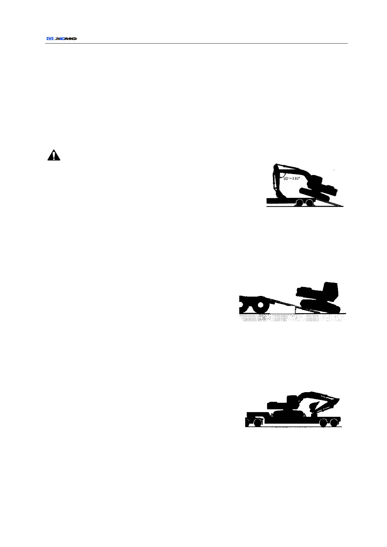
The direction of machine is down: with front-end working device: move the working device forward
with it placed on front body; without front-end working device: travel in reverse direction as shown in
above figure.
b)
The centerline of machine shall be on the centerline of
trailer.
Below 15°
c)
Drive the machine slowly on the slope. With front-end
working
Fig.3-3
device:
1)
Support the plane bucket on the trailer, and the angle
between
bucket rod and movable arm should be within 90º to 110º.
2)
Upon inclining the machine to trailer platform, support the bucket to the trailer, move the machine
slowly forward, until the whole crawler moves on the trailer
and contacts the platform.
3)
Lift the bucket slightly, retract the bucket rod and make it
under the machine, and rotate the upper car slowly by 180º.
Fig. 3-4
4)
Fall the bucket to sleeper.
d)
Stop the engine, and remove the key from key switch.
e)
Move the control lever several times until the whole pressure of hydraulic cylinder is released.
f)
Pull the safety locking rod to LOCK (lock).
g)
Close the window, skylight and door of cab, and cover the air outlet to prevent the wind and rain from
entering into it.
r
Operating and Maintenance Manual 142
Note: in the cold weather, be sure to heat the machine before loading/unloading it.
z
Transport
Note: tie the chain or rope to the frame of machine, and don’t make the chain or rope pass
through or pressed on the hydraulic pipe or hose.
a)
Place the damp blocks before and behind the crawler to fix the machine.
b)
Fix four corners of machine and front-end working device to the trailer with a chain or rope.
z
Unloading
Note: make the intersection of trailer platform rear end and slope convex, and drive the
machine by it carefully.
Important: avoid any possible damage of front-end working device. During the unloading, keep the
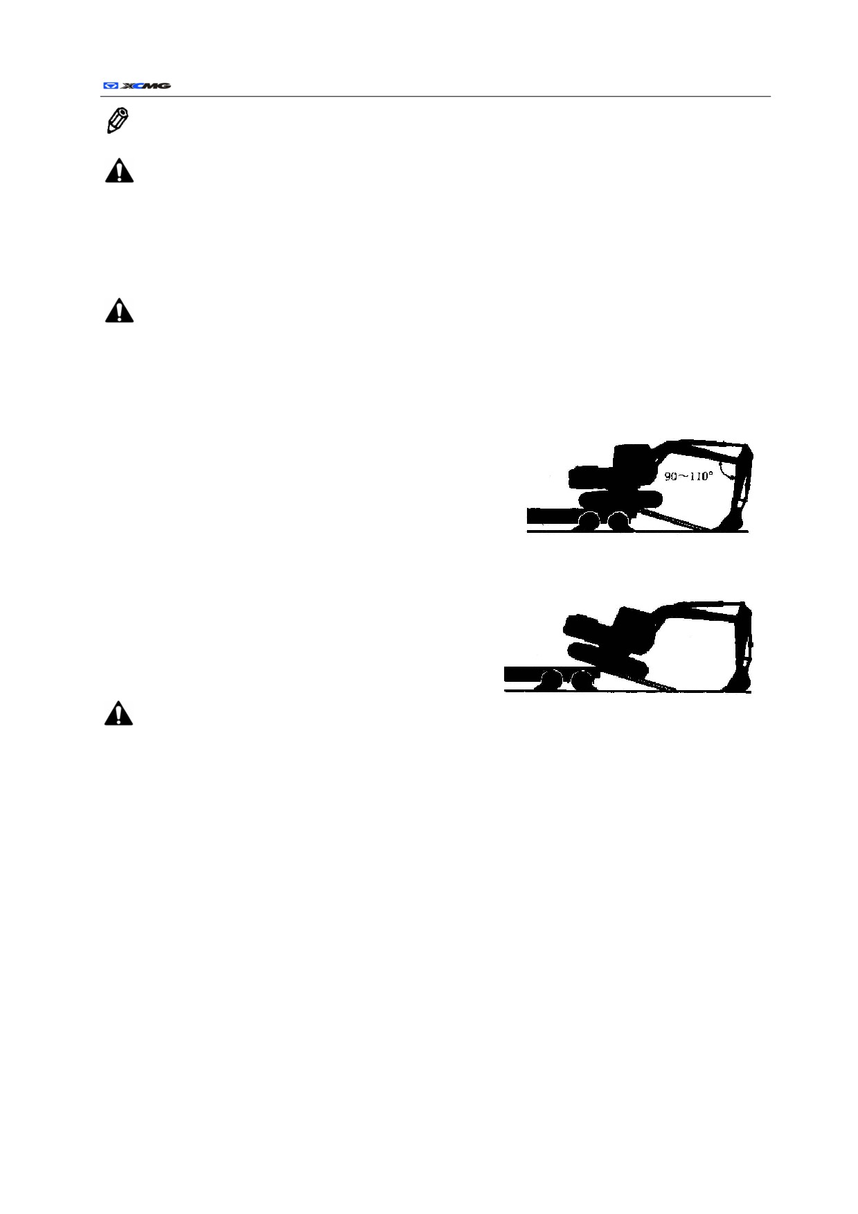
angle between the bucket rod and movable arm within 90° to 110º always, retract the bucket rod, and
any unloading may cause the damages to machine.
a)
Upon moving the tail end of machine through the trailer to the slope or platform, support the bucket
plane on the ground, and make the angle between bucket
rod and movable arm within 90º to 110º.
Important: avoid any possible damage of hydraulic
cylinder, and avoid any fierce collision of bucket to
the ground.
Fig. 3-5
b)
Place the bucket on the ground before the machine starts
to incline forward.
c)
During the forward movement of machine, lift the
movable arm and stretch the bucket rod until the
machine drives fully under the slope or platform.
● Lifting method of machine
Fig. 3-6
:
1)
Lifting steel rope and other lifting tools may be
broken, which results in the serious injury of person. Don’t use any damaged or aged steel rope
or lifting tool.
2)
For correct lifting methods, types or sizes of lifting steel rope and lifting tools, contact with the
assigned dealer.
3)
Pull the safety locking rod to LOCK (lock), and avoid any unexpected movement of machine
during the lifting.
4)
Incorrect lifting methods and incorrect mounting of steel rope will cause the movement of
machine during the lifting, which results in the damages to machine and injuries to the persons.
5)
Don’t lift the machine rapidly, otherwise the lifting steel rope and lifting tools will be
overloaded and may lead to their fracture.
6)
Don’t let any person approachable to the lifted machine or walk under it.
7)
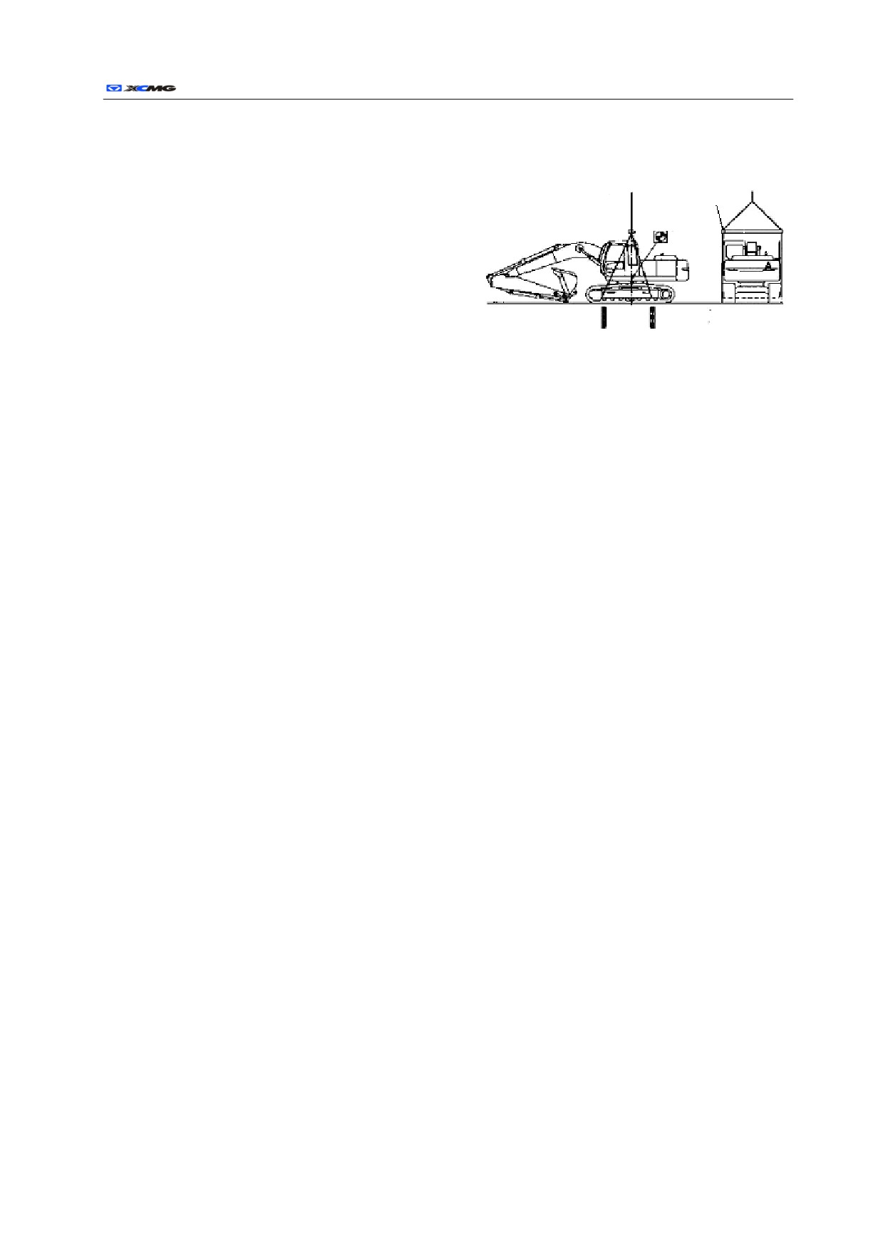
The gravity center marked on the machine is for the machine of standard specifications, but the
actual gravity center will be changed as per the type of installed accessory or chosen device and
their position. Therefore, ensure the balance of machine can’t be lost in case of lifting the
r
Operating and Maintenance Manual 143
machine.
For the bucket rod and bucket hydraulic cylinder that are fully extended, fall the movable arm until
the bucket contacts the ground.
Supporting lever
a)
Pull the safety locking rod to LOCK (lock).
Gravity center
b)
Stop the engine, and remove the key from key
switch.
c)
Adopt the steel rope and supporting rod with
enough length, make them not contact the
machine during the lifting. Wrap some protective
Fig. 3-7
material around the steel rope or supporting rod as
per the demands to avoid the damages to machine.
d)
Drive the crane in proper lifting position.
e)
As shown in Fig.3-7, make the steel rope pass under the chassis frame on both sides, and attach it to
the crane.
r
Operating and Maintenance Manual 144
Storage and protection
Daily and short-term storage and protection
z
Check the machine, repair the worn and damaged parts. If necessary, attach new parts.
z
Clean the air filter element.
z
If possible, retract all the hydraulic cylinders; if impossible, apply the grease to the exposed rod of
hydraulic cylinder.
z
Lubricate all the lubrication points.
z
Place the crawler on the long and stable damp block.
z
Clean the machine.
z
After charging the battery up, remove the battery and store it at dry and safe place. If not, separate the
connection of battery negative-pole cable on the wiring terminal (-).
z
Add the anti-rust agent into engine coolant. In winter, adopt the anti-freezing agent or drain the
coolant off. If the cooling system is emptied, be sure to hang a nameplate “No Water of Radiator” in
conspicuous position.
z
Loosen the belts of AC generator and cooling fan.
z
Apply the paint to desired positions to avoid rusting.
z
Store the machine at dry and safe place. In case of storing it outdoor, adopt the water shield.
Long-term storage
z
Storage place
a)
Commonly store in the ventilated and dry warehouse.
b)
If the device is stored in open air, park it on the concrete ground easy to drain the water, cover and fix
the canvas or hood, and store it at the place that can’t be invaded by natural disaster and without
corrosive or harmful substance or gas.
z
Storage
a)
Use the hydraulic functions of moving, rotation and digging twice to three times every month to
lubricate all the parts. Check the level of coolant and lubrication state before the operation.
b)
Check the appearance quality, protection side and anti-corrosion substances, etc at regular intervals.
Use preparation after storage
z
Remove the coverings.
z
Remove the protective substances painted on the exposed part.
z
Charge the battery, mount or connect it.
z
After draining the oil of engine crankcase, renew the oil.
z
After draining the gear oil in the rotary and traction reducer, renew the gear oil.
z
Drain the inclusions and mixed water out of the hydraulic oil tank and fuel tank.
z
Apply the grease to each hinged position.
z
Fill in the coolant as per the specification.
z
For the check before the operation, refer to the relevant regulations of operation.
r
Operating and Maintenance Manual 145
Technical specifications
Product specification
Model
Item
XE210C
XE210C3Ⅶ
XE210C2
XE210C2Ⅶ
Operation configuration under
2.91m
2.91m
2.91m
2.91m
Bucket lever
Bucket lever
Bucket lever
standard configuration
Bucket lever
Kerb mass, kg
20850~21450
20850~21450
20850~21450
20850~21450
Standard bucket capacity, m3
0.8~0.91
0.8~0.91
0.8~0.91
0.8~0.91
CumminsQSB6.7
CumminsQSB6.7
CumminsB5.9
Model
CumminsB5.9
116
116
112
Engine
Rated power, kW
112
2000
2000
1950
Rated speed, r/min
1950
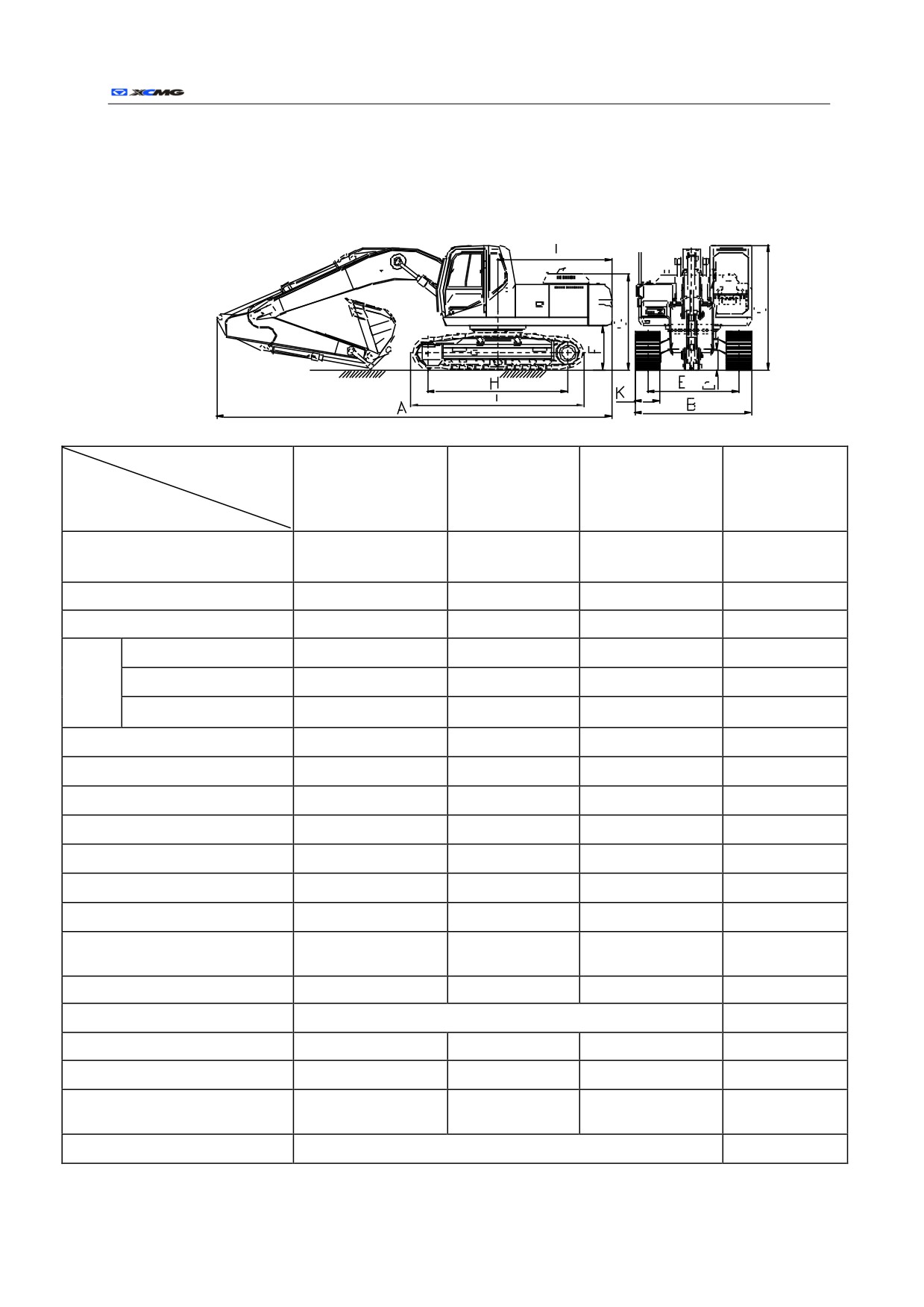
A: Total length (transport), mm
9500~9550
9500~9550
9500~9550
9500~9550
B: Total width (transport), mm
2800~3000
2800~3000
2800~3000
2800~3000
C: Cab height (transport), mm
2950~3100
2950~3100
2950~3100
2950~3100
D: Minimum ground clearance, mm
460~500
460~500
460~500
460~500
E: Crawler track, mm
2180~2400
2180~2400
2180~2400
2180~2400
F: Get-on ground clearance, mm
1030~1085
1030~1085
1030~1085
1030~1085
G: Height of engine cover, mm
2200~2300
2200~2300
2200~2300
2200~2300
H: Distance between the centers of
3350~3480
3350~3480
3350~3480
3350~3480
driving wheel and guide wheel, mm
2750
J: Rotating radius of tail, mm
2750
2750
2750
K: Width of track plate, mm
600(three grousers track plate)
46.3
Grounding pressure, kPa
47.3
47.3
46.3
Maximum rotary speed, r/min
12.5
12.5
12.5
12.5
Max. traveling speed (fast/slow),
5.5/3.3
5.5/3.3
5.5/3.3
5.5/3.3
km/h
Gradeability, °
≤35 (70%)
r
Operating and Maintenance Manual 146
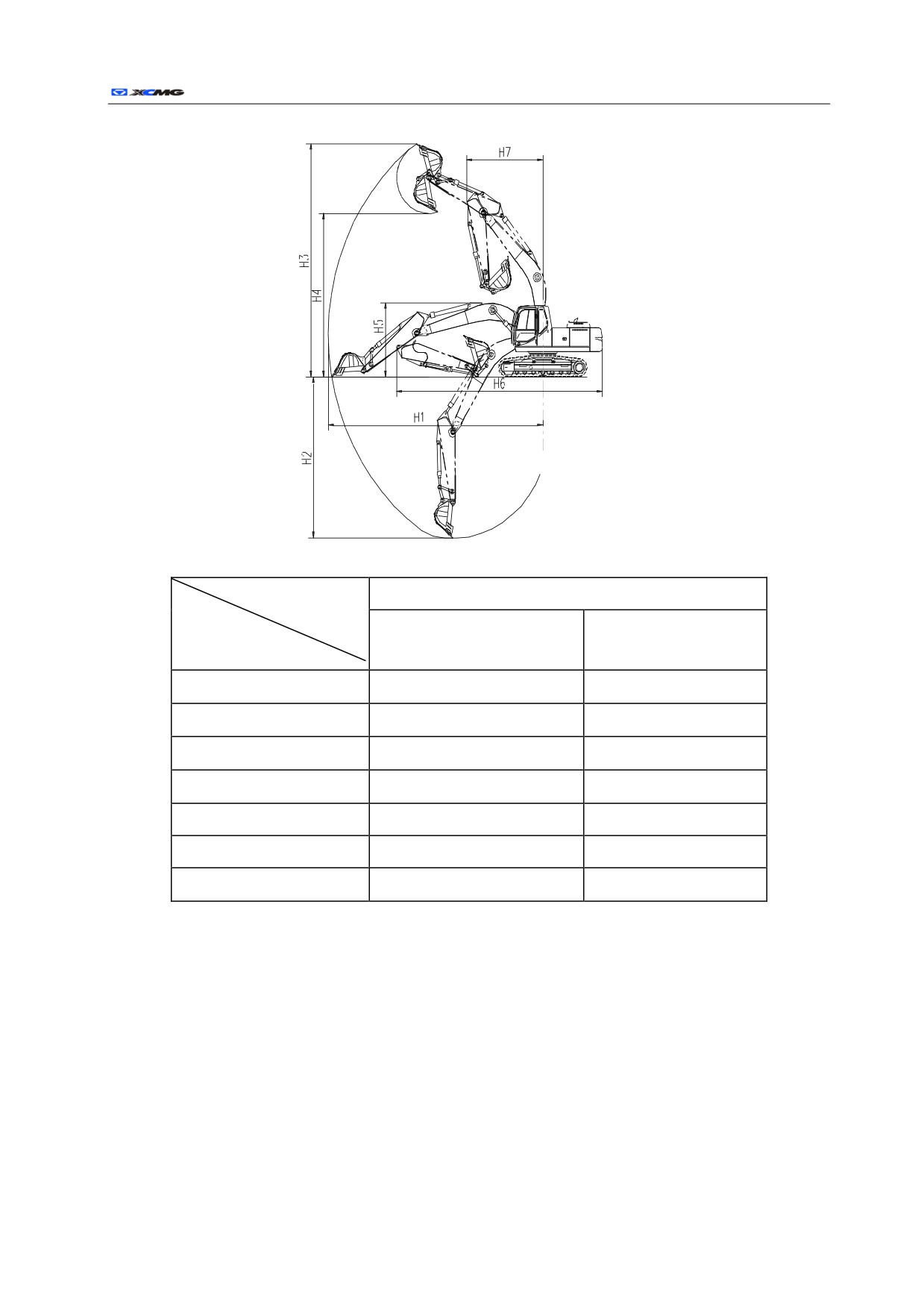
Operation range
Model
XE210C/XE210C3Ⅶ/XE210C2/XE210C2Ⅶ
Item
2.53m
2.91m
Bucket Lever
Bucket Lever
H1: maximum digging radius,
9680
9925
mm
H2: maximum digging depth,
mm
6280
6655
H3: maximum digging height,
9745
9640
mm
H4: maximum unloading
height, mm
6860
6800
H5: transport height, mm
2985
2985
H6: total transport length, mm
9520
9520
H7: minimum rotary radius,
mm
3530
3530
r
Operating and Maintenance Manual 147
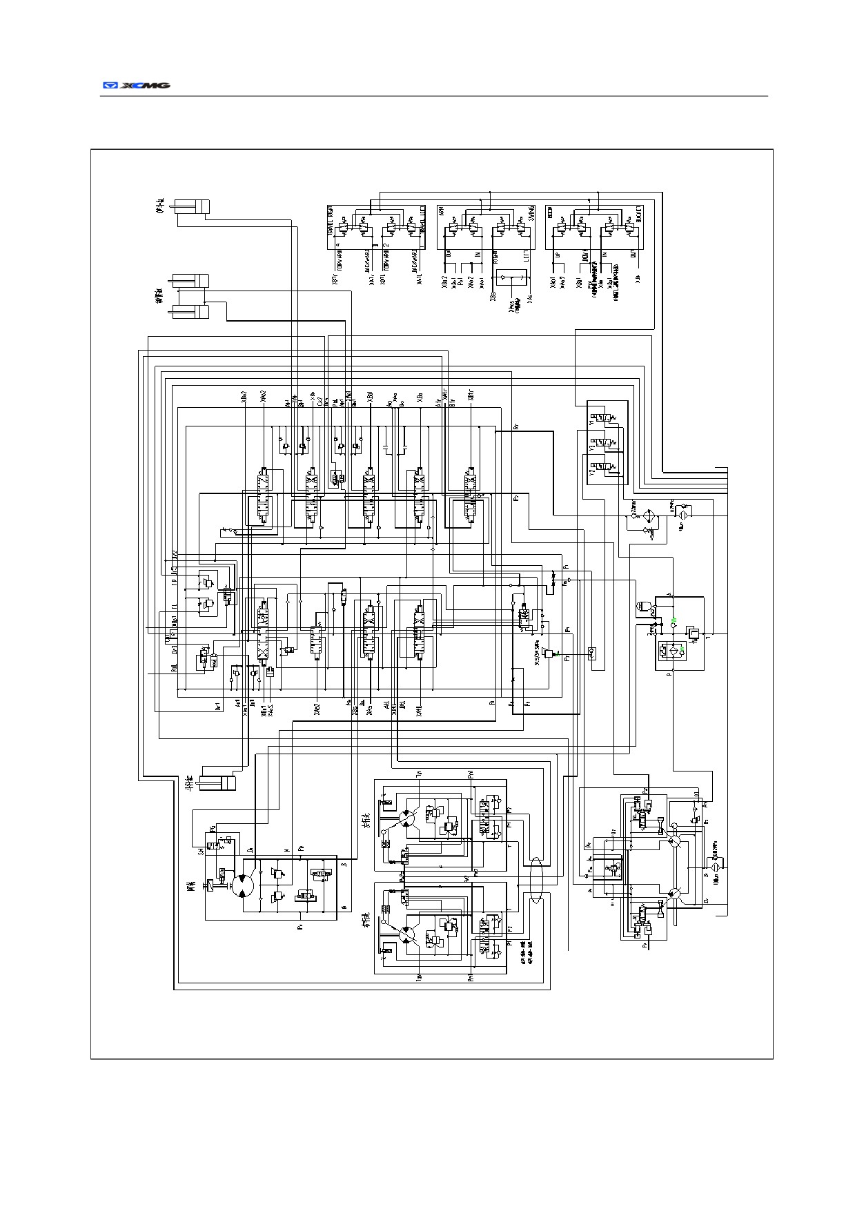
Hydraulic System Schematic