SANY Crawler Hydraulic Excavator (SY195C9, SY205C9, SY215C9, SY225C9). Shop Manual (2013) - page 18
Testing and Adjusting
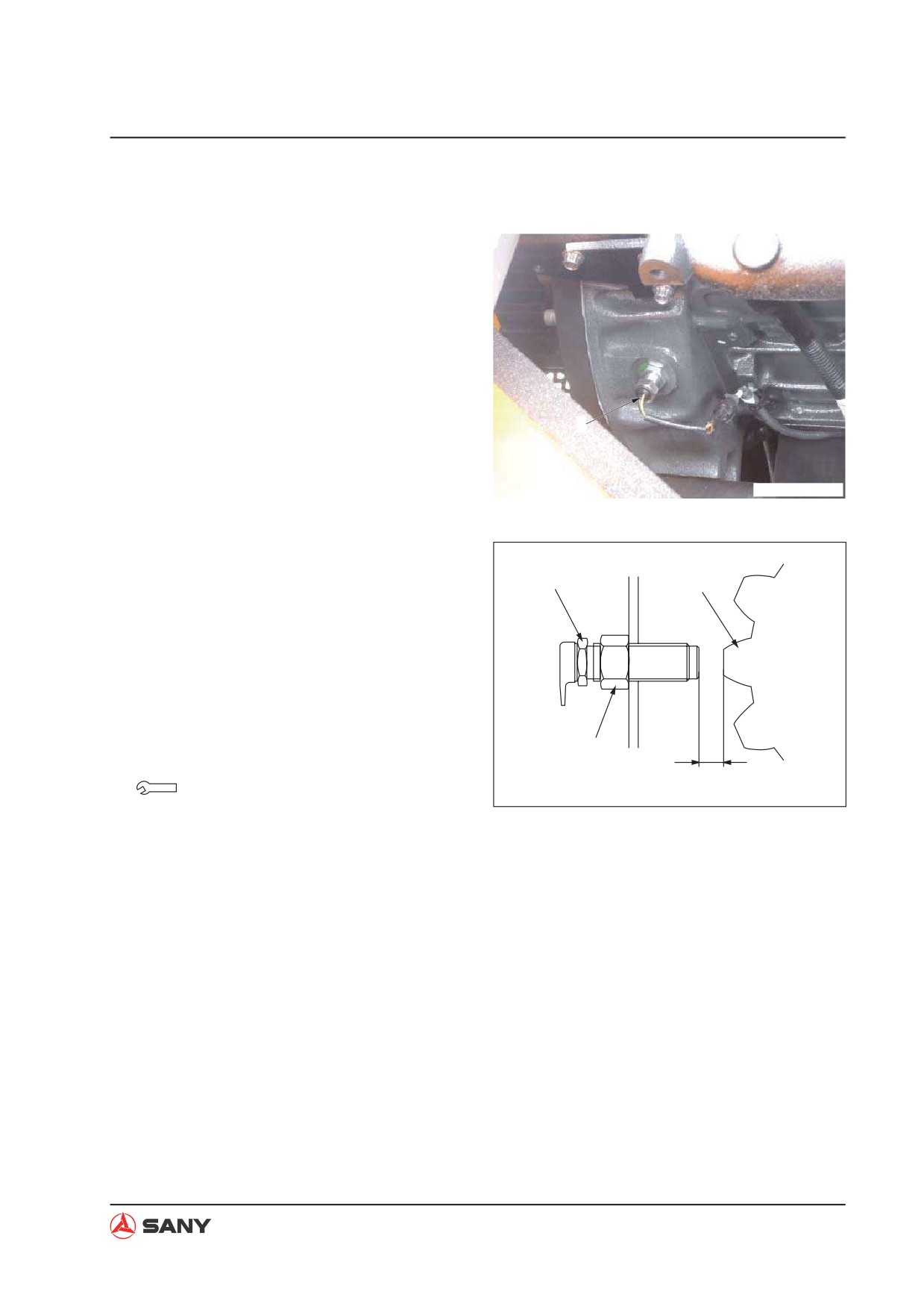
6.7 Engine Speed Sensor - Adjust
NOTE: Remove the engine speed sensor (1)
before adjusting. Check for presence of metal
chips and for damaged sensor top. Restore
the sensor.
1
ZXT215-1004001
1. Screw on the sensor (1) until its end con-
tacts with ring gear tip (2) of the flywheel.
1
2
2. Unscrew the sensor some degrees.
Degrees: 1.2~1.4 turns
Adjust the clearance (a) between the
sensor end and the flywheel edge to 2±0.2
mm.
3
3. Tighten the sensor (1) with the nut (3).
a
Nut: 49.0~68.6 N·m {5~7kg·m}
ZX215-1004021
4. Make sure that the engine speed is dis-
played properly on the control panel after
adjustment.
6-19
Testing and Adjusting
6.8 A/C Compressor Belt Tension - Test and Adjust
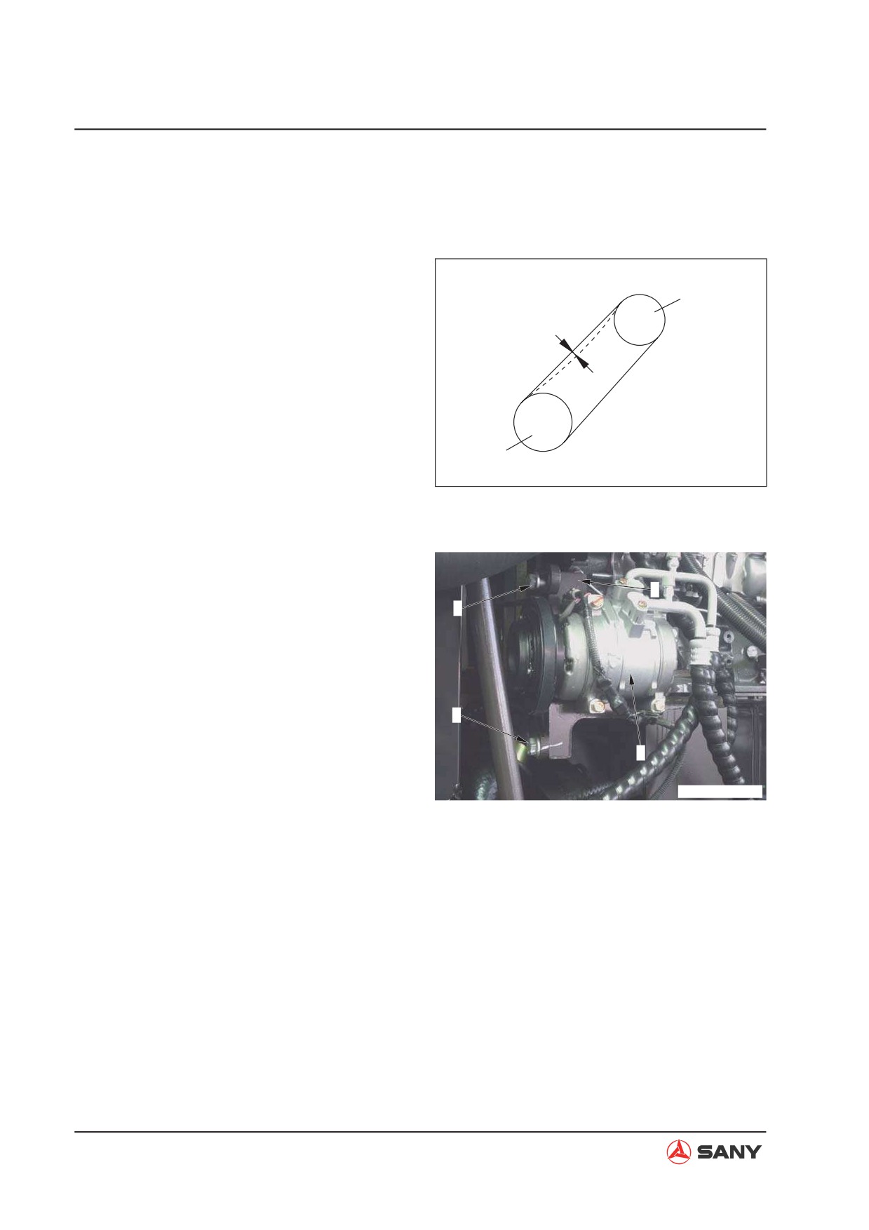
6.8.1 Testing
Press the intermediate point of the belt be-
Compressor Belt
tween the drive pulley and the compressor pul-
Pulley
ley with a finger force of about 58.8 N(6kgf),
and measure deflection (A) of the belt, which
A
shall be 5~8 mm (0.20 in~0.31in).
Drive Pulley
ZX215-1004022
6.8.2 Adjusting
NOTE: If the belt deflection is abnormal, adjust
it according to the following procedure.
4
1. Loosen the bolts (1) and (2).
1
2. Move the compressor (3) and the bracket
(4) together to adjust belt tension.
3. After positioning the compressor (3), tight-
en the bolts (1) and (2).
2
4. Check belt tension again after adjustment.
3
ZXT215-1004002
6-20

Testing and Adjusting
Reference
Use a tensiometer to check the compressor
belt tension.
New Belt
Used Belt
637±108 N
441±88.2 N
{65±11 kgf}
{45±9 kgf}
NOTE:
Ɣ Check each belt for damage. Check the
V-groove and the V-belt for wear. In addi-
tion, it is especially important to keep the
V-belt free from friction with bottom of the
V-groove.
Ɣ Contact local Sany dealer and replace the
belt in case of the following conditions.
Ɣ The fan belt has been stretched and
little margin is left for adjustment.
Ɣ Cuts or cracks are found in the belt.
Ɣ Abnormal sliding or noise.
Ɣ When a new belt is mounted, readjust the
belt tension after one hour operation.
6-21
Testing and Adjusting
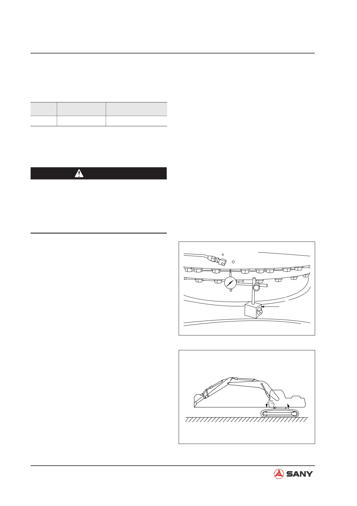
6.9 Swing Bearing Clearance - Measure
Measuring tool
Symbol
Part Number
Part Name
H
60033930
Dial gauge
Ɣ
The following steps are to be followed
when measuring the clearance of swing
bearing.
CAUTION
Ɣ
Park your machine on a level ground.
Lower your work equipment to the
ground.
Ɣ
Do not put your hands or feet under the
undercarriage during measurement.
1.
Fix the dial gauge (H) to the track frame
and apply the probe to the lower end of the
outer race.
2.
Place the work equipment to the maxi-
mum reach position. Raise the bucket to
a height that the bucket tips and the swivel
table bottom are on the same level.
H
At the moment, the front of upper structure
lowers while the rear rises.
ZX215-1004023
3.
Set the dial gauge (H) to zero.
4.
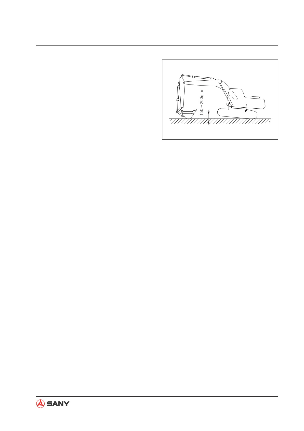
Set the arm almost perpendicular to the
ground and lower the boom until the front
track shoe floats.
At the moment, the front of upper structure
rises while the rear lowers.
5.
Read the dial gauge (H).
6.
Restore the machine to the condition of
ZX215-1004024
6-22
Testing and Adjusting
step 2. Check the dial gauge (H) to see if it
reads zero.
The value indicated by the dial gauge (H)
is the clearance of the bearing.
For more information, see “Swing bearing”
on page 4-13.
ZX215-1004025
Repeat step 3 through step 5 if the dial
gauge (H) reads a value other than zero.
6-23
Testing and Adjusting
6.10 Track Tension - Test and Adjust
6.10.1 Testing
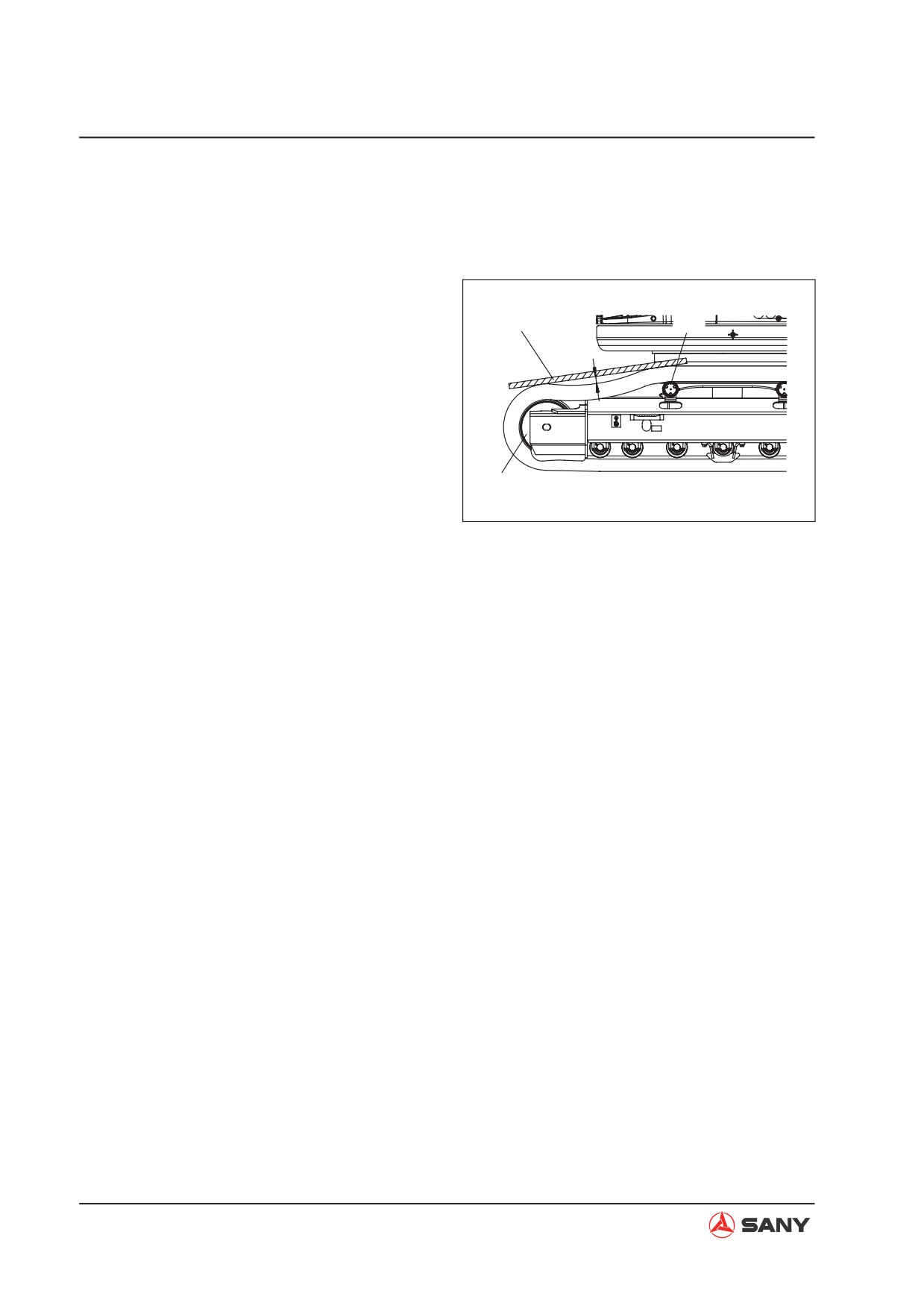
1. Move your machine forward for a distance
that is equal to the length of track on the
3
2
ground. Keep running the engine at low
idle. Park your machine slowly.
a
2. Place a straight bar on the track over idler
(1) and carrier roller (2).
NOTE: A straight angle steel bar is recom-
mended for this purpose as it has good
1
resistance to bending strain.
ZX215-1004026
3. Measure the maximum clearance (a) be-
tween the upper surface of track and the
lower edge of the straight bar.
Ɣ Max. clearance (a): 10~30 mm (0.4~1.2
in)
6-24
Testing and Adjusting
6.10.2 Adjusting
Ɣ
If track tension is incorrect, make adjust-
ment as per the following instruction.
CAUTION
Ɣ
Do not loosen the valve over one turn.
If the valve is loosened too much, the
grease under high pressure may cause
the valve to eject.
1.
Reduce track tension
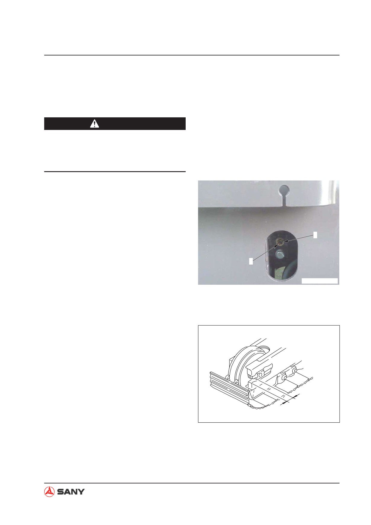
1) Loosen the valve (1) to discharge
grease. Tighten the valve after dis-
charging.
2) Check the track tension again as per
1
the above method after adjustment.
2.
Increase track tension
2
1) Add grease through the grease fitting
(2) with a grease gun.
ZXT215-1004003
2) Check the track tension again as per
the above method after adjustment.
NOTE: Add grease until the gap (b) be-
tween the idler guide and the track frame
end becomes zero. If the tension is till low,
it indicates that the pins and bushings are
seriously worn. Replace the pins and bush-
ings, or remove a piece of track shoe.
b
ZX215-1004027
6-25
Testing and Adjusting
6.11 Hydraulic Pressure in Hydraulic Circuits - Test and Adjust
Testing and adjusting tools
ID
Part Number
Part Name
60038932
Hydraulic Tester
—
B210770000084
Adaptor
NOTE: The hydraulic pressure in work equip-
ment, swing and travel (hydraulic pump out-
put) circuits can be viewed on the monitor.
6.11.1 Measuring
CAUTION
Ɣ
Lower the work equipment to the
ground and stop the engine. Operate
the control levers for several times to
release the residual pressure in hydrau-
lic circuits.
Ɣ
Open the butterfly nut on the breather
valve and press the relief button to re-
lease pressure in the hydraulic tank.
1.
Preparatory work before measuring
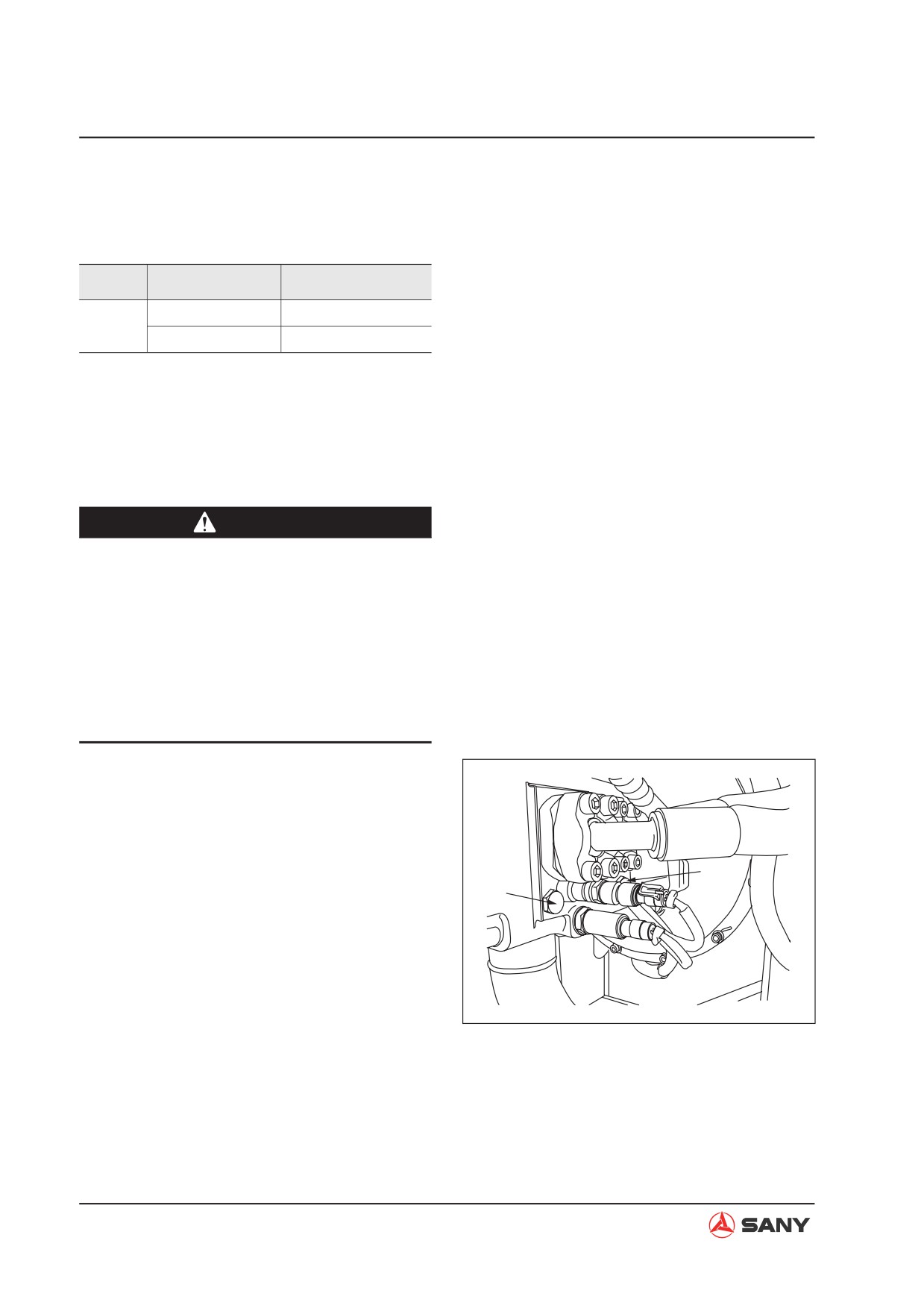
1) Remove the plug (1) and plug (2) for
measuring the hydraulic pressure.
Ɣ Plug (1): For oil circuit of rear pump
2
1
Ɣ Plug (2): For oil circuit of front pump
2) Install the priming adaptor and connect
it to the hydraulic tester.
Ɣ Use an oil pressure gauge with a ca-
pacity of 40 MPa {408 kgf/cm²}.
ZX215-1004028
3) Start the engine and keep it running
until the hydraulic pressure rises to a
point within the operational range.
6-26
Testing and Adjusting
2. Measurement of unloading pressure
1) Start the engine.
2) Measure the hydraulic pressure when
the engine is running at high idle and
all control levers are in a neutral posi-
tion.
NOTE: The hydraulic pressure indicat-
ed is the pressure when the unloading
valve unloads.
3. Measurement of work equipment pres-
sure at relief
1) Start the engine and move the cylinder
to be measured to its stroke end.
2) Measure the hydraulic pressure when
the engine is running at high idle and
the cylinder is in relief condition.
NOTE: The hydraulic pressure indicat-
ed is the pressure when the main relief
valve is in relief condition.
4. Measurement of swing pressure at relief
1) Start the engine. Reach out the work
equipment as far as possible. Lower
the work equipment on the ground in
order to restrict swinging.
2) Measure the hydraulic pressure when
the engine is running at high idle and
the swing circuit is in relief condition.
NOTE: The hydraulic pressure indi-
cated is the pressure when the swing
motor relief valve is in relief condition.
NOTE: The relief pressure of swing
motor is lower than the main relief pres-
sure.
6-27
Testing and Adjusting
5. Measurement of travel pressure at relief
1) Start the engine and lock the travel
mechanism.
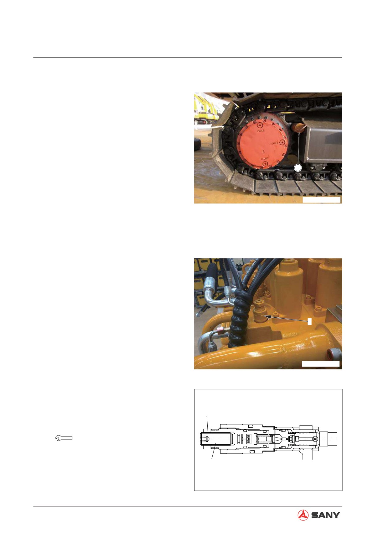
NOTE: Place the pin (1) between the
sprocket and the track frame to lock the
travel mechanism.
2) Measure the hydraulic pressure when
the engine is running at high idle and
1
the travel circuit is in relief condition.
NOTE: The hydraulic pressure indicat-
ed is the pressure when the main relief
ZXT215-1004004
valve is in relief condition. When the
travel circuit is in relief condition, the
pressure indicated is always the pres-
sure at high relief.
6.11.2 Adjusting
NOTE: The boom relief valve cannot be ad-
justed.
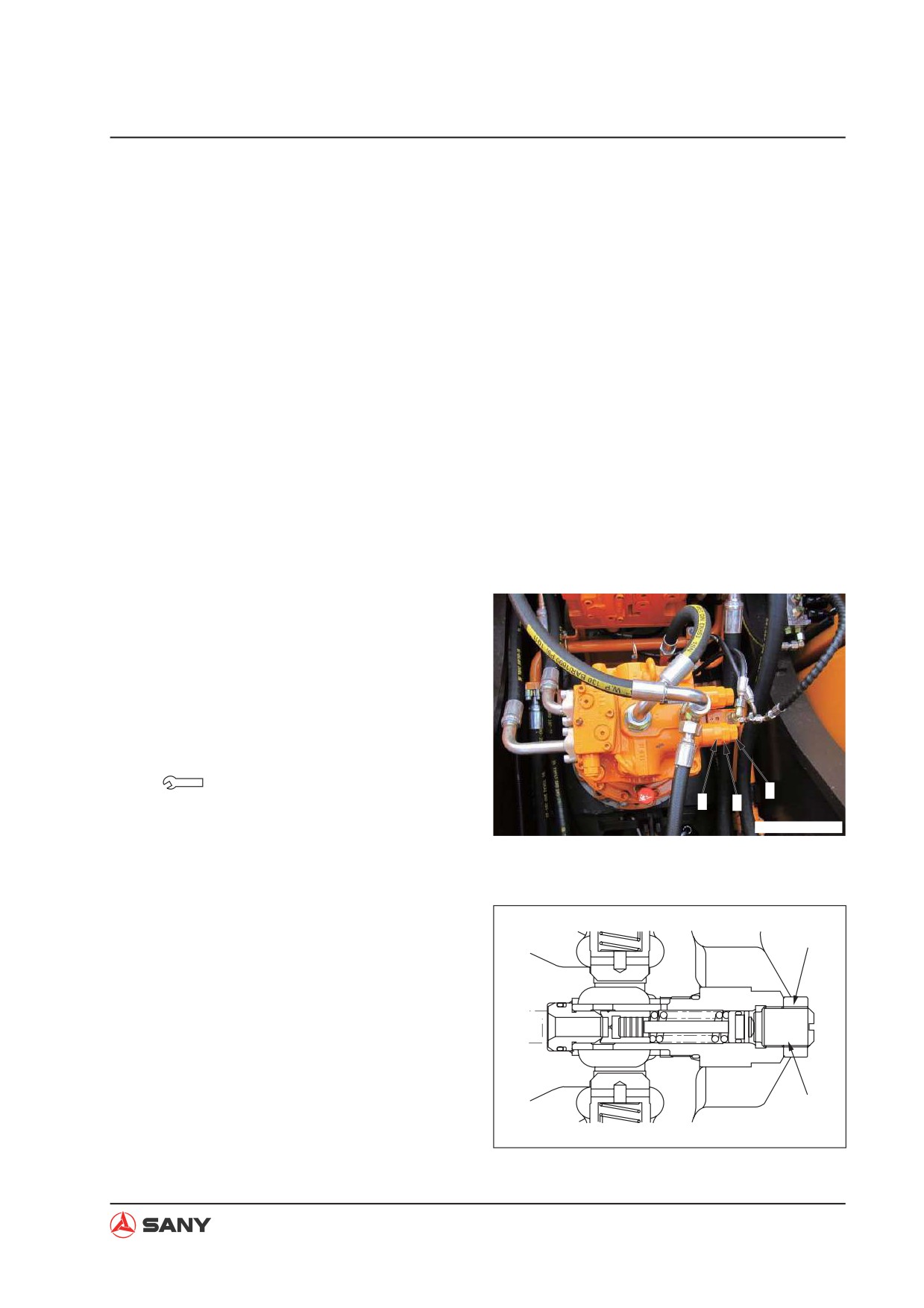
1. Adjustment of main relief pressure
NOTE: If the high relief pressure is abnor-
3
mal, adjust the high pressure setting of the
main relief valve (3) as per the following.
1) Disconnect the pilot hose.
2) Loosen the locknut (4). Turn the adjust-
ZXT225-1104002
ment screw (5) to adjust the pressure.
Pressure rises as the screw turns right.
Pressure drops as the screw turns left.
Each turn of the screw equals about:
4
12.5 MPa {128 kgf/cm²}
Locknut:
53.5±4.9 N·m {5.5±0.5 kgf·m}
5
ZX215-1004029
6-28
Testing and Adjusting
3) Check the pressure again after adjust-
ment. Measure the pressure according
to the procedure described above.
Ɣ Connect the pilot hose before measur-
ing the pressure.
Ɣ Adjustment of the high pressure setting
side will affect the low pressure setting
side. The low pressure setting side is,
therefore, to be adjusted too.
2.
Adjustment of swing relief pressure
NOTE: If the swing relief pressure is ab-
normal, adjust the swing motor relief valve
(6) as per the following.
1) Loosen the locknut (7). Turn the adjust-
ment screw (8) to adjust the pressure.
Pressure rises as the screw turns right.
Pressure drops as the screw turns left.
Each turn of the screw equals about:
6.71 MPa { 68.4 kgf/cm²}
Locknut:
8
6
7
78-103 N·m{8.0-10.5 kgf·m}
ZXT225-1104003
2) Check the pressure again after adjust-
ment. Measure the pressure according
to the procedure described above.
7
8
ZX215-1004030
6-29
Testing and Adjusting
6.12 Control Circuit Oil Pressure - Test and Adjust
Testing and adjusting tools
ID
Part Number
Part Name
21008760
Hydraulic Tester
—
B210770000084
Adaptor
6.12.1 Testing
CAUTION
Ɣ
Lower the work equipment to the
ground and stop the engine. Operate
the control levers for several times to
release the residual pressure in hydrau-
lic circuits.
Ɣ
Open the butterfly nut on the breather
valve and press the relief button to re-
lease pressure in the hydraulic tank.
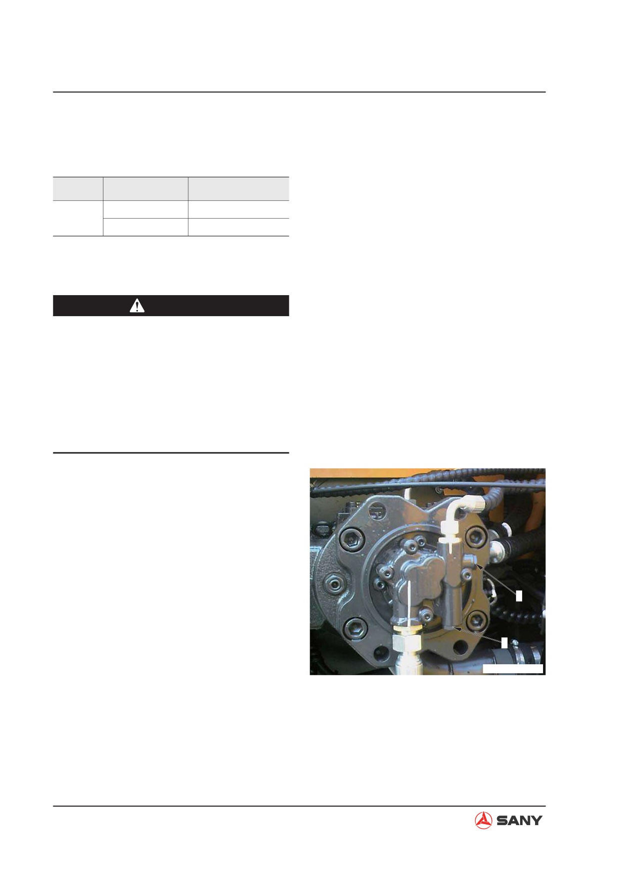
1.
Remove the plug (1) for measuring the hy-
draulic pressure.
2.
Install the priming adaptor and connect it
to the hydraulic tester.
Use an oil pressure gauge with a capacity
of 6 MPa{61 kgf/cm²}
3.
Start the engine and keep it running until
1
the hydraulic pressure rises to a point with-
in the operational range.
4.
Measure oil pressure when the engine is
2
running at high idle and all control levers
ZXT215-1004007
are in a neutral position.
6-30
Testing and Adjusting
6.12.2 Adjusting
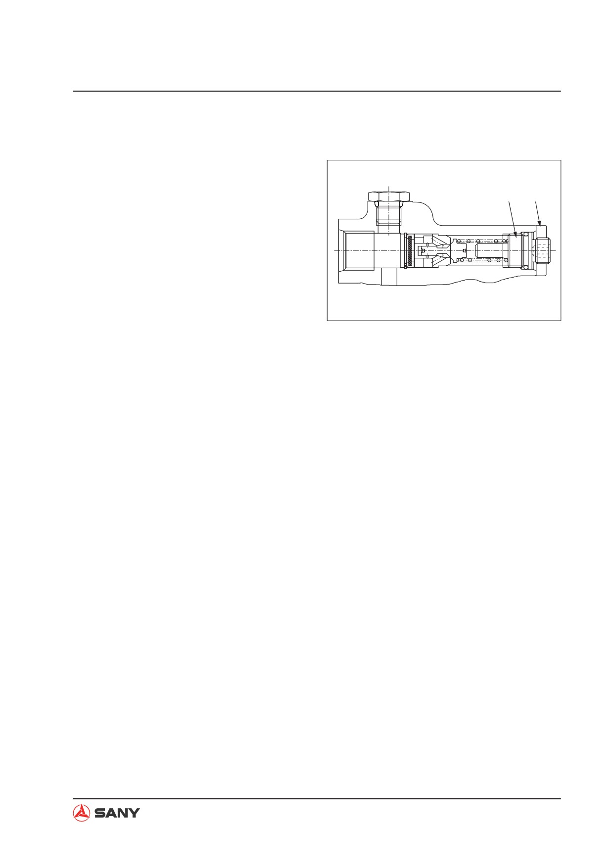
1. If the measurement is less than 3.5 kgf/
cm², loosen the retaining nut (2) and screw
in adjusting stud (3). Watch the change
3
2
of readings on the pressure gauge at the
same time. Tighten the retaining nut (2)
when proper pressure value is achieved.
2. Remove all the tools after measurement
and make sure the machine returns to its
normal condition.
ZX215-1004031
6-31
Testing and Adjusting
6.13 Solenoid Valve Output Pressure - Measure
Measuring tools
ID
Part Number
Part Name
21008760
Hydraulic Tester
—
B210770000084
Adaptor
NOTE: Make sure that the initial pressure of
control oil circuit is normal before measuring
the output pressure of solenoid valve.
CAUTION
Ɣ Lower the work equipment to the
ground and stop the engine. Operate
the control levers for several times to
release the residual pressure in hydrau-
lic circuits.
Ɣ Open the butterfly nut on the breather
valve and press the relief button to re-
lease pressure in the hydraulic tank.
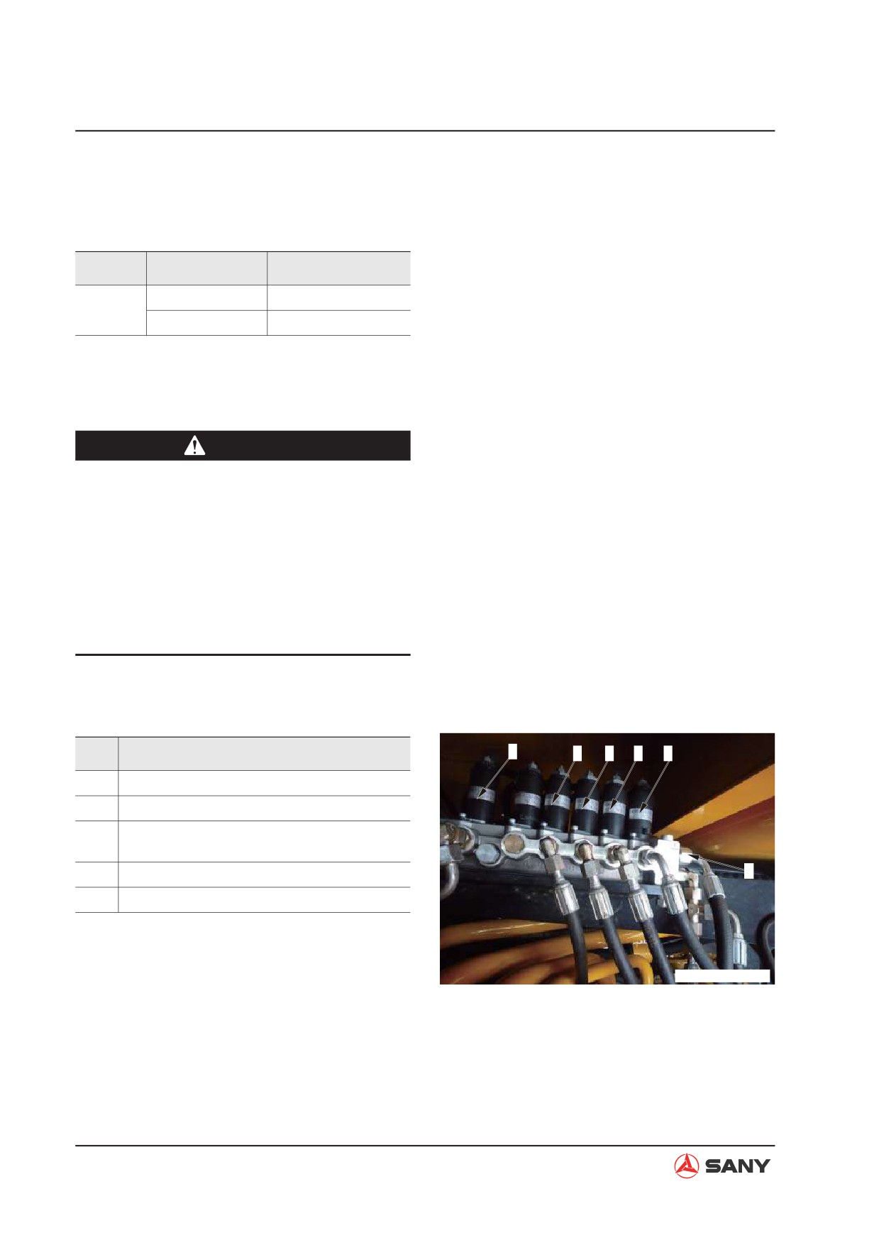
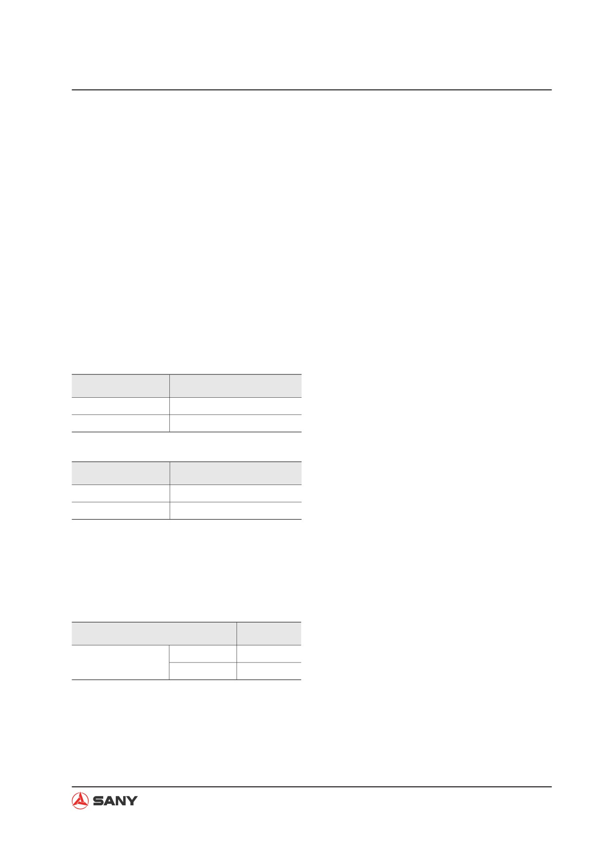
1. Disconnect the hose of solenoid valve to
measure the pressure at the outlet.
No.
Solenoid Valves to be Measured
5
4
3
2
1
1
Solenoid valve - high/low travel speed
2
Solenoid valve - swing priority
Solenoid valve - bucket confluence/difflu-
3
ence
4
Solenoid valve - boom priority
A
5
Solenoid valve - pilot lockout
2. Install a tee to location (A) on each sole-
noid valve and connect the hose.
WXT215-1206001G
3. Mount the adaptor onto the tee and con-
nect it to the hydraulic tester.
Use a hydraulic tester with a capacity of 6
MPa{61 kgf/cm²} .
6-32
Testing and Adjusting
4. Start the engine and keep it running un-
til the hydraulic oil temperature rises to a
point within the operational range.
5. Run the engine at full speed. Operate the
control levers to open or close each sole-
noid valve, and measure the pressure.
Ɣ The function of each solenoid valve
can be checked through the monitor's
monitoring function. (This is a special
function of the monitor.)
Ɣ When each output pressure reads the
following values, the solenoid valve is
normal.
High speed travel
Solenoid Valve
Output Pressure
OFF (de-energize)
0 {0}
ON (energize)
3.9~4.1 MPa{39~41 kgf/cm²}
Swing priority
Solenoid Valve
Output Pressure
OFF (de-energize)
0 {0}
ON (energize)
3.0~3.9 MPa{30~39 kgf/cm²}
6. Remove all measuring tools after measure-
ment. Make sure that the machine returns
to its normal condition.
Table of functioning state - pilot lock solenoid
valve
Functioning State
Function
Lock
OFF
Lockout control
Free
ON
6-33
Testing and Adjusting
6.14 Pilot Valve Output Pressure - Measure
Measuring tools
ID
Part Number
Part Name
21008760
Hydraulic Tester
—
B210770000084
Adaptor
NOTE: Make sure that the initial pressure of
control oil circuit is normal before measuring
the output pressure of pilot valve.
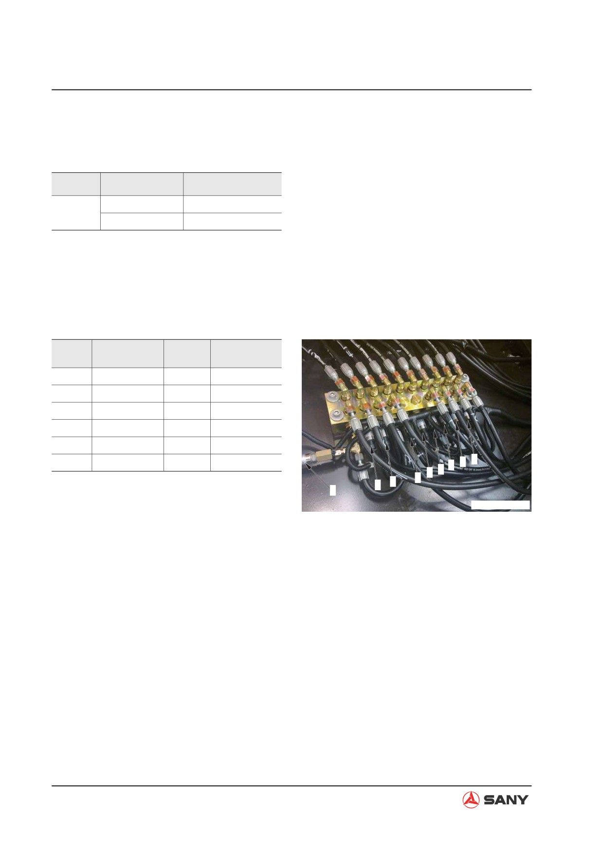
1. Remove the pilot pressure switch.
Oil Circuit
Oil Circuit
No.
No.
Measured
Measured
1
Travel left
7
Bucket DUMP
2
Travel right
8
Arm IN
3
Arm OUT
9
Swing
4
Bucket DIG
5
Boom DOWN
6
Boom UP
2
1
3
4
5
6
7
2. Install the adaptor and connect it to the hy-
8
9
draulic tester.
ZXT225-1104005
Use a hydraulic tester with a capacity of 6
MPa {61kgf/cm²}
3. Start the engine and keep it running un-
til the hydraulic oil temperature rises to a
point within the operational range.
4. Measure the output pressure when the en-
gine is running at high idle and all control
levers of the tested circuit are in neutral
position or at full stroke.
6-34

Testing and Adjusting
NOTE: When the measured output pres-
sure reads the following values, the pilot
valve is normal.
Control Lever
Hydraulic Pressure
Neutral
0{0}
Close to the average initial pres-
Full stroke
sure of oil control circuit
(See Table of Standard Values)
5. Remove all measuring tools after measure-
ment. Make sure that the machine returns
to its normal condition.
6-35
Testing and Adjusting
6.15 Pilot Valves (Work Equipment and Swing) - Adjust
Ɣ
If the play of work equipment or swing con-
trol lever is excessive, make adjustment as
per the following procedure.
1.
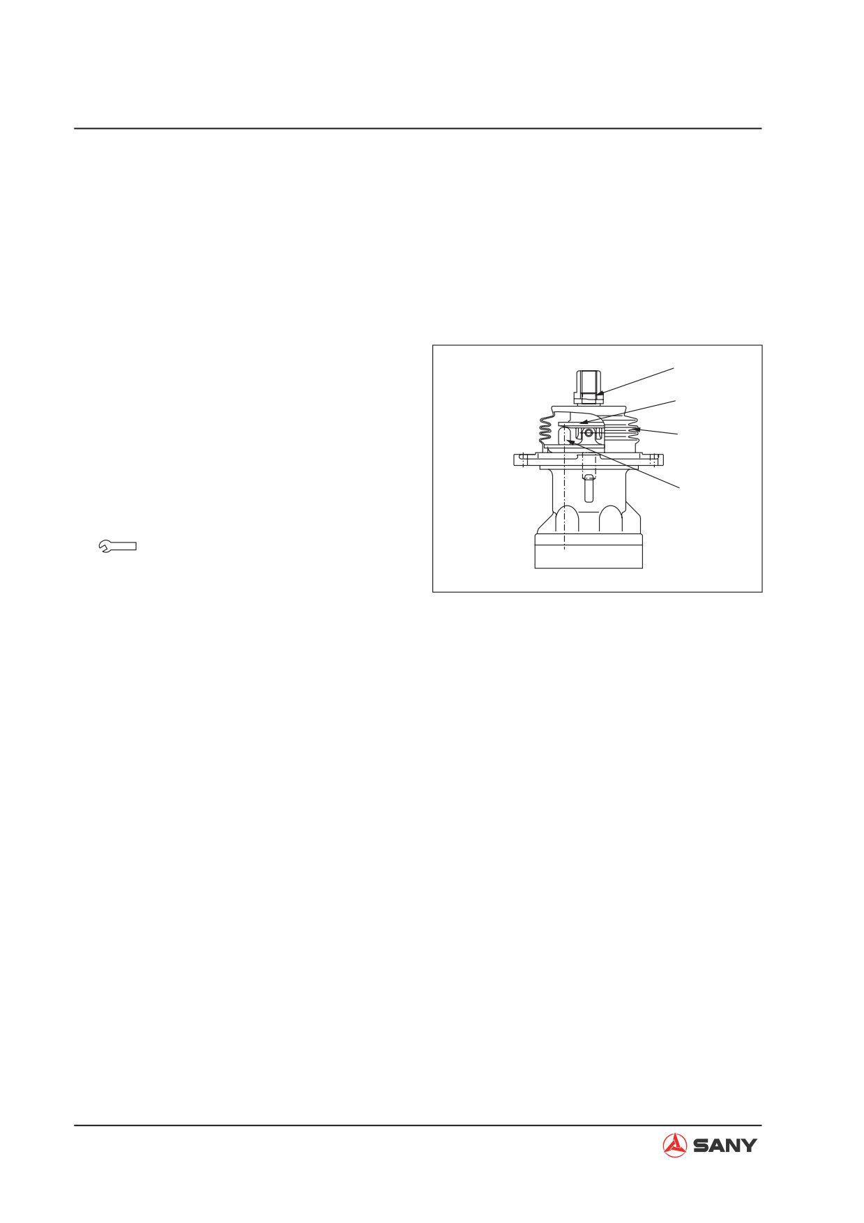
Remove the work equipment and swing pi-
lot valve assembly.
2.
Remove the rubber sleeve (1).
2
3.
Loosen the locknut (2). Screw on the disc
3
(3) until it contacts with the four heads of
plunger (4).
1
NOTE: Do not move the plunger.
4
4.
When the disc (3) is fixed, tighten the lock-
nut (2) to specified torque.
Locknut:
98~127 N·m {10~13 kgf·m}
ZX215-1004032
5.
Install the rubber sleeve (1).
6.
Install the work equipment and swing pilot
valve assembly.
6-36
Testing and Adjusting
6.16 Work Equipment Hydraulic Drift - Test
NOTE: If hydraulic drift exists in the work
equipment cylinder, check it according to the
following procedure and determine whether
the failure lies in the cylinder seal or in the
control valve.
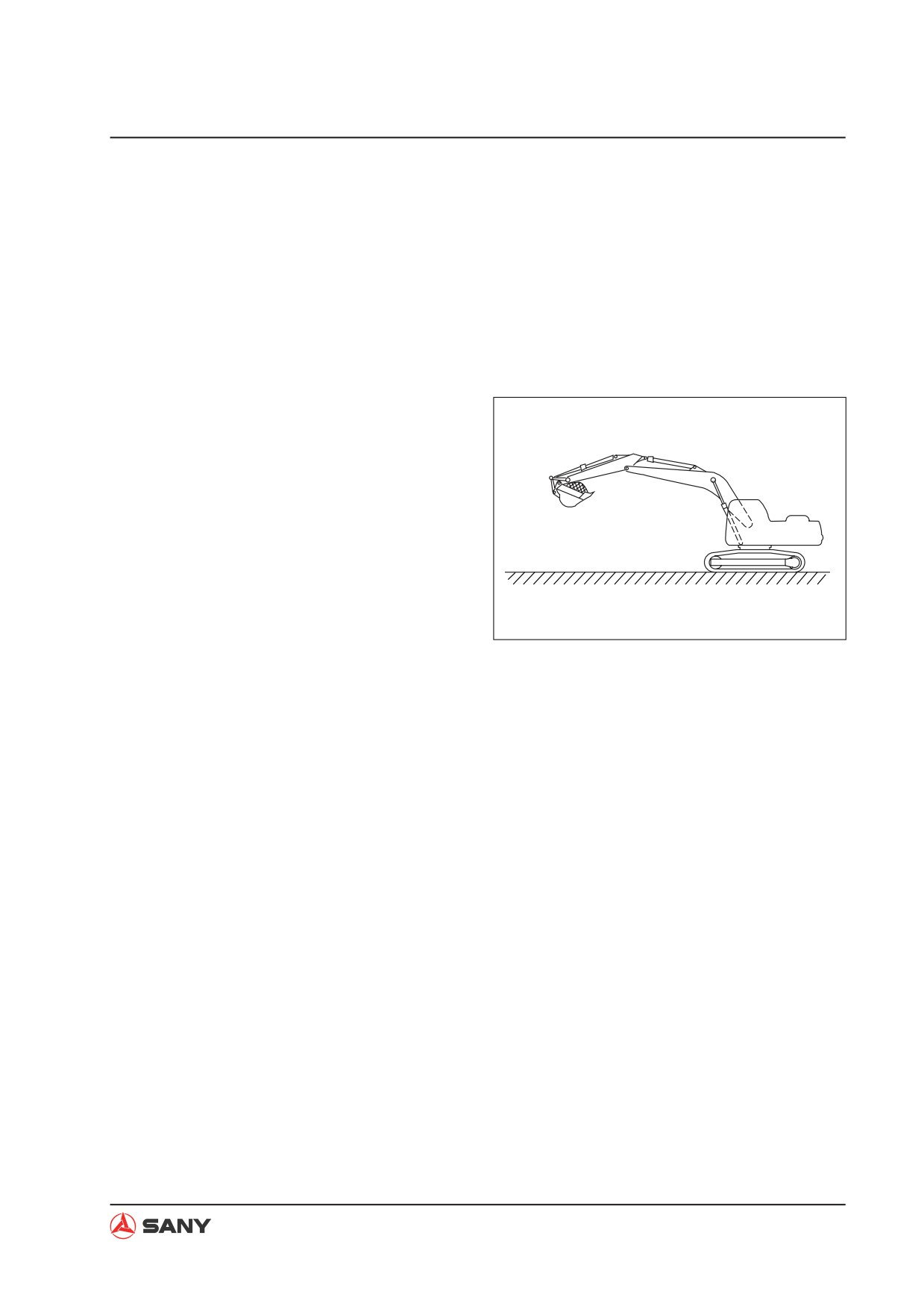
1. Boom and bucket cylinders
1) Park your machine in an attitude as
shown and stop the engine.
NOTE: Load the bucket fully with earth
or impose rated load on the bucket.
2) Operate the control levers so that the
boom is in the raising position and the
ZX215-1004033
bucket in the digging position.
Ɣ If the lowering speed rises, the prob-
lem lies in the cylinder seal. If nothing
changes, the problem lies in the control
valve.
Ɣ Operate the control levers with engine
start switch in the ON position.
Ɣ If the pressure in accumulator drops,
charge the accumulator again by run-
ning the engine for about 10 seconds.
2. Arm cylinder
6-37
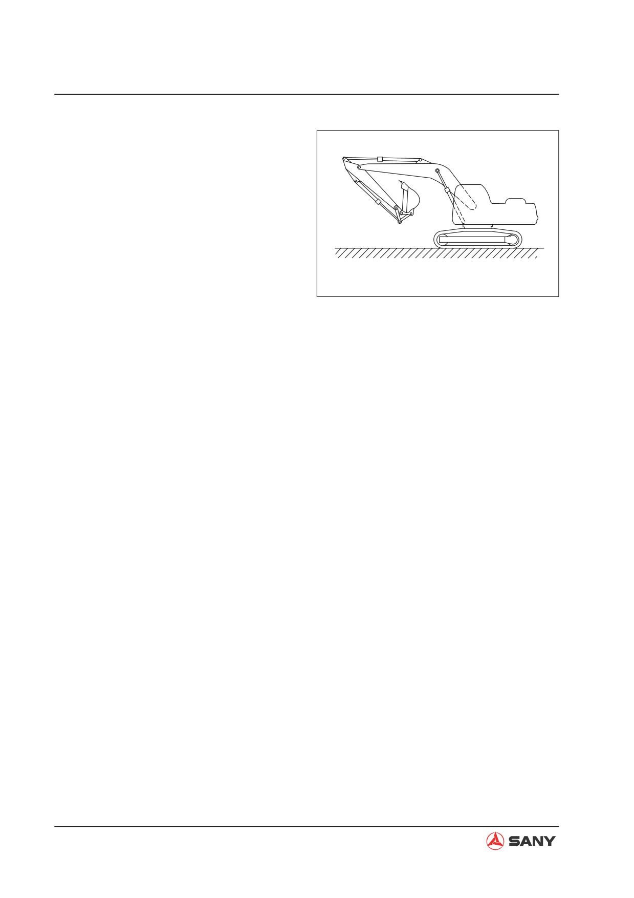
Testing and Adjusting
1) Park your machine in an attitude as
shown. The distance between the arm
cylinder and the digging stroke end is
100 mm. Stop the engine.
2) Operate the control levers in order to
place the arm in the digging position.
Ɣ If the lowering speed rises, it is failure
of the cylinder seal. If nothing changes,
it is failure of the control valve.
ZX215-1004034
Ɣ Operate the control levers with engine
start switch in the ON position.
Ɣ If the pressure in accumulator drops,
charge the accumulator again by run-
ning the engine for about 10 seconds.
[Reference]
If hydraulic drift is caused by failure of the
cylinder seal, the reason for lowering speed
increase during the above operation is de-
scribed below:
1) If the machine is set in the above position
(where the holding pressure is applied to
the bottom side), the oil leaks from the bot-
tom side to the head side. The pressure in
the head side is increased.
2) As the pressure in the head side de-
creases, the pressure in the bottom side
increases in order to keep it balanced.
This process is repeated until balance is
reached at a certain level depending on
the amount of leakage.
3) When the pressure is balanced, the lower-
ing speed decreases. If the control levers
are operated according to the above proce-
dure, the oil circuit in the head side opens
to the drain circuit (while the bottom side is
6-38