SANY Crawler Hydraulic Excavator (SY195C9, SY205C9, SY215C9, SY225C9). Shop Manual (2013) - page 19
Testing and Adjusting
closed by a check valve), and the oil flows
to the drain circuit from the head side. As a
result, the lowering speed increases.
3. Checking the pilot valve
While the pressure in the accumulator is
high, set the hydraulic lockout control in
the LOCKED/FREE position and measure
the hydraulic drift respectively.
Ɣ Operate the control levers with engine
start switch in the ON position.
Ɣ If the pressure in accumulator drops,
charge the accumulator again by run-
ning the engine for about 10 seconds.
Ɣ If there is a difference in hydraulic drift
between the LOCKED position and the
FREE position, it the failure (internal
fault) of the pilot valve.
6-39
Testing and Adjusting
6.17 Residual Pressure in Hydraulic Circuit - Release
CAUTION
Ɣ
Release the residual pressure in the hy-
draulic circuit before disconnecting the
lines between the hydraulic cylinders
or between the hydraulic motor and the
control valve.
NOTE: Even if the swing motor circuit and
the travel motor circuit are free from re-
sidual pressure, they will be influenced by
the internal pressure of hydraulic tank. The
breather valve must therefore be opened
to release pressure prior to such operation.
1.
Stop the engine, loosen the butterfly nut on
the breather valve, and press the release
button to release the pressure in hydraulic
tank.
2.
Turn the engine start switch to the ON
position and operate the control levers for
several times.
Ɣ The pilot lock valve must be energized.
Operate the control levers with the en-
gine start switch in the ON position.
Ɣ The pressure in accumulator will be
released after the control levers have
been operated 2 or 3 times.
3.
Start the engine and keep the engine run-
ning at low idle for about 10 seconds in
order to increase the pressure in accumu-
lator. Stop the engine.
4.
Repeat the above step 2 through step 3
several times.
6-40
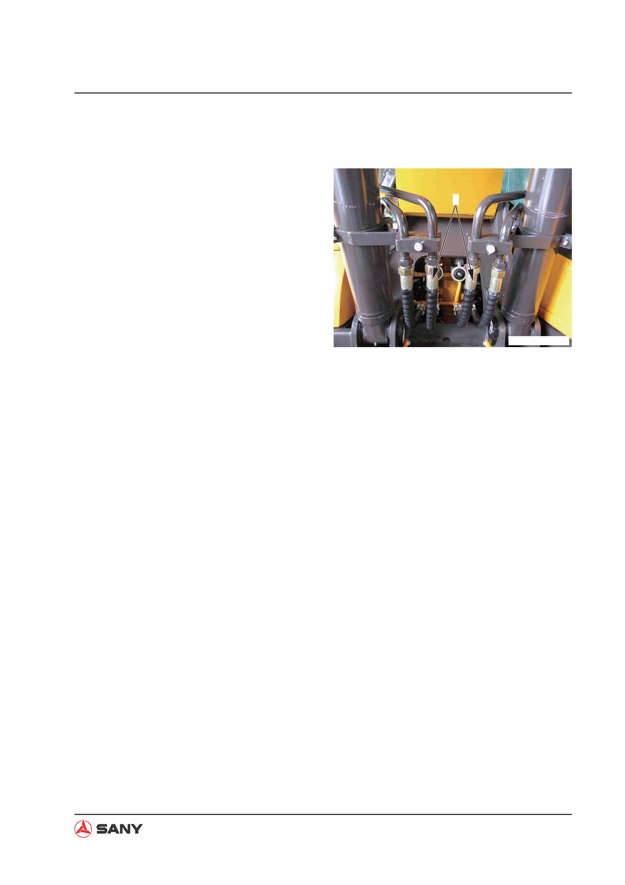
Testing and Adjusting
6.18 Oil Leakage - Measure
1.
Measure oil leakage from boom cylinder
1)
Start the engine and keep it running un-
1
til the hydraulic oil temperature is within
the operational range. Fully extend the
boom cylinder.
NOTE: Release the residual pressure
in the circuits.
See “Residual Pressure in Hydraulic
Circuit - Release” on page 6-40.
2)
Disconnect the hose (1) on the cylinder
ZXT215-1004010
head side and plug the hose end with a
cap.
NOTE: Be careful not to disconnect the
hose on the cylinder bottom side.
3)
Start the engine and apply relief pres-
sure to the bottom side of the cylinder
while the engine is running at high idle.
4)
Hold this condition for 30 seconds.
Measure oil leakage for one minute.
5)
Make sure that the machine returns to
its normal condition after measurement.
6-41
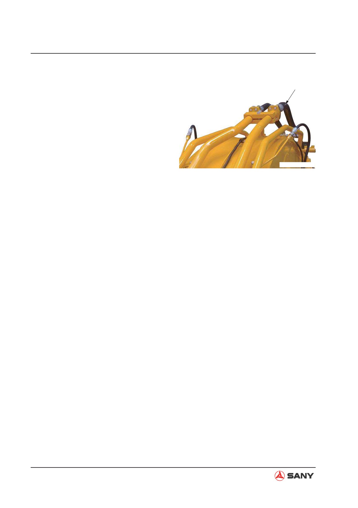
Testing and Adjusting
2.
Measure oil leakage from arm cylinder
1)
Start the engine and keep it running un-
2
til the hydraulic oil temperature is within
the operational range. Fully extend the
arm cylinder.
NOTE: Release the residual pressure
in the circuits.
See “Residual Pressure in Hydraulic
Circuit - Release” on page 6-40.
ZXT225-1104007
2)
Disconnect the hose (2) on the cylinder
head side and plug the hose end with a
cap.
NOTE: Be careful not to disconnect the
hose on the cylinder bottom side.
3)
Start the engine and apply relief pres-
sure to the bottom side of the cylinder
while the engine is running at high idle.
4)
Hold this condition for 30 seconds.
Measure oil leakage for one minute.
5)
Make sure that the machine returns to
its normal condition after measurement.
6-42
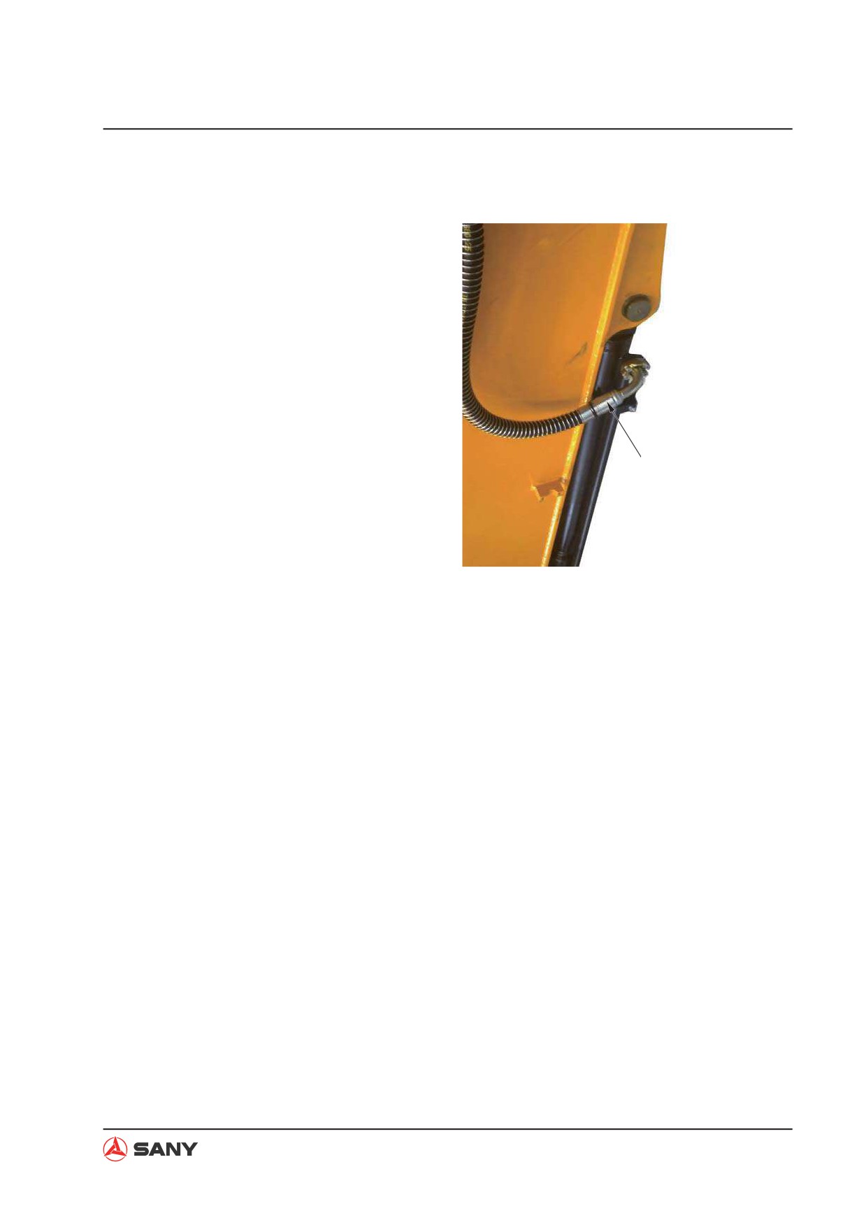
Testing and Adjusting
3.
Measure oil leakage from bucket cylin-
der
1)
Start the engine and keep it running un-
til the hydraulic oil temperature is within
the operational range. Fully extend the
bucket cylinder.
NOTE: Release the residual pressure
in the circuits.
See “Residual Pressure in Hydraulic
Circuit - Release” on page 6-40.
2)
Disconnect the hose (3) on the cylinder
head side and plug the hose end with a
3
cap.
NOTE: Be careful not to disconnect the
hose on the cylinder bottom side.
3)
Start the engine and apply relief pres-
ZXT225-1104008
sure to the bottom side of the cylinder
while the engine is running at high idle.
4)
Hold this condition for 30 seconds.
Measure oil leakage for one minute.
5)
Make sure that the machine returns to
its normal condition after measurement.
6-43
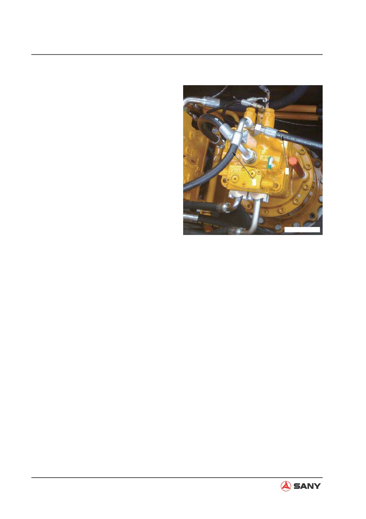
Testing and Adjusting
4.
Measure oil leakage from swing motor
1)
Fully extend the work equipment. Lower
the bucket on the ground and raise the
machine slightly. Secure machine from
rotating clockwise or counter clockwise
while testing. Stop the engine.
2)
Disconnect the hose (4) and the hose
(5). Plug the hose ends with caps.
3)
Start the engine and apply relief pres-
sure to the bottom side of the swing
5
motor while the engine is running at
4
high idle. Measure oil leakage under
this condition.
Ɣ
Hold the condition described in step 3)
for 30 seconds. Measure oil leakage for
one minute.
ZXT225-1104006
Ɣ
After the first measurement, turn the
upper structure 180°and measure the
leakage again in the same way.
4)
Make sure that the machine returns to
its normal condition after measurement.
6-44
Testing and Adjusting
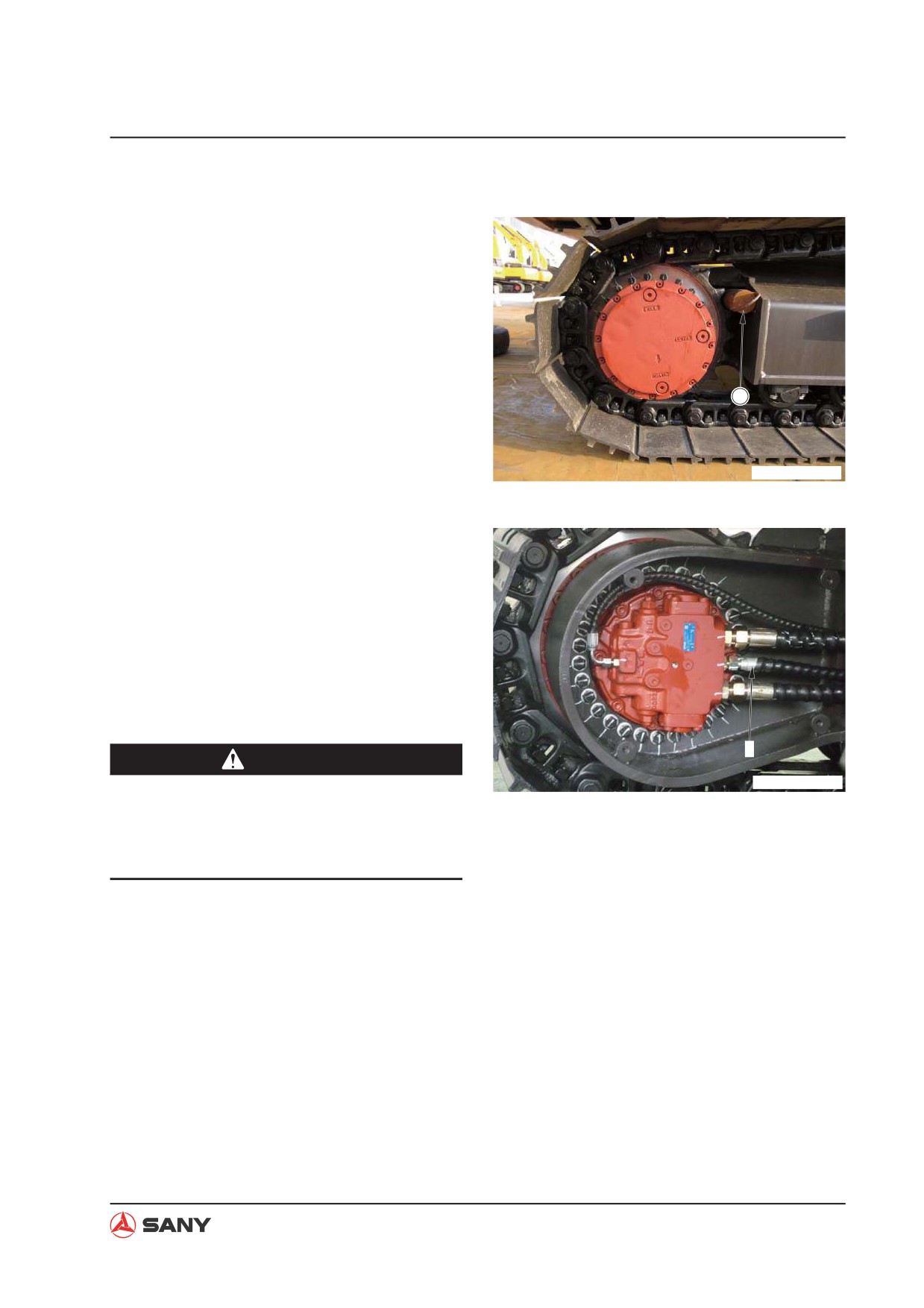
5. Measure oil leakage from travel motor
1) Remove the cover of the travel motor.
2) Start the engine and lock the travel
mechanism.
NOTE: Insert pin (1) between the
sprocket and the track frame to lock the
travel mechanism.
1
ZXT215-1004004
3) Disconnect the drain hose (6) of the
travel motor. Plug the hose end with a
cap.
4) Start the engine and apply relief pres-
sure to the bottom side of the travel
motor while the engine is running at
high idle. Measure oil leakage under
this condition.
6
WARNING
ZXT215-1004014
Ɣ
During measurement, mis-operation of
the control levers can cause serious ac-
cidents. Make sure that all signals are
given correctly.
Ɣ Hold the condition described in step 4)
for 30 seconds. Measure oil leakage for
one minute.
Ɣ Rotate the motor slightly. Change the
positions of the valve plate and the
travel motor and of the cylinder and pis-
ton. Repeat the measurement several
times.
5) Make sure that the machine returns to
its normal condition after measurement.
6-45
Testing and Adjusting
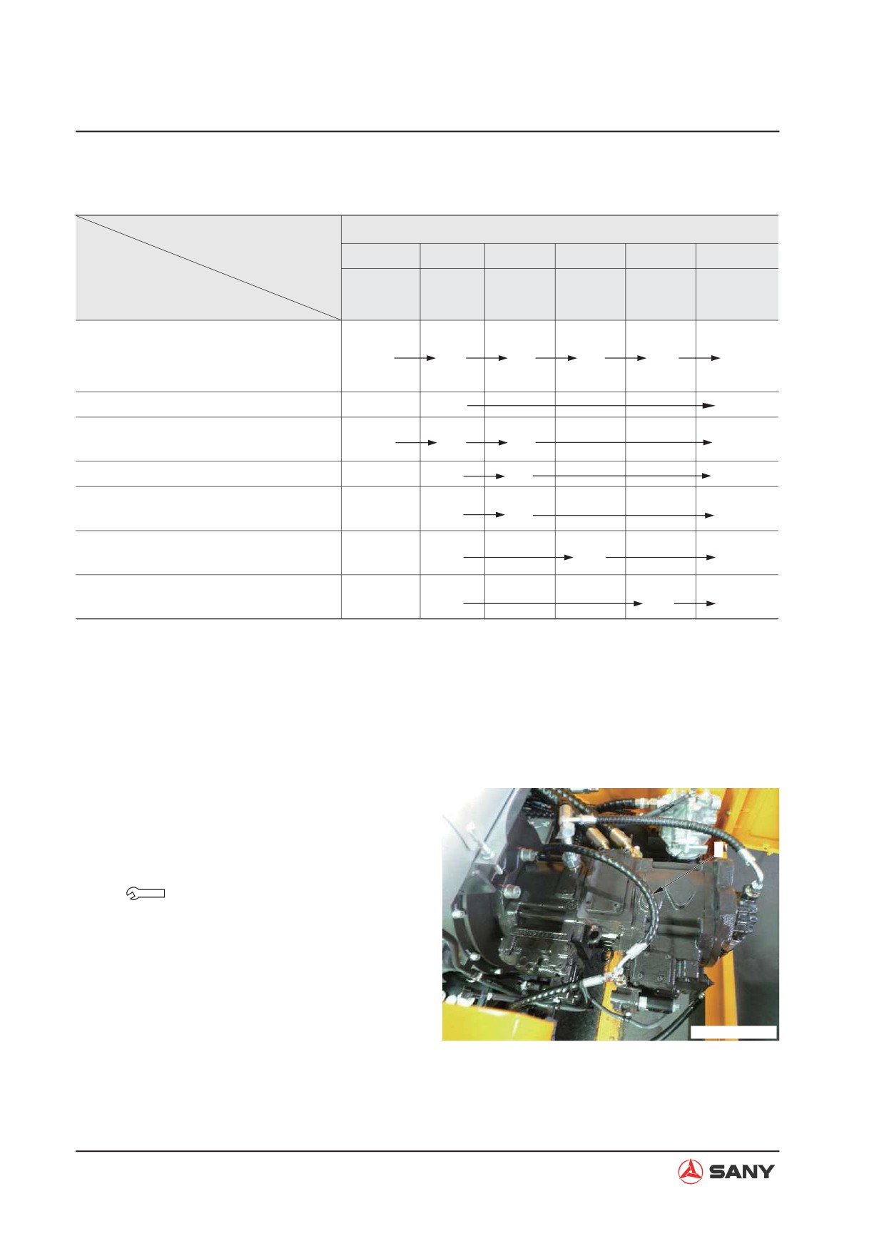
6.19 Air in Each Component - Bleed
Air bleeding procedures
Air bleeding item
1
2
3
4
5
6
Bleed air
Bleed
Bleed air
Bleed air
Starting
Starting
Contents of work
from hydrau-
air from
from swing
form travel
engine
operation
lic pump
cylinder
motor
motor
Ɣ Replacing hydraulic oil
ż
ż
ż
ż
ż
ż
Ɣ Cleaning filter element
(Note)
(Note)
Ɣ Replacing return filter element
ż
ż
Ɣ Repairing/replacing hydraulic pump
ż
ż
ż
ż
Ɣ Removing suction piping
Ɣ Repairing/replacing control valve
ż
ż
ż
Ɣ Replacing cylinder
ż
ż
ż
Ɣ Removing cylinder piping
Ɣ Replacing swing motor
ż
ż
ż
Ɣ Removing swing motor piping
Ɣ Replacing travel motor
ż
ż
ż
Ɣ Removing travel motor piping
NOTE: Bleed air from the swing motor and
travel motor only when the oil in the motor
cases is drained.
1. Bleed air from hydraulic pump
1) Loosen the air bleeder (1) and check
that oil oozes out through the air bleed-
er.
1
2) Tighten the air bleeder (1) if oil is seen.
Bleeder:
7.8~9.8 N·m{0.8~1.0 kgf·m}
NOTE: Run the engine at low idle for
10 minutes after bleeding the air ac-
cording to the above procedure.
ZXT215-1004015
6-46
Testing and Adjusting
2.
Bleed air from hydraulic cylinder
1)
Start the engine and keep the engine
running at low idle for 5 minutes.
2)
Raise or lower the boom 4 or 5 times
with the engine running at low idle.
NOTE: Be careful not to apply relief
pressure. Stop the piston when the rod
is about 100 mm before stroke end.
3)
Repeat step 2) with the engine running
at high idle.
4)
While running the engine at low idle,
move the piston rod to the stroke end
and apply relief pressure.
5)
Bleed air from arm cylinder and bucket
cylinder by performing step 2) through
step 4).
NOTE: When a new cylinder is in-
stalled for replacement, bleed the air
from the new cylinder before mounting
it to the work equipment. Especially the
boom cylinder, once mounted to the
work equipment, its piston rod is un-
able to reach its stroke end in lowering
operation. Therefore, the air must be
bled from the boom cylinder before it is
mounted to the work equipment.
3. Bleed air from swing motor
1) Start the engine and run the engine at
low idle.
2) Bleed air from the swing motor by turn-
ing the upper structure slowly.
6-47
Testing and Adjusting
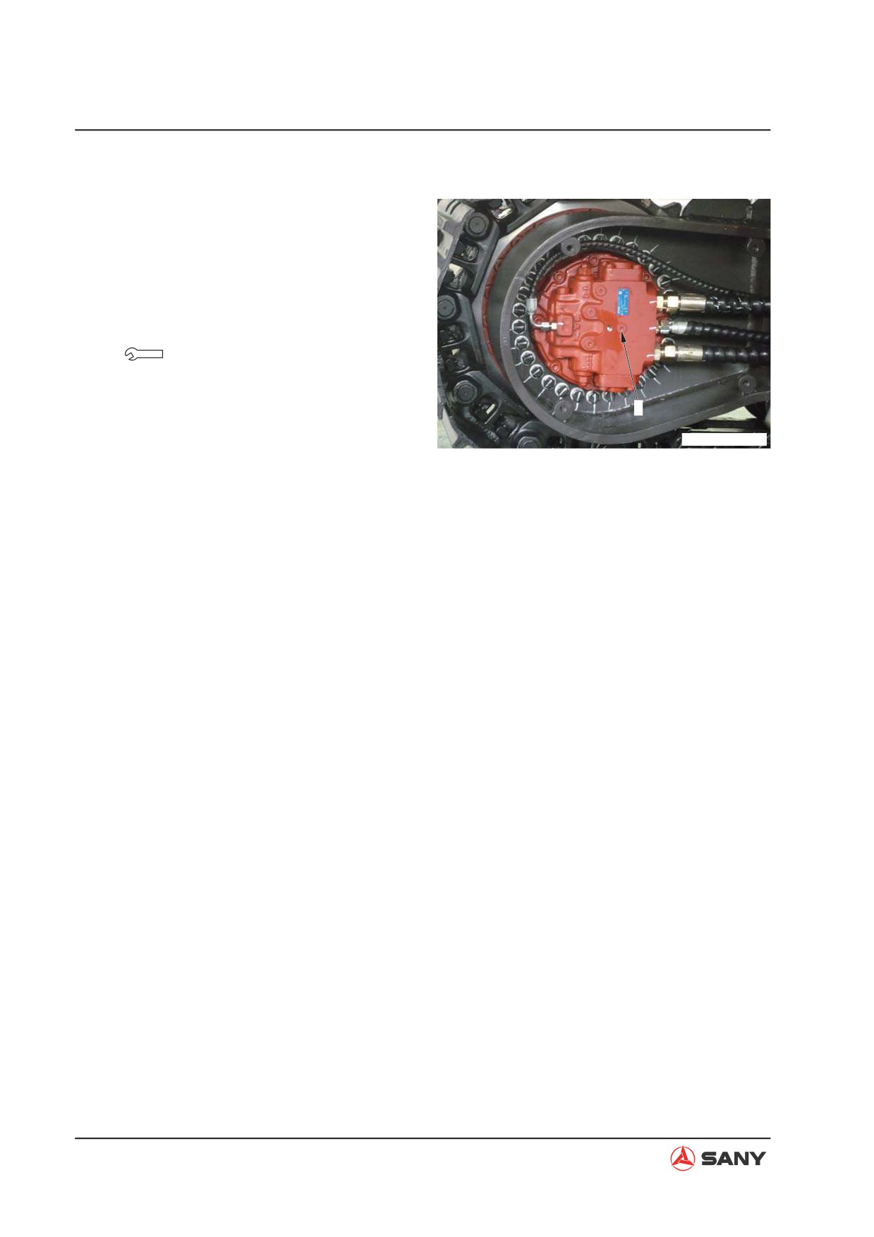
4. Bleed air from travel motor
1) Start the engine and run the engine at
low idle.
2) Loosen the bleeder (2) and check that
oil oozes out through the air bleeder.
3) Tighten the air bleeder (2) if oil is seen.
Bleeder:
27.5~35.3 N·m{2.8~3.6 kgf·m}
2
ZXT215-1004016
6-48
Testing and Adjusting
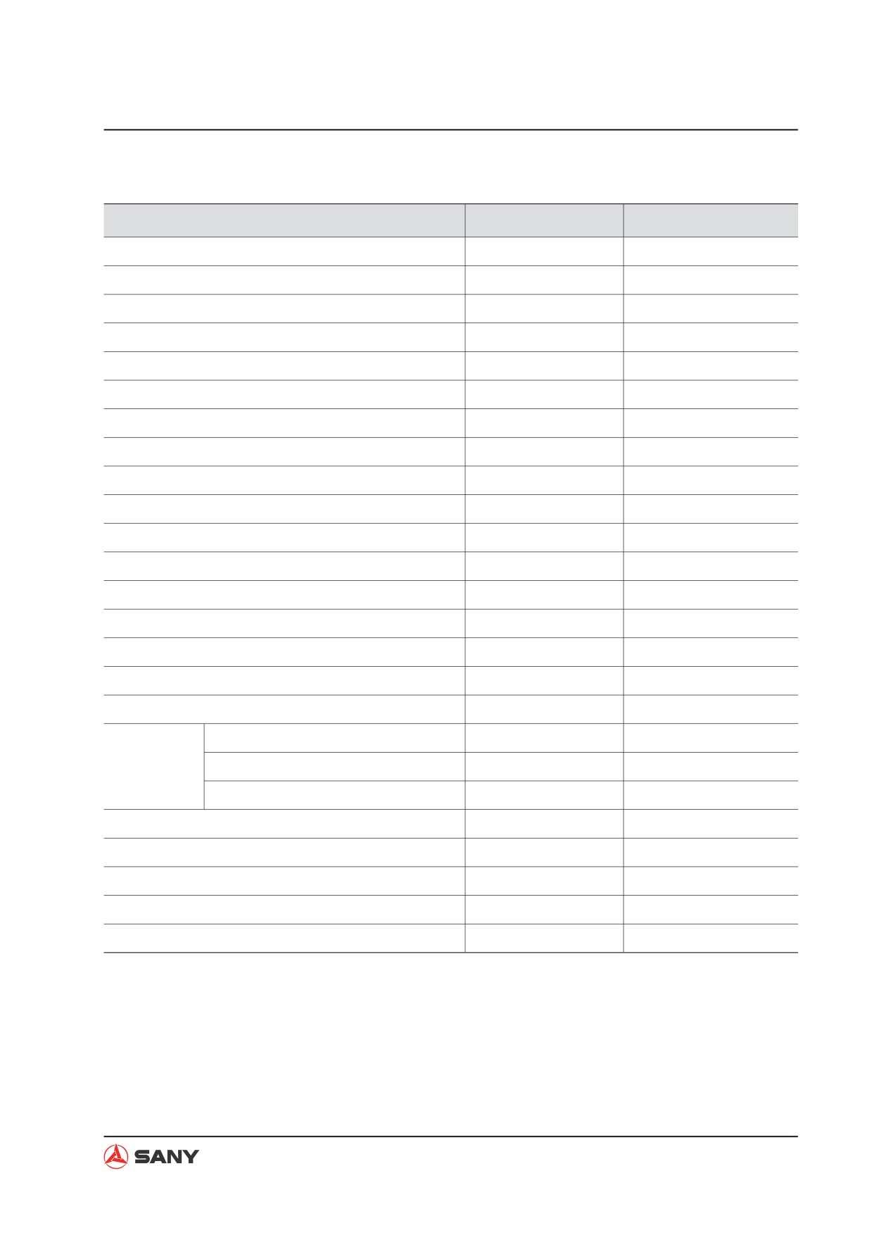
Table of monitored items
Monitored Item
Unit
Remark
Controller Mode Selection
Graph
High/Low Travel Speed Selection
Graph
Auto Idle Selection
Graph
Engine Speed
r / min
Pressure - Front pump
Kg
Pressure - Rear pump
Kg
Current - Proportional Valve (Solenoid, Front pump)
mA
Current - Proportional Valve (Solenoid, Rear pump)
mA
Pilot Pressure - Boom Raise
Kg
Pilot Pressure - Boom Lower
Kg
Pilot Pressure - Arm In
Kg
Pilot Pressure - Arm Out
Kg
Pilot Pressure - Bucket Curl
Kg
Pilot Pressure - Bucket Dump
Kg
Pilot Pressure - Swing
Kg
Pilot Pressure - Travel Left
Kg
Pilot Pressure - Travel Right
Kg
Bucket Confluence
ON / OFF
Solenoid
Swing Priority
ON / OFF
Valve 1
Hi/Lo Speed Switching
ON / OFF
Voltage - Fuel Control Dial
V
Voltage - Motor Position
V
Temperature - Engine Coolant
°C
Gauge reading
Temperature - Hydraulic oil
°C
Gauge reading
Pressure - Engine Oil
KPa
6-49
Troubleshooting
Troubleshooting
7 Troubleshooting
7.1 Points to Remember When Troubleshooting
7-3
7.2 Troubleshooting Procedures
7-5
7.3 Connector Location and Electrical Circuit Diagram
7-8
7.3.1 Connector location layout
7-12
7.3.2 Electrical element circuit diagram (cab circuit)
7-18
7.3.3 Electrical control circuit diagram (engine circuit)
7-20
7.3.4 Electrical control circuit diagram (sensor and solenoid valve circuit)
7-22
7.3.5 SWP type connector
7-23
7.3.6 A/AMP type connector
7-24
7.3.7 DT type connector
7-25
7.4 Failure Symptoms and Troubleshooting Codes
7-26
7.5 Troubleshooting with an Event Code
7-28
7.6 Troubleshooting of Electrical System (E - Mode)
7-63
7.7 Troubleshooting of Hydraulic and Mechanical Systems (H - Mode)
7-93
7-1
Troubleshooting
WARNING
Read and understand all safety precau-
tions and instructions in this manual be-
fore reading any other manuals provided
with this machine and before operating or
servicing the machine. Also read the safety
information on machine decals before per-
forming any operations. Failure to do so
can cause machine damage, personal in-
jury or death.
7-2
Troubleshooting
7 TROUBLESHOOTING
7.1 Points to Remember When Troubleshooting
Ɣ Stop the machine in a level ground, and check that lock pins, blocks, and parking brake are
securely fitted.
Ɣ When carrying out the operation with two or more workers, keep strictly to the agreed signals,
and do not allow any unauthorized person to come near.
Ɣ If the radiator cap is removed when the engine is hot. Hot coolant may spurt out and cause
burns, so wait for the engine to cool down before starting troubleshooting.
Ɣ Be extremely careful not to touch any hot parts or to get caught in any rotating parts.
Ɣ When disconnecting wiring, always disconnect the negative (-) terminal of the battery first.
Ɣ When removing the plug or cap from a location which is under pressure from oil, water, or air,
always release the internal pressure first. When installing measuring equipment, be sure to
connect it properly.
The aim of troubleshooting is to pinpoint the
It will also cause a waste of man-hours,
basic cause of the failure, to carry out repairs
parts, or oil or grease, and at the same
swiftly, and to prevent reoccurrence of the fail-
time, will also lose the confidence of the
ure.
user or operator.
When carrying out troubleshooting, important
For this reason, when carrying out
point is to understand the structure and func-
troubleshooting, it is necessary to carry out
tion.
thorough prior investigation and to carry
out troubleshooting in accordance with the
However, a short cut to effective troubleshoot-
fixed procedure.
ing is to ask the operator various questions
to form some idea of possible causes of the
2.
Points to ask user or operator:
failure that would produce the reported symp-
1) Have any other problems occurred apart
toms.
from the problem that has been reported?
1. When carrying out troubleshooting, do not
2) Was there anything strange about the
hurry to disassemble the components.
machine before the failure occurred?
If components are disassembled immedi-
3) Did the failure occur suddenly, or were
ately any failure occurs:
there problems with the machine condition
Ɣ Parts that have no connection with the
before this?
failure or other unnecessary parts will
4) Under what conditions did the failure oc-
be disassembled.
cur?
Ɣ It will become impossible to find the
5) Had any repairs been carried out before
cause of the failure.
7-3
Troubleshooting
the failure? When were these repairs car-
5.
Troubleshooting
ried out?
Ɣ
Use the results of the investigation and
6) Has the same kind of failure occurred be-
inspection in Items 2 - 4 to narrow down
fore?
the causes of failure, then use the trouble-
shooting flowchart to locate the position of
3.
Check before troubleshooting
the failure exactly.
1) Check the oil level.
Ɣ
The basic procedure for troubleshooting is
as follows.
2) Check for any external leakage of oil from
the piping or hydraulic equipment.
1) Start from the simple points.
3) Check the travel of the control levers.
2) Start from the most likely points.
4) Check the stroke of the control valve spool.
3) Investigate other related parts or informa-
tion.
5) Other maintenance items can be checked
externally, so check any item that is con-
6.
Measures to remove root cause of failure
sidered to be necessary.
Ɣ
Even if the failure is repaired, if the root
4.
Confirming failure
cause of the failure is not repaired, the
same failure will occur again. To prevent
Ɣ
Confirm the extent of the failure yourself,
this, always investigate why the problem
and judge whether to handle it as a real
occurred. Then, remove the root cause.
failure or as a problem with the method of
operation, etc.
NOTE: When operating the machine to
reenact the troubleshooting symptoms, do
not carry out any investigation or measure-
ment that may make the problem worse.
7-4
Troubleshooting
7.2 Troubleshooting Procedures
If some phenomenon occurs on a machine that looks like a failure, identify the corresponding
troubleshooting No. and proceed to the explanations for diagnosis.
Follow six steps listed below to diagnose and analyze for troubleshooting, and find the causes
and work out the corresponding methods.
1. Read related technical manuals in detail.
d. What kind of trouble did machine have
Have a knowledge of related system,
before?
principle of operation, and structure,
For example: Which parts have been
function and technical specification of
repaired or replaced?
parts.
e. What has been done after troubles take
2. Ask operator
place and how about the reaction?
Before checking, ask related person, i.e.
f. Will the trouble reoccur? Does the trou-
the operator for all information about the
ble occur regularly?
failure.
3.
Check before starting
a. Current working condition of machine
(Whether machine is operated prop-
Before starting troubleshooting, check
erly).
the operator's records on operation,
maintenance and service of the machine.
b. When troubles are found and what kind
Understand whether related personnel has
of operation does machine perform at
done wrong in operation, maintenance and
that time?
service. Check for wrong operation and
c. Development of troubles (Whether
maintenance at the same time.
troubles are becoming severer or occur
for the first time.)
7-5
Troubleshooting
Item
Criterion
Remedy
1. Check fuel level and type of fuel
—
Add fuel
2. Check for impurities in fuel
—
Clean, drain
3. Check hydraulic oil level
—
Add oil
4. Check hydraulic oil strainer
—
Clean, drain
5. Check swing drive oil level
—
Add oil
6. Check engine oil level (in oil pan)
—
Add oil
7. Check coolant level
—
Add water
8. Check dust indicator for clogging
—
Clean or replace
9. Check hydraulic filter
—
Replace
10. Check final drive oil level
—
Add oil
—
1. Check for looseness, corrosion of battery terminal and
Tighten or replace
—
wiring
—
2. Check for looseness, corrosion of alternator terminal
Tighten or replace
and wiring
3. Check for looseness, corrosion of start motor terminal
Tighten or replace
and wiring
1. Check for abnormal noise and smell
—
Repair
2. Check for oil leakage
—
Repair
3. Bleeding air
—
Bleed air
1. Check battery voltage (with engine stopped)
20-30V
Replace
2. Check electrolyte level
—
Add or replace
3. Check for discolored, burnt, exposed wiring
—
Replace
4. Check for missing wiring clips and hanging wiring
—
Repair
5. Check for wet wires (esp. wet connectors or terminals)
—
Disconnect con-
6. Check for blown or corroded fuses
nector and dry
7. Check alternator voltage (with engine speed at middle
—
or higher)
After running for
Replace
8. Check operating sound of battery relay (when start
several minutes:
Replace
switch is turned ON or OFF)
27.5~ 29.5V
Replace
—
7-6
Troubleshooting
4. Operate machine by yourself (trial run)
Ɣ Failure codes may not indicate machine
trouble. Temporary electrical failure can oc-
Confirming that the third item above is
cur in controller memory, such as low bat-
normal, run startup check on the machine
tery output voltage, or open circuit in switch
to determine the cause of failure. If the
or sensor. Therefore, make repeated trials
failure cannot be determined, turn off the
to erase the accumulated failure codes
engine and get more information from the
from the controller memory and confirm
operator.
whether the failure codes are displayed af-
ter repeated trials. That is to say, "reoccur-
5. Perform troubleshooting
rence" of this trouble is possible.
Conduct deep analysis and determine the
6. Find out possible causes
cause of trouble according to the symp-
toms of the machine and the information
Before making a conclusion, check the
displayed on the monitor.
most possible causes again and try to de-
termine the root causes of troubles. Make
Remark:
a feasible repair scheme according to your
Ɣ Never disconnect harness and hydraulic
conclusion.
lines when the engine is running. Oil and
water under high pressure and high tem-
perature may squirt and cause personal
injuries. Shut off then engine when discon-
necting the harness and hydraulic lines.
7-7
Troubleshooting
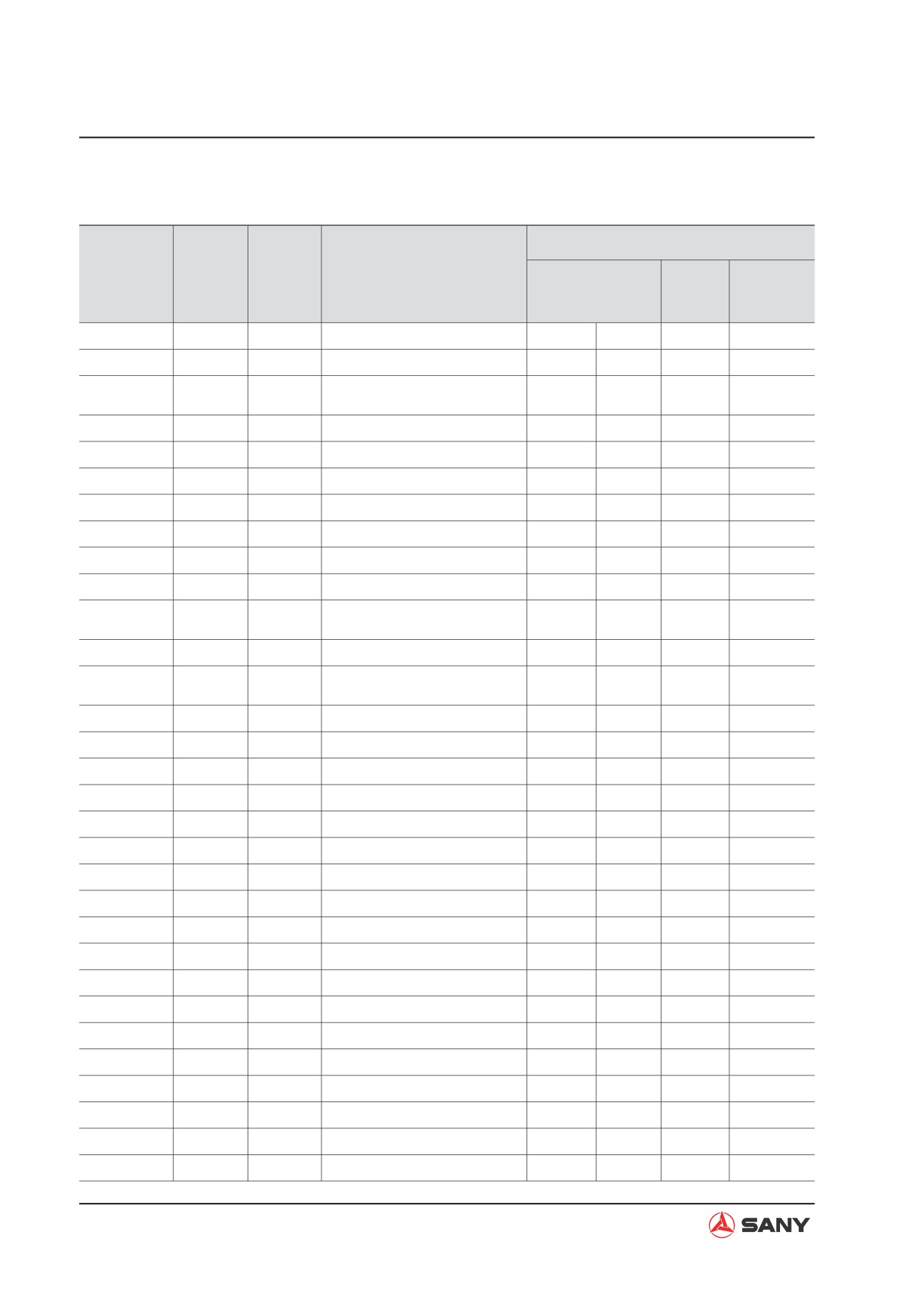
7.3 Connector Location and Electrical Circuit Diagram
Location
Connec-
No. of
Sensor,
Type
Name of device
Cab
Engine
tor No.
pin
Layout
solenoid
circuit
circuit
circuit
T-101
Terminal
1
Battery relay coil (positive)
M-2
D-1
T-102
Terminal
1
Battery relay coil (negative)
M-2
D-1
Battery relay contact (out-
T-103
Terminal
1
M-2
D-1
put)
T-104
Terminal
1
Battery relay contact (input)
M-2
D-1
T-106
Terminal
1
Starting motor (B terminal)
J-6
L-3
T-107
Terminal
1
Alternator (B terminal)
K-6
L-5
T-108
Terminal
1
Preheating fuse (21#)
M-2
G-9
T-109
Terminal
1
Preheating fuse (17#)
M-2
G-9
T-110
Terminal
1
Body grounding
M-1
B-1
T-111
Terminal
1
Body grounding
K-6
Preheating resistance wire
T-112
Terminal
1
J-7
H-9
terminal
T-115
Terminal
1
Starting motor grounding
J-6
L-3
Body grounding (at the sides
T-119
Terminal
1
M-1
B-9
of battery)
T-201
Terminal
1
Body grounding
X-6
T-202
Terminal
1
Body grounding
X-6
K5
R
5
Horn relay
X-6
H-9
K6
R
5
Lamp relay
X-6
I-9
K8
R
5
Top lamp relay
X-6
J-9
K7
R
5
Parking relay
X-6
J-8
KB
—
5
Battery relay
M-2
D-1
K3
R
5
Starting relay
X-6
L-4
KH
—
5
Preheating relay
Y-6
G-9
K10
R
5
Pilot valve relay
X-6
K-1
CN-106F
A
2
Junction connector
W-6
J-2
CN-142M
D
12
Intermediate connector
W-6
C-9
CN-131M
D
12
Intermediate connector
R-5
C-9
CN-302F
A
3
Intermediate connector
R-6
D-9
CN-301M
S
6
Intermediate connector
R-6
F-9
CN-132F
D
12
Intermediate connector
R-5
C-5
CN-1-110
D
6
Intermediate connector
AB-4
K-5
CN-121F
D
12
Intermediate connector
W-6
D-8
7-8
Troubleshooting
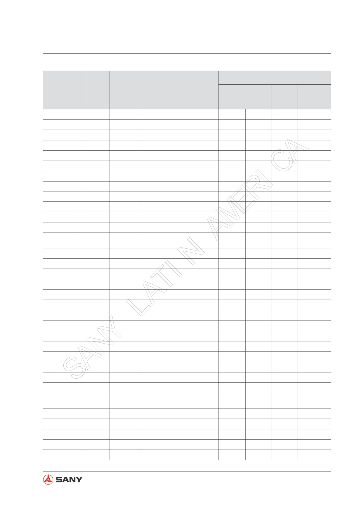
Location
Connec-
No. of
Sensor,
Type
Name of device
Cab
Engine
tor No.
pin
Layout
solenoid
circuit
circuit
circuit
CN-241M
D
12
Intermediate connector
W-6
F-8
CN-1-112
3
3
Intermediate connector
W-6
C-9
CN-1-111
D
8
Intermediate connector
W-6
C-9
CN-7-705
D
12
Monitor panel
P-5
D-9
CN-801F
H
6
Intermediate connector
J-7
K-8
CN-445M
S
6
Intermediate connector
I-7
F-3
CN-204F
A
2
Intermediate connector
X-6
C-8
CN-412F
A
3
Intermediate connector
X-6
C-8
CN-112M
A
2
Washing motor
K-5
K-4
CN-102M
A
2
Platform lamp
E-5
K-2
CN-104M
A
2
Boom lamp (left)
E-7
K-1
CN-105M
A
2
Boom lamp (right)
E-7
K-2
Hydraulic oil temperature
CN-113M
A
2
I-7
F-9
sensor
CN-101M
S
1
Fuel level sensor
F-6
F-9
CN-152M
A
2
Intermediate connector
W-6
F-8
CN-613F
L
6
Safety relay
X-6
K-7
CN-661F
S
16
Intermediate connector
W-6
I-8
CN-161M
S
16
Intermediate connector
W-6
CN-115M
DF
3
Main pressure sensor (front)
I-7
F-4
CN-116M
DF
3
Main pressure sensor (rear)
I-7
F-4
CN-128M
DF
3
Arm-in pilot sensor
I-6
F-5
CN-122M
DF
3
Arm out pilot sensor
I-6
F-4
CN-126M
DF
3
Boom-up pilot sensor
I-6
F-5
CN-125M
DF
3
Boom-down pilot sensor
I-6
F-6
CN-124M
DF
3
Bucket-curl pilot sensor
I-6
F-6
CN-127M
DF
3
Bucket-dump pilot sensor
I-6
F-6
CN-123M
DF
3
Swing pilot sensor
I-6
F-7
CN-120M
DF
3
Travel pilot sensor (left)
I-6
F-7
CN-121M
DF
3
Travel pilot sensor (right)
I-6
F-8
CN-448M
S
2
Speed sensor
I-7
F-9
CN-307M
H
8
Top lamp switch
R-5
C-3
CN-303M
H
8
Work lamp switch
R-6
C-2
CN-305M
H
8
Washer switch
R-6
C-2
7-9