SANY Crawler Hydraulic Excavator (SY195C9, SY205C9, SY215C9, SY225C9). Shop Manual (2013) - page 12
Structure and Function
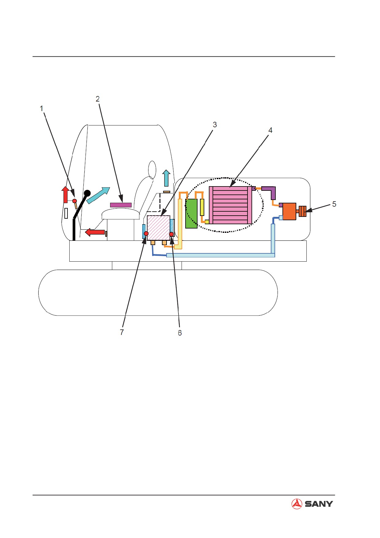
4.7.1 A/C components layout drawing
ZX215-1002138
1) Sunlight sensor
5) Compressor
2) Control panel
6) Fresh air sensor
3) Air conditioning unit
7) Recirculated air sensor
4) Condenser
4-130
Structure and Function
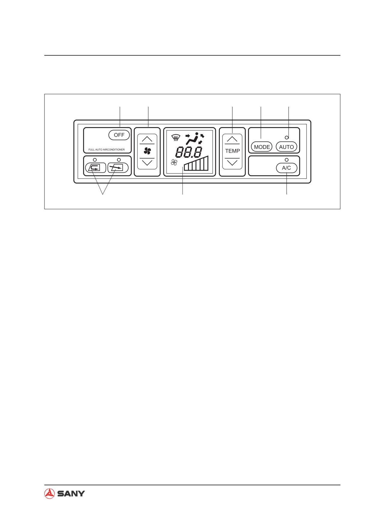
4.7.2 Control panel
1
2
3
4
5
6
7
8
CZ205-1203020G
1) OFF switch
5) Auto mode switch
2) Fan speed control switch
6) Air circulation control switch
3) Temperature control switch
7) LCD display
4) Air outlet mode switch
8) A/C switch
4-131
Structure and Function
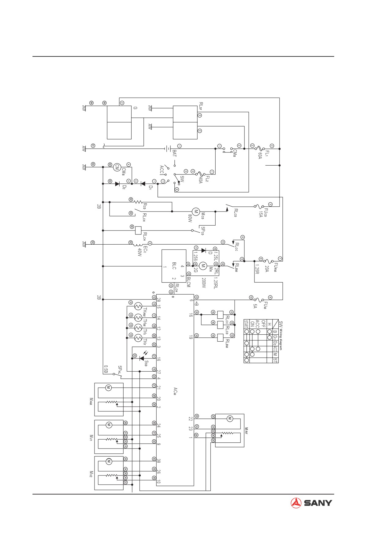
4.7.3 Circuit diagram
1.25B
1.25B
0.85B
2B
0.50
1.25R
FFE
REC
Vz
Pt
GND
4-132
Structure and Function
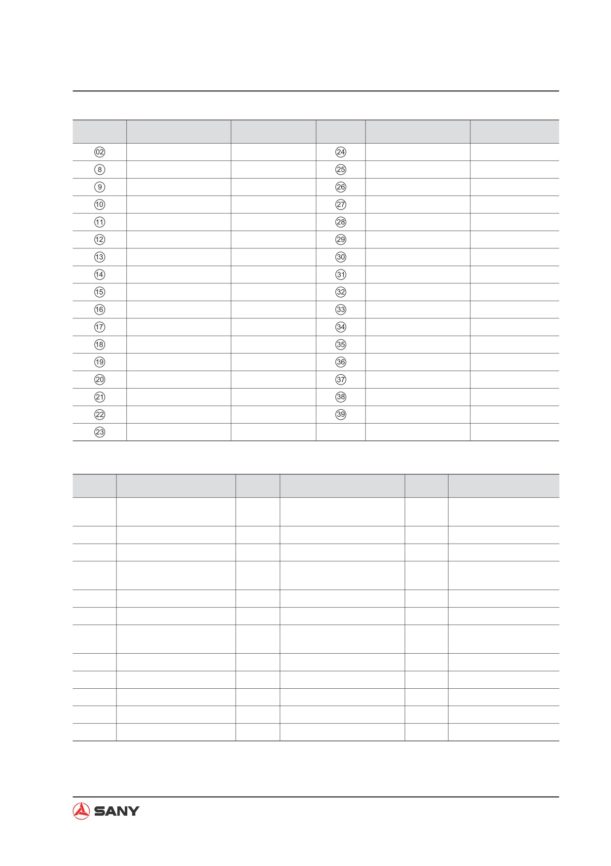
Wire No.
Diameter/Color code
Wire color
Wire No.
Diameter/Color code
Wire color
B
Black
0.5VW
Violet+white
Br(R)
Brown
0.5YB
Yellow+black
0.85W
White
0.5WO
White+orange
RL
Red+blue
0.5PB
Pink+black
G
Green
0.5VR
Violet+red
0.5BL
Black+blue
0.5BG
Black+green
0.5R
Red+blue
0.5WY
White+yellow
0.5Y
Yellow
0.5WR
White+red
0.5BR
Black+red
0.5BrW
Brown+white
0.5BrY
Brown+yellow
0.5GO
Green+orange
0.5BY
Black+yellow
0.5Sb
Sky blue
0.5GW
Green+white
0.5OW
Orange+white
0.5LO
Blue+orange
1.25V
Violet
0.5PG
Pink+green
1.25RG
Red+green
0.5RY
Red+yellow
1.25RW
Red+orange
0.5BW
Black+white
0.85GL
Green+Blue
0.5LgR
Light green+red
Code
Name
Code
Name
Code
Name
Condenser high speed
ACM
A/C amplifier
FUCD
Condenser fuse
RLCH
relay
BAT
Battery
FUM
A/C main fuse
RLSF
Protective relay
BLC
Speed regulating resistor
G
Alternator
SSD
Sunlight sensor
Condenser pressure
CMB
Battery relay
MAM
A/M servo motor
SPCD
switch
D
Diode
MB
Blower motor
SPHL
HI/LO pressure switch
D1
Diode 1
MCD
Condenser motor
SW
Switcher
Internal/External air servo
D2
Diode 2
MRF
THAM
External air thermistor
motor
ECC
Compressor clutch
MV1
Air outlet servo motor
THF
Anti-frosting thermistor
FL1
Fuse
MV2
FRONT outlet servo motor
THI
Internal air thermistor
FL2
Fuse
RCD
Condenser resistor
THW
Water temp. thermistor
FUBM
Blower fuse
RLBM
Blower main relay
RLCC
Compressor relay
RLCD
Condenser relay
4-133
Structure and Function
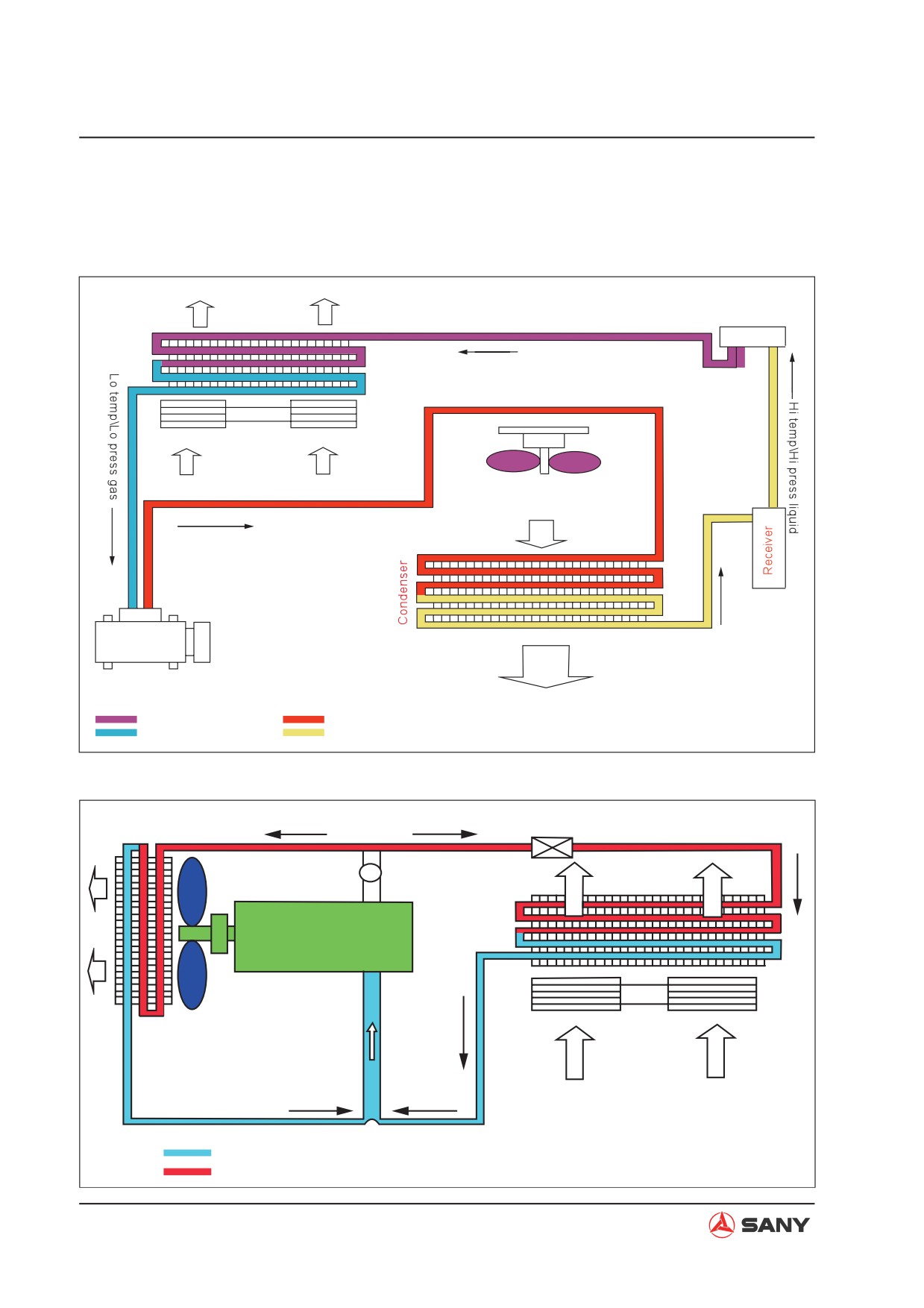
4.7.4 Refrigeration principle
4.7.4.1 Refrigeration cycle diagram
Cool air
Expansion valve
Lo temp\Lo press liquid (Mist)
Evaporator
Cooling fan
Blower
Air in cab
Out side fresh air
Hi-temp hi-pres gas
Lo-pres.
Hi-pres.
side
side
Compressor
Hot air
Lo-pressure portion
Hi-pressure portion
ZX215-1002141
4.7.4.2 Heating cycle diagram
Radiator
Water valve control
Water pump
Hot air
Engine
Blower motor
Internal air
Low tempr water
High temp water
ZX215-1002142
4-134
Structure and Function
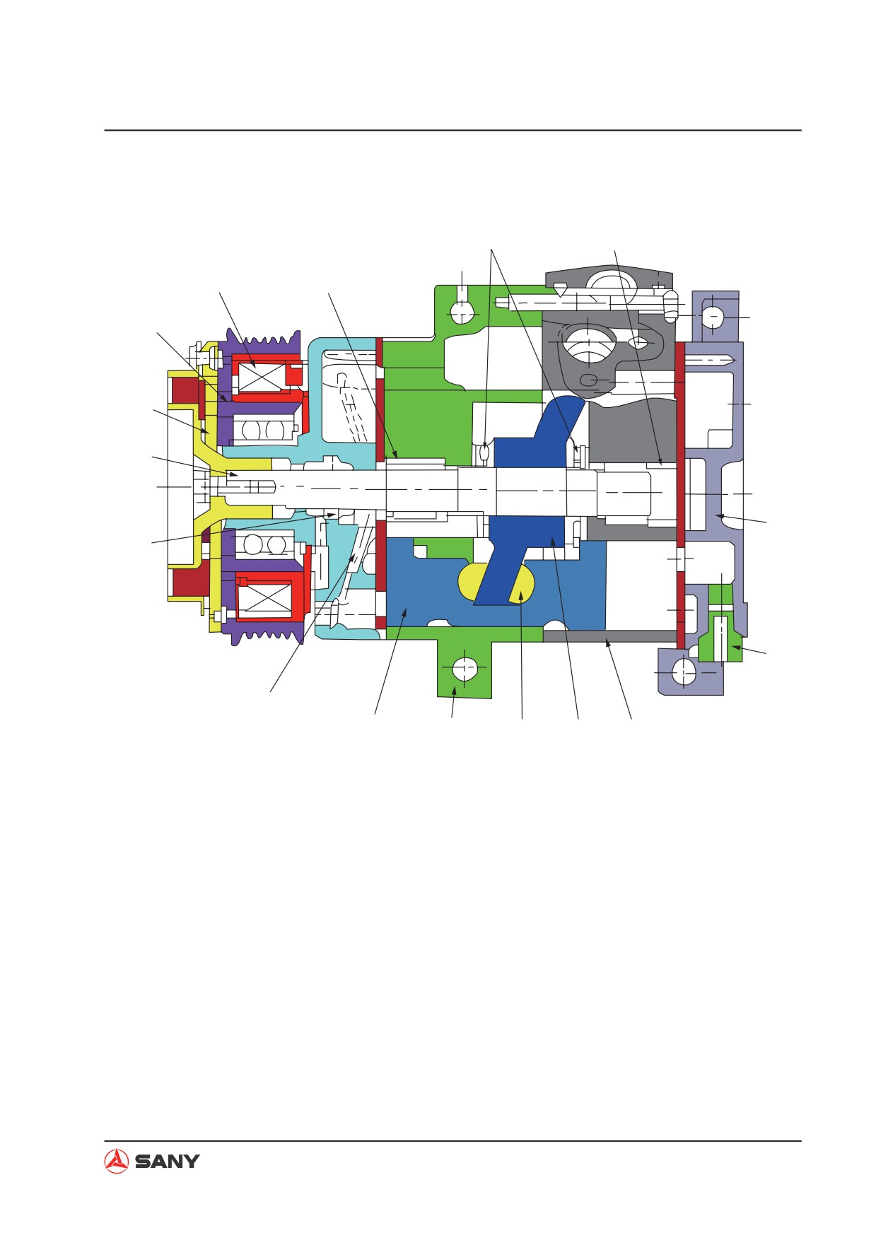
4.7.5 Compressor
3
4
1
2
16
15
14
5
13
6
12
11
10
9
8
7
ZX215-1002143
1) Stator
9) Slipper
2) Front radial bearing
10) Front cylinder block
3) Thrust bearing
11) Piston
4) Front radial bearing
12) Front cylinder head
5) Rear cylinder head
13) Shaft seal
6) Safety valve
14) Main shaft
7) Rear cylinder block
15) Hub
8) Swash plate
16) Rotor
4-135
Structure and Function
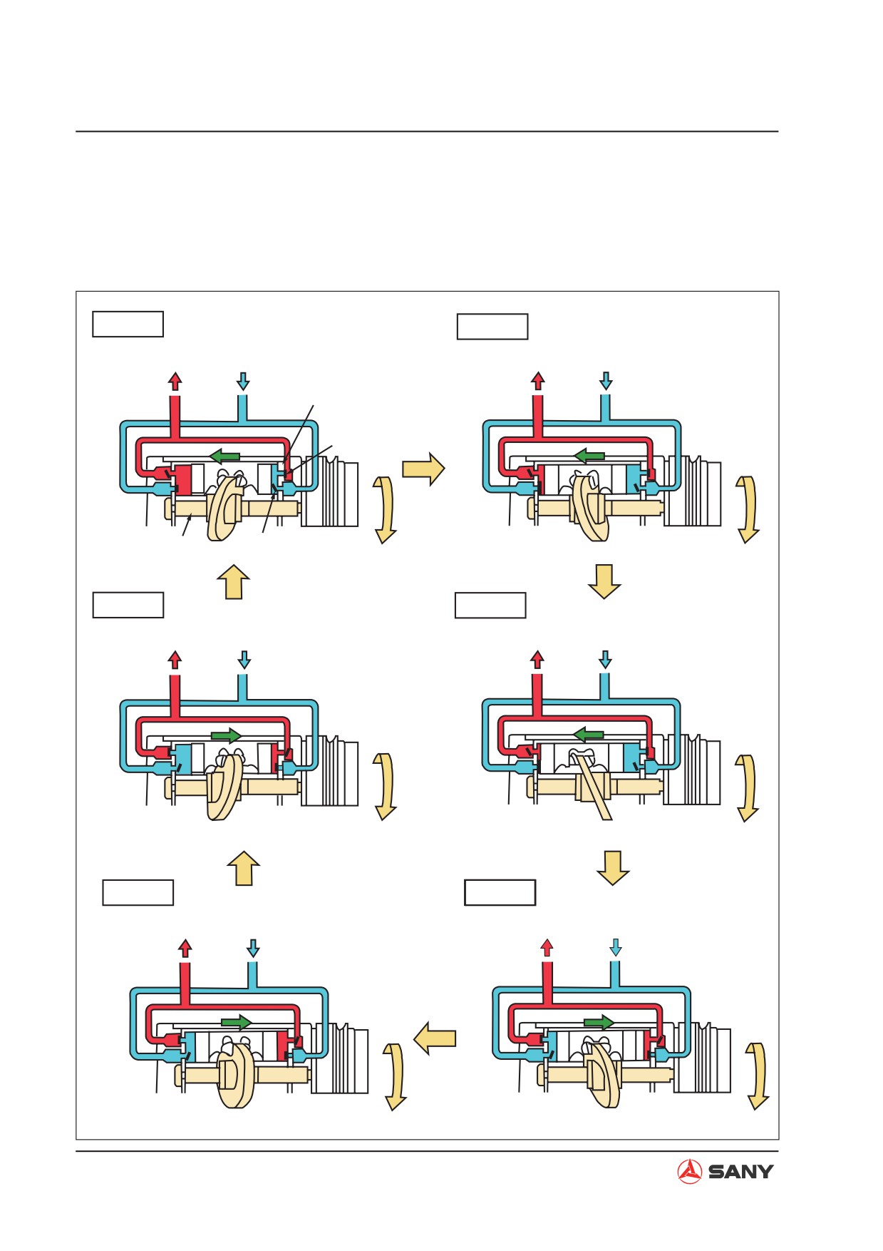
Operating principle
Compressor type: 10S15C. This compres-
back and forth and transforms the refrigerant
sor has 5 plungers in total with a piston on
sucked from the evaporator from low tempera-
both sides of each plunger. The rotation of
ture and low pressure gas state to high tem-
the swash plate drives the pistons to move
perature and high pressure state.
Process 1
Process 2
HI press.end pipe LO press.end pipe
HI press.end pipe LO press.end pipe
Valve plate
Outlet valve disc
Main shaft and swash plate
Intlet valve disc
Process 6
Process 3
HI press.end pipe
LO press.end pipe
HI press.end pipe LO press.end pipe
Process 5
Process 4
HI press.end pipe
LO press.end pipe
HI press.end pipe LO press.end pipe
ZX215-1002144
4-136
Structure and Function
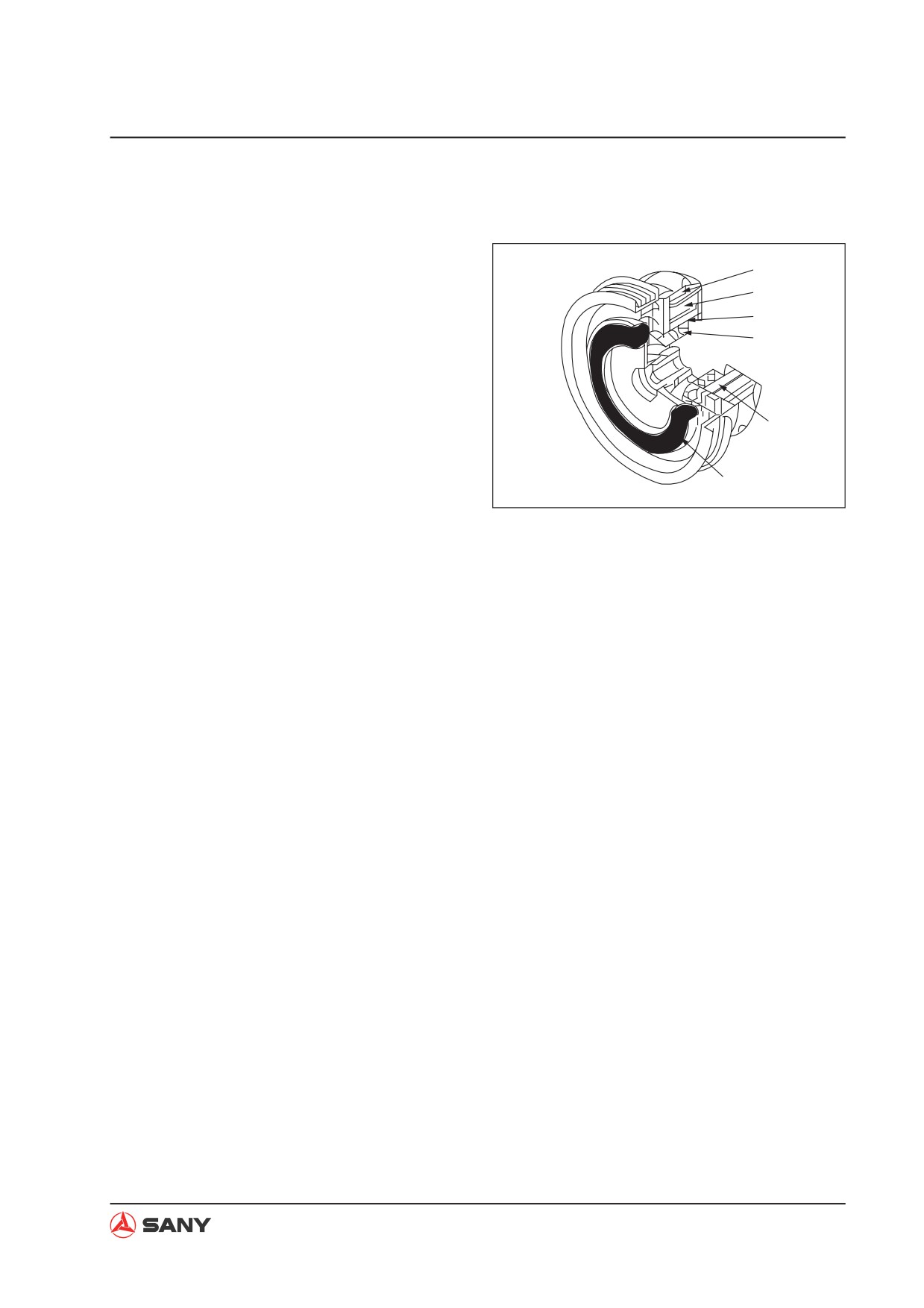
4.7.6 Clutch
1) Rotor
1
2) Stator coil
2
3) Snap ring
3
4) Ball bearing
4
5) Stator
6) Center piece
5
Ɣ
The electromagnetic clutch is used to
transmit moment of torsion. When the en-
6
ZX215-1002145
gine is operating, the compressor may not
be working. The clutch controls the opera-
tion of the compressor only when the air
conditioner is under refrigerating mode.
Ɣ
Operating principle
When the A/C switch is turned on, the
clutch coil with an electromagnet gener-
ates a magnetic field and attracts the metal
piece. The stator and rotor of the clutch are
engaged and drives the main shaft of the
compressor into rotation.
4-137
Structure and Function
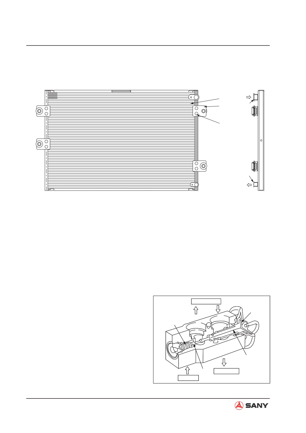
4.7.8 Condenser
1
4
2
3
5
ZX215-1002146
1) Condenser core
4)
Refrigerant inlet
2) Bracket
5)
Refrigerant outlet
3) Bolt with gasket
Function
Ɣ The condenser converts high-temperature,
high-pressure gas refrigerant (16Kg/cm²,
about 80°C) to high-temperature and high-
pressure liquid refrigerant (16Kg/cm², be-
low 60°C) through radiating.
4.7.7 Expansion valve
Evaporator
2
1) Spring
2) Diaphragm
1
3) Probe
4) Needle valve
Operating principle
3
Ɣ Refrigerant from the receiver tank spurts
4
Compressor
out via the orifice, turns into low-temper-
Reservoir
ature, low-pressure liquid (mist) after ex-
ZX215-1002147
panding, and enters the evaporator.
4-138
Structure and Function
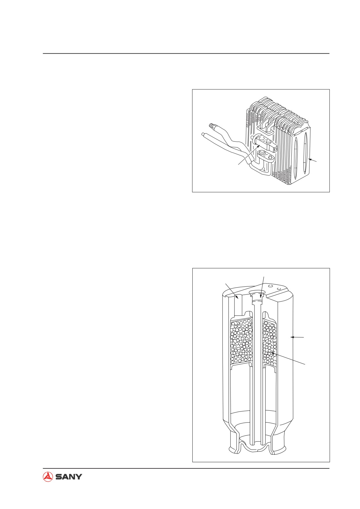
4.7.9 Evaporator
1) Expansion valve
2) Evaporator
Operating principle
Ɣ The evaporator is a kind of heat exchanger
that looks like a condenser. Hot air in the
cab is conducted into the evaporator via
the blower motor and undergoes heat ex-
2
change with the surface of the evaporator.
1
Heat is absorbed and hot air turns into
cold air, which flows into the cab through
the air ducts. Evaporator surface absorbs
ZX215-1002148
heatĺRefrigerant in the evaporator ab-
sorbs heat ĺ Refrigerant evaporates .
Evaporated refrigerant (gas) is absorbed
by the compressor.
4.7.10 Receiver tank
1) Inlet
2
1
2) Outlet
3) Receiver/dehydrator
4) Desiccant
Function
3
Ɣ Temporary storage of refrigerant
Ɣ Dehydration of refrigerant
4
Ɣ Dust removal from refrigerant
Ɣ Measure the volume of refrigerant
ZX215-1002149
4-139
Structure and Function
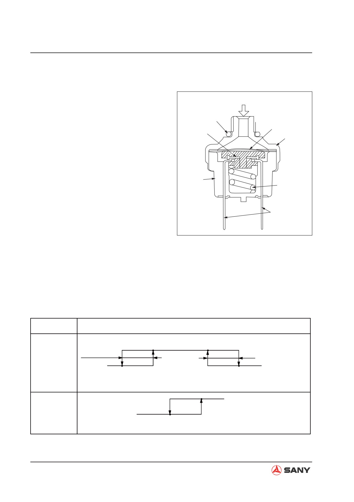
4.7.11 Pressure switch
1) O-ring
Pressure
2) Mobile contact point
3) Hood
1
4) Plug and fixed contact
7
2
5) Spring
6
6) Chamber
7) Diaphragm
Function
3
5
Ɣ The pressure switch is installed between
the receiver tank and the expansion
valve (hi-pressure pipe). It is a combina-
4
tion switch (Hi-Lo pressure combination
switch).
ZX215-1002150
Ɣ When pressure is excessively high, the
compressor stops.
Ɣ When pressure and temperature is very
low, the compressor stops.
Operating features
Feature
DIFF
DIFF
HI pressure
ON
operating value
Above 0.02 MPa
0.59±0.2 MPa
OFF
LO pressure
2.94~3.19 MPa
0.196±0.02 MPa
0.196~0.250 MPa
operating value
ON
MID pressure
OFF
operating value
1.23±0.1 MPa
1.52±0.08 MPa
4-140
Structure and Function
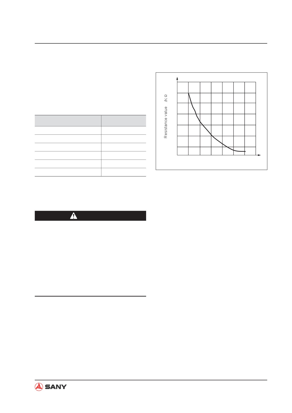
4.7.12 Fresh air sensor
The fresh air sensor is installed beside the
condenser or around the fresh air inlet. It mea-
sures the temperature of outside air and it is
12
composed of thermistors.
10
Technical specifications
8
Item
Specification
6
Service voltage range
4.4~5.6 V
4
Service temp range
-30~60 °C
Storage temp range
-40~90 °C
2
Resistance value
1700±85ȍ
-10
0
10
20
30
40
AT
B constant
3900±195 K
ZX215-1002151
Allowable operating current
1.6 mA (MAX)
4.7.13 Refrigerant
WARNING
Ɣ
Obey local material disposal regula-
tions. Never discharge refrigerant di-
rectly into the air.
Ɣ
Refrigerant R134 a is a harmless gas
under room temperature. It will change
into highly toxic gas when burning.
Ɣ
Refrigerant getting into eyes may cause
blindness. It may cause frostbite if
splashed on your skin.
1.
General property
Ɣ
High heat absorption and easy liquefaction
Ɣ
Non-flammable, nonexplosive
Ɣ
Stable chemical composition
Ɣ
Non-toxic
Ɣ
Non-corrosive
Ɣ
No hazard to clothing
4-141
Structure and Function
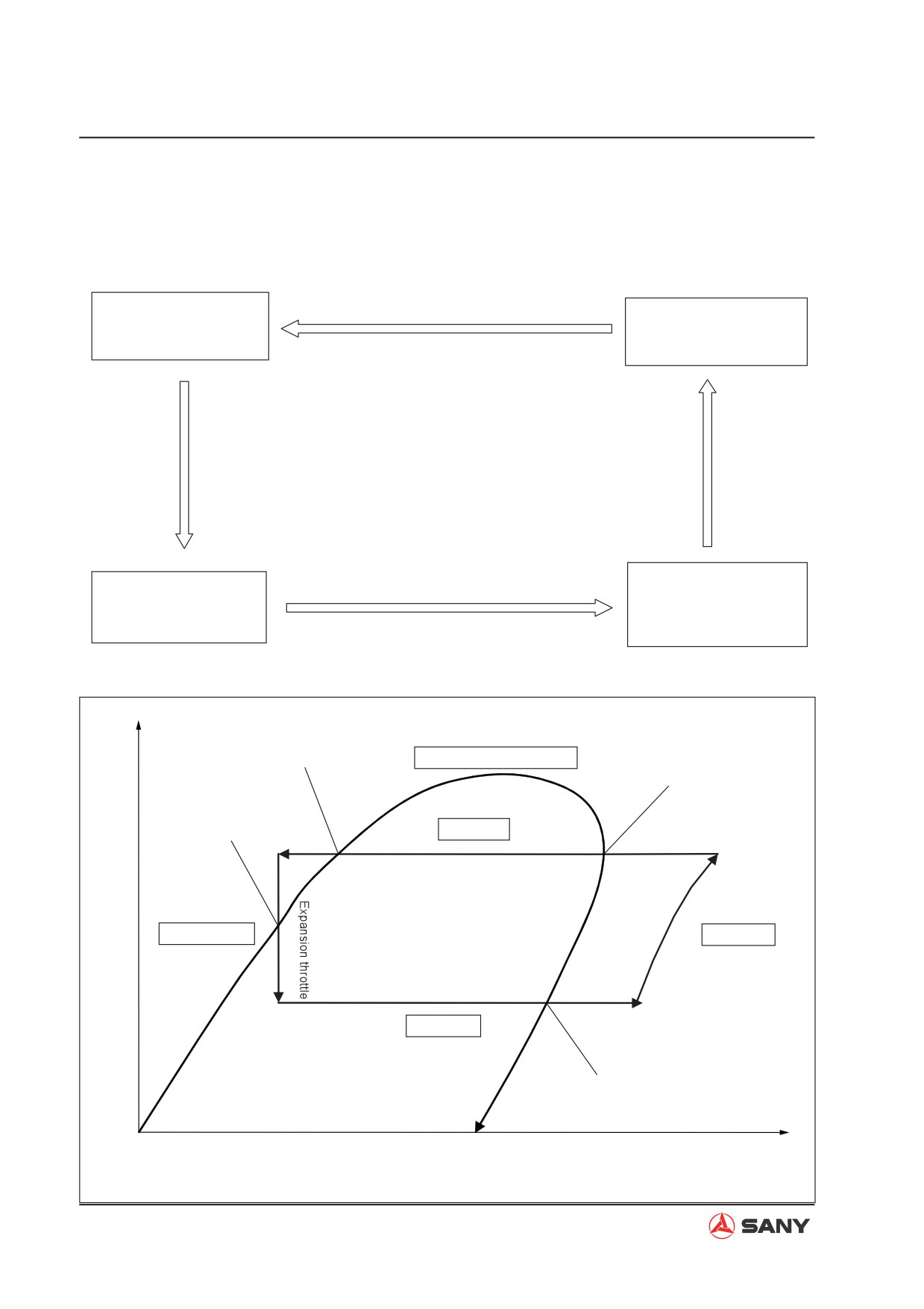
2. Refrigerant cycle
Ɣ After evaporation in the evaporator, refrigerant turns from gas into liquid via the compressor
and the condenser, which finishes a refrigerant cycle.
Compressor LO press. side (inlet): LO temp?LO press.?Gas
Pressure/Temperature: 2Kg/cm²đapprox. 8ć
Compressor
Evaporator
IntakeėDischarge
Absorb heatėEmit cold air
Compress HI press. side(outlet): HI temp\HI press.\Gas
Pressure/Temperature:16Kg/cm²ˈapprox. 80ć
Condensor (outlet): LO temp\LO press.\Mist
Pressure/Temperature: 2Kg/cm²ˈapprox. 0~2ć
Condensor (outlet)˖HI temp?HI pressure?Liquid
Expansion valve
Condensor
Pressure/Tempterature˖16Kg/cm²ˈBelow 60ć
Hi pressureėLo pressure
Via radiating: Gas refri-
Hi tempėLo temp
gerantėLiquid refrigerant
LiquidėMist
Ɣ Refrigerant cycle principle (pressure - enthalpy diagram)
lgp
Liquefaction completed
Refrigerant cyclic curve
Liquefaction starts
Throttling point
Condensor
Condensing process
Liquid
Compressing
Expansion valve
process
Compressor
Evaporating process
Evaporator
Gas-liquid mixture
Gasification completed
h=u+Apv(kJ/kg)
U Internal energy p Pressure V Special volume A Joule equivalent
4-142
Structure and Function
3. Feeding of refrigerant
Ɣ Filling method and volume:
1) Refrigerant: HFC-134a
2) Feeding volume: 850±50 g (for reference)
3) Feeding method: Feeding of liquid refrig-
erant from the low-pressure end is not al-
lowed. If feeding operation fails, discharge
the refrigerant that has been fed before re-
feeding.
ZX215-1002153
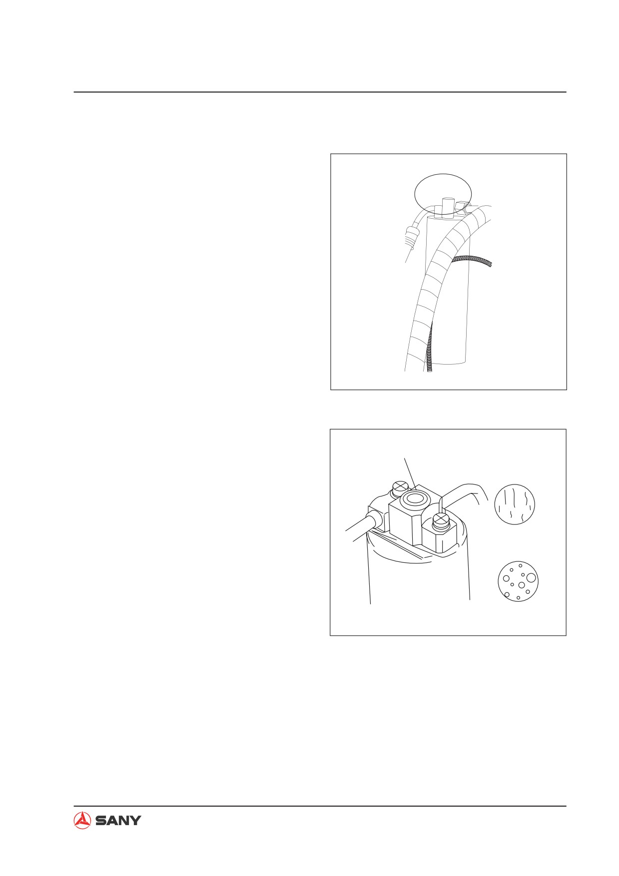
Ɣ Inspect the state of the refrigerant in the
A/C circulation system through the sight
Sight glass
glass:
1) Correct feeding: Foam is hardly observed
when the refrigerant is flowing. When en-
gine speed increases from idling to 1500
rpm, foam disappears and the refrigerant
Proper filling
turns clear.
2) Over-feeding: No foam can be observed
when refrigerant is flowing.
3) Under-feeding: Foam is always observed
Inadequate filling
when refrigerant is flowing.
ZX215-1002154
4-143
Structure and Function
4. Evacuation
Ɣ No moisture shall exit in the air condition-
ing unit. Refrigerant (R134a) is soluble in
water. Very small amount of moisture in
the unit can cause the orifice of the expan-
sion valve to ice up, or cause the compres-
sor valve to rust. To avoid such problems,
moisture in the system shall be removed
before refrigerant is added. To minimize
the residual moisture in the system, mois-
ture in the system can evaporate through
evacuating.
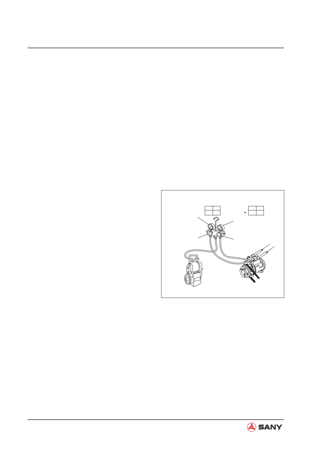
Evacuating steps
Step 1: Connect the manifold pressure gauge
1) Close the high-pressure valve (HI) and
Valve
low-pressure valve (LO) of the manifold
Lo-pres.gauge
LO
HI
LO
HI
above 750mmHg
Lo-pres.
ON
ON
OFF
OFF
pressure gauge.
gauge
Hi-pres. gauge
2) Connect the hoses (red, blue) to the auxil-
iary valve of the compressor.
Hi-pres. valve(ON)
Lo-pres. valve (ON)
Red hose - High pressure side (Mark D)
Green
Red
D
Blue hose - Low pressure side (Mark S)
Blue
S
NOTE: Connect the end of the hose with a
L to the auxiliary valve of the compressor.
Compressor
If connected inversely, the valve will not
Vacuum pump (running)
open. Besides, do not inversely connect
ZX215-1002155
the high-pressure end and the low-
pressure end.
3) Connect the green hose to the vacuum
pump.
4-144
Structure and Function
Step 2: Evacuation
1) Open the high-pressure valve (HI) and low-
pressure valve (LO) on the manifold pres-
sure gauge.
2) Turn on the vacuum pump and evacuate
for about 15 minutes.
3) When negative pressure reading on the
gauge (degree of vacuum) reaches above
750 mmHg, turn off the vacuum pump and
close the Hi-pressure valve and the Lo-
pressure valve on the gauge.
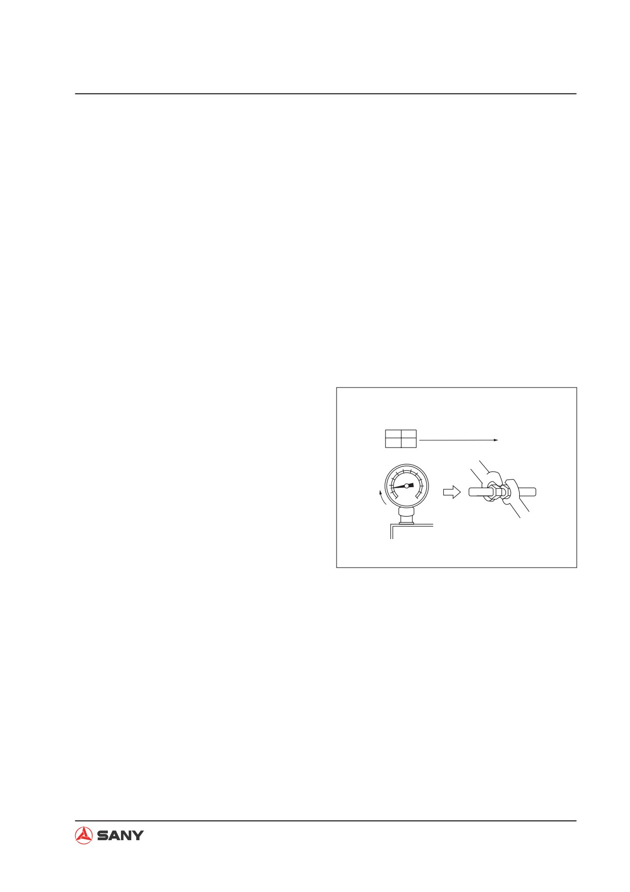
Step 3: Air - proof check
1) Keep the Hi- and Lo-pressure valve of the
manifold pressure gauge under closed
state for more than 5 minutes, and make
Valve
Lo
Hi
Wait 5 min. or more
Lo-press. gauge
sure the pointer on the gauge does not re-
OFF
OFF
returns to 0
turn to zero.
Lo-press. gauge
2) If the pointer returns to near zero, a leak-
age is available somewhere. Check and
adjust the pipe joint. Tighten the joint and
Pointer returns
conduct another evacuating operation until
to 0
Tighten pipe joint
no leakage is detected.
ZX215-1002156
4-145
Structure and Function
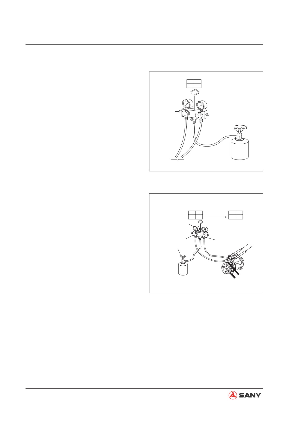
Step 4: Leak check
1) Connect the green hose that is previously
Valve
connected to the vacuum pump to the
Lo
Hi
OFF
OFF
fluorine cylinder.
2) Connect the other end of the green hose
to the pressure gauge. Open the valve of
Vent valve
the cylinder and press the vent valve of the
Release air
pressure gauge. (Do not press the valve
Open
with naked hand to avoid frostbite caused
by refrigerant). Release the air in the
hose with the pressure of the refrigerant.
Blue
(Release the vent valve when you hear a
Green
R134a
Red
squeezing sound).
To compressor
Fluorine cylinder
ZX215-1002157
3) Add refrigerant until pressure reading on
the Lo-pressure gauge is 1kgf/cm² . Hi-
Valve
pressure valve of the gauge is open at this
Lo-press gauge
Lo
Hi
Lo
Hi
at 1kgf/cm2
time. Close the Hi-pressure valve when
OFF
ON
OFF
OFF
Lo-pres. gauge
feeding is finished.
reads1kgf/cm2
4) Use a leak detector to check if leakage is
Lo-pres.valve (OFF)
Open Hi-pres.valve
available in the cooling system.
Cylinder valve (ON)
D
5) Make necessary repairs (tightening) if leak-
age is observed.
S
R134a
Compressor
Fluorine cylinder
ZX215-1002158
4-146
Structure and Function
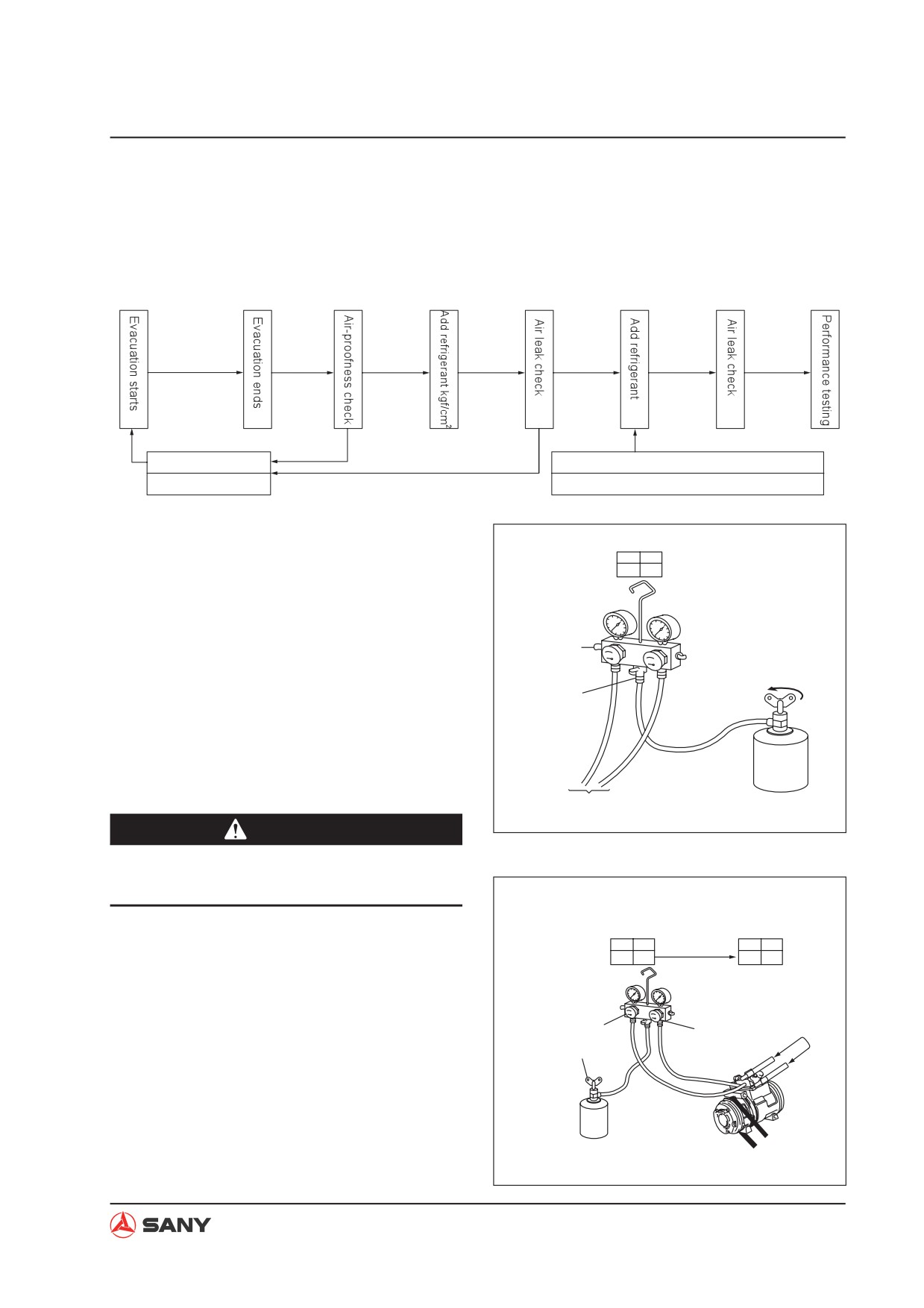
5. Refrigerant charging operation
Ɣ When evacuation is finished, add refrigerant into the cooling system as per the following in-
struction:
75cm-Hg or more
More than 15 min.
Wait 5 min.
Pres. gauge
normal
Pres. gauge
Tighten pipe joint
abnormal
(1) Compressor stopped, charge at hi-press end
Check leak point
(2)Compressor running, add at lo-press end
Charge at the hi-pressure side
Valve
Lo
Hi
1.
Remove the green hose of the manifold
OFF
OFF
pressure gauge from the vacuum pump
and connect it to the fluorine cylinder.
2.
Loosen the cylinder valve and press the
Vent valve
vent valve on the gauge. Use the pressure
Open
Loosen
of the refrigerant to release the air in the
this nut
hose.
Blue
NOTE: Release the vent valve when you
Green
R134a
hear a hissing sound.
Red
To compressor
Fluorine cylinder
ZX215-1002159
CAUTION
Ɣ
Do not press the valve with naked hand
to avoid frostbite.
3.
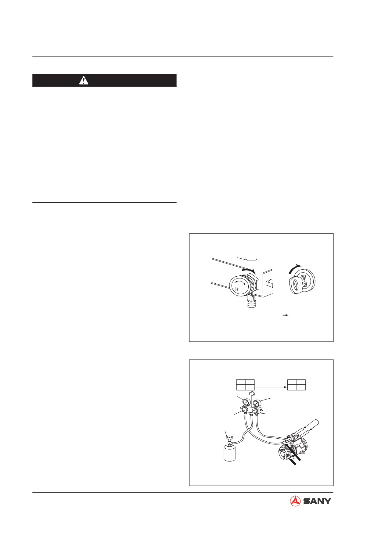
Open the hi-pressure valve of the manifold
Valve
Lo
Hi
A cylinder
Lo
Hi
pressure gauge and the cylinder valve with
(about 600g)
OFF
ON
OFF
OFF
the engine stopped. Fill about 600g of re-
frigerant.
gDo not operate compressor
Lo-press.
gDo not open Lo-pressure valve
valve (OFF)
4.
Close the hi-pressure valve of the pressure
Open Hi-press. valve
Fluorine cylinder
gauge and shut the cylinder valve.
valve (ON)
D
S
R134a
ZX215-1002160
4-147
Structure and Function
CAUTION
Ɣ Do not operate the compressor when
refrigerant charging is in progress.
Otherwise, refrigerant will counterflow
and cause the cylinder and hoses to ex-
plode.
Ɣ Operating the compressor with no re-
frigerant in the system will cause dam-
age to the compressor.
Ɣ Do not open the lo-pressure valve of the
manifold pressure gauge; otherwise,
the compressor will be damaged.
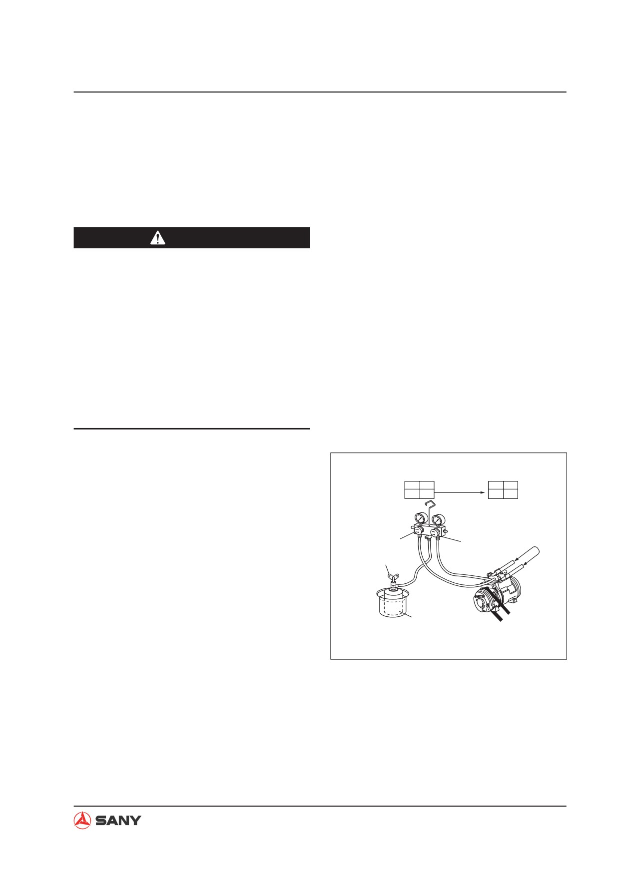
Charge at the lo-pressure side (refill)
1. Check that the hi-pressure valve of the
manifold pressure gauge is closed.
2. Start the engine.
Hi-press. valve (OFF)
ON
Manifold pressure
3. Turn on the A/C unit. Adjust Temperature
gauge
control switch to minimum.
I
4. Adjust engine speed to 1300 - 1500 rpm.
Start the engine
5. Open the Lo-pressure valve of the mani-
1300~1500rpm
fold pressure gauge and the cylinder valve.
Add refrigerant until no foam is observed
ZX215-1002161
through the sight glass.
Remark:
Valve
When no foam
Lo
Hi
Lo
Hi
is observed
Manifold pressure gauge reading (for refer-
ON
OFF
OFF
OFF
Lo-press. gauge
ence):
Hi-press. gauge
(1.5~2.5kgf/cm2)
(13~17kgf/cm2)
HIGH pressure:
Lo-press.
Hi-press. valve (OFF)
valve (ON)
(Never open it)
13~17kgf/cm² (when ambient temperature
Fluorine cylinder
is 30°C)
valve (ON)
LOW pressure:
1.5~2kgf/cm² (when ambient temperature
Compressor
Fluorine cylinder
running
is 30°C).
(never placed upside down)
ZX215-1002162
4-148
Structure and Function
6. When refrigerant charging is finished,
close the Lo-pressure valve of the mani-
fold pressure gauge and the valve of the
fluorine cylinder.
7. Check carefully for air leaks with a leak
detector.
CAUTION
Ɣ Opening the Hi-pressure valve of the
pressure gauge will cause pressurized
gas to counterflow and cause the hoses
and the fluorine cylinder to explode, re-
sulting in serious damage.
Ɣ When engine is running and charging in
progress, placing the fluorine cylinder
upside down will cause liquid refriger-
ant to be sucked directly into the com-
pressor and cause liquid compression,
resulting in equipment damage.
8. When ambient temperature is low
Valve
When refrigerant charging gets difficult
Lo
Hi
Lo
Hi
When no foam
ON
OFF
is seen
OFF
OFF
due to low temperature, put the cylinder in
warm water (max. 40°C).
9. When ambient temperature is high
Lo-pressure
Hi-pressure valve
valve (ON)
(OFF)
When ambient temperature is very high,
Cylinder valve
(ON)
cool the compressor with an electrical fan.
Compressor
Water less than 40°C
running
(Do not use hot water)
ZX215-1002163
4-149